

Introduction
This guide is about ultrafast optical pulse amplifiers — a photonics discipline quite distinct from RF, microwave, or radar pulsed amplifier design, and one with its own demanding physics and engineering constraints.
It is written for photonics researchers, optical engineers, and anyone encountering ultrafast amplifier systems for the first time, whether evaluating an architecture or trying to understand why these systems behave the way they do.
The guide builds progressively from foundational physics through chirped pulse amplification, amplifier architectures, seed lasers, and pumping, before arriving at the engineering challenges that make this field genuinely difficult to get right.
TL;DR
Ultrafast optical pulse amplification is a discipline where physics, engineering, and precision design are inseparable. Getting a system right depends on understanding why each design choice exists — from the stretcher-compressor pair in a CPA chain to the trade-offs between regenerative and multipass architectures — not just what each component does.
This article covers:

Physics of ultrashort pulse amplification vs. CW
Chirped pulse amplification: principles and purpose
Amplifier architectures: regenerative, multipass, fibre-based
Seed lasers and pumping mechanisms
ASE, gain narrowing, and nonlinear effects
Real-world ultrafast amplifier applications
What Are Pulsed Amplifiers?
A table-top laser system can generate peak powers that dwarf any continuous light source of comparable size — by many orders of magnitude. That counterintuitive fact sits at the heart of ultrafast optical pulse amplification, and it explains why this field demands an entirely different engineering mindset from any other branch of photonics.
The subject of this guide is ultrafast optical pulse amplifiers: devices designed to increase the energy and peak power of ultrashort light pulses in the picosecond (10⁻¹² s) to femtosecond (10⁻¹⁵ s) range. These are optical amplifiers — they act on light, not on electronic signals — and their purpose is to take low-energy seed pulses and boost them to energies and peak powers far beyond what the seed source alone can produce. This is a distinct domain from the RF and microwave pulsed amplifiers used in radar and electronic warfare; everything that follows concerns light.
Peak Power vs. Average Power
The conceptual pivot on which all of ultrafast amplification turns is the relationship between pulse duration, pulse energy, and peak power.
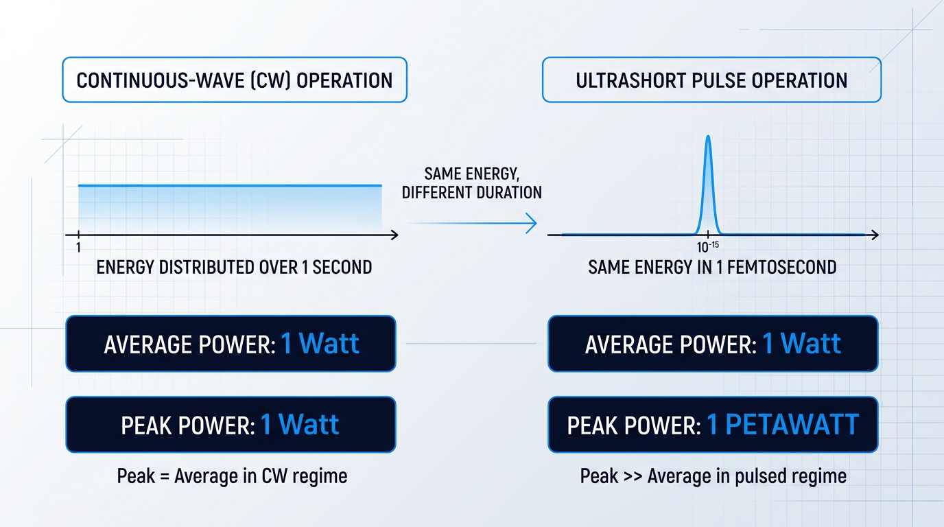
In continuous-wave (CW) operation, a laser delivers light as a steady, uninterrupted stream, and the power at any moment is essentially equal to the average power. Amplifying a CW beam means increasing that steady output level, and the engineer's primary concerns are gain, output power, noise figure, and thermal management.
Ultrashort pulses work on an entirely different principle: the same amount of energy is concentrated into an extraordinarily brief time window. Because peak power scales as pulse energy divided by pulse duration, compressing energy into a femtosecond-scale burst produces instantaneous intensities that dwarf the average power by many orders of magnitude.
This is precisely what makes ultrashort pulses so valuable scientifically and industrially: they interact with matter at intensities unreachable by any continuous source, enabling phenomena from precision micromachining to high-field physics. It is also what makes amplifying them so technically demanding.
The Time-Bandwidth Product: A Law, Not a Choice
Ultrashort pulses carry a second, less obvious consequence that shapes every aspect of amplifier design: the time-bandwidth product.
The Fourier relationship between time and frequency is a fundamental law of physics: the shorter a pulse's duration, the broader its spectrum of optical frequencies must be. This is not a design choice that can be engineered away — it is an inviolable physical constraint.
For a transform-limited pulse, the product of pulse duration and spectral bandwidth cannot fall below a minimum value set by the pulse shape. Shortening the pulse always broadens the spectrum — the amplifier must accommodate both simultaneously.
For amplifier designers, this constraint is critical: an ultrashort pulse occupies a broad range of optical frequencies, and the gain bandwidth of the amplifier's gain medium must be wide enough to support the entire pulse spectrum.
If the gain medium's bandwidth is narrower than the pulse's spectrum, it selectively amplifies the central frequencies while suppressing the spectral edges — a phenomenon called gain narrowing — which stretches the pulse in time and degrades its peak power. Bandwidth will reappear as a recurring design constraint throughout this guide.
Why Ultrafast Amplification Is a Different Problem
CW amplification is a well-understood engineering challenge. Ultrafast pulse amplification inherits all of those challenges and adds a qualitatively different set that simply does not exist in the CW regime.
Because the pulse spectrum is broad, different frequency components travel through the gain medium at slightly different speeds — chromatic dispersion. In a CW amplifier this effect is irrelevant; in an ultrafast amplifier it stretches the pulse temporally and must be carefully managed.
At the extreme peak intensities present inside an ultrafast amplifier, the gain medium and optical components respond nonlinearly: the refractive index becomes intensity-dependent, and the pulse accumulates phase distortion across its temporal profile.
When peak intensities approach the damage threshold of optical coatings, crystals, or fibre cores, optical damage becomes a hard physical limit — a ceiling on how hard the system can be driven before the hardware itself fails.
The Core Tension: Gain vs. Pulse Integrity
Ultrafast amplifiers must achieve very high gain: seed pulses from oscillators carry modest energies, while target outputs for research and industrial applications may require levels many orders of magnitude higher.
But as gain increases, so does the peak intensity inside the amplifier. At some point that intensity crosses thresholds where it either damages the gain medium outright or causes the pulse to accumulate nonlinear phase distortion severe enough to ruin its temporal and spectral profile.
This is the central engineering tension that runs through the entire field: the application demands very high gain, but the physics of ultrashort pulses means that high gain drives the system toward conditions that destroy either the hardware or the pulse itself. The architectures and techniques explored throughout this guide exist largely to navigate that tension.
Two Operating Regimes
Ultrafast amplifier systems are not a single monolithic category. They broadly divide into two operating regimes, each optimised for a different balance between pulse energy and repetition rate.
- High repetition rate: Megahertz to hundreds of kilohertz; moderate pulse energies but high average power. Typical in fibre-based systems for industrial processing, sensing, and LiDAR.
- Low repetition rate: Kilohertz or below; very high pulse energies and enormous peak powers. Typical in solid-state bulk amplifiers for scientific research, high-field physics, and fusion.
The right architecture depends entirely on whether the application needs high average power delivered rapidly or extreme peak power delivered at lower cadence — a distinction that drives fundamentally different design choices in gain medium selection, pumping geometry, and pulse management.
With that conceptual framework established — what ultrashort pulses are, why peak power is the dominant figure of merit, how the time-bandwidth product constrains amplifier design, and why the gain-versus-intensity tension is so fundamental — the next section moves into the underlying physics that governs how these systems actually behave.
Gain, Bandwidth, and Dispersion: The Physics
Amplifying an ultrashort pulse is not simply a matter of passing it through a gain medium and collecting more photons at the other end. The same physical properties that make femtosecond pulses so powerful — their extreme brevity, their broad optical spectrum, the colossal peak intensities they carry — also conspire to destroy them during amplification. Understanding precisely how requires working through four interconnected physical effects: gain bandwidth limitations, chromatic dispersion, nonlinear phase accumulation, and self-focusing.
Gain and Stimulated Emission
Amplification begins with stimulated emission: a signal photon enters a population-inverted gain medium, and each interaction with an excited atom or ion releases an identical photon — same frequency, phase, and direction — exponentially multiplying the signal.
In ultrafast pulsed amplifiers, the gain required is extraordinary: seed pulses from a mode-locked oscillator carry very low pulse energies, and a practical system may need to deliver output pulses many orders of magnitude more energetic, demanding very high accumulated gain across single or multiple amplification stages.
That gain translates directly into extreme intracavity intensity — and high gain does not come without a cost: any spontaneous emission present in the gain medium is amplified alongside the signal, a phenomenon that becomes a serious engineering concern at these gain levels, though its detailed treatment belongs later in this guide.
Gain Bandwidth and Gain Narrowing
A gain medium does not amplify all frequencies equally. It amplifies only within its gain bandwidth — the spectral window defined by the emission cross-section of the lasing transition — and the gain is highest near the centre of that window, falling away toward the edges.
This matters profoundly for ultrashort pulses. As the time-bandwidth product requires, a sub-100 fs pulse occupies a very broad optical spectrum — spanning several terahertz — and the gain medium must support that entire bandwidth to preserve the pulse duration through amplification.
When a pulse makes multiple passes through the gain medium — as it must to accumulate the very high gain these systems require — a process called gain narrowing sets in.
Each pass preferentially amplifies the spectral components closest to the gain peak, while the wings of the pulse spectrum receive comparatively less amplification and are progressively suppressed. The cumulative effect is a steady compression of the pulse's optical bandwidth, and by the time-bandwidth product, a narrower spectrum means a longer pulse: in high-gain systems, gain narrowing is one of the dominant limits on output pulse duration.
Chromatic Dispersion
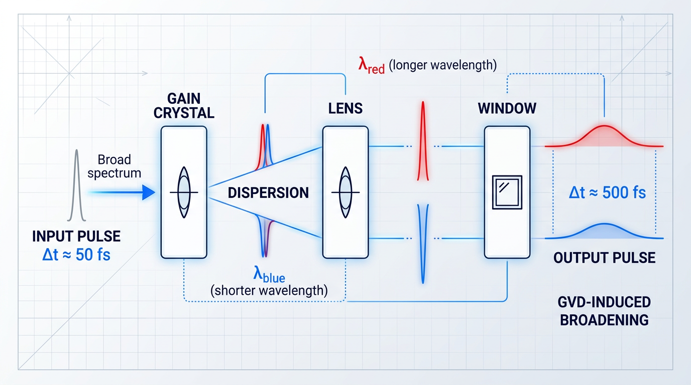
The second problem is group velocity dispersion (GVD). In any dispersive optical medium — a gain crystal, a lens, a window, even a mirror substrate — different frequency components of a broadband pulse travel at slightly different speeds.
The practical consequence is temporal pulse broadening: the red and blue spectral components of the pulse separate in time as they propagate, stretching the pulse from its original femtosecond duration into something considerably longer.
In the femtosecond regime, even a small thickness of glass introduces group delay dispersion large enough to measurably broaden the pulse — and across a full amplifier chain, the accumulated dispersion from every gain crystal, Pockels cell, lens, and window can stretch a femtosecond pulse to picosecond or even nanosecond durations.
Dispersion is cumulative and unavoidable: every optical element in the beam path contributes, and the total accumulated group delay dispersion across a multi-stage amplifier chain is not a small perturbation but a fundamental transformation of the pulse's temporal structure.
Nonlinear Effects and the B-Integral
At the peak intensities generated inside ultrafast pulsed amplifiers, a third class of effects emerges from the optical Kerr effect: the refractive index of any material in the beam path acquires an intensity-dependent component, so the effective index rises with increasing local intensity.
The direct consequence is self-phase modulation (SPM): as the pulse propagates, its own intensity profile modulates the local refractive index in time, imprinting a time-varying phase shift onto itself. This generates new spectral components and distorts the pulse's spectral and temporal shape.
Engineers track the accumulated nonlinear phase shift across an entire amplifier system using a single dimensionless quantity: the B-integral, defined as the integral of the nonlinear refractive index multiplied by the local intensity along the propagation path. It is the standard design metric for knowing how much nonlinear phase a pulse has accumulated by the time it exits the amplifier.
The B-integral is the number amplifier engineers calculate for every optical element in the chain. When it remains small (well below 1 radian), nonlinear distortion is negligible. As it approaches and exceeds a few radians, the risk of significant spectral distortion and self-focusing damage becomes serious — and the amplifier design must change.
The B-integral is not merely an academic metric: it is the practical number that determines whether an amplifier design is safe to operate, informing decisions about beam size, gain medium length, and the number of amplification passes at every stage of the system.
Self-Focusing and Optical Damage
The intensity-dependent refractive index does not only act in time — it also acts across the spatial profile of the beam. Because a real laser beam is more intense at its centre than at its edges, the Kerr effect creates a radially varying refractive index that acts as a converging lens: this is self-focusing.
As the beam focuses, its intensity rises further, which strengthens the Kerr lens, which focuses the beam more tightly — a runaway process that can collapse the beam into a narrow filament and catastrophically damage the gain medium or any downstream optical element.
Self-focusing is the hard physical ceiling that historically made it impossible to amplify ultrashort pulses to high energies by simply increasing pump power or adding gain stages: more gain means higher intensity, which means stronger self-focusing, which means damage — a fundamental barrier, not an engineering inconvenience.
Why the Femtosecond Regime Is Qualitatively Different
In the nanosecond pulse regime, peak intensities for a given pulse energy are far lower than in the femtosecond regime. Dispersion causes negligible broadening over typical propagation distances, and the Kerr nonlinearity remains far below any damaging threshold; amplifier design is dominated by gain, energy storage, and thermal management.
Compress that same pulse energy into femtoseconds rather than nanoseconds, and the peak intensity rises by many orders of magnitude. Dispersion now stretches the pulse significantly across just millimetres of glass, the B-integral accumulates rapidly, and self-focusing becomes a genuine threat within a single pass through the gain medium.
This is not a quantitative refinement of conventional amplifier design — it is a qualitative change in the dominant physics, where performance parameters such as pulse duration, pulse energy, peak power, and repetition rate are all shaped by the interplay of these effects rather than by gain alone.
Dispersion, gain narrowing, and the intensity-driven Kerr nonlinearity collectively defined the ceiling on achievable pulse energy for decades — until a single conceptual breakthrough changed the field entirely. That breakthrough, and how it turns these physical constraints into design tools rather than barriers, is what the next section covers.
Chirped Pulse Amplification: How CPA Works
For a long time, ultrafast laser science faced a hard ceiling: the more energy you tried to push into an ultrashort pulse, the more likely you were to destroy the very system doing the amplifying. The physics covered in the previous section made the problem vivid — peak intensities inside the gain medium would climb to levels that triggered catastrophic self-focusing, driving the B-integral beyond any safe limit and collapsing the beam before it could be extracted. High energy and ultrashort duration seemed fundamentally incompatible.
The breakthrough was conceptually simple, even if the engineering required to realise it is anything but. Chirped pulse amplification (CPA) resolves the impasse by decoupling the amplification step from the moment of peak intensity: stretch the pulse before it enters the gain medium, amplify it safely at low peak power, then recompress it afterwards.
The first stage is the pulse stretcher — typically a grating pair, or in fibre-based systems a long length of optical fibre — which introduces a controlled, frequency-dependent time delay known as a chirp. Different spectral components of the pulse arrive at different times, spreading it across a much longer duration (by factors of thousands or more, according to RP Photonics). Crucially, this stretching reduces the peak power dramatically without removing any energy from the pulse; the total energy is conserved.
The stretcher must introduce a precise, well-characterised chirp rather than random dispersion, because the compressor downstream must undo it exactly — any deviation propagates directly into the quality of the final output pulse.
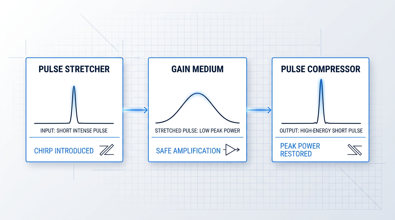
With the pulse now stretched, the amplification stage proceeds safely. The gain medium sees a long, low-intensity pulse and amplifies it without triggering the nonlinear distortions or optical damage that would have destroyed the system had the original ultrashort pulse been injected directly.
After amplification, a pulse compressor — a matched grating pair with opposite dispersion — removes the chirp and recompresses the pulse back to near its original, transform-limited duration. It is only at this final stage, after the pulse has left the gain medium entirely, that the peak power climbs to its full, extraordinary value.
Because the pulse is at its shortest — and therefore its most intense — at the final compressor grating, that grating is one of the most damage-vulnerable components in the entire system. LLE research confirms that compressor beam size is governed directly by the laser-induced damage threshold of the grating material: gold-coated gratings tolerate roughly 0.2–0.3 J/cm² and multilayer dielectric gratings 1–2 J/cm². This is why large beam diameters are required on the compressor gratings: spreading the energy over a greater area keeps the fluence safely below the damage threshold, even for petawatt-class systems where the grating apertures can approach one metre.
The stretcher and compressor must be matched with exceptional precision in their dispersive properties. The Martínez-type stretcher — which uses a telescope between two diffraction gratings to invert the angular dispersion and produce normal (positive) group delay dispersion — paired with a Treacy-type compressor providing anomalous dispersion, is the standard configuration for achieving this match. Any residual mismatch between the two leaves uncorrected chirp in the output, lengthening the pulse and degrading the peak power the system was designed to produce.
The gain medium never needs to see the full peak power of the final output pulse. By the time the pulse is recompressed to its full intensity, it has already left the amplifier entirely — peak power and pulse energy are decoupled during amplification.
CPA in practice: from table-top to petawatt
The practical consequences of CPA are extraordinary in scale. Table-top laboratory systems built around CPA routinely generate pulses with millijoule energies, femtosecond durations, and terawatt peak powers — the CUOS HERCULES laser at the University of Michigan, for example, achieves 300 TW in pulses shorter than 100 femtoseconds, all from a system that fits on a single optical table.
At the upper end of the scale, large national facilities push CPA to petawatt peak powers and beyond: the NSF ZEUS facility at CUOS operates a dual-beamline 3 PW system, and proposals for 10–100 PW sources are actively under development.
CPA was developed by Donna Strickland and Gérard Mourou in 1985 at the University of Rochester's Laboratory for Laser Energetics, with their foundational paper — "Compression of Amplified Chirped Optical Pulses" — published in Optics Communications that December. The technique's transformative impact on laser science was recognised with the 2018 Nobel Prize in Physics, awarded to Strickland and Mourou for their method of generating high-intensity, ultrashort optical pulses.
CPA does have its limits. In fibre-based systems, even aggressive pulse stretching cannot fully compensate for the high nonlinearity of the small fibre core: achievable pulse energies are practically limited to roughly 10 mJ, because stretching the pulse to more than a few nanoseconds is impractical, and the peak power at that duration is still constrained by catastrophic self-focusing in the fibre. Bulk solid-state CPA systems — using gain media such as Ti:sapphire or Yb-doped crystals — face no such confinement and can reach far higher pulse energies, making them the architecture of choice for the highest peak powers.
That distinction between fibre and bulk solid-state implementations shapes every major design decision in a high-energy ultrafast amplifier. The next section examines the principal amplifier architectures — regenerative, multipass, and fibre-based — and how each one puts CPA into practice.
Ultrafast Amplifier Architectures: Regenerative, Multipass, and Fibre-Based
Once CPA is in place, the next question is architectural: which amplifier design actually does the amplifying, and why does that choice matter? The answer depends on how much gain you need, what seed energy you are starting from, how many pulses per second the system must produce, and whether compactness or raw peak power is the governing constraint.
Regenerative Amplifiers
A regenerative amplifier traps the seed pulse inside an optical resonator that contains the gain medium, using a fast electro-optic switch — the Pockels cell — to inject it and later eject it.
Once inside, the pulse makes many round trips through the gain medium, accumulating gain on every pass; when the stored energy is sufficiently extracted, the Pockels cell switches again and the amplified pulse exits the cavity.
The resonator does two jobs simultaneously: it provides the repeated passes that build very high gain from a compact device, and it acts as a spatial filter, enforcing a clean mode profile with each transit — which is why regenerative amplifiers are known for excellent output beam quality.
Common gain media include Ti:sapphire and ytterbium-doped crystals, and systems typically operate at repetition rates around 1 kHz, though the exact rate is set by the pump laser and cavity design.
Because the pulse circulates through the gain medium many times, CPA is almost always used in conjunction: without stretching the pulse first, the peak intensities accumulating inside the resonator would damage optical components long before the desired gain level is reached.
The practical result is an architecture that can take a nanojoule-class seed and deliver millijoule pulse energies in a relatively compact footprint — making regenerative amplifiers the natural choice when very high gain is the primary requirement.
Multipass Amplifiers
A multipass amplifier takes a different approach: the pulse passes through the gain medium a fixed, predetermined number of times via a geometric mirror arrangement, with each pass spatially distinct from the last.
There is no resonator and no Pockels cell — the pulse simply follows a folded optical path through the gain medium and exits after completing the designed number of transits.
This simplicity is the architecture's main strength: fewer active components means fewer alignment-critical elements to maintain, and no resonator means no cavity stability to manage.
The trade-off is that the number of practical passes is limited by the geometry — the mirror arrangement becomes increasingly complex as pass count rises — and without resonator feedback, total gain is lower than a regenerative system for the same number of transits through the medium.
Multipass amplifiers are best suited to moderate gain from a higher-energy input: they are the right choice when the seed is already at a useful energy level and the goal is efficient energy extraction rather than very high gain from a weak seed.
Combining Architectures: The Amplifier Chain
In practice, the two solid-state architectures are frequently combined rather than used in isolation, because each covers the other's weakness.
A regenerative pre-amplifier does the heavy lifting from a nanojoule seed, building the pulse to the millijoule level where efficient energy extraction becomes possible; one or more multipass stages then boost the energy further without the overhead of a second resonator.
This regenerative-plus-multipass chain is the standard architecture for terawatt and petawatt-class systems, where the energy requirements exceed what a single stage can deliver and where each stage is optimised for the energy range it handles.
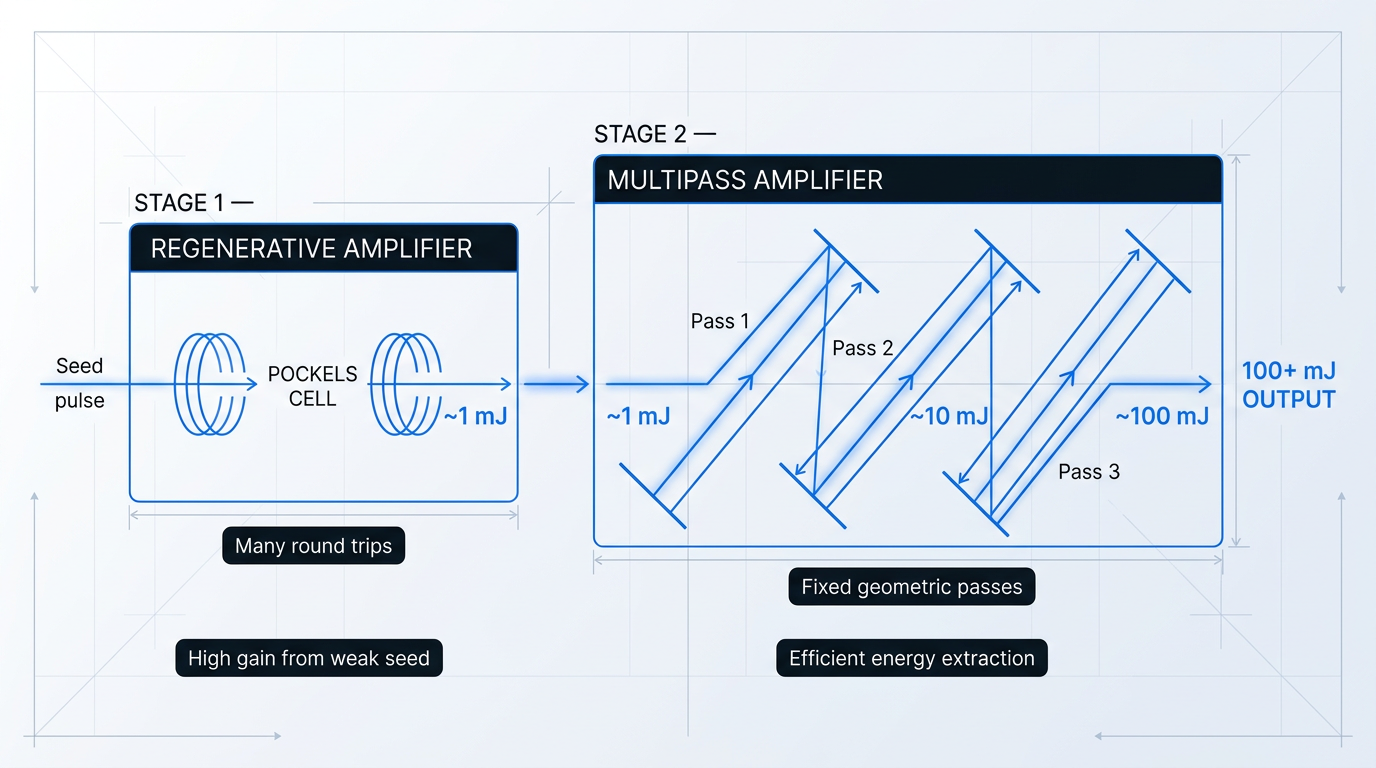
The table below maps the principal differences between regenerative and multipass designs across the dimensions that matter most when choosing between them.
| Dimension | Regenerative Amplifier | Multipass Amplifier |
|---|---|---|
| Gain mechanism | Many round trips in a resonator; resonator feedback accumulates gain efficiently | Fixed number of geometric passes; no resonator feedback |
| Typical gain | Very high; suitable for nanojoule-class seeds | Moderate; suited to millijoule-class or pre-amplified seeds |
| Seed energy requirement | Low — nanojoule inputs are typical | Higher — benefits from a pre-amplified input |
| Beam quality | Excellent; resonator acts as a spatial filter on every pass | Good; determined by gain medium and mirror alignment |
| Active switching | Pockels cell required for injection and ejection | None — purely geometric beam routing |
| Alignment complexity | Resonator cavity alignment; Pockels cell timing | Geometric mirror arrangement must be precisely set |
| Typical role in system | Primary amplifier stage; standalone or pre-amplifier in a chain | Final energy-boosting stage after a regenerative pre-amplifier |
Comparison of regenerative and multipass amplifier architectures across key engineering dimensions to help readers select the right design for their application.
The table makes the complementarity clear: regenerative designs excel where gain is the constraint; multipass designs excel where energy extraction efficiency is the constraint — which is exactly why combining them in sequence is the logical architecture for the highest-energy systems.
Fibre-Based Ultrafast Amplifiers
The third principal architecture family is built around rare-earth-doped optical fibre, with erbium-doped fibre amplifiers (EDFAs, operating in the 1530–1625 nm window) and ytterbium-doped fibre amplifiers (operating around 1030–1090 nm) as the two dominant variants.
The standard configuration is the MOPA (master oscillator power amplifier) architecture: a low-power seed source drives one or more fibre amplifier stages, with each stage adding gain until the target output power or pulse energy is reached.
Fibre amplifiers bring a distinct set of strengths that make them the preferred architecture for a wide class of applications.
- High gain efficiency: The waveguiding geometry confines pump and signal light together over long interaction lengths, producing high gain from modest pump powers.
- Broad gain bandwidth: Erbium and ytterbium gain bandwidths are wide enough to support amplification of pulses in the sub-picosecond regime.
- Excellent beam quality: Single-mode or near-single-mode fibre guides produce diffraction-limited output without the cavity alignment demands of bulk systems.
- High repetition rates: Fibre amplifiers are not limited by a Q-switched cavity; they can operate at megahertz repetition rates compatible with high-throughput applications.
- High average power: The distributed gain geometry dissipates heat efficiently, enabling high average output powers in a compact, robust physical format.
- Compact and robust: All-fibre or fibre-integrated designs are mechanically stable and well-suited to industrial and field-deployed environments.
The fundamental limitation of fibre-based CPA is geometric: the small effective mode area of the fibre core means that even at moderate pulse energies, the optical intensity inside the waveguide is high.
This drives the B-integral up rapidly, making self-phase modulation (SPM) and stimulated Raman scattering (SRS) the primary constraints on pulse energy — nonlinear effects that distort the pulse spectrum and ultimately limit how much energy can be extracted cleanly.
CPA is required in fibre systems even at relatively modest pulse energies precisely because of this intensity problem; and even with CPA, the practical pulse energy ceiling in fibre CPA systems is around 10 mJ.
Large mode area (LMA) fibres are the principal engineering response: by increasing the effective mode area of the core, LMA designs reduce the intensity for a given pulse energy, raising the nonlinear threshold and enabling higher pulse energies while preserving single-mode or near-single-mode beam quality.
The architecture map that follows from this is not a value judgement — it is a fit-for-purpose guide: fibre amplifiers lead where high repetition rate, high average power, compactness, and robustness are the governing requirements; bulk solid-state systems lead where the very shortest pulse durations (sub-20 fs) or the highest peak powers (terawatt to petawatt class) are required.
For engineers working in the erbium fibre space and needing to push the architecture to its practical limits, Woodrow Scientific's custom EDFA is a concrete example of what an end-to-end engineered platform looks like at the leading edge.
Built on a MOPA architecture across the full 1530–1625 nm window, the platform is configurable across pulse regime, pulse energy, and peak power — reaching pulse energies above 10 mJ and peak powers above 100 kW, which represents the leading commercially available performance for erbium fibre.
What distinguishes it from the fixed-catalogue erbium amplifiers that make up most of the market is the depth of engineering customisation: operating band, output power, pulse regime, cooling (air or water), form factor, delivery cable, and control firmware are all specified per project, up to the highest power levels commercially available.
Woodrow Scientific Limited (WSL) is a UK manufacturer founded in 2012 that designs, builds, qualifies, and supports its amplifiers entirely in-house on patented technology — not a reseller or importer — with engineering expertise rooted in Southampton's Optoelectronics Research Centre, the birthplace of the EDFA, and more than 200 years of combined engineering experience across the team.
That in-house capability matters in practice: many suppliers in this space are resellers with no ability to modify the product, diagnose a system-level problem, or accelerate a spare — WSL's direct engineering support throughout integration is a structural advantage, not a service add-on.
The platform is CE and UKCA certified, available in air- or water-cooled configurations, and can deliver both C-band and L-band output through a single cable — with operation at the eye-safe 1550 nm wavelength and reduced-hazard-zone builds available for applications where laser safety classification matters.
Even with CPA and large mode area fibres, fibre CPA systems are practically limited to around 10 mJ pulse energy. For applications demanding higher peak powers or shorter pulse durations, bulk solid-state architectures remain the only viable path — which is why the two architecture families are complementary, not competing.
Every amplifier architecture, whether fibre or bulk solid-state, ultimately depends on two things it does not generate itself: the seed pulse that enters it, and the pump energy that drives the gain medium — which is where the next section picks up.
Seed Lasers and Pumping Mechanisms in Ultrafast Amplifier Systems
An ultrafast amplifier chain is only as capable as the inputs that feed it: the seed laser that supplies the pulses, and the pump source that stores energy in the gain medium ready for extraction.
Seed lasers: the starting point of the amplifier chain
Ultrafast amplifiers do not generate pulses — they amplify pulses that originate in a separate source upstream. That source is a mode-locked oscillator, which produces a continuous train of ultrashort pulses at high repetition rates, typically between 50 MHz and a few gigahertz for solid-state lasers, with pulse energies in the nanojoule range.
The principal oscillator types used as seed sources each occupy a distinct region of parameter space: Ti:sapphire oscillators deliver some of the shortest achievable pulse durations, with few-cycle pulses below 10 fs possible via Kerr-lens mode locking; ytterbium-doped fibre and crystal oscillators (Yb:YAG, Yb:KGW, and related hosts) operate near 1030–1060 nm and are directly diode-pumpable; and erbium-doped fibre oscillators emit near 1550 nm, making them natural seeds for Er-doped fibre amplifier chains.
A critical design constraint governs the seed-to-amplifier interface: the optical bandwidth of the seed pulse must be supported by the gain bandwidth of the amplifier's gain medium.
Even within a well-matched gain bandwidth, the gain is not spectrally flat — frequencies near the gain peak are amplified more strongly than those at the spectral wings, progressively narrowing the amplified spectrum with each pass through the medium. This gain narrowing effect is worsened when the seed's bandwidth is poorly matched to the gain medium, compressing the amplified spectrum and lengthening the output pulse duration.
Because a mode-locked oscillator runs at repetition rates far above what a typical ultrafast amplifier can process — an 80 MHz oscillator feeding a 1 kHz Ti:sapphire regenerative amplifier, for instance — the vast majority of seed pulses must be discarded before injection.
A pulse picker, typically an acousto-optic modulator (AOM) or electro-optic modulator (EOM), performs this selection: it transmits one pulse in many thousands while blocking the rest, acting as the necessary interface between the high-repetition-rate oscillator and the lower-repetition-rate amplifier. The extinction ratio of the pulse picker matters beyond simple efficiency — any leakage of inter-pulse light raises the amplified spontaneous emission (ASE) background in the amplifier, a topic addressed in the engineering challenges section.
Pumping mechanisms: energising the gain medium
Creating population inversion in a solid-state gain medium requires a separate pump source — a laser or laser diode that transfers energy into the gain medium, exciting ions into the upper laser level from which stimulated emission can occur.
Ti:sapphire gain media require pumping in the blue-green spectral region, with frequency-doubled Nd:YAG or Nd:YLF lasers at 532 nm being the standard choice. These pump lasers are themselves pulsed or quasi-CW systems of considerable complexity — for many Ti:sapphire amplifier setups, the pump laser is as large, expensive, and technically demanding as the amplifier it drives.
Ytterbium-doped solid-state media (Yb:YAG, Yb:KGW, and related hosts) can be pumped directly by laser diodes, typically near 940 nm or at the zero-phonon line around 976 nm. This direct diode pumpability eliminates the secondary pump laser entirely, simplifying the system architecture substantially and contributing to the growing adoption of Yb-doped amplifiers in industrial and high-repetition-rate contexts.
Erbium-doped and ytterbium-doped fibre amplifiers are also pumped by laser diodes — most commonly at 980 nm for Er-doped fibre, and at 976 nm for Yb-doped fibre. Unlike solid-state systems, these pump diodes are compact, efficient, and integrate directly into the fibre architecture without any free-space beam-shaping optics.
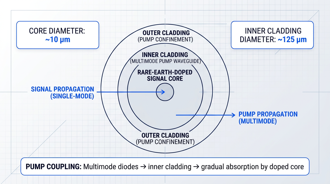
For high-power fibre amplifiers, a further architectural refinement is essential: pump light is launched not into the small rare-earth-doped signal core, but into the larger inner cladding of a double-clad fibre. This allows high-power multimode diodes — which cannot be efficiently coupled into a single-mode core — to deliver their pump power into the cladding waveguide, from which it is gradually absorbed by the doped core as it propagates along the fibre length.
The upper-state lifetime of the gain medium — the average time an excited ion remains in the upper laser level before spontaneously emitting — determines how much energy can be stored between pump and pulse, and imposes direct constraints on pump timing. Long-lifetime media such as Yb:YAG (with a fluorescence lifetime around 950 µs) can accumulate substantial stored energy and tolerate a wide range of pump-to-pulse timing; Ti:sapphire, with an upper-state lifetime of only approximately 3.2 µs, decays so rapidly that the pump pulse must be synchronised tightly to the amplifier cycle to avoid losing the stored energy to spontaneous emission before the seed pulse arrives.
Ti:sapphire's upper-state lifetime of ~3.2 µs means pump timing must be synchronised closely to the amplifier cycle — stored energy decays on a microsecond timescale. Yb:YAG, with a lifetime near 950 µs, imposes no such constraint, tolerating pump-to-pulse delays two orders of magnitude longer.
The seed laser and pump source together define the starting conditions for everything that follows: pulse bandwidth, stored energy, repetition rate, and the ASE environment the pulse must compete against. The next section examines what can go wrong as those conditions interact with the amplifier chain — covering gain narrowing, ASE accumulation, nonlinear effects, and optical damage management.
What Makes Ultrafast Amplifiers Hard to Build Well
Understanding how an ultrafast amplifier chain is assembled is the necessary first step. The harder question is why, even with every component correctly specified, these systems routinely push against physical limits that have no equivalent in continuous-wave or low-gain amplifiers.
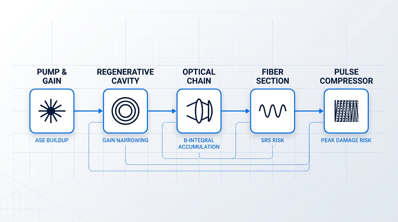
The four principal challenges — amplified spontaneous emission, gain narrowing, nonlinear phase accumulation, and optical damage — do not arise in isolation. They are coupled: the same high gain that makes ASE a concern also drives gain narrowing; the same peak intensity that threatens damage also accumulates nonlinear phase. Managing them requires tracking constraints across the full chain simultaneously, not optimising each element in turn.
Amplified Spontaneous Emission
Amplified spontaneous emission (ASE) arises because an excited gain medium does not wait for the signal pulse before emitting photons. Spontaneous emission occurs in all directions, and a fraction of it is guided back through the gain medium and amplified alongside the signal.
The consequences compound at high gain: ASE depletes the stored energy that would otherwise be available to the signal pulse, adds broadband noise to the output, and can saturate the gain medium before the signal pulse arrives, leaving little useful amplification for the intended pulse.
Regenerative amplifiers are particularly susceptible because gain accumulates over many round trips within a cavity, giving ASE repeated opportunities to build up alongside the signal over the same path.
The principal mitigation strategies address ASE at the architectural level rather than attempting to suppress it within a single gain stage:
- Inter-stage optical switches: Acousto-optic or electro-optic modulators placed between gain stages open only during the signal pulse window, preventing ASE from propagating through the full chain.
- Faraday isolators: Placed between stages to block backward-propagating ASE, which would otherwise be re-amplified in the preceding gain stage.
- Pump-signal timing control: Minimising the interval between pump pulse and signal pulse reduces the window during which ASE can accumulate in the excited gain medium.
The practical implication is that high-gain ultrafast amplifier systems are necessarily multi-stage designs with active switching between stages — a complexity cost that is unavoidable above high gain thresholds, not a discretionary design choice.
Gain Narrowing
Every gain medium amplifies frequencies near its gain peak more strongly than those at the spectral wings. Across many passes or stages — as encountered in regenerative amplifiers and multi-stage chains — the cumulative effect is a progressive compression of the pulse's optical bandwidth, a phenomenon known as gain narrowing.
Narrower bandwidth means a longer transform-limited pulse duration: gain narrowing is therefore a fundamental limit on how short the output pulse can be, and it becomes increasingly severe as total system gain rises.
Three mitigation approaches are well established in practice:
- Spectral pre-shaping: The seed pulse spectrum is shaped before amplification to pre-emphasise the wings, so that after gain narrowing the amplified spectrum is approximately flat.
- Broad gain bandwidth media: Ti:sapphire, with its exceptionally wide gain bandwidth, is far less susceptible to gain narrowing than narrower gain media at equivalent total gain.
- AOPDFs (Dazzlers): Acousto-optic programmable dispersive filters provide real-time dynamic control of spectral amplitude and phase, compensating gain narrowing pass by pass.
The connection to pulse duration limits established in the physics section is direct: gain narrowing is the mechanism by which the time-bandwidth product constraint becomes a practical engineering problem rather than an abstract one, and spectral management is therefore a core design discipline in any high-gain system.
Nonlinear Effects and the B-Integral
As established in the physics section, the B-integral tracks the accumulated nonlinear phase shift a pulse acquires as it propagates through optical elements in the amplifier chain. When this accumulated phase becomes significant, self-phase modulation (SPM) distorts the pulse spectrum and temporal profile in ways that degrade compressibility and spatial beam quality.
CPA's role here is precisely what the CPA section described: stretching the pulse before amplification reduces its peak intensity inside the gain medium, keeping the B-integral within acceptable bounds. Large mode area designs serve the same purpose by spreading the pulse energy over a larger cross-section, reducing intensity at a given pulse energy.
In fibre amplifiers, the small mode area that concentrates light for efficient guidance also concentrates intensity, making nonlinear effects significantly more acute than in bulk solid-state systems. Two fibre-specific processes are particularly relevant at high peak powers.
Stimulated Raman Scattering (SRS) transfers energy from the signal to a longer-wavelength Stokes component when sufficient Raman gain accumulates, degrading signal fidelity. It is mitigated by limiting fibre length and using large mode area fibres to reduce the intensity at which Raman gain builds.
Stimulated Brillouin Scattering (SBS) requires coherent phonon build-up that the broad optical bandwidth of femtosecond and picosecond pulses effectively suppresses. SBS becomes relevant when fibre amplifiers operate in the nanosecond regime or with spectrally narrow inputs — it is not a primary concern for ultrashort pulse systems specifically.
The infographic below maps where each major challenge arises along a representative amplifier chain, showing how nonlinear phase accumulates across optical elements and where fibre-specific nonlinearities become relevant.
Optical Damage and the Compressor
Efficient energy extraction from a gain medium requires the pulse fluence to approach the saturation fluence of that medium. Operating well below saturation fluence leaves stored energy unextracted; operating near or above it risks optical damage to coatings, surfaces, and the gain material itself.
The most damage-susceptible point in the entire chain is not the gain medium — it is the pulse compressor. After recompression, the pulse reaches its shortest duration and therefore its highest peak intensity at the final grating surface, making the compressor gratings the component most likely to be destroyed if fluence is not carefully managed.
The standard mitigation is to expand the beam to a large diameter before it reaches the compressor gratings, distributing the pulse energy over a larger area and reducing the fluence at the grating surface accordingly. In high-energy systems, this often requires grating apertures of tens of centimetres.
CPA's contribution is again central: by keeping the pulse stretched throughout the amplification chain, peak intensity — and therefore damage risk — is deferred until after the compressor, where it is the intended output rather than an unwanted hazard.
The ASE suppression architecture, gain narrowing compensation strategy, B-integral budget, and damage fluence margins must all be tracked across the full amplifier chain in concert. A system optimised element by element — without accounting for how each constraint interacts with the others — will fail at the chain level even if every individual component is correctly specified.
That whole-chain discipline — holding ASE, gain narrowing, nonlinear phase, and damage margins simultaneously within bounds across the full operating envelope — is what separates a well-engineered ultrafast amplifier from one that performs only at nominal conditions.
With the engineering challenges understood, the final question is where these carefully designed systems are actually deployed — and the breadth of applications, from high-field physics to precision material processing, reflects just how capable a well-engineered pulsed amplifier chain can be.
Applications of Ultrafast Optical Pulse Amplifiers
The physics and engineering covered throughout this guide do not exist in a vacuum — they translate into a remarkable range of real-world deployments, spanning from sub-femtosecond laboratory science to kilometre-scale remote sensing. Understanding why each of these domains demands ultrafast amplification specifically is the payoff for the technical groundwork laid in the preceding sections.
High-field physics and attosecond science
Terawatt and petawatt CPA systems have opened a regime of strong-field laser physics that was entirely inaccessible before chirped-pulse amplification existed — specifically, the generation of attosecond pulses via high harmonic generation (HHG), in which an intense femtosecond pulse focused into a gas jet drives electrons to emit extreme-ultraviolet harmonics whose spectral phase is locked, producing bursts of light shorter than one femtosecond.
Attosecond pulses are the only probe that operates on the natural timescale of electron dynamics — the motion of bound electrons in excited atoms and molecules evolves on timescales of tens to hundreds of attoseconds, and no other measurement technique reaches this resolution.
Facility-scale CPA systems represent the most extreme end of this application domain: the OMEGA EP petawatt-class laser at the University of Rochester's Laboratory for Laser Energetics delivers pulses as short as 1 ps with energies up to 2.6 kJ per beam, while the ELI Beamlines facility near Prague operates the L3 HAPLS system — designed to deliver petawatt-class pulses below 30 fs at a 10 Hz repetition rate — alongside the L4 ATON, designed for 10 PW peak power at 150 fs pulse duration.
Laser material processing and micromachining
When a femtosecond pulse strikes a material, its duration is shorter than the timescale on which thermal energy diffuses into the surrounding lattice — this is the physical basis of cold ablation, in which material is removed with a minimal heat-affected zone, leaving edges that are clean rather than scorched or cracked.
This contrasts sharply with nanosecond or CW laser processing, where thermal conduction during the pulse deposits heat well beyond the intended interaction volume, causing collateral damage that limits precision in metals, glass, ceramics, and biological tissue alike.
The most widely recognised medical application is femto-LASIK ophthalmic surgery: the Nobel Prize popular information notes that millions of eye operations are performed every year using the sharpest of CPA-derived laser beams, with femtosecond pulses enabling incisions in corneal tissue that nanosecond systems cannot replicate with the same precision.
Pump-probe spectroscopy
Femtosecond pulses act as the world's fastest stroboscope: in pump-probe spectroscopy, a strong pump pulse excites a molecular or electronic system, and a time-delayed probe pulse interrogates the resulting dynamics — with temporal resolution limited only by the pulse duration itself.
The time it takes for atoms in a molecule to perform one vibration is typically 10–100 fs, meaning that femtosecond pulses are precisely matched to the timescale of bond-breaking, charge transfer, and other fundamental chemical events — processes that appear instantaneous to any slower measurement technique.
This capability, pioneered by Ahmed Zewail and recognised with the 1999 Nobel Prize in Chemistry, opened the field of femtochemistry and continues to evolve toward attosecond pump-probe experiments capable of resolving electron dynamics inside atoms — a frontier that depends entirely on the amplified pulse energies that CPA systems provide.
Three further application domains are well served by pulsed amplifiers, each with distinct requirements that connect directly to the architectures and wavelength windows discussed earlier in this guide.
- LiDAR and remote sensing: Pulsed fibre amplifiers at 1550 nm — where light is absorbed by the cornea and lens before reaching the retina — allow higher transmitted power than 905 nm systems, extending range in autonomous vehicle, wind-sensing, and atmospheric measurement deployments.
- Free-space optical communications: High-power pulsed amplifiers in the 1530–1625 nm erbium-fibre window support ground-station uplinks for free-space optical (FSOC) links operating at 1550 nm, a wavelength also preferred for its compatibility with mature telecom infrastructure.
- Inertial confinement fusion research: Petawatt CPA systems — including OMEGA EP and ELI Beamlines — drive fast-ignition and implosion experiments, representing the most demanding engineering environment for ASE suppression, nonlinear control, and optical damage management.
Taken together, these domains span an extraordinary range of scale: from tabletop femtochemistry instruments resolving molecular vibrations to football-field-sized laser facilities pursuing nuclear fusion, and from precision surgical tools to kilometre-range atmospheric sensors.
The same CPA principle that enables sub-micron corneal incisions in ophthalmic surgery also underpins petawatt laser facilities exploring inertial confinement fusion — the engineering challenges differ by many orders of magnitude, but the underlying physics is identical.
Having traced ultrafast pulsed amplifiers from their physical foundations through their architectures, engineering constraints, and real-world deployments, the guide's final section draws these threads together — reflecting on what the field has achieved and where the most significant open questions remain.
Conclusion
Ultrafast optical pulse amplification: key takeaways
Ultrafast optical pulse amplification is a systems discipline: the seed, the stretcher, the gain stages, the compressor, the ASE budget, and the nonlinear phase accumulation all interact, and none can be optimised without accounting for the rest.
Having followed that arc, you now have a coherent framework for evaluating architectures and asking the right questions of any manufacturer or specialist resource.
For those working in the 1530–1625 nm erbium window, Woodrow Scientific's custom EDFA platform is worth consulting: a UK manufacturer that engineers, builds, and supports its amplifiers in-house, configured end-to-end to the application.
Frequently asked questions about pulsed amplifiers
Common questions about ultrafast optical pulse amplification, answered independently — each response stands on its own without requiring familiarity with the rest of this guide.
In the ultrafast optical context, a pulsed amplifier is a device that increases the energy and peak power of ultrashort light pulses — typically in the picosecond to femtosecond duration range — by passing them through a pumped gain medium such as Ti:sapphire or Yb-doped glass. The gain medium has been excited by a pump laser, and the signal pulse extracts that stored energy as it passes through. This is distinct from a continuous-wave (CW) optical amplifier, which amplifies a steady, uninterrupted beam rather than discrete pulses. It is also entirely separate from RF or microwave pulsed amplifiers used in radar, electronic warfare, and EMC testing — those operate on electrical signals at radio frequencies, not on light. Readers arriving from that domain are in a different field; this page addresses optical pulse amplification only.
Chirped pulse amplification (CPA) works by stretching an ultrashort pulse in time before amplification, amplifying the now-lower-intensity stretched pulse through the gain medium, and then recompressing it back to near its original duration. Substantial stretching factors are used — often orders of magnitude — reducing the pulse's peak power by a corresponding amount during the amplification stage. Without CPA, the peak intensities reached inside the gain medium during high-energy amplification would exceed the optical damage threshold of the components, or trigger severe nonlinear distortions — including self-focusing and self-phase modulation — that would degrade or destroy the pulse. CPA makes high-energy ultrafast amplification physically possible by keeping the instantaneous intensity within safe limits throughout the amplification process.
A regenerative amplifier traps the seed pulse inside an optical resonator using a fast electro-optic switch — typically a Pockels cell — which injects the pulse, holds it for many round trips through the gain medium, then ejects it once sufficient energy has been extracted. This architecture delivers very high gain from a low-energy seed, making it well suited to amplifying nanojoule pulses up to the millijoule level. A multipass amplifier takes a different approach: a fixed geometric arrangement of mirrors directs the beam through the gain medium a set number of times without any resonator or fast switching element. This makes the design simpler and more stable, but the number of practical passes is limited, so achievable gain per stage is lower. In practice the two architectures are often complementary: a regenerative pre-amplifier provides the bulk of the gain from a weak seed, and a multipass stage then boosts the pulse to its final energy.
The fundamental constraint is the small effective mode area of the fibre core. Confining light to a core only a few micrometres across concentrates optical energy into a tiny cross-section, producing high intensities even at moderate pulse energies. As peak intensity rises, nonlinear optical effects set in — principally self-phase modulation and stimulated Raman scattering — which distort the pulse spectrally and temporally. At higher intensities still, catastrophic self-focusing driven by the Kerr effect can physically damage the fibre. Chirped pulse amplification and large mode area fibres both mitigate these effects, but each has practical limits. Even with both measures combined, fibre-based ultrafast amplifiers reach an energy ceiling well below what bulk solid-state architectures can achieve. For the very highest pulse energies and peak powers, bulk solid-state designs — where the beam can be expanded freely to manage intensity — remain the necessary choice.
Gain narrowing is an effect in which repeated amplification progressively reduces the optical bandwidth of a pulse, ultimately limiting how short the output pulse can be. A gain medium does not amplify all optical frequencies equally: those near the centre of the gain peak are amplified more strongly than those in the spectral wings. With each additional pass through the gain medium, the wings receive proportionally less amplification and the pulse's spectrum contracts towards the gain peak. Optical bandwidth matters because pulse duration and bandwidth are linked by the time-bandwidth product — a fundamental Fourier relationship stating that a narrower spectrum corresponds to a longer minimum achievable pulse duration. In high-gain systems, gain narrowing can substantially lengthen the output pulse relative to the seed, setting a floor on achievable pulse duration regardless of how broad the seed's initial spectrum was.
In any pumped gain medium, excited atoms or ions spontaneously emit photons in random directions. Some of those photons happen to travel along the gain medium and are amplified just like the intended signal — this is amplified spontaneous emission (ASE). In high-gain systems, ASE can become significant enough to deplete the stored energy in the gain medium before the signal pulse arrives, add broadband noise to the output, and in extreme cases saturate the amplifier entirely. For this reason, single-stage gain is kept within bounds, and multi-stage amplifier designs with optical switches — acousto-optic or electro-optic modulators — placed between stages are the standard approach to suppression. These switches open only during the signal pulse window, blocking ASE from building up between stages. Faraday isolators between stages additionally suppress backward-propagating ASE, preventing it from re-entering earlier amplification stages.