


Introduction
Stimulated Brillouin scattering sits at the boundary between optics and acoustics — a place where intense light and the mechanical properties of a medium become inseparable.
This guide is written for engineers, researchers, and advanced students who need to understand SBS at a depth that genuinely shapes how they design, build, and troubleshoot optical systems.
It moves from the underlying physical mechanism and mathematical framework through to fibre-specific behaviour, engineering mitigation, and applications — covering the full arc from first principles to practical consequence.
Throughout, every equation is treated as a tool for building intuition rather than an end in itself — the formalism always serves the physical picture.
TL;DR
SBS is both a fundamental power limit and a precision instrument — the same physics that caps what you can transmit through a fibre also enables kilometre-scale distributed sensing and ultra-narrow-linewidth lasers.
Understanding it deeply, not just avoiding it, is what separates robust system design from repeated surprises.
This article covers:

Electrostriction, acoustic phonons, and the feedback loop
Phase matching and the Brillouin frequency shift
The SBS gain spectrum and threshold conditions
SBS in fibres: confinement, effective length, susceptibility
Suppression strategies and engineering trade-offs
Distributed sensing, photonic integration, and Brillouin lasers
What is stimulated Brillouin scattering?
When a sufficiently intense beam of light travels through a medium, it does not simply pass through — it begins to reshape the medium itself, and that reshaping reflects the light back. This is the essence of stimulated Brillouin scattering: a third-order nonlinear optical process in which intense light coherently couples to acoustic phonons in a material, generating amplified backscattered light that is shifted downward in frequency.
The phenomenon takes its name from the French physicist Léon Brillouin, who predicted the scattering of light by thermally excited acoustic waves in 1922. It belongs to the family of inelastic scattering processes, in which the scattered photon carries a different energy from the incident photon. Raman scattering is its closest relative in this family, but the two are distinct: Raman involves optical phonons at terahertz frequencies, whereas Brillouin involves acoustic phonons at gigahertz frequencies — a difference that has profound consequences for how each process behaves in optical fibres.
From spontaneous to stimulated: a critical distinction
At any finite temperature, a material contains thermally generated acoustic waves — random density fluctuations that scatter a small fraction of any incident light. This is spontaneous Brillouin scattering: a passive, always-present background process that requires no particular optical power and produces only a weak, frequency-shifted return signal.
What changes at high optical power is qualitative, not merely quantitative. Rather than passively scattering off pre-existing thermal fluctuations, the intense light field begins to drive the acoustic wave itself through a process called electrostriction — the tendency of a dielectric medium to compress in regions of high optical intensity.
This driving creates a positive feedback loop: the acoustic wave scatters some of the pump light into a backscattered Stokes wave, and the interference between the pump and that Stokes wave reinforces the acoustic wave further, which in turn amplifies the Stokes wave, and so on. The result is an exponential buildup of both the acoustic wave and the backscattered signal — coherent, self-reinforcing, and categorically different from the spontaneous case.
Three participants are central to every SBS interaction, and their names recur throughout this guide:
- Pump wave: The incident high-power light that drives the interaction. It supplies the energy and initiates the acoustic grating through electrostriction.
- Stokes wave: The backscattered light, downshifted in frequency relative to the pump. It grows exponentially once the feedback loop is established.
- Acoustic phonon: The mediating sound wave that couples pump and Stokes. It carries the energy difference between the two optical waves.
The most intuitive way to understand the frequency relationship between these three participants is through the Doppler picture. The acoustic grating — a periodic density modulation moving through the medium at the acoustic velocity — acts as a mirror travelling away from the incoming pump light. Reflection off a receding mirror produces a Doppler downshift, so the backscattered Stokes wave emerges at a lower frequency than the pump, offset by exactly the acoustic phonon frequency. This offset is the Brillouin frequency shift, a quantity determined by the acoustic velocity and the refractive index of the medium; its precise value will be derived in the phase-matching section later in this guide.
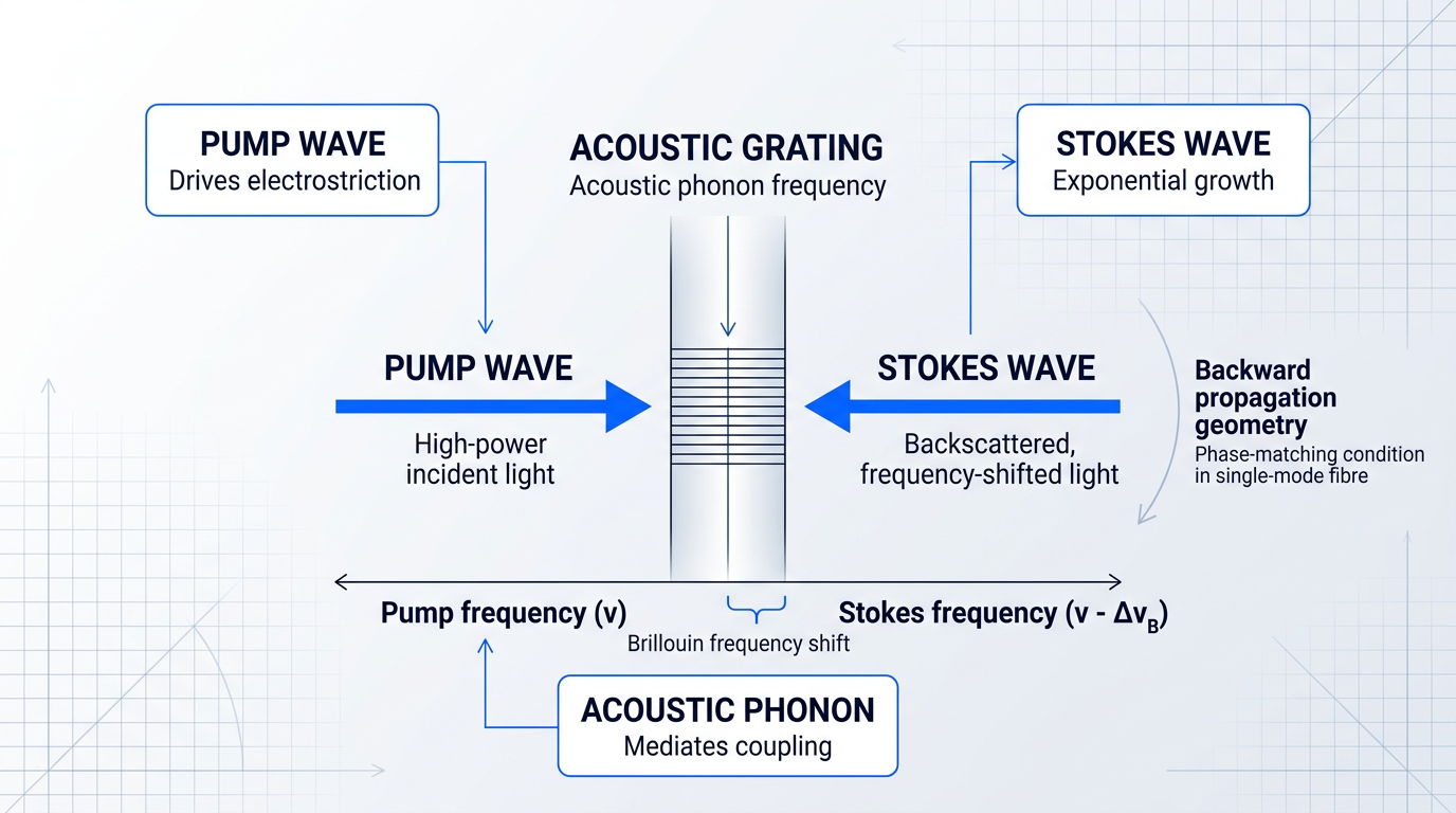
In optical fibres, backward propagation is the overwhelmingly natural geometry for SBS: the Stokes wave travels in the direction opposite to the pump. This is not incidental — the phase-matching conditions in a single-mode fibre are satisfied for counterpropagating pump and Stokes waves, not co-propagating ones. The acoustic grating couples the two optical waves most efficiently when they travel in opposite directions, which is why backward SBS dominates fibre systems in practice.
Above the SBS threshold power, the process can reflect the majority of incident optical power back toward the source. For narrow-linewidth CW systems in optical fibres, this is not a minor perturbation — it is a fundamental power limit that shapes system architecture from the ground up.
The practical consequence is stark: once optical power exceeds the SBS threshold, the fibre effectively becomes a mirror, redirecting most of the launched power back toward the source rather than delivering it to the load. Quantifying that threshold — and understanding what controls it — is the subject of later sections in this guide.
That conceptual picture sets the stage for a deeper question: precisely how does electrostriction drive the acoustic wave, and what sustains the feedback loop with such efficiency? The physical mechanism behind those dynamics is examined in the next section.
Electrostriction, Phonons, and the Feedback Loop
The previous section established that an intense pump field drives an acoustic wave and that a Stokes wave grows from the interaction — but it left open a precise question: what physical force actually compresses the glass? The answer is electrostriction, and understanding it is the key to understanding why stimulated Brillouin scattering behaves the way it does.
Electrostriction is the tendency of a dielectric material to develop a mechanical strain in response to an applied electric field — specifically, material is drawn into regions of high optical intensity.
When the pump wave and any nascent Stokes wave co-propagate through the medium, their interference produces a periodic intensity pattern — a standing beat — at the difference frequency of the two fields. Electrostriction responds to this pattern, driving a periodic density variation in the glass at precisely that beat frequency: an acoustic wave spontaneously generated by the optical fields themselves.
Once a density variation exists in the medium, a second effect takes over. Glass under mechanical strain has a measurably different refractive index than unstrained glass — this is the photoelastic effect: strain alters the local polarisability of the medium and thereby changes n.
The result is a travelling index grating that propagates through the medium at the acoustic velocity. This grating acts as a moving Bragg reflector: it scatters pump light back along the waveguide, and because the grating is in motion, the scattered light acquires a Doppler downshift equal to the acoustic frequency.
The self-reinforcing feedback loop
What makes stimulated Brillouin scattering fundamentally different from ordinary acoustic scattering is that the index grating and the optical fields are not independent of one another — each actively drives the other, forming a closed, self-amplifying loop.
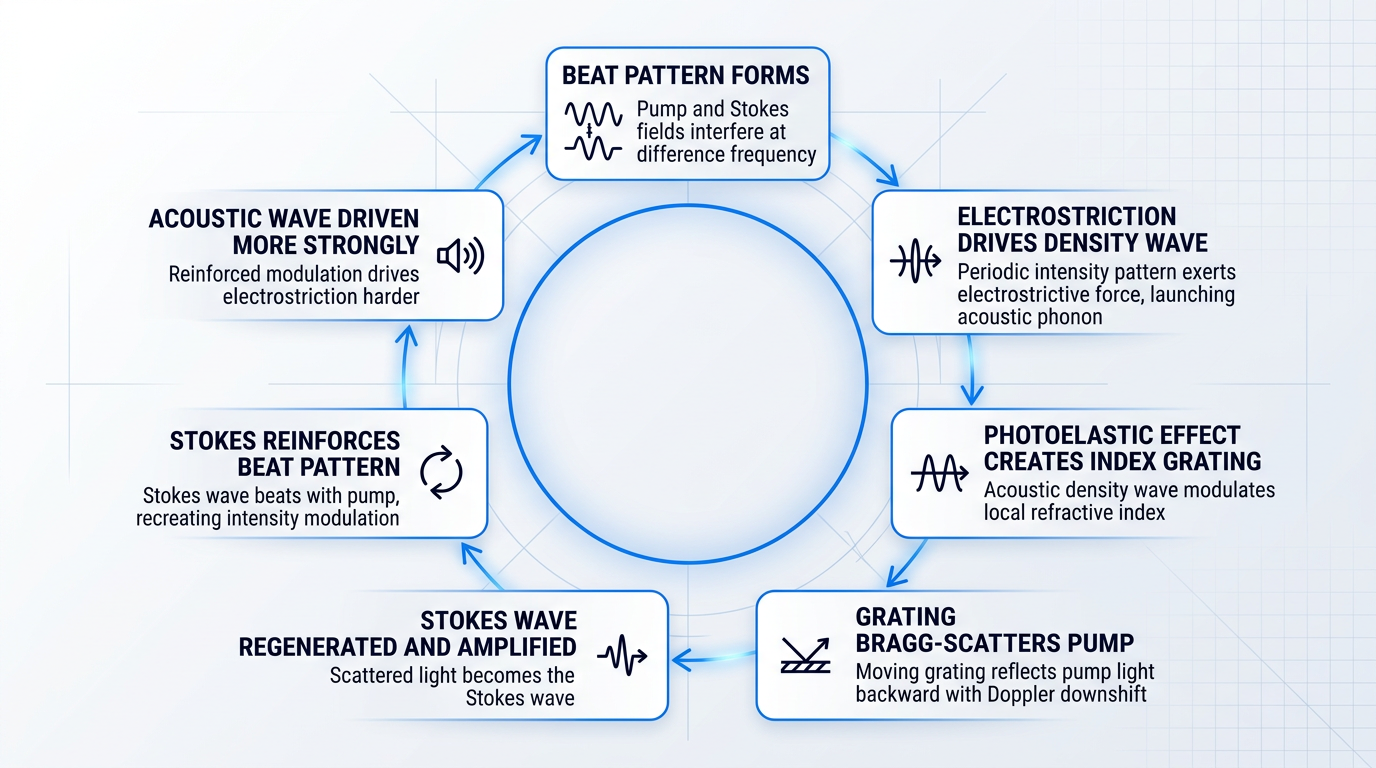
- Beat pattern forms: The pump field and any seed Stokes field — even spontaneous noise — interfere to create a periodic intensity modulation at their difference frequency.
- Electrostriction drives a density wave: The periodic intensity pattern exerts an electrostrictive force on the dielectric, launching a travelling acoustic phonon at the beat frequency.
- Photoelastic effect creates an index grating: The acoustic density wave modulates the local refractive index via the photoelastic effect, forming a travelling index grating moving at the acoustic velocity.
- Grating Bragg-scatters the pump: The moving grating reflects pump light backward with a Doppler downshift equal to the acoustic frequency, generating the Stokes wave.
- Stokes wave reinforces the beat: The Stokes wave beats with the pump, recreating an intensity modulation at exactly the same spatial frequency as the original beat pattern.
- Acoustic wave is driven more strongly: The reinforced intensity modulation drives electrostriction harder, amplifying the acoustic wave beyond its initial spontaneous level.
- Exponential growth above threshold: The cycle repeats: the acoustic amplitude and the Stokes field grow together, each sustaining the other — exponentially once the gain exceeds losses.
The self-reinforcing character of this loop rests on a precise spatial resonance: the Stokes wave, beating with the pump, recreates the exact intensity modulation — at the exact spatial frequency — needed to sustain the acoustic wave that produced it in the first place.
This is what distinguishes stimulated from spontaneous Brillouin scattering: the acoustic wave is not a pre-existing feature of the medium that the light happens to scatter from — it is co-generated by the optical fields and continuously reinforced by them.
Above threshold, the acoustic wave and the Stokes field do not exist independently — they are mutually created and mutually sustained. Remove one and the other collapses. This co-generative lock is what drives exponential gain.
A schematic of this cycle — pump interference driving an acoustic phonon, the phonon creating an index grating, and the grating regenerating the Stokes wave — makes the closed-loop structure immediately apparent.
Electrostriction is not the only mechanism by which optical fields can couple to acoustic modes. A second, physically distinct coupling pathway is radiation pressure — the mechanical force that a confined optical field exerts on the boundaries of the waveguide through optical gradient forces.
In standard silica optical fibres, electrostriction dominates and radiation pressure is a small correction. In nanoscale waveguides with subwavelength cross-sections, however, the optical field is tightly confined and its evanescent tail interacts strongly with the waveguide surfaces; boundary-induced radiation pressure becomes comparable to, or larger than, the electrostrictive contribution. Work by Rakich and colleagues demonstrated that this regime can yield giant enhancements in effective SBS nonlinearity relative to bulk fibre — a consequence of the intense surface forces at these dimensions.
The practical implication is that the dominant photon-phonon coupling mechanism is geometry-dependent: electrostriction governs SBS in bulk and large-core fibre, while radiation pressure can take over in nanoscale-confined waveguides, opening pathways to SBS nonlinearities far exceeding what silica fibre can achieve.
The overall strength of SBS in any given medium is also set by the material's intrinsic properties: specifically, its photoelastic tensor — which quantifies how strongly strain modulates the refractive index — and its electrostrictive coupling coefficient, which governs how efficiently the optical field drives density variations. Materials with large photoelastic response and strong electrostrictive coupling exhibit substantially stronger SBS than silica, a fact that underpins the interest in alternative material platforms for on-chip Brillouin devices.
The geometry of the acoustic phonon also determines which variety of SBS occurs. Backward SBS — the dominant process in standard optical fibres — involves longitudinal acoustic phonons propagating along the fibre axis, counter-directional to the Stokes wave. Forward SBS, by contrast, involves transverse acoustic modes that oscillate across the waveguide cross-section rather than along it, and produces a much smaller frequency shift.
In large-core fibres, transverse acoustic modes are poorly confined and forward SBS is typically negligible. In nanoscale waveguides, strong transverse confinement of both the optical and acoustic fields can make forward SBS significant — or even the dominant process. This geometry-driven distinction will be central to the discussion of waveguide-based Brillouin devices in a later section.
The direction of the Stokes wave — and whether the process is forward or backward — is not an accident of geometry but a consequence of phase-matching constraints imposed by momentum conservation, which the next section examines in detail.
Phase Matching and the Brillouin Frequency Shift
Phase matching is the selection rule that determines both the geometry of stimulated Brillouin scattering and the precise frequency at which it occurs — it is the reason SBS overwhelmingly produces a backward-propagating Stokes wave rather than a forward one, and the reason that Stokes wave sits at a very specific frequency offset from the pump.
The condition arises from momentum conservation: for the three-wave interaction to be efficient, the acoustic wavevector k_a must equal the vector difference between the pump wavevector k_p and the Stokes wavevector k_s, expressed as k_a = k_p − k_s.
The geometry of this vector equation is what separates backward SBS from forward SBS so decisively. For forward scattering, the pump and Stokes waves co-propagate, so their wavevectors nearly cancel — the required acoustic wavevector is close to zero, corresponding to a quasi-static density variation rather than a propagating acoustic phonon.
For backward scattering, the Stokes wave propagates antiparallel to the pump, so the difference k_p − k_s is approximately twice the optical wavevector magnitude, giving a large, well-defined acoustic wavevector that corresponds to a genuine propagating phonon at a frequency set by the acoustic dispersion relation.
Applying the acoustic dispersion relation to the backward phase-matching condition yields the Brillouin frequency shift formula directly: ν_B = 2n·v_a/λ.
Each parameter carries a clear physical meaning: n is the effective refractive index of the guided mode, which sets the optical wavelength inside the medium and therefore the magnitude of the optical wavevector; v_a is the longitudinal acoustic velocity in the fibre core material, which together with the acoustic wavevector determines the phonon frequency via the dispersion relation; and λ is the vacuum wavelength of the pump.
For standard single-mode silica fibre at a pump wavelength of 1550 nm, the Brillouin frequency shift is approximately 10.7–10.9 GHz — the IEEE 802.3av document cites 10.7 GHz as the canonical peak value, and multiple peer-reviewed measurements cluster around 10.8–10.9 GHz at this wavelength.
This places the Stokes wave roughly 10.8 GHz below the pump frequency — a fractional offset of only around 0.01%, yet large enough to be resolved directly with standard microwave-frequency electronics by beating the pump and Stokes signals on a fast photodiode, which is precisely what makes SBS practically measurable and exploitable.
The shift scales with pump wavelength via the 1/λ dependence in the formula: at 1064 nm, the Brillouin shift in silica rises to approximately 16.2 GHz, while near 1300 nm the shift falls in the range of roughly 11.5–13 GHz depending on the fibre refractive index profile.
| Pump Wavelength | Brillouin Frequency Shift | Source |
|---|---|---|
| 1064 nm | ~16.2 GHz | Fibre amplifier study (TIB/edocs) |
| 1300–1320 nm | ~11.5–13 GHz | BGS characterisation study |
| 1550 nm | ~10.7–10.9 GHz | IEEE 802.3av; peer-reviewed measurements |
Comparison of Brillouin frequency shift values in silica single-mode fibre across pump wavelengths, grounded in peer-reviewed and IEEE source data.
The 1/λ scaling is consistent across all three data points: the measured 16.2 GHz at 1064 nm sits exactly where the formula predicts relative to the 10.8 GHz baseline at 1550 nm, confirming that the formula is not merely empirical but a direct consequence of the phase-matching geometry.
Because ν_B = 2n·v_a/λ depends on both the refractive index and the acoustic velocity of the fibre core, every distinct fibre composition produces a measurably different Brillouin shift — making it a precise spectroscopic fingerprint of the material and its mechanical state.
Both n and v_a are sensitive to the physical state of the fibre, which transforms the Brillouin shift from a curiosity into a precision measurand. Temperature changes alter the refractive index via the thermo-optic effect and modify the acoustic velocity through thermal expansion; peer-reviewed measurements consistently report a temperature sensitivity of approximately 1 MHz/°C for standard silica SMF at 1550 nm.
Mechanical strain acts through the photoelastic and elasto-optic effects on both n and v_a; the strain sensitivity of the Brillouin shift in silica SMF is approximately 0.04–0.05 MHz/με at 1550 nm, with published values of 0.0483–0.0495 MHz/με reported across multiple independent studies.
Core composition also matters: germanium doping, standard in SMF-28-type fibres, modifies both the refractive index and the acoustic velocity relative to pure silica, shifting ν_B to a measurably different value — a fact exploited in fibre identification and sensing calibration.
These linear dependencies on temperature and strain are the physical foundation for distributed Brillouin sensing; the full treatment of how they are exploited in BOTDA and BOTDR systems follows later in this guide.
One important refinement to the formula concerns the refractive index term. In a waveguide, the relevant quantity is the effective mode index n_eff rather than the bulk material index, because the guided mode samples both core and cladding with a weighting set by the mode field distribution. For standard single-mode fibre this correction is modest, but in nanoscale waveguides on photonic chips — where the mode is strongly confined — n_eff departs significantly from the bulk value and the phase-matching condition must be evaluated accordingly.
A distinct phase-matching regime exists for forward SBS, where the co-propagating geometry means the longitudinal acoustic wavevector is near zero; instead, transverse acoustic modes with wavevectors perpendicular to the propagation axis can satisfy a confinement-mediated phase-matching condition, producing Brillouin shifts in the range of tens to hundreds of MHz — far lower than the ~10 GHz of backward SBS, and typically negligible in standard single-mode fibre but increasingly significant in nanoscale waveguides.
With the Brillouin frequency shift established from first principles, the natural next question is how strong the gain is at that frequency and what pump power is required before the Stokes wave grows exponentially — which is the subject of the gain spectrum and threshold conditions covered in the following section.
The SBS Gain Spectrum and Threshold Conditions
Knowing that SBS exists is one thing; knowing precisely how fast the Stokes wave grows and at what power it becomes catastrophic is what actually shapes system design. Two quantities govern both questions: the SBS gain spectrum, which determines how selectively the process amplifies a counterpropagating wave, and the threshold power formula, which sets the hard engineering boundary beyond which backscatter dominates.
The Lorentzian Gain Spectrum
The SBS gain as a function of frequency offset from the pump follows a Lorentzian profile, centred precisely at the Brillouin frequency shift established in the previous section.
In angular frequency terms, the gain takes the form g(Omega) = g_B · (Gamma_B/2)² / [(Omega − Omega_B)² + (Gamma_B/2)²], where Gamma_B is the acoustic damping rate and Omega_B is the Brillouin angular frequency — a form confirmed across multiple peer-reviewed treatments of stimulated Brillouin scattering.
The width of this Lorentzian is set by the acoustic phonon lifetime: in silica, the phonon lifetime is of the order of 10 ns, giving a Brillouin linewidth (FWHM) of approximately 15–17.5 MHz at 1.55 µm via the relation Delta-nu_B = (2pi·tau_B)^-1, with broader values up to ~50–100 MHz observed in fibres where inhomogeneous broadening or dopant profiles contribute.
The peak Brillouin gain coefficient g_B at line centre is a material property, expressible as g_B = 2pi·n^7·p_12² / (c·lambda²·rho·v_a·Delta-nu_B), where p_12 is the elasto-optic coefficient, rho is the material density, v_a is the acoustic velocity, and Delta-nu_B is the Brillouin linewidth — the canonical value for silica is approximately 5×10⁻¹¹ m/W, making it roughly 500 times larger than the Raman gain coefficient.
This coefficient sets the absolute scale of SBS susceptibility before fibre geometry enters the picture: it is the material's intrinsic figure of merit, and it cannot be engineered away by changing fibre dimensions.
The Brillouin gain in decibels accumulated over an interaction length L is given by G_B = 4.34 · g_B · I_p · L, where I_p is the pump intensity — this is the mathematical expression of the feedback loop described earlier, showing that a counterpropagating Stokes wave experiences exponential amplification proportional to both pump intensity and interaction length.
The Lorentzian shape has a critical practical consequence: the gain falls off sharply as the signal frequency deviates from Omega_B, so a source whose linewidth is narrower than the Brillouin bandwidth experiences the full peak gain g_B, while a broadband source spreads its power across frequencies where the gain is substantially reduced.
A narrow-linewidth source whose spectral width falls within the Brillouin bandwidth drives the acoustic wave coherently and sees the full peak gain g_B. A broadband source with linewidth far exceeding the Brillouin bandwidth has its effective gain diluted by the ratio of Brillouin bandwidth to pump linewidth — making SBS a hazard that bites hardest at precisely the sources most valued for coherence.
Defining and Calculating the SBS Threshold
The conventional SBS threshold is defined by the Smith criterion: the input pump power at which the backscattered Stokes power at the fibre input equals the transmitted pump power at the output, corresponding to a Brillouin gain of approximately 90 dB.
Other operational definitions exist — including criteria based on the second derivative of reflected power or a specified fractional change in transmission — but the equal-power / ~90 dB definition is the most widely cited and underlies the canonical threshold formula.
That formula is P_th ≈ 21 · b · A_eff / (g_B · L_eff), where the numerical prefactor 21 corresponds to the Smith criterion; the four parameters each carry distinct physical meaning and, crucially, different degrees of designer control.
| Parameter | Symbol | Physical meaning | Typical value / range |
|---|---|---|---|
| Effective mode area | A_eff | Cross-sectional area over which optical power is distributed; larger area means lower intensity for the same power, raising the threshold. | ~67–85 µm² (standard SMF at 1550 nm); hundreds to >1000 µm² (LMA fibre) |
| Peak Brillouin gain coefficient | g_B | Material figure of merit for SBS susceptibility; set by elasto-optic coefficient, density, acoustic velocity, and Brillouin linewidth. | ~5×10⁻¹¹ m/W for silica at 1550 nm |
| Effective interaction length | L_eff | L_eff = (1 − e^(−αL))/α; accounts for pump attenuation along the fibre. Saturates at 1/α for long fibres, limiting gain accumulation. | ~20 km maximum for α ≈ 0.2 dB/km (derived as 1/α); shorter for higher-loss fibre |
| Polarisation factor | b | Accounts for the relative polarisation state of pump and Stokes waves. Aligned polarisation gives the lowest threshold; scrambled polarisation doubles it. | 1 (aligned) to 2 (fully scrambled) |
| Smith criterion prefactor | 21 | Numerical constant derived from the condition that backscattered Stokes power equals input pump power (~90 dB Brillouin gain). Value varies slightly with threshold definition used. | 21 (Smith criterion); alternative definitions yield values in the range 16–25 |
Parameter-by-parameter breakdown of the SBS threshold formula, giving symbol, physical meaning, and typical values to support quantitative design decisions.
The table reveals a clear split between what is fixed and what is controllable: g_B is a material constant the designer cannot change, but A_eff, L_eff, and b are all amenable to engineering — larger mode area, shorter effective length, and polarisation scrambling each independently raise the threshold.
The saturation of the effective interaction length at 1/alpha deserves particular attention: for a standard silica fibre with loss alpha ≈ 0.2 dB/km, L_eff approaches roughly 20 km regardless of physical fibre length, because the pump is attenuated and distant sections of fibre contribute diminishing incremental gain.
When the pump linewidth Delta-nu_P exceeds the Brillouin bandwidth Delta-nu_SBS, the threshold scales as P_th ∝ (1 + Delta-nu_P / Delta-nu_SBS) — this linewidth correction is the quantitative basis for spectral broadening as a mitigation strategy, since doubling the pump linewidth relative to the Brillouin bandwidth approximately doubles the threshold.
The correction is a direct consequence of the gain-linewidth product: broadening the pump spreads power across frequencies where the Lorentzian gain is reduced, diluting the peak gain that any single frequency component experiences.
This creates a genuine physical trade-off with no easy resolution: narrow-linewidth sources are the most SBS-susceptible, yet they are also the most desirable for coherent communications, precision sensing, and coherent beam combining — and linewidth broadening that raises the threshold simultaneously degrades the coherence that makes those applications possible.
High-power narrow-linewidth erbium-fibre amplifiers operating in the C-band sit at the sharpest point of this tension, with the threshold formula directly constraining their architecture — which is why our custom EDFA from Woodrow Scientific Limited is engineered end-to-end to the application, with SBS management treated as a first-order design input rather than an afterthought.
With the gain spectrum and threshold formula now established, the natural next question is why the geometry of optical fibres makes these parameters so unfavourable — the subject of the following section on fibre confinement, effective length, and susceptibility.
SBS in Optical Fibres: Confinement, Effective Length, Susceptibility
The parameters in the threshold formula are not abstract quantities — they are determined by specific fibre properties, and those properties conspire to make optical fibre one of the most SBS-susceptible environments in all of photonics.
Three characteristics act together to create this susceptibility: the fibre's small core confines light to an intensity that diffraction prevents in bulk media; the waveguide structure supports interaction lengths of kilometres rather than millimetres; and low propagation loss preserves both the pump and the backward-growing Stokes wave across that entire distance.
Each factor alone would elevate SBS susceptibility; together they produce a qualitatively different regime, not merely a quantitative improvement over bulk.
In bulk media, diffraction imposes a hard ceiling on the useful interaction length: the Rayleigh range of a focused beam — typically millimetres to centimetres for practical spot sizes — is all the distance the pump and Stokes wave share before the beam diverges and intensity collapses.
A bulk medium also provides no structural enforcement of the backward-propagating geometry: the waveguide boundary conditions that make backward phase-matching so efficient in fibre are simply absent, so the gain process is both shorter and geometrically less favourable.
The effective mode area (A_eff) is set by the core diameter and numerical aperture: a smaller core confines the guided mode to a tighter cross-section, so the same optical power produces a proportionally higher intensity, driving the electrostrictive acoustic excitation harder and reducing the power needed to reach threshold.
The effective interaction length (L_eff) is governed by fibre loss and physical length through the relation L_eff = (1 − e^(−αL))/α: as loss increases, the pump is attenuated before it can sustain Brillouin gain over the full physical path, so L_eff saturates at 1/α in the long-fibre limit.
The practical consequence is that ultra-low-loss fibres are the most vulnerable: their effective length approaches their physical length, and kilometres of coherent pump-Stokes interaction become available to the gain process.
The Brillouin gain coefficient g_B is a material property determined by core composition: dopants such as germanium, phosphorus, fluorine, and aluminium each modify the acoustic velocity and photoelastic coupling constants, shifting both the peak gain and the Brillouin frequency, and providing a material-level handle on susceptibility alongside the geometric factors.
Mode Structure and SBS Susceptibility
Single-mode fibre (SMF) is the most susceptible geometry because only the fundamental mode is guided: the full Brillouin gain coefficient applies to a single pump-Stokes mode pair, with no averaging across modal populations.
This is the structural tension at the heart of coherent fibre systems — single-mode operation, which is essential for narrow linewidth and high coherence, is also the configuration that maximises SBS gain.
The coupled-mode equations for fibre SBS capture this geometry precisely: the pump wave loses power as it propagates forward (depleted by Stokes generation), while the Stokes wave grows exponentially as it propagates backward through the pump field, with the acoustic wave mediating the energy exchange between them.
These equations are the mathematical backbone from which the threshold formula and gain spectrum in §6 are derived — they describe a coupled energy transfer between two counterpropagating optical waves, sustained and directed by the acoustic field the pump itself excites.
The same properties that make single-mode fibre ideal for coherent transmission — tight confinement, low loss, and long interaction length — are precisely the conditions that minimise the SBS threshold. Susceptibility is not a flaw in the fibre design; it is the direct, predictable consequence of the waveguide's strengths.
In multimode fibre, different mode pairs couple to different acoustic modes with slightly offset Brillouin frequencies, producing a form of modal averaging that broadens the effective gain spectrum and distributes gain across a wider bandwidth, raising the threshold compared with single-mode operation.
With the fibre's susceptibility understood in terms of its geometric and material parameters, the engineering question becomes how to modify those parameters — or work around them — to raise the threshold to operationally acceptable levels, which is the focus of the next section.
Managing SBS: Suppression Strategies and Trade-offs
Of all the nonlinear effects that constrain high-power fibre systems, stimulated Brillouin scattering arrives first — and in narrow-linewidth continuous-wave operation, it arrives well before self-phase modulation, four-wave mixing, or Raman scattering become relevant. The narrow Brillouin gain bandwidth of roughly 50–100 MHz means that any source with a linewidth inside that window experiences the full peak gain coefficient, making SBS the binding power constraint that shapes amplifier architecture from the outset.
The threshold formula established in the preceding sections makes the engineering levers explicit: raise A_eff, reduce g_B, shorten the effective interaction length, or broaden the pump linewidth relative to the Brillouin gain bandwidth. None of these levers is free, and no single lever is sufficient at the highest power levels.
Signal-Domain Approach: Linewidth Broadening
The most immediately accessible route to a higher SBS threshold is phase modulation to broaden the pump linewidth. The linewidth correction factor (1 + Δν_P/Δν_SBS) from the threshold formula means that spreading optical power across a spectrum wider than the Brillouin gain bandwidth directly reduces the peak gain the acoustic wave can access.
The principal modulation schemes each carry a different spectral signature: sinusoidal phase modulation produces discrete sidebands; pseudo-random binary sequence (PRBS) modulation generates a more uniform comb-like spectrum; white-noise phase modulation produces near-continuous Gaussian broadening; and flat-top spectrum broadening uses tailored waveforms to distribute power as evenly as possible across a defined bandwidth.
The cost is fundamental, not incidental: linewidth broadening degrades temporal coherence. For applications that depend on it — coherent beam combining, spectral beam combining, and precision interferometric sensing — this is not a solvable engineering problem with a clean workaround. The tension between SBS suppression and coherence is real, and no modulation scheme resolves it.
Fibre-Level Strategies: The Primary Engineering Levers
While linewidth broadening is convenient to implement, the most durable SBS suppression is built into the fibre itself — through mode area, acoustic design, and longitudinal variation of the Brillouin frequency shift. These fibre-level approaches address the physics directly rather than working around it at the signal level.
Large mode area (LMA) fibre addresses the A_eff term directly: a larger core reduces the optical intensity at any given power, raising the SBS threshold proportionally. The trade-off is modal — cores large enough to provide meaningful suppression support multiple guided modes, compromising beam quality.
The standard mitigation is bend-induced loss, which preferentially attenuates higher-order modes and can recover near-diffraction-limited output from an LMA fibre. This imposes constraints on coiling geometry and adds design complexity that cannot be ignored in compact or ruggedised deployments.
Acoustic mode engineering operates on g_B itself rather than on intensity. The approach involves designing the fibre's acoustic refractive index profile to minimise the spatial overlap integral between the optical mode and the acoustic mode — a fibre in which the optical and acoustic fields occupy different spatial regions couples to the acoustic wave far less efficiently.
This is achieved through careful co-doping: phosphorus oxide raises the acoustic velocity in the core, while fluorine lowers it, allowing the acoustic velocity profile to be tailored largely independently of the optical refractive index profile. The result is a fibre that guides light normally while carrying a substantially reduced Brillouin gain coefficient — a materials and waveguide design solution, not a signal-processing one.
Fibre concatenation and longitudinal Brillouin shift variation attack the problem from a different angle. Concatenating segments with slightly different Brillouin frequency shifts — achieved by varying core composition or diameter along the length — broadens the effective SBS gain spectrum seen by the pump. Because the peak gain is reduced even when the total gain area is preserved, the threshold rises.
A continuously tapered fibre achieves the same effect in a single piece, avoiding splice losses between dissimilar segments. The trade-off in both cases is manufacturing complexity: producing fibre with a controlled, longitudinally varying Brillouin frequency profile is considerably more demanding than standard single-composition fibre.
Strain and temperature gradients offer a complementary route to longitudinal frequency variation without changing the fibre composition. Applying a longitudinal tensile strain shifts the local Brillouin frequency continuously along the fibre, broadening the effective gain spectrum and raising the threshold.
The practical limits are real: tensile strain in silica fibre is bounded by the mechanical failure threshold, which sits at a few percent elongation. Temperature gradients require thermal management infrastructure that may be impractical in compact or field-deployed systems. These techniques are useful additions to the toolkit, but they are not substitutes for fibre-level design in demanding applications.
Emerging Approach: Wavefront Shaping in Multimode Fibres
A more recent strategy involves selectively exciting many guided modes in a multimode fibre. Different optical mode pairs couple to different acoustic modes, distributing the Brillouin gain across a wider frequency range and raising the effective threshold. The challenge is maintaining output beam quality when multiple modes are excited simultaneously.
Wavefront shaping — using adaptive optics or spatial light modulators at the fibre input — can compensate for modal dispersion and recover near-diffraction-limited output. This approach is promising but not yet standard practice; it remains an active area of research rather than a proven production technique.
SBS Suppression Strategies Compared
The table below summarises the principal strategies, their suppression mechanism, primary trade-off, and the application contexts where each is most commonly deployed.
| Strategy | Suppression Mechanism | Primary Trade-off | Typical Application Context |
|---|---|---|---|
| Phase modulation (linewidth broadening) | Increases effective threshold via linewidth correction factor (1 + Δν_P/Δν_SBS) | Degrades temporal coherence; incompatible with coherent combining | High-power CW fibre amplifiers where coherence is not critical |
| Large mode area (LMA) fibre | Raises A_eff, reducing intensity and threshold power density | Multimode guidance; requires bend management for beam quality | High-power fibre lasers and amplifiers; industrial and defence systems |
| Acoustic mode engineering | Reduces g_B by minimising optical-acoustic mode overlap integral | Requires specialised co-doped fibre (P2O5, F); manufacturing complexity | Narrow-linewidth high-power systems where coherence must be preserved |
| Fibre concatenation / longitudinal Brillouin shift variation | Broadens effective SBS gain spectrum, reducing peak gain | Manufacturing complexity; splice losses between dissimilar fibre segments | High-power fibre amplifiers; tapered-fibre laser architectures |
| Strain / temperature gradients | Shifts local Brillouin frequency along fibre length, broadening gain spectrum | Strain limited by mechanical failure threshold; temperature needs thermal infrastructure | Laboratory and some industrial systems with available thermal management |
| Wavefront shaping in multimode fibres | Distributes gain across acoustic modes via multi-mode excitation | Beam quality recovery requires adaptive optics; not yet production-ready | Emerging research; high-power multimode fibre laser experiments |
Comparison of SBS suppression strategies by mechanism, primary trade-off, and application context
The table reveals a clear pattern: strategies that act on the fibre architecture — LMA design, acoustic mode engineering, longitudinal frequency variation — address the root cause of SBS susceptibility and preserve coherence, making them the preferred levers for systems where beam quality and coherence matter. Phase modulation is the fastest path to a higher threshold but forecloses options that depend on coherence. Strain and temperature approaches are useful supplements rather than primary solutions.
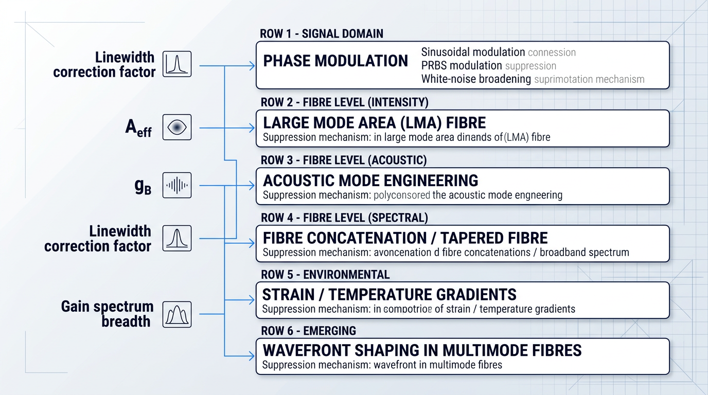
No single technique is sufficient at the highest power levels — this is the central engineering reality of SBS management.
At the highest power levels, effective SBS management requires combining fibre-level design (LMA, acoustic mode engineering, longitudinal frequency variation) with signal-level linewidth broadening and careful system architecture. Each lever addresses a different term in the threshold equation; only their combination moves the ceiling far enough.
This multi-lever reality is most acute in high-power narrow-linewidth erbium-fibre amplifiers — systems that must simultaneously push average powers above 100 W, pulse energies above 10 mJ, and peak powers above 100 kW while preserving the spectral and coherence properties the application demands. At these power levels, SBS is not an academic concern but a genuine design constraint that must be addressed before the amplifier architecture is fixed.
Woodrow Scientific Limited's Custom EDFA — developed and built in Southampton by WSL — illustrates precisely why end-to-end customisation matters here. An amplifier engineered to the application from the outset can incorporate SBS-mitigating fibre choices, appropriate mode area design, and system architecture suited to the power regime, rather than treating suppression as an afterthought to a fixed-catalogue platform.
The same physics that makes SBS a power-limiting challenge in amplifiers also makes it a remarkably precise and sensitive probe of the fibre environment — a duality that underpins an entire class of distributed sensing systems, explored in the next section.
SBS in Sensing: Distributed Temperature and Strain Measurement
Every suppression strategy covered in the preceding section treats the Brillouin frequency shift as a liability — something to broaden, dilute, or randomise away. Flip that perspective, and the same shift becomes one of the most powerful measurement tools in fibre optics: a built-in, continuous thermometer and strain gauge distributed along the entire fibre length.
The sensing principle rests on a linear relationship: in standard single-mode fibre at 1550 nm, the Brillouin frequency shift varies at approximately 1 MHz/°C with temperature and approximately 0.05 MHz/με with strain, with the exact coefficients depending on fibre composition and wavelength.
Physically, a local temperature rise increases the acoustic velocity and alters the refractive index, shifting the local Brillouin resonance upward; strain has an analogous effect through the elasto-optic response. Because these are local properties, interrogating the fibre with a pulsed optical signal and recording the Brillouin frequency shift as a function of time-of-flight maps those shifts onto position, yielding a continuous spatial profile — not a point measurement, but a full distributed sensing picture over the entire fibre length.
BOTDR and BOTDA: The Two System Architectures
Two dominant system architectures have emerged for interrogating this distributed Brillouin response, each with a distinct operating principle and a different set of practical trade-offs.
| Characteristic | BOTDR | BOTDA |
|---|---|---|
| Operating principle | Detects spontaneous Brillouin backscatter from a single pulsed input | Measures stimulated Brillouin gain between a pulsed pump and a counter-propagating CW probe |
| Fibre access required | Single-ended — one fibre end only | Dual-ended — both fibre ends must be accessible |
| Signal-to-noise ratio | Lower SNR; spontaneous scatter is weak | Higher SNR; stimulated gain is significantly stronger |
| Typical sensing range | Up to ~80 km demonstrated with EDFA assistance | Beyond 100 km demonstrated with amplified/coherent detection |
| Spatial resolution floor | ~1 m, set by phonon lifetime (~10 ns) | ~1 m, set by phonon lifetime (~10 ns) |
| Deployment complexity | Simpler; suited to remote, single-access installations | More complex; requires coordinated dual-end access |
Direct comparison of BOTDR and BOTDA across the key axes that govern deployment decisions: access requirements, signal basis, SNR character, and typical sensing range.
The practical consequence of this table is straightforward: BOTDA delivers superior SNR and supports longer sensing ranges, but the requirement for dual-end fibre access introduces installation complexity that can be prohibitive in remote or inaccessible infrastructure.
BOTDR, by contrast, needs only one accessible fibre end, which makes it the preferred choice for scenarios where running a return fibre path is impractical — long-distance pipeline monitoring, for instance, or sensing cables embedded in structures where one end is permanently sealed.
Spatial Resolution and the Phonon Lifetime Limit
Spatial resolution in both architectures is set by the optical pulse width: a shorter pulse localises the measurement to a smaller fibre segment, improving resolution.
There is, however, a hard lower bound. The phonon lifetime in standard silica fibre is approximately 9–10 ns, corresponding to roughly 1 metre of spatial resolution. A pulse shorter than the phonon lifetime cannot build up the acoustic phonon field efficiently — the phonon has insufficient time to reach steady state — which suppresses the Brillouin gain and degrades the measurement.
This is not an electronics or signal-processing bottleneck that better hardware can overcome; it is a direct consequence of the acoustic physics, and it sets a fundamental floor below which conventional time-domain Brillouin sensing cannot go.
The ~9 ns phonon lifetime in silica fibre constrains conventional BOTDR and BOTDA to approximately 1 metre of spatial resolution. No improvement in pulse electronics or signal processing can remove this limit — it is an intrinsic property of the acoustic phonon field.
Several research-level techniques have been developed to push spatial resolution below this floor, each bypassing the phonon lifetime constraint through a different mechanism.
- Differential pulse-pair BOTDA: Two pulses of slightly different lengths are fired; subtracting the responses localises gain to a thin slice shorter than the phonon lifetime.
- Synthetic BOTDR (S-BOTDR): A spectral synthesis approach that has experimentally demonstrated 10 cm spatial resolution, far below the conventional 1 m floor.
- Slope-assisted methods: Sub-pulse-length events are detected by monitoring the slope of the Brillouin gain spectrum rather than tracking the peak frequency shift.
These techniques represent active research directions rather than commercially mature capabilities; they typically trade sensing range for resolution, and deployment at scale remains an open engineering challenge.
The Strain-Temperature Cross-Sensitivity Problem
Because the Brillouin frequency shift responds to both temperature and strain simultaneously, a single measurement cannot unambiguously attribute an observed shift to one source or the other — a 1 MHz increase could reflect a 1 °C temperature rise, a 20 με strain increase, or some combination of both.
This cross-sensitivity is a fundamental ambiguity, not an instrument artefact, and it must be addressed at the system design level before distributed Brillouin sensing can deliver reliable absolute measurements in environments where both quantities vary.
The most direct approach is the reference fibre method: a second fibre is installed in parallel, mechanically decoupled from the structure so it responds to temperature alone, providing the temperature profile needed to subtract the thermal contribution from the total measured shift in the primary fibre.
A more elegant solution exploits fibres that support multiple acoustic modes — such as few-mode fibres — where different modes carry different temperature and strain sensitivity coefficients. Because the two modes provide two independent equations in two unknowns (ΔT and Δε), simultaneous discrimination becomes possible from a single fibre measurement; few-mode BOTDA systems have demonstrated temperature accuracy of approximately 1.2 °C and strain accuracy of approximately 22 με using this approach.
The range-resolution trade-off adds a further constraint on real-world deployments: maintaining adequate SNR over longer fibre spans requires longer pump pulses, which degrades spatial resolution. Practical BOTDA systems routinely achieve metre-scale resolution over tens of kilometres; extending range beyond 100 km, as demonstrated in research configurations using distributed amplification or coherent detection, typically comes at the cost of several-metre resolution.
The application domains that have matured around these capabilities are correspondingly diverse. In structural health monitoring, a single sensing fibre bonded to a bridge deck, tunnel lining, or dam face can replace thousands of discrete point sensors, providing a continuous strain profile that reveals deformation patterns invisible to conventional instrumentation — the Streicker Bridge at Princeton is among the documented field deployments. In the energy sector, distributed Brillouin sensing monitors power cables for thermal hot spots that precede insulation failure, and provides downhole temperature profiling in oil and gas wells. Geophysical applications include landslide detection, permafrost monitoring, and railway track integrity assessment, where the fibre's kilometre-scale reach and sensitivity to millimetre-scale deformation are particularly valuable.
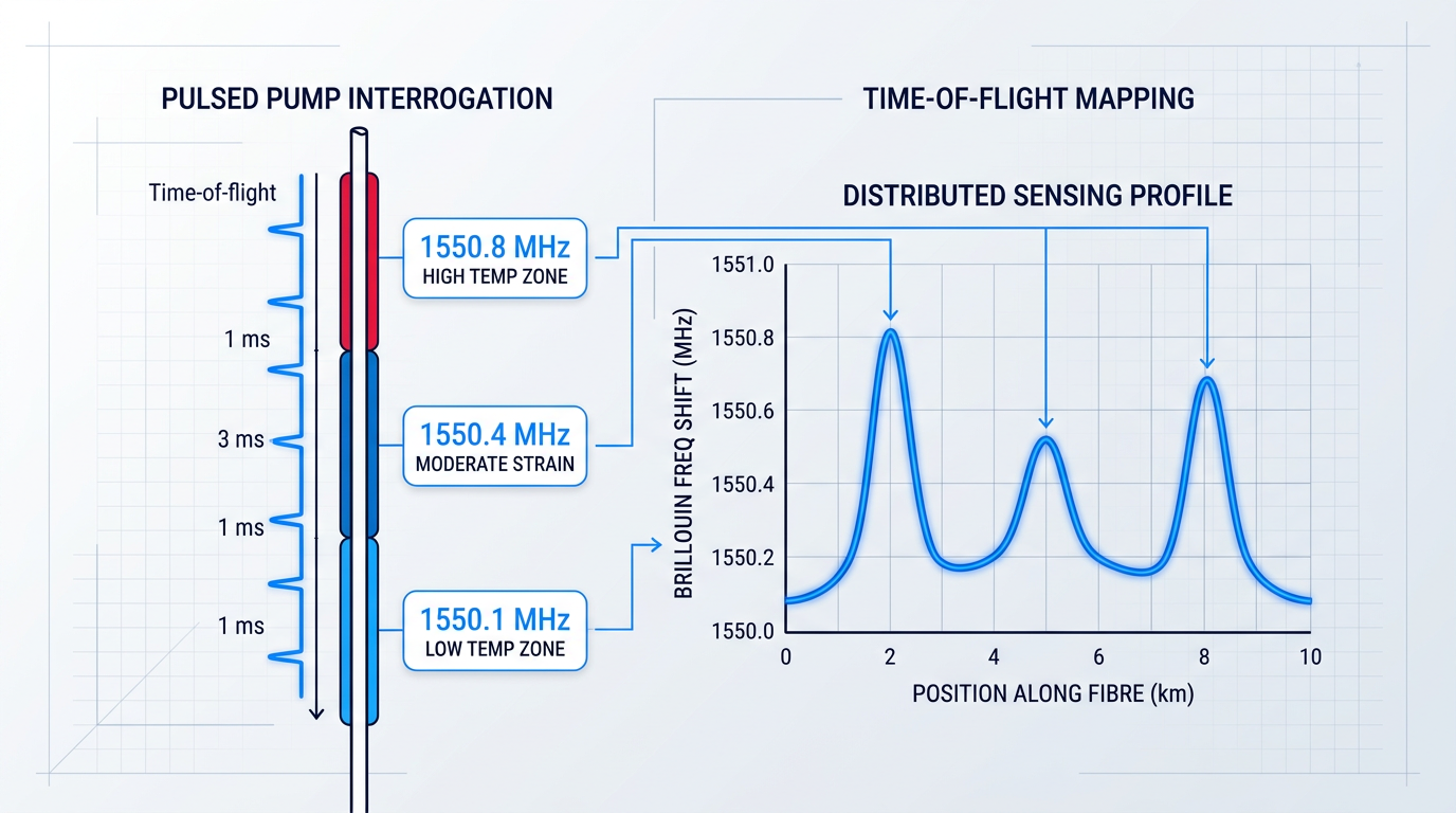
Distributed Brillouin sensing exploits SBS across kilometre-scale fibre lengths, where the phonon lifetime and fibre propagation physics define the fundamental performance envelope. The next section moves to the opposite extreme: chip-scale photonic structures where tight optical and acoustic confinement opens an entirely different regime of SBS exploitation, enabling ultra-narrow linewidth Brillouin lasers and new classes of signal-processing devices.
SBS in Photonic Integration and Brillouin Lasers
The preceding sections of this guide have treated stimulated Brillouin scattering largely as a constraint — something to model, threshold, and suppress. This section inverts that framing entirely. On photonic integrated platforms, SBS is increasingly the goal: a precision nonlinear interaction that enables capabilities no other on-chip effect can replicate.
Confinement, Phonon Leakage, and the On-Chip SBS Challenge
Scaling SBS from optical fibre to a photonic waveguide is not simply a matter of reducing the mode area to increase optical intensity. Strong SBS requires simultaneous confinement of both photons and phonons within the waveguide core — the governing quantity is the overlap integral between the optical and acoustic mode fields, and that integral collapses if the acoustic wave leaks into the surrounding substrate.
This is precisely the failure mode of conventional silicon-on-insulator (SOI) waveguides: silicon confines light tightly, but phonons at gigahertz frequencies leak readily into the silica undercladding, which acts as an acoustic continuum. The photon-phonon overlap integral is severely degraded, and SBS is suppressed despite the high optical intensity — driving the need for suspended membrane structures and phononic crystal claddings that physically isolate the acoustic field.
At subwavelength dimensions, a second physical shift occurs. In standard silica fibre, as established earlier in this guide, electrostriction is the dominant photon-phonon coupling mechanism. In high-index-contrast nanoscale waveguides, boundary-induced radiation pressure — the optical force exerted on the waveguide walls by the confined optical field — becomes comparable to or dominant over electrostriction. Research on hybrid phononic-photonic silicon waveguides has demonstrated forward-SBS nonlinear susceptibilities over 3,000 times stronger than any prior waveguide system, with simulations confirming that a constructive combination of electrostrictive forces and radiation pressure at the nanoscale is responsible for this giant enhancement.
Material Platforms for On-Chip Brillouin Interactions
Platform choice is the primary engineering lever for on-chip SBS: the material determines the intrinsic Brillouin gain coefficient, the acoustic velocity, and whether simultaneous optical and acoustic confinement is achievable within a practical waveguide geometry.
- Chalcogenide glass: As₂S₃ and As₂Se₃ offer inherently large Brillouin gain coefficients — the first on-chip SBS demonstration used a 7 cm As₂S₃ rib waveguide, measuring a gain coefficient of ~0.7 × 10⁻⁹ m/W with a 16 dB probe gain at ~300 mW pump power.
- Silicon (hybrid designs): Standard SOI suppresses SBS via phonon leakage. Suspended anti-resonant acoustic waveguides (SARAWs) on SOI have achieved Brillouin gain coefficients exceeding 3,500 W⁻¹m⁻¹ — over 2,000 times larger than standard single-mode fibre — with net gain thresholds below 5 mW.
- Silicon nitride with TeO₂: Depositing a tellurium oxide (TeO₂) layer onto Si₃N₄ waveguides enables surface acoustic wave SBS with a gain coefficient of 81 W⁻¹m⁻¹ — a two-orders-of-magnitude improvement over bare silicon nitride — while retaining CMOS-compatible fabrication.
These three platforms reveal a consistent trade-off: chalcogenide delivers the highest intrinsic gain but faces integration-compatibility constraints; silicon requires structural engineering to solve the phonon confinement problem but benefits from mature semiconductor fabrication; and the Si₃N₄/TeO₂ platform bridges strong gain with low propagation loss and scalability, demonstrated by 5 dB net optical gain in a 6.7 cm waveguide.
A subtler constraint applies across all platforms: the acoustic decay length of roughly 100 µm sets a practical floor on useful waveguide length for backward SBS. Sub-millimetre waveguides see reduced Stokes gain and broadened acoustic resonances because the acoustic mode requires several decay lengths to build up to its nominal value — a finding confirmed in detailed modelling of short high-gain structures. This is one of the principal reasons that microresonator geometries, which substitute resonant enhancement for long propagation length, are attractive for Brillouin lasing.
Brillouin Lasing in High-Q Microresonators
In a high-Q optical microresonator, the circulating optical field accumulates interaction length with each round trip, dramatically amplifying the effective SBS gain. The critical design constraint is that the free spectral range (FSR) of the cavity must be matched to the Brillouin frequency shift, so that the Stokes wave falls on a cavity resonance and experiences coherent feedback — without this alignment, the Stokes field does not build up efficiently.
Resonant enhancement reduces the lasing threshold from the watt-level typical of short straight waveguides to milliwatts or below in high-Q cavities. A chalcogenide microresonator designed with an FSR of 7.74 GHz matched to the As₂S₃ Brillouin phonon frequency achieved a lasing threshold of 0.53 mW — approximately 100 times lower than prior chalcogenide on-chip records. A visible-light Si₃N₄ ring resonator Brillouin laser with a Q of 55.4 million demonstrated a 14.7 mW threshold and 269 Hz linewidth, with the ring FSR set to 1/7 of the 25.110 GHz Stokes shift.
Cascaded Stokes generation is a natural consequence of the microresonator geometry: once the first Stokes wave reaches sufficient power, it acts as a pump for a second Stokes wave, and so on, producing a Brillouin frequency comb with GHz line spacing set by the acoustic properties of the medium. This cascading is both a feature — enabling broadband comb generation — and a complication, since uncontrolled cascading limits output power and degrades noise performance of the primary lasing mode.
The headline capability of Brillouin microresonator lasers is linewidth below 1 Hz, demonstrated experimentally by the Vahala group at Caltech. More recently, a photonic integrated coil-resonator Brillouin laser in Si₃N₄ demonstrated a fundamental linewidth of 31 mHz with 41 mW output power and 73 dB sidemode suppression ratio — representing greater than five orders of magnitude frequency noise reduction from the free-running pump laser.
The pump laser's phase noise is transferred to the acoustic phonon field, but the phonon lifetime acts as a low-pass filter: high-frequency phase noise components of the pump are not efficiently imprinted onto the acoustic wave, and the Stokes wave inherits only the low-frequency noise that does pass through. Cavity feedback further suppresses the Stokes linewidth toward the Schawlow-Townes limit of the Brillouin gain medium — which, given the narrow gain bandwidth and high Q, can be extraordinarily low. The result is a Stokes output far quieter than the pump that drives it.
This linewidth-narrowing mechanism is not incidental — it is the physical reason Brillouin lasers are pursued as local oscillators and reference sources where phase noise performance is the primary figure of merit.
On-Chip SBS: Signal Processing and Beyond
Brillouin lasing is the most visible application of on-chip SBS, but the same photon-phonon interaction underpins a broader set of signal-processing capabilities that are inaccessible to other integrated nonlinearities — primarily because SBS provides a gain or loss resonance with MHz-level linewidth tunable across a wide frequency range, a combination no electronic or photonic filter technology can otherwise match.
- Microwave photonic filtering: SBS gain and loss resonances enable notch and bandpass filters with MHz-scale linewidth and tuning ranges exceeding 30 GHz — demonstrated with >55 dB stop-band rejection on chalcogenide chips.
- RF signal processing: On-chip SBS supports true time delay, phase shifting, and frequency-selective amplification for microwave photonic systems, with ns-scale delays demonstrated at pump powers below 40 mW.
- Slow light and tunable delay: SBS gain resonances modify the group velocity of a signal, enabling tunable optical delay lines; chalcogenide chips have demonstrated group-index changes exceeding 130 in compact footprints.
- On-chip optical isolation: Non-reciprocal SBS interactions break time-reversal symmetry, enabling isolation without magneto-optic materials — silicon waveguide demonstrations have shown >38 dB isolation over bandwidths exceeding 125 GHz.
Taken together, these capabilities position on-chip stimulated Brillouin scattering as a uniquely versatile nonlinear platform: the same light-sound interaction that limits power in fibre amplifiers becomes, at chip scale, a precision tool for spectral filtering, signal delay, and non-reciprocal propagation.
The full arc of SBS — from its role as a threshold effect constraining fibre systems, through its exploitation in distributed sensing, to its emergence as a precision resource in integrated photonics — reflects a phenomenon that rewards deep understanding at every level of the technology stack, a synthesis the conclusion to this guide will draw together.
Conclusion
SBS: a phenomenon that demands understanding
The same feedback loop between light and sound that imposes hard power ceilings in narrow-linewidth fibre amplifiers also underpins kilometre-scale distributed sensing and the ultra-narrow linewidths of Brillouin lasers — constraint and capability rooted in identical physics.
Engineers who have internalised the threshold conditions and gain spectrum navigate that span deliberately; those who have not tend to encounter it as a surprise.
High-power system designers will find the most leverage in acoustic mode engineering and multi-lever suppression; sensing practitioners in BOTDA architecture and advanced spatial resolution; those on photonic integration in chip-scale Brillouin physics, where the rules shift and the possibilities are still being written.
Frequently asked questions about stimulated Brillouin scattering
These answers address the practical clarifications and edge cases most likely to arise after reading the guide — each one is self-contained and can be read independently.
SBS involves acoustic phonons at GHz frequencies; SRS involves optical phonons at THz frequencies. This single difference drives nearly every practical distinction between them. In silica fibre, the SBS gain bandwidth is only about 50–100 MHz FWHM, while the SRS gain bandwidth spans tens of THz. Because SBS gain is concentrated in such a narrow spectral window, any source with a linewidth narrower than the Brillouin bandwidth experiences the full peak gain — this is why SBS has a significantly lower threshold than SRS in narrow-linewidth CW fibre systems. For broadband or short-pulse sources, spectral averaging dilutes the SBS gain across the source bandwidth, and pulse-width effects further suppress it, making SRS the dominant nonlinearity in those regimes.
Phase-matching conditions in a single-mode fibre are satisfied only for counterpropagating pump and Stokes waves. The underlying requirement is momentum conservation: the acoustic wavevector must equal the difference between the two optical wavevectors. For counterpropagating waves, this difference is approximately twice the optical wavevector, corresponding to a real, propagating acoustic wave at a well-defined GHz frequency. For co-propagating waves, the required acoustic wavevector would be near zero — corresponding to a near-zero acoustic frequency, essentially a DC displacement rather than a propagating phonon. No propagating phonon means no Brillouin gain. This is a consequence of single-mode waveguide geometry, not a material-specific property of silica.
The conventional definition is the input pump power at which the reflected Stokes power equals the transmitted output power — that is, half the input power is being scattered back. This is the most widely cited definition and is the basis for the canonical threshold formula P_th ≈ 21 · b · A_eff / (g_B · L_eff). In practice, two alternative measurement criteria are also used. The second-derivative method identifies the threshold as the inflection point in the curve of reflected power versus input power — it is more sensitive and detects threshold onset earlier than the equal-power criterion. The 4% reflected-power criterion, sometimes preferred in telecommunications contexts, defines threshold as the input power at which backscattered Stokes power reaches 4% of the input. Each definition is internally consistent, but they yield numerically different threshold values for the same fibre — so the measurement method should always be stated alongside any quoted threshold figure.
In standard single-mode silica fibre at 1550 nm, the Brillouin frequency shift is approximately 10–11 GHz, with typical values cited around 10.5–10.8 GHz. The shift is given by ν_B = 2nv_a/λ, where n is the refractive index, v_a is the acoustic velocity in the fibre core, and λ is the vacuum wavelength — any change in n or v_a moves the shift. Temperature raises the acoustic velocity slightly, increasing the shift by approximately 1 MHz per °C. Strain raises both the effective acoustic velocity and refractive index, shifting the frequency by roughly 0.05 MHz per microstrain. Fibre composition also matters: germanium, phosphorus, or aluminium doping changes both acoustic velocity and refractive index, so SMF-28, dispersion-shifted fibre, and photonic crystal fibre each carry measurably different Brillouin shifts. This sensitivity to temperature and strain is precisely what makes the Brillouin shift a useful measurand in distributed sensing systems such as BOTDA and BOTDR.
Yes, forward SBS can occur, but it involves a fundamentally different class of acoustic modes — transverse or radial guided acoustic modes rather than the longitudinal travelling-wave phonons responsible for backward SBS. In standard single-mode fibres it is typically much weaker: the phase-matching condition for forward SBS requires a near-zero acoustic wavevector, corresponding to transverse acoustic modes near their cut-off frequencies, which have poor spatial overlap with the optical mode in large-core fibres. Forward SBS becomes significant in two specific regimes. In nanoscale or subwavelength waveguides, simultaneous tight confinement of photons and phonons changes the phase-matching geometry, and forward inter-modal SBS involving guided acoustic modes can become the dominant process. In polarisation-maintaining fibres, inter-modal forward SBS between the two polarisation modes has been exploited to build forward-SBS lasers. Both are genuine effects, but forward SBS remains secondary to backward SBS in the vast majority of practical fibre systems.
For pulse widths shorter than the phonon dephasing time — approximately 10–20 ns in silica fibre — SBS gain is significantly reduced because the acoustic wave does not have time to build up to its steady-state amplitude during the pulse. The phonon lifetime in silica is of order 10 ns, which corresponds to the ~50–100 MHz Brillouin linewidth via the time-bandwidth product. Pulses much shorter than this do not drive the acoustic wave to full amplitude, so the effective Brillouin gain is reduced proportionally. Quantitatively, for pulse widths τ_p much shorter than the phonon lifetime τ_ph, the effective SBS gain scales approximately as τ_p/τ_ph — a 1 ns pulse sees roughly 10–20 times less SBS gain than a CW source at the same peak power. This is why SBS is primarily a concern for CW and long-pulse fibre systems, not for ultrafast or sub-nanosecond pulsed sources.
Chalcogenide glasses — particularly As₂S₃ and As₂Se₃ — have Brillouin gain coefficients orders of magnitude higher than silica, making it possible to achieve useful SBS gain in centimetre-scale on-chip waveguides rather than the kilometre-scale fibre lengths required in silica. The high gain coefficient arises from strong photoelastic coupling and high refractive indices, both of which amplify the electrostrictive contribution to the Brillouin interaction; lower acoustic velocities also shift the Brillouin frequency to a lower value and concentrate the gain. In practice, a centimetre-length chalcogenide waveguide can deliver gain equivalent to hundreds of metres of silica fibre, which is what makes chalcogenide the leading material platform for on-chip Brillouin signal processing, including narrow-band microwave photonic filters and on-chip Brillouin lasers. The trade-off is real: chalcogenide waveguides carry higher propagation loss than silica and are not CMOS-compatible, limiting direct integration with standard silicon photonics. Hybrid approaches — silicon nitride waveguides with chalcogenide overlayers — are one active route to combining low propagation loss with high Brillouin gain.