


Introduction
Every amplifier on this list flies aboard a spacecraft — ground-station and terrestrial EDFAs operate under an entirely different set of constraints and are out of scope here.
The term space qualified carries a precise meaning on this page: hardware that has completed a formal qualification test campaign covering radiation tolerance, thermal vacuum, vibration, and shock.
Hardware assembled from space-grade components but never subjected to that campaign is not space qualified — a distinction that matters considerably when a payload cannot be retrieved for repair.
TL;DR
Being marketed for space and being genuinely qualified for it are not the same thing. Across the specialist suppliers covered here, the gap between claimed and demonstrated qualification depth — in TRL, in-orbit heritage, and SWaP — is wider than most procurement shortlists acknowledge.
This article covers:

Space qualified vs space grade: the key distinction
Comparison axes: TRL, output power, NF, SWaP, heritage
EDFA, Er/Yb, and SOA technology types evaluated
SWaP constraints for CubeSat and small satellite programmes
Mission heritage as evidence, not a marketing claim
Five specialist suppliers assessed across LEO, MEO, GEO
Why Space Optical Amplifiers Demand Qualification Depth
Optical amplifiers have flown in space before — but the scale and urgency of demand is now categorically different, driven by a convergence of optical inter-satellite links (ISLs), optical feeder links, and direct-to-Earth laser communications from LEO constellations that collectively require compact, flight-qualified amplifiers aboard the spacecraft itself.
The ESA ScyLight optical roadmap identifies ISLs, GEO-ground feeder links, and direct LEO-to-ground optical downlinks as the core application drivers, with major satellite operators expressing interest in optical technology across GEO-GEO, GEO-LEO, MEO-MEO, and LEO-ground link architectures.
NASA's 2025 OFC plenary (Robinson, MIT Lincoln Laboratory) reinforces this picture: operational LEO constellations are already deploying optical ISLs at scale, and the agency's own roadmap identifies high-power space-based optical amplifiers in the 1550 nm band as a critical enabling technology gap for next-generation deep-space and near-Earth links.
What the Space Environment Does to Optical Amplifiers
The space environment imposes physical constraints that have no terrestrial analogue and that disqualify most commercial optical amplifier hardware outright — not as a matter of additional testing, but of fundamental design.
- Total Ionising Dose (TID): Cumulative ionising radiation from trapped protons and electrons degrades gain in doped fibre and induces threshold shifts in semiconductor drive electronics.
- Displacement Damage: Proton bombardment causes lattice displacement in semiconductor pump laser diodes, increasing threshold current and degrading output power over mission life.
- Single-Event Effects (SEE): Individual high-energy particles can trigger upsets, latchup, or burnout in control electronics — effects shielding alone cannot reliably mitigate.
- Thermal Vacuum Operation: Without convective cooling, amplifiers must conduct all waste heat conductively to a spacecraft panel — a constraint that directly shapes form factor and efficiency targets.
- Launch Vibration and Shock: Fibre splices, doped fibre coils, and pump-to-fibre couplings must survive launch mechanical loads without optical performance degradation.
The ESA Radiation Hardness Assurance framework (ECSS-Q-ST-60-15C) addresses TID, displacement damage (TNID), and SEE as the three primary radiation effect categories that must be assessed for all space projects — and each one maps directly onto a failure mode in optical amplifier subsystems.
Research conducted under the ESA high-efficiency optical amplifier project confirmed that gamma radiation produces significant gain degradation in commercial EDFA devices, with the doped fibre identified as the most critical optical component — the source of degradation in most of the devices tested.
Qualification Frameworks and Procurement Risk
Three qualification frameworks appear across the entries in this comparison, and understanding their differences is the fastest way to read procurement risk correctly.
ESCC (European Space Components Coordination) is the European framework for space component qualification, administered under ESA authority. Components that complete the full ESCC process are listed on the ESCC QPL (Qualified Parts List) — a status that, per ESCIES documentation, provides a general and long-term authorisation for use in space, independent of mission type, and follows a simplified procurement screening flow.
MIL-STD / MIL-PRF is the US defence and government equivalent, administered through the Defense Logistics Agency (DLA). Space-application device classes (such as Class V under MIL-PRF-38535) carry Radiation Hardness Assurance designators and are the standard qualification reference for US government and defence programmes.
The TRL scale (Technology Readiness Level, per ESA's ISO 16290-aligned definitions) provides a cross-agency maturity signal. For procurement decisions, the relevant levels are TRL 8 — "actual system completed and accepted for flight" (flight qualified) — and TRL 9 — "actual system flight proven through successful mission operations."
These frameworks translate into three distinct procurement risk tiers that will recur throughout the entries below.
- ESCC QPL-listed components: Highest confidence. Full manufacturer and component evaluation, qualification testing, and ESA certification. Simplified procurement screening; valid for two-year cycles with maintenance testing.
- Programme-specific qualification: Moderate confidence. Qualification is real and rigorous, but bespoke to a mission profile rather than independently certified against a standing standard.
- COTS with radiation characterisation: Lowest confidence. Radiation data exists but system-level qualification may be absent. Appropriate only where mission TID exposure and criticality are both low.
In an EDFA for space, the doped fibre is the component most sensitive to TID — radiation-induced gain degradation traces primarily to fibre composition rather than amplifier architecture, as the ESA high-efficiency optical amplifier project confirmed.
Suppliers who develop and control their own radiation-hardened doped fibre have a fundamental design advantage over those integrating commercial fibre into an otherwise space-qualified housing — a distinction that recurs across every entry in this comparison.
Technology Trade-Space at a Glance
EDFAs dominate C-band (1550 nm) space lasercom applications: the ESA high-efficiency amplifier project concluded they are clearly the best option on gain, output power, and bandwidth. Er/Yb co-doped fibre amplifiers extend to higher output powers through cladding-pumped architectures, making them the preferred route where multi-watt or tens-of-watts output is required.
Semiconductor optical amplifiers (SOAs) offer compactness but introduce nonlinear effects — cross-gain saturation and four-wave mixing — that limit their suitability for multi-channel or high-linearity applications, as confirmed by the ESA project testing.
The supplier landscape for space-qualified optical amplifiers is narrow: a small number of specialist photonics companies with genuine flight heritage, alongside broader photonics firms that have developed dedicated space product lines. This is not a commodity market, and the entries that follow reflect that reality — each supplier's qualification depth, fibre provenance, and mission record are the differentiators that matter.
Option 1
Exail — LNOA and Rad-Hard Doped Fibres
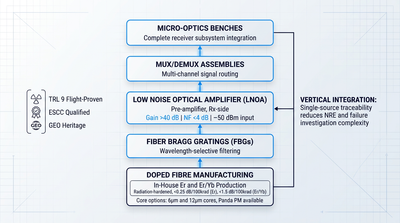
Exail (formerly iXblue) is a specialist space photonics supplier. Its LNOA targets Rx-side pre-amplification with >40 dB gain and <4 dB NF. TRL 9 components fly in GEO orbit; doped fibres are manufactured in-house.
Pros:

TRL 9 flight-proven components operating in GEO orbit
In-house doped fibre manufacturing: full vertical integration
Published gain degradation data: Er and Er/Yb
COTS to FM versions reduce NRE and schedule
Cons:

LNOA scoped to Rx-side low input power applications
IXF-NS radiation assessment is customer-performed, not Exail-certified
Company Background and Space Heritage
Exail was formed in October 2022 when ECA Group and iXblue joined forces under a shared brand. Programme documentation and heritage references predating that merger will use the iXblue name, so both are relevant when tracing qualification records and prior mission contributions.
The company's space photonics work is not a peripheral line within a generalist optics business. Exail's fibre-optic gyroscopes, specialty fibres, and electro-optical components have accumulated more than 6 million hours in orbit across the Astrix gyroscope programme alone, and the photonics division draws directly on that environmental qualification depth.
More than 200 LiNbO3 modulators currently flying in orbit, over 1,000 km of space-qualified optical fibre in operation, and components deployed on board satellites in GEO — the harshest radiation and thermal environment in commercial satellite operation.
Exail's space-grade optical components are qualified to ESCC standards and are compatible with missions from LEO through to GEO. Components sustain temperatures from -40°C to +85°C and operate at full performance between 0°C and +70°C.
LNOA Amplifier Performance
The Low Noise Optical Amplifier (LNOA) is designed specifically for very low input power scenarios on the receive side of an optical link, functioning as a pre-amplifier rather than a transmit-side power booster.
Exail publishes two headline optical performance figures for the LNOA: gain exceeding 40 dB at an input power of -50 dBm, and a noise figure below 4 dB. Both figures position the LNOA squarely in the pre-amplifier regime where receiver sensitivity is the critical design constraint.
The amplifier is available in single-channel and multi-channel configurations, with wavelength customisation offered as a main option. Its primary stated application is telecommunications for satellite constellations, specifically low-signal amplification on the Rx side.
The LNOA's design lineage traces to Exail's ASE sources developed for Fiber-Optic Gyroscopes already deployed in space, combined with fifteen years of radiation-resistant optical fibre development. That heritage informs both the component selection and the qualification approach rather than being a separate programme thread.
From a procurement standpoint, the LNOA is offered from COTS through to full Flight Model (FM) versions, with the explicit aim of reducing Non-Recurrent Engineering (NRE) costs and accelerating development timelines — a practical differentiator for programme teams working against constrained schedules.
Radiation-Hardened Doped Fibre Capability
Exail manufactures its own erbium (Er) and erbium/ytterbium (Er/Yb) doped fibres, which are the most radiation-sensitive active components inside any fibre amplifier. Controlling this element in-house means Exail holds full root-cause visibility if radiation-induced gain degradation is observed in programme.
| Fibre Type | Gain Degradation per 100 krad | Reference Amplifier Design |
|---|---|---|
| Erbium (Er) doped | < 0.25 dB / 100 krad | 30 dB gain EDFA |
| Erbium/Ytterbium (Er/Yb) doped | < 1.5 dB / 100 krad | 10 W amplifier design |
Published gain degradation performance for Exail's rad-hard doped fibre series, drawn from Exail's radiation-hardened space-grade doped fibres product page.
The rad-hard fibre series is compatible with cumulated irradiation doses up to 300 krad (3 kGy SiO2), covering the dose budgets of the most demanding GEO and long-duration LEO missions. Both 6 µm and 12 µm core options are available, with Panda PM and associated passive fibres also offered.
The significance for procurement teams is straightforward: an integrator sourcing doped fibre from a third party has limited diagnostic capability if radiation-induced performance degradation emerges in orbit. Exail's in-house fibre manufacturing closes that gap, providing engineering continuity from fibre composition through to amplifier-level qualification.
IXF-NS Series: New Space COTS Fibres
Alongside the fully qualified rad-hard range, Exail offers the IXF-NS series — a COTS fibre product line that uses an identical chemical composition to the RAD series, developed over fifteen years of R&D in doped fibres for radiative environments.
The distinction matters for procurement: the IXF-NS series carries Radiation Induced Attenuation (RIA) and Radiation Induced Gain Variation (RIGV) reference data, but the radiation assessment is performed by the customer rather than by Exail as part of a formal qualification programme. This transfers radiation risk to the buyer in exchange for COTS availability, stock pricing, and volume cost advantages suited to large constellation projects.
The IXF-NS range covers single-clad erbium (IXF-NS-AMP) for core-pumped ASE sources and amplifiers up to 200 mW, and double-clad Er/Yb (IXF-2CF-EY-NS) in 6 µm and 12 µm core variants for few-watt to 20 W amplifier and laser designs, available in both PM and non-PM configurations.
Vertical Integration and Engineering Continuity
Exail's space photonics portfolio spans the full amplifier stack in-house: radiation-hardened doped fibres, Fiber Bragg Gratings (FBGs), low noise optical amplifiers, MUX/DEMUX assemblies, and micro-optics benches. This vertical integration is uncommon among space photonics suppliers and has direct implications for programme support.
When Exail's LNOA flew as part of the TELEO geostationary optical transceiver — developed with Airbus Defence and Space and hosted aboard the Arabsat Badr-8 satellite — the doped fibre, the amplifier, and the associated micro-optic receiver components were all Exail-manufactured. That single-source traceability simplifies failure investigation and reduces inter-supplier coordination risk in flight qualification programmes.
Exail's space photonics qualification work has been conducted in collaboration with ESA, CNES, and Airbus Defence and Space across multiple programmes, including the ESA ARTES-funded FOLC and FOLC2 projects. That institutional collaboration record is relevant context for procurement teams evaluating supplier maturity alongside hardware specifications.
"This collaboration with Airbus marks a significant step forward for the deployment of optical technologies in space. The success of TELEO validates the performance of our TRL9 optical components and paves the way for future operational systems."
Option 2
Lumibird (Keopsys)

Lumibird's Keopsys Industries subsidiary is a European specialist in space-borne fibre amplifiers for OISL, offering HPA and LNA product families with documented heritage across ESA, CNES, and NASA programmes since 1997.
Pros:
Full LEO, MEO, and GEO orbital stack covered
Dual HPA and LNA in one package available
CubeSat-compatible modules offered for New Space
Critical components manufactured in-house at Lannion
Cons:
Gain block and OEM are separate configurations
Company Background and Vertical Integration
Keopsys Industries, based in Lannion, France, is the fibre laser and amplifier subsidiary of the Lumibird Group — formed through the October 2017 merger of the Keopsys and Quantel groups. The space amplifier products are designed, manufactured, and marketed under the Keopsys brand, with Lumibird SA as the consolidating parent.
Keopsys traces its origins to 1997, when Marc Le Flohic founded OptoComm Innovation in Lannion, which was subsequently renamed Keopsys. Space programme involvement is documented from that same period, and the company has accumulated programme relationships with ESA, CNES, and NASA over more than two decades.
A notable recent example of that agency engagement is the SOLiS consortium — a CNES-backed secure optical space link project under France's France 2030 programme — in which Keopsys by Lumibird participates alongside Thales Alenia Space, Safran, and Exail, targeting GEO optical communications demonstration.
On the vertical integration axis, Keopsys manufactures critical optical components in-house at Lannion: laser diodes, photodiodes, signal/pump combiners, and fibre Bragg gratings (FBGs). This full process control is a meaningful differentiator for procurement programmes that require supply chain continuity and engineering accountability at the component level.
Keopsys OISL Amplifier Range
Keopsys structures its space-borne OISL amplifier offer around two distinct product families serving opposite ends of the optical link.
| Family | Link Function | Key Performance Parameter | Technology |
|---|---|---|---|
| High Power Amplifier (HPA) | Tx booster — signal amplification before transmission | Output power up to 10 W, excellent OSNR | Er or Er/Yb doped fibre, single or dual stage |
| Low Noise Amplifier (LNA) | Rx pre-amplifier — weak signal amplification at receiver | Gain up to 60 dB, very low noise figure | Er or Er/Yb doped fibre, single or dual stage |
| Dual Amplifier Solution | Combined Tx and Rx in one package | Mass and cost optimisation for payload budgets | HPA and LNA integrated in same housing |
Keopsys OISL amplifier families: function, key performance parameter, and technology type for each product line.
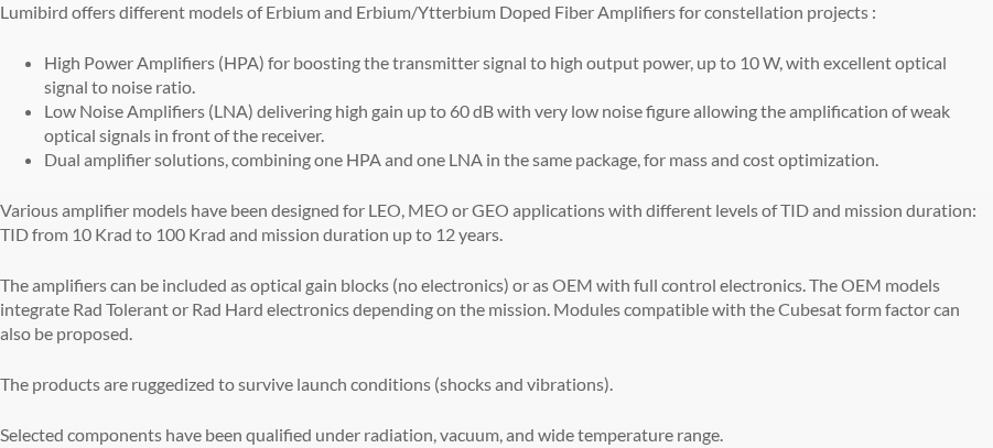
The HPA targets the transmitter side of an OISL, boosting the outgoing signal to output powers up to 10 W while maintaining excellent optical signal-to-noise ratio — a requirement for coherent links across inter-satellite distances.
The LNA addresses the receiver side: with gain up to 60 dB and a very low noise figure, it is designed to recover weak incoming signals before the coherent receiver, where sensitivity is the dominant link margin lever.
Both families are available in Erbium-doped and Erbium/Ytterbium co-doped configurations, in single-stage and dual-stage arrangements. The Er/Yb option enables higher output power via cladding pumping, which is why it appears in the HPA line alongside the standard Er-doped variant.
The dual amplifier solution — combining one HPA and one LNA in the same package — is a notable product-line feature for satellite payload integration, where combining two link functions into a single unit reduces both mass and unit cost relative to procuring separate modules.
Orbit Coverage and Radiation Tolerance
Keopsys designs amplifier models for LEO, MEO, and GEO applications — the full orbital stack. Models are differentiated by TID rating and mission duration: TID from 10 krad to 100 krad depending on the model, with mission duration qualification extending to up to 12 years.
CubeSat Compatibility and Form Factor
Keopsys explicitly offers modules compatible with the CubeSat form factor. The availability of CubeSat-compatible modules extends the product range beyond traditional GEO and large LEO bus programmes into smaller, cost-constrained platforms.
Control Electronics and Configuration Options
Two integration configurations are available: an optical gain block with no on-board electronics, for programmes that integrate the amplifier into their own electronics stack, and an OEM module with full control electronics for programmes that require a self-contained unit.
OEM models integrate either Rad Tolerant or Rad Hard electronics, selectable depending on the mission. This two-tier electronics qualification option accommodates the full range of orbital radiation environments the product line covers.
Ruggedisation and Environmental Qualification
Products are ruggedised to survive launch conditions, with shock and vibration qualification stated by Keopsys. Selected components are qualified under radiation, vacuum, and wide temperature range.
Keopsys by Lumibird participates in the CNES-backed SOLiS GEO optical communications consortium and has documented NASA engagement going back to early fibre amplifier development programmes at Goddard and JPL. That combination of European and US programme exposure, sustained across more than two decades, represents a broad agency footprint for a specialist fibre amplifier manufacturer.
Option 3
Nuphoton Technologies
US specialist fibre amplifier manufacturer since 1996, AS9100 certified, with NASA flight heritage including the Odysseus lunar lander mission. Space-qualified C-band EDFAs offer 100 krad radiation hardening and vacuum-rated operation.
Pros:
Flight-proven on NASA Odysseus lunar mission
100 krad radiation-hardened fibre and electronics
Vacuum-rated design to 7.5×10⁻⁵ torr
Customisable for programme-specific form and fit
Cons:
Operating temperature floor varies by published document
Nuphoton Technologies, headquartered in Murrieta, California, has been designing and manufacturing fibre lasers and amplifiers since 1996. The company holds AS9100 certification and, according to its published about-us page, the first laser communication link between Earth and a satellite demonstrated by NASA used a Nuphoton laser transmitter — a meaningful early heritage data point for a US-based specialist fibre amplifier manufacturer.
NASA Mission Heritage
Nuphoton's amplifier was a key component of the Doppler Navigation Lidar system aboard Intuitive Machines' Odysseus lunar lander, which completed a soft landing near the Moon's South Pole in February 2024 under NASA's CLPS initiative.
The Navigation Doppler Lidar, originally developed at NASA's Langley Research Center, provided precise altitude, speed, and direction data to the guidance, navigation, and control subsystems during landing — making the Odysseus mission a flight-proven demonstration of Nuphoton's amplifier hardware operating in a real mission environment.
Supporting this heritage is a separately documented programme: a MOPA-based 1550 nm fibre laser transmitter, built with Telcordia-rated components and developed in collaboration with NASA's Jet Propulsion Laboratory, has been in operation since its April 2014 launch, accumulating 30 months of documented service in low-earth-orbit optical communication.
EDFA-CW-C0-VRS-30-30-FCA Specifications
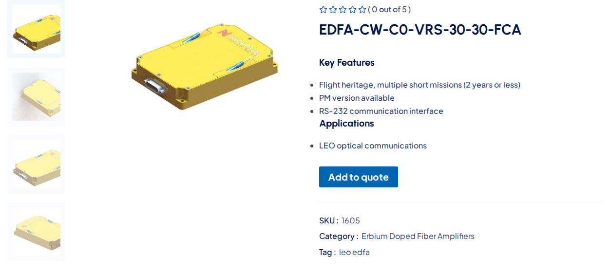
The EDFA-CW-C0-VRS-30-30-FCA is Nuphoton's primary space-qualified amplifier, designed specifically for vacuum operation in spacecraft and high-reliability environments.
| Parameter | Specification |
|---|---|
| Wavelength Range | 1540–1565 nm (C-band) |
| Gain | 30 dB nominal @ 0 dBm input |
| Output Power | +30 dBm nominal @ 0 dBm input |
| Input Power Range | -10 to +10 dBm |
| Vacuum Rating | ≤7.5×10⁻⁵ torr (by design) |
| Operating Temperature | – |
| Dimensions (L×W×H) | 120 × 80 × 20 mm |
| Power Consumption | ≤14 W @ +50 °C case temp, +30 dBm output |
| DC Power Input | +5 VDC ±5% |
| Telemetry Interface | RS-232 |
| Input/Output Fibre | SMF-28, 1 m typical |
| Connector | FC/APC |
Key electrical, optical, and mechanical specifications for the EDFA-CW-C0-VRS-30-30-FCA space-qualified amplifier. – see text: operating temperature lower bound.
The operating temperature lower bound for this model is given as −5 °C in the datasheet and as −10 °C on Nuphoton's product and services pages; the upper bound of +55 °C is consistent across both.
At 120×80×20 mm and ≤14 W power consumption, the module occupies a compact envelope relative to heritage space amplifiers, making it suitable for integration into spacecraft payload bays where volume and power budgets are constrained.
The RS-232 telemetry interface enables remote monitoring and control, with built-in input and output power monitoring across the full operating range — a practical feature for spacecraft housekeeping and fault detection without additional external circuitry.
Radiation Hardening and Product Tiers
Nuphoton's space-qualified EDFAs implement radiation-hardened fibre optics and control electronics to a total ionising dose (TID) tolerance of 100 krad, addressing programmes with stringent radiation requirements.
A separately available cost-effective C-band variant, tolerant to 5 krad TID, is positioned for New Space and LEO applications where radiation budgets are less demanding — giving procurement teams a tiered choice between heritage-grade and cost-optimised specifications within the same product family.
Nuphoton also offers a space-rated LEO EDFA providing over 40 dB of optical gain and 5 W of output power from a single vacuum-ready module, addressing mission profiles that require higher gain or greater output than the EDFA-CW-C0-VRS-30-30-FCA delivers.
Customisation and Procurement
Nuphoton's published capability extends to customising products for specific form, fit, and function requirements, with extended qualification available for programme-specific radiation testing and interface configurations — signalling that the company operates as an engineering partner rather than a catalogue-only supplier.
Nuphoton's AS9100 certification, flight-proven lunar mission heritage, and tiered TID product range — from 5 krad New Space variants to 100 krad heritage-grade units — reflect a product line calibrated to the breadth of the US NASA-ecosystem market, from cost-sensitive LEO constellations through to high-reliability GEO programmes.
Option 4
Polaris Photonics
Taiwan-based OCT amplifier specialist with a space-qualified range spanning booster EDFA, pre-amp EDFA, Er/Yb high-power, and SOA variants, including CubeSat-compatible form factors and SDA standards compliance.
Pros:
Multi-type amplifier range: booster, pre-amp, Er/Yb, SOA
CubeSat form factor with +5V supply compatibility
SDA ver 3.0 compliance for US constellation programmes
Er/Yb high-power option: up to 5 W CW
Cons:
SOA variant exhibits nonlinear effects under saturation
No documented in-orbit flight heritage on named missions
Polaris Photonics, based in Taiwan, has oriented its space-qualified product catalogue specifically around Optical Communication Terminal (OCT) integration, offering a range of amplifier modules that spans booster EDFAs, pre-amplifier EDFAs, an Er/Yb high-power variant, and a semiconductor optical amplifier.
Each module in the range passes a satellite environmental qualification test regime covering temperature, vibration, shock, thermal vacuum, and radiation testing, with qualification levels and duration following ISO 19683:2017 and ISO 15864:2004, and compliance with SDA ver 3.0.
Polaris Photonics Space Amplifier Specifications
The table below covers the four published amplifier variants across their core optical and mechanical parameters.
| Model | Type | Sat. Output Power | Gain | Noise Figure | Supply Voltage | Dimensions (mm) | Operating Temp. |
|---|---|---|---|---|---|---|---|
| EDFA-27-SP | Booster EDFA | 500 mW min. | 30 dB | 4.5 dB typ. | +12 VDC | 140 × 130 × 32 | -30°C to +65°C |
| EDFA-33-SP | Booster EDFA | 2.0 W min. | 40 dB | 4.5 dB typ. | +5 VDC / +3.3 VDC | 140 × 130 × 32 | -30°C to +65°C |
| EYDFA-37-SP | Er/Yb High-Power | 5 W CW (37 dBm) | 40 dB (35 dB with pre-amp) | 4.5 dB | 4 V, 25 A external | 140 × 130 × 32 | -30°C to +65°C |
| SOA-1550-SP | Semiconductor OA | 16 dBm typ. | 20 dB | 7 dB typ. | +5 VDC | 90 × 70 × 19.7 | -30°C to +65°C |
Key published specifications for the Polaris Photonics space-qualified amplifier range. – not publicly listed applies where a value does not appear in the datasheets.
The EDFA-33-SP is notable for its +5 VDC primary supply rail — directly compatible with standard CubeSat electrical power system buses — and its 140 × 130 × 32 mm footprint, which Polaris Photonics explicitly positions for CubeSat integration alongside OCT and free-space communication applications.
The EDFA-27-SP shares the same physical envelope and CubeSat application target, though it operates from a +12 VDC supply and delivers a saturated output of 500 mW across an operating wavelength of 1530–1560 nm.
The EYDFA-37-SP extends the range to 5 W CW output at 1540–1560 nm using Er/Yb double-clad fibre with multi-mode pumping and a two-stage amplification architecture; its large-core fibre technology is specifically noted as a means of suppressing Raman scattering, which can otherwise introduce nonlinear amplification at high power levels.
Optical gain exceeds 35 dB via the integrated EDFA pre-amplifier stage, accepting input signals as low as −20 dBm; Polaris Photonics lists free-space communications, OCT, and remote sensing among the stated applications for this module.
The space-qualified catalogue also lists the EDFA-PA-SP and EDFA-PA-LN-SP pre-amplifier EDFA variants for Rx-side applications.
The SOA-1550-SP provides wideband amplification from 1450 to 1600 nm with up to 20 dB gain and 16 dBm saturated output in a compact 90 × 70 × 19.7 mm form factor, operating from a +5 V supply.
ESA-commissioned research by Thales Alenia Space found that SOA technology generates unwanted frequency components through cross-gain saturation and Four-Wave Mixing processes under saturation conditions, making it less suited to multi-channel or high-linearity amplification scenarios; this is a characteristic of the SOA technology class rather than a product-specific finding.
Qualification Standards and SDA Compliance
Both the EDFA-27-SP and EDFA-33-SP datasheets cite qualification to ISO 19683:2017 and ISO 15864:2004 — the satellite component environmental test standards — alongside SDA ver 3.0 compliance, positioning these products for US Space Development Agency constellation procurement requirements.
The space-qualified components catalogue lists the LTR-1550-10-SP lightwave transceiver module with SDA 4.0.0 compliance.
Polarisation-maintaining versions of the EDFA-27-SP and EYDFA-37-SP are available on request, an option relevant to coherent link architectures where polarisation control at the amplifier output is required.
Custom EDFAs Built for Your Application
We design and build tailored EDFAs for free-space optical communications and beyond. If your programme has specific power, form factor, or wavelength requirements, our team can help.

Option 5
GIP Technology
Taiwan-based photonics specialist founded in 1999, with satellite flight heritage through the TASA Triton programme and a C-band space-qualified EDFA gain block using radiation-hardened erbium-doped fibre.
Pros:
Satellite flight heritage via TASA Triton (2023)
Radiation-hardened Er-doped and Er/Yb fibre gain medium
2018 LEO radiation, thermal vacuum, vibration verified
ISO 9001:2015 certified quality system
Cons:
Space heritage centred on FOG, not lasercom
Triton heritage covers light source, not EDFA module
Fewer published space-lasercom qualification data points
Company Background
GIP Technology Corporation was established in October 1999 in Taipei, Taiwan, and has since built a product portfolio spanning fibre amplifiers, fibre lasers, and broadband light sources across telecommunications, industrial, and aerospace markets.
The company holds ISO 9001:2015 certification and, per its published quality page, designs and manufactures to Telcordia/ITU standards as well as military and space standards.
AER-SCEFA-00-00-M Gain Block Module
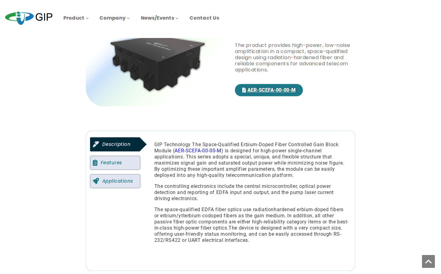
The AER-SCEFA-00-00-M is GIP's Space-Qualified Erbium-Doped Fibre Controlled Gain Block Module, operating in the C-band and designed for high-power, low-noise single-channel amplification in a compact, space-qualified form factor.
The module's gain medium uses radiation-hardened erbium-doped fibres or erbium/ytterbium co-doped fibres, with all other passive fibre optic components specified as either high-reliability category items or best-in-class high-power fibre optics. GIP states a maximum saturated output power of up to 36 dBm.
Controlling electronics include a central microcontroller, optical power detection and reporting at both input and output, and pump laser current driving circuitry. Interface access is via RS-232, RS-422, or UART.
- Target applications: Optical ground stations, optical inter-satellite links, and free-space optical (FSO) communications — the full lasercom link stack.
- Gain medium: Radiation-hardened erbium-doped fibre or erbium/ytterbium co-doped fibre, with all passive components specified as high-reliability or best-in-class high-power fibre optics.
- Output power: Maximum saturated output power up to 36 dBm, per GIP Technology's published product page.
- Interfaces: RS-232, RS-422, and UART electrical interfaces with user-friendly status monitoring.
GIP also offers the AER-SCASE-00-00-M, a space-qualified ASE (Amplified Spontaneous Emission) light source module aimed at fibre optical gyroscope and sensor applications — extending GIP's aerospace product breadth across both communications amplification and navigation-grade sensing on the same spacecraft bus.
GIP Technology Qualification and Flight Heritage
GIP's space-environment qualification evidence spans two distinct milestones. In December 2018, the company passed LEO radiation, thermal vacuum, and 25 GHz vibration space verification tests for its BLS (broadband light source) module, developed for satellite fibre optical gyroscope applications.
The more significant milestone came in October 2023, when the TASA (Taiwan Space Agency) Triton satellite was successfully launched and began operations. GIP had been a key partner in the Triton programme since 2013, supplying a radiation-hardened fibre light source — specifically a four-port rad-hard fibre light source — as a critical component of the spacecraft's space-grade fibre optical gyroscope. GIP states that it passed all rigorous space environment tests for this programme.
The product that flew on the TASA Triton satellite was GIP's radiation-hardened fibre light source for a space-grade FOG — not the AER-SCEFA-00-00-M EDFA gain block module. The Triton mission validates GIP's space-environment competence and its radiation-hardened fibre technology, but it is not direct flight heritage for the EDFA gain block specifically.
This distinction matters for procurement teams evaluating lasercom-specific heritage. GIP's documented in-orbit experience is rooted in FOG and navigation-system components; the EDFA gain block module extends that space-proven fibre technology into communications amplification, but carries a narrower lasercom-specific heritage base than some other entries in this comparison.
Fewer published space-lasercom-specific qualification data points are publicly available for the AER-SCEFA-00-00-M than for some other entries on this list. That reflects the scope of what GIP has publicly documented to date, not necessarily the limits of its qualification activity.
Conclusion
Choosing the right space optical amplifier for your programme
The first filter is always the amplifier's role in the optical link: Er/Yb for transmitter boost, low-noise EDFA for receiver pre-amplification — that choice precedes SWaP, heritage, or supplier shortlisting.
From there, the decision narrows through hard constraints: physical envelope and power budget, programme standards compliance, and how deeply a supplier's radiation heritage is built into the manufacturing chain rather than bolted on.
TRL level and qualification documentation are the final gate — and closing them means a direct conversation with the supplier around your specific mission profile.
Frequently asked questions about space qualified optical amplifiers
This section addresses the terminology, standards, and technology questions that commonly arise when evaluating space optical amplifier hardware for a spacecraft programme. Each answer stands on its own and can be read independently of the main comparison.
Space grade refers to components built from materials and processes suitable for the space environment. Space qualified means the assembled amplifier has undergone a formal qualification test campaign — covering radiation TID and displacement damage testing, thermal vacuum cycling, and vibration and shock — with documented test results showing it passed. The distinction matters enormously in procurement. A space-grade component does not guarantee system-level qualification: the assembled unit may still fail under the combined stresses of launch and the in-orbit environment. A programme that specifies "space grade" rather than "space qualified" is accepting a fundamentally different risk profile, because it has no documented evidence that the complete amplifier system has been tested and proven to survive those conditions.
The two primary frameworks are ESCC (European Space Components Coordination), used in ESA programmes, and US MIL-STD / MIL-PRF standards, used in US defence and government programmes. ESCC qualification, administered through ESA and the ESCIES system, involves a structured evaluation and qualification testing phase, with approved components listed on the ESCC Qualified Parts List. TRL (Technology Readiness Level) is the cross-agency maturity scale used as a common language across programmes: per the ESA ISO 16290-based framework, TRL 8 is an actual system completed and accepted for flight ("flight qualified"), and TRL 9 is an actual system "flight proven" through successful mission operations. Programmes should specify which framework applies and at what TRL they require hardware to be delivered, because a supplier's qualification documentation under one framework may not map cleanly to another.
EDFAs (erbium-doped fibre amplifiers) are the established technology for space laser communications because of their gain, output power, bandwidth, and stability at C-band wavelengths around 1550 nm. An ESA-commissioned trade-off study conducted by Thales Alenia Space concluded that EDFAs are clearly the best option for space applications across these performance axes. The alternative technologies each carry specific limitations. SOAs (semiconductor optical amplifiers) do not provide fully linear amplification: cross-gain saturation and four-wave mixing generate unwanted frequency components, making them poorly suited to multi-channel or high-linearity applications. EDWAs (erbium-doped waveguide amplifiers) showed sensitivity to gamma radiation in testing, with the same ESA study finding that gamma radiation is a clear issue for that technology. For EDFAs, radiation-hardened doped fibre is the critical enabling component: gain degradation under total ionising dose is the primary failure mode, and the type of fibre used determines how severely gamma radiation affects performance.
TID (total ionising dose) requirements vary significantly by orbit and mission duration. According to NASA NEPP radiation environment data, LEO missions accumulate in the range of approximately 5–10 krad (assuming a 7-year mission with typical spacecraft shielding), while GEO missions can reach around 50 krad over a comparable period; higher-shielded or longer missions will shift these figures. Programmes with GEO assets and 15-year lifetimes should plan for requirements well above those baseline figures. The right TID specification for a given programme is derived from a radiation environment model — tools such as ESA's SPENVIS are the standard approach — applied to the specific orbit, shielding configuration, and mission duration. Suppliers covered on this page offer products rated across a range from cost-optimised New Space variants to full rad-hard specifications; Lumibird's Keopsys range, for example, publishes TID ratings from 10 krad to 100 krad depending on the model. Selecting the appropriate product starts with defining the mission TID requirement, not defaulting to the highest-rated option available.
Yes. Several suppliers covered on this page offer modules compatible with CubeSat form factors. Polaris Photonics lists CubeSat as a named application for its EDFA-33-SP, which operates from a single +5V DC supply and measures 140 × 130 × 32 mm — a compact footprint suited to constrained payload volumes. That module is also designed to the SDA (Space Development Agency) ver 3.0 standard, which is increasingly relevant for US government small satellite and CubeSat programmes. Lumibird's Keopsys subsidiary similarly states that modules compatible with the CubeSat form factor can be proposed for constellation projects. The key integration constraints to assess for any CubeSat application are power supply voltage, physical dimensions relative to the available payload volume, and mass budget. Qualification test levels for CubeSat-targeted modules may also differ from those applied to full spacecraft hardware, so programmes should confirm the specific test campaign against their mission requirements.
Mission heritage — documented use of a supplier's hardware in actual space missions — is evidence that the hardware has survived launch loads and the in-orbit environment, not just ground-based qualification testing. It does not guarantee suitability for a different mission profile: a different orbit, a higher TID level, or a different link scenario may impose conditions the heritage mission did not. Nevertheless, it substantially reduces procurement risk compared to hardware that has only been ground-tested. Suppliers with TRL 9 components carry the strongest heritage signal, because per the ESA framework, TRL 9 means the actual system is "flight proven" through successful mission operations — not merely qualified, but operated in space. When evaluating heritage claims, programmes should ask two questions: does the heritage cover the specific product being procured, rather than a related component from the same manufacturer, and was the heritage mission environment comparable to their own in terms of orbit, radiation exposure, and operational profile?