

Introduction
If you are working on a satellite optical communications programme, you already know that finding an amplifier is not the hard part — finding the right one is.
The selection challenge is genuinely complex, because the decisions involved do not sit neatly in sequence: the technology choice shapes the qualification approach, the qualification approach constrains the vendor pool, and the vendor pool feeds back into what is technically achievable within your mission constraints.
This guide is written for engineers, systems architects, and procurement professionals who need a coherent framework for navigating those decisions — not a datasheet aggregation, and not an abstract photonics tutorial.
Every parameter discussed here is grounded in what it means for a real mission trade-off, from technology selection through to vendor evaluation.
TL;DR
Choosing a space-qualified optical amplifier is a systems-level decision, not a specification-matching exercise. Mission context, qualification strategy, and supplier heritage all interact — and getting any one of them wrong has consequences that ripple across the others. The framework in this guide helps you navigate all three with clarity.
This article covers:

Amplifier technology types: EDFA vs SOA mission fit
What space qualification actually entails
Key performance parameters in mission context
COTS vs fully space-qualified trade-offs
Integration by platform: CubeSat, LEO, GEO
How to evaluate space-heritage vendors
What is a Space Qualified Optical Amplifier?
A telecom-grade EDFA and a space qualified optical amplifier can look nearly identical on a bench — same fibre pigtails, same rack-mount form factor, similar optical specifications. The engineering gap between them, however, is not incremental. It is the difference between hardware designed for a controlled data-centre environment and hardware designed to survive launch loads, hard vacuum, ionising radiation, and thermal swings that no terrestrial installation ever encounters.
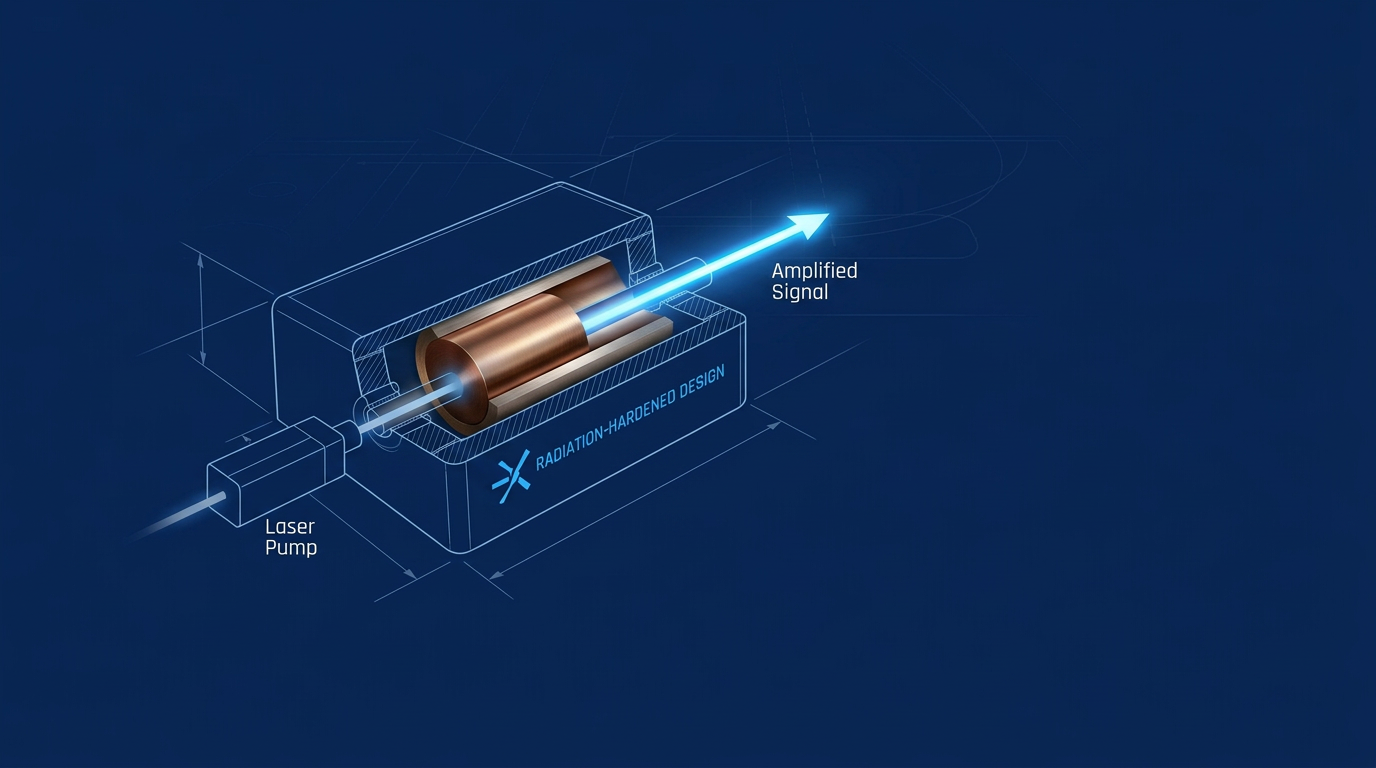
A space-qualified optical amplifier is an optical amplifier — a device that boosts the power of an optical signal without converting it to an electrical form — that has been specifically engineered and tested to operate reliably throughout the harsh conditions of a space environment.
The space environment imposes four categories of stress that have no direct terrestrial analogue: radiation (both accumulated total ionising dose and transient single-event effects), thermal extremes and cycling across ranges far wider than any ground-based installation, vacuum with strict outgassing constraints, and the intense vibration and shock of launch.
The "space-qualified" designation is not a marketing label. It implies a documented engineering programme: materials selected for vacuum compatibility, components screened against radiation susceptibility, assemblies tested to launch-profile mechanical loads, and thermal performance verified across the full operational range — all supported by traceable test data.
This is precisely why an engineer cannot take a high-quality terrestrial or telecom-grade COTS amplifier and integrate it directly into a spacecraft. The doped fibres, pump laser diodes, and control electronics inside a standard EDFA are not designed to tolerate accumulated radiation dose; their performance degrades — and in some cases fails — under the ionising environment of low Earth orbit or beyond.
Beyond radiation, terrestrial amplifiers use adhesives and coatings that can outgas in vacuum, depositing contamination onto optical surfaces and degrading performance over a mission lifetime. They have not been subjected to launch-profile shock and vibration testing, and their thermal designs assume convective cooling that simply does not exist in orbit.
The primary application driving demand for this class of hardware is free-space optical communications (FSOC) — optical data links that propagate through open space rather than through fibre. FSOC links between satellites (inter-satellite links, or ISLs) and between satellites and ground stations require high-power, low-noise optical amplification that RF systems cannot match at comparable data rates and spectral efficiency.
As noted in SPIE proceedings on high-efficiency fibre optic amplifiers for new-space constellation applications, space-grade fibre optic amplifiers are required in large numbers to enable FSO links for the many planned LEO satellite constellations — with requirements spanning low noise figure, high gain, high output power, high wall-plug efficiency, and radiation tolerance.
NASA's Lunar Laser Communication Demonstration (LLCD), launched in 2013, demonstrated laser communications from lunar orbit at 622 Mbps — achieving 50% less mass and 25% less power than a comparable RF system. NASA's Laser Communications Relay Demonstration (LCRD), launched in December 2021 and operating in geosynchronous orbit, transmits data over laser links at 1.2 Gbps and has conducted over 2,600 experiment configurations with its two ground stations.
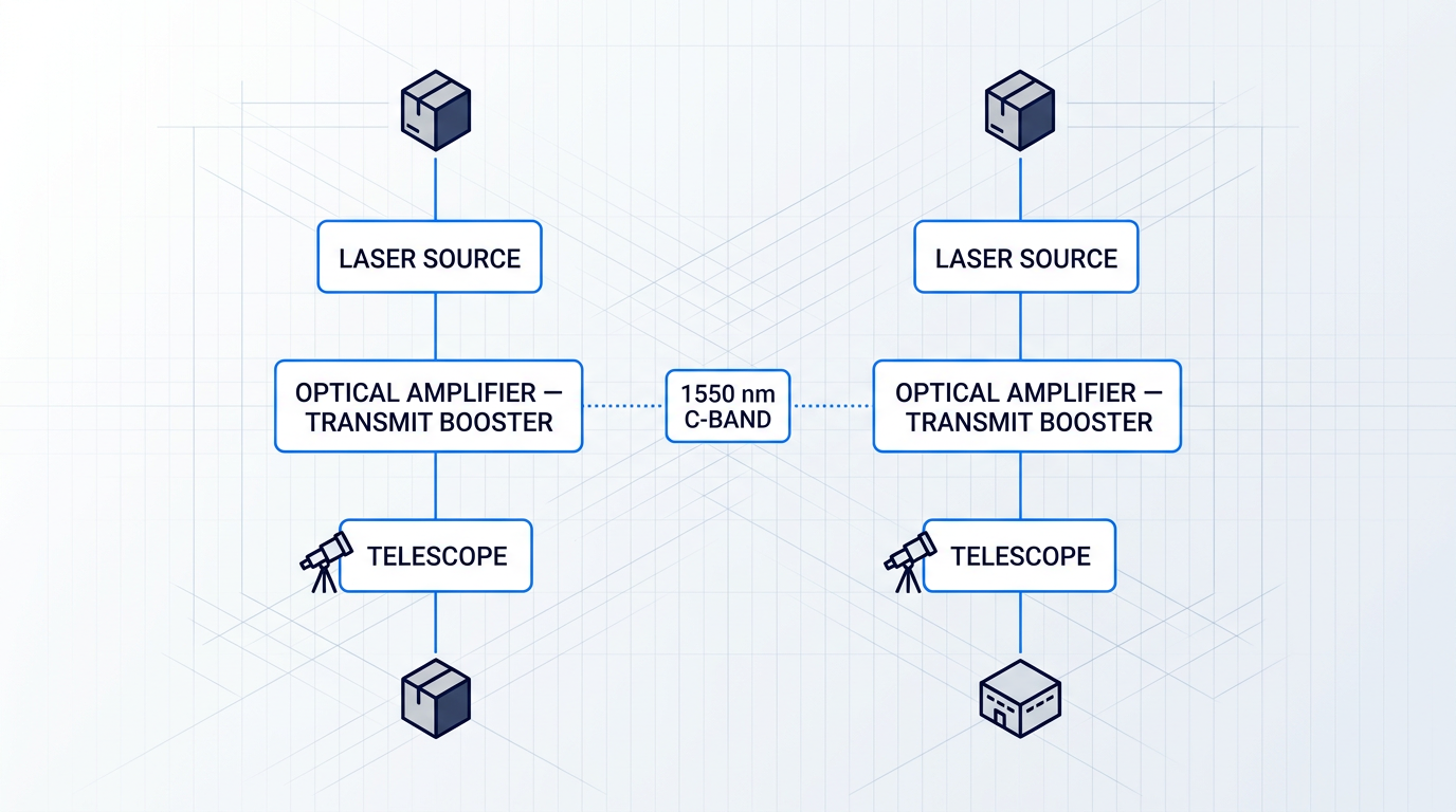
Both NASA programmes operate at or near 1550 nm — a wavelength that sits in the C-band (approximately 1530–1565 nm) and has been adopted as the standard for space laser communications. NASA documentation confirms that the 1550 nm wavelength allows direct leveraging of terrestrial fibre telecom components, which is a significant cost and maturity advantage for space system developers.
Two amplifier families dominate the space-qualified optical amplifier landscape. Erbium-doped fibre amplifiers (EDFAs) use a short length of silica fibre doped with erbium ions as the gain medium, operating in the C-band from approximately 1530 to 1565 nm. Semiconductor optical amplifiers (SOAs) use an electrically pumped semiconductor gain medium, offering broader wavelength coverage across multiple bands and compact form factors compatible with photonic integrated circuit fabrication.
The 1550 nm C-band is where two independent structural forces converge: it is the lowest-attenuation window of silica glass — the property that made EDFAs the backbone of terrestrial long-haul telecommunications — and it is the wavelength standard adopted by NASA and the broader space laser communications community for FSOC programmes.
The C-band around 1550 nm is not an arbitrary choice for FSOC. It is the point where silica fibre's lowest-attenuation window, decades of mature telecom component development, and NASA's operational laser communications programmes all align — giving EDFAs a structural advantage in most current FSOC applications that goes beyond raw optical performance.
With that foundation established, the guide moves into the technology-selection question: how EDFAs and SOAs compare across operating principles, mission-fit strengths, and the specific trade-offs that determine the right amplifier architecture for a given mission.
EDFA vs SOA: Matching Amplifier Technology to Your Mission
Choosing between an erbium-doped fibre amplifier (EDFA) and a semiconductor optical amplifier (SOA) is not a question of which technology is better — it is a question of which technology fits the mission you are building. The two amplifier families have genuinely different performance envelopes, and the right answer depends on your wavelength, required output power, noise budget, and integration constraints.
EDFA: Operating Principle and Mission-Fit Strengths
An EDFA amplifies optical signals by passing them through a length of silica fibre whose core is doped with trivalent erbium ions (Er³⁺), excited by a pump laser operating at either 980 nm or 1480 nm. The pump establishes population inversion in the erbium ions; signal photons in the C-band (1530–1565 nm) or L-band (1565–1625 nm) then stimulate coherent emission, producing gain entirely in the optical domain without any electrical conversion.
The engineering outputs of this mechanism are well-characterised: small-signal gains of 20–40 dB, noise figures that approach the 3 dB quantum limit in well-designed devices (practical values typically 4–6 dB), and saturation output powers of 20 dBm or more in booster configurations.
These characteristics map directly to two critical mission roles. In a preamplifier role — amplifying a weak received signal before detection — the EDFA's low noise figure is decisive: degrading the optical signal-to-noise ratio as little as possible at the receiver front end directly determines link margin. In a booster role — amplifying the transmitter output before launch into the free-space link — the EDFA's high gain and saturation output power are the relevant axes.
Two further characteristics matter for high-data-rate FSOC links. Polarisation-maintaining (PM) fibre variants preserve the polarisation state required by coherent modulation formats such as DPSK and QPSK — both of which NASA's LCRD terminals employ at 1550 nm. The long upper-state lifetime of erbium ions (several milliseconds) also suppresses inter-channel gain crosstalk in WDM configurations, since the gain medium cannot respond to intensity fluctuations at inter-channel frequencies.
SOA: Operating Principle, Strengths, and Trade-offs
An SOA achieves gain through current injection into a semiconductor gain medium — structurally similar to a laser diode, but with antireflection-coated or angled facets that suppress cavity feedback and allow single-pass amplification. The wavelength of operation is set by the active-layer material composition, giving SOAs coverage across the O, S, C, and L bands without being locked to a fixed gain spectrum.
The practical advantages follow from the electrical pumping architecture: no separate pump laser diodes are required, the device is compact (sub-millimetre gain medium length versus metres of doped fibre), and the SOA is compatible with photonic integrated circuit (PIC) fabrication, enabling on-chip integration pathways that are structurally unavailable to fibre-based EDFAs. The carrier lifetime in an SOA is on the order of 500 ps to 5 ns — orders of magnitude shorter than the erbium upper-state lifetime — which gives SOAs fast gain dynamics useful in switching and all-optical signal processing applications.
The trade-offs are real and mission-relevant. SOA noise figures are typically 6–10 dB, substantially higher than a well-optimised EDFA, which limits SOA utility in low-noise preamplifier roles where every fraction of a decibel in noise figure translates directly to link margin. Gain saturation occurs at relatively low optical power — typical saturation output powers in standard telecom SOA modules are around 10 dBm — which constrains high-power booster applications.
Polarisation-dependent gain (PDG) is a further complication: TE and TM polarisation modes experience different confinement factors in a planar semiconductor waveguide, producing gain differences of up to 5–8 dB in standard designs. Strained quantum-well structures can reduce PDG substantially, but this requires deliberate design effort. For coherent modulation formats where polarisation state must be preserved, this is a non-trivial engineering constraint.
The short carrier lifetime that enables fast gain dynamics also creates susceptibility to high-frequency noise: a carrier lifetime of around 1 ns means the SOA gain can respond to noise or fluctuations at frequencies up to approximately 1 GHz, introducing potential signal degradation in high-data-rate links. These are engineering trade-offs, not disqualifying flaws — the SOA has legitimate roles where these limitations are not the binding constraint.
The table below compares EDFA and SOA across the mission-relevant axes that drive technology selection decisions.
| Parameter | EDFA | SOA |
|---|---|---|
| Small-signal gain range | 20–40 dB | 10–30 dB (up to ~28 dB internal gain in III-V/silicon hybrid designs) |
| Noise figure | 4–6 dB (practical); 3 dB quantum limit | 6–10 dB (standard designs); ~5.4 dB demonstrated in watt-class tapered designs |
| Saturation output power | ≥20 dBm in booster configurations; higher in multi-stage amplifier chains | ~10 dBm in standard telecom modules; up to +30 dBm (1.2 W) in advanced tapered-chip designs |
| Pump mechanism | Optical (980 nm or 1480 nm laser diode) | Electrical (direct current injection) |
| Wavelength coverage | C-band (1530–1565 nm); L-band (1565–1625 nm) | O, S, C, L bands — set by active-layer material composition |
| Polarisation sensitivity | Polarisation-insensitive (standard); PM fibre variants available for coherent formats | PDG up to 5–8 dB in standard designs; reduced with strained quantum-well structures |
| Integration form factor | Fibre-based module (cm to metre-scale active medium) | Chip-scale; PIC-compatible; sub-mm gain medium |
| Primary mission roles | High-power FSOC booster; low-noise receiver preamplifier; WDM multi-channel amplification | Compact FSOC stages; PIC-integrated signal processing; wavelength-flexible applications outside C-band |
Side-by-side comparison of EDFA and SOA across key mission-relevant performance and integration axes to support amplifier technology selection.
Reading across the table, the axes that matter most depend entirely on mission profile. For a high-power FSOC transmitter booster at 1550 nm, the saturation output power row is the decision axis — EDFA booster configurations deliver 20 dBm or more, and multi-stage architectures extend this considerably further, while standard SOA modules saturate around 10 dBm. For a receiver preamplifier, the noise figure row dominates: the 4–6 dB EDFA advantage over a typical SOA translates directly to link margin and, ultimately, to the aperture or transmit power required at the other end of the link.
Where the SOA column becomes competitive is in the integration form factor and wavelength coverage rows. Missions that require chip-scale integration, that are building towards PIC-based optical payloads, or that operate at wavelengths outside the EDFA gain band — for instance, quantum key distribution systems at 850 nm or sensing applications in the O-band — will find the SOA's material flexibility to be a structural advantage rather than a consolation.
If your mission requires high output power or low-noise preamplification at 1550 nm C-band, the EDFA's performance envelope fits. If your mission prioritises chip-scale integration, PIC compatibility, or operation at wavelengths outside the EDFA gain band, the SOA's architecture is the right starting point — accepting its noise figure and saturation power limitations as known constraints.
The 1550 nm Wavelength Ecosystem Argument
The EDFA's alignment with the 1550 nm C-band is not simply a specification advantage — it reflects a convergence of the component supply chain, qualification heritage, and link budget assumptions that have accumulated around this wavelength over decades. The C-band coincides with the lowest-attenuation window of silica glass, and it is the wavelength at which the commercial fibre communications industry has made its deepest investment in components, testing, and reliability data.
For space FSOC specifically, this convergence is traceable and concrete. NASA's Laser Communications Relay Demonstration (LCRD) operates at 1550 nm, with each flight terminal using a telecommunications laser diode master oscillator seeding an erbium-doped fibre power amplifier — a MOPA architecture supporting DPSK and PPM modulation at a coded user rate of 1.244 Gbps. The Lunar Laser Communications Demonstration (LLCD) used a 0.5 W laser at 1550 nm. NASA's Deep Space Optical Communications (DSOC) project similarly targets the ~1550 nm downlink band. The 1550 nm wavelength is where flight-proven architectures, available COTS components, and upscreening programmes have converged — a programme selecting a different wavelength takes on the burden of building that heritage from scratch.
Emerging Consideration: High-Power SOAs for FSOC
The performance gap between EDFAs and SOAs in high-power booster roles is narrowing, and this is an area worth tracking. SPIE proceedings have documented a tapered-chip SOA delivering more than 30 dBm (1.2 W) of continuous-wave output power at 1550 nm in a single-mode fibre-coupled package — described as a world record for this configuration at the time of publication, achieved with approximately 16 dB of gain and a noise figure calculated at 5.4 dB.
Separately, researchers from Space Dynamics Laboratory presented results at SPIE Photonics West 2025 evaluating a 1 W PIC SOA for FSO communication applications, demonstrating successful transmission of BPSK at up to 50 Gbps and QPSK at up to 100 Gbps, with constellation error-vector magnitude values described as comparable to an off-the-shelf EDFA. The authors identified electro-optical conversion efficiency, output power, and beam quality as parameters of importance and outlined a path forward for FSO suitability.
These demonstrations are encouraging, but they represent research-level results rather than qualified space hardware. The remaining engineering challenges — including space environmental qualification of the SOA gain medium, long-term reliability under radiation exposure, and achieving the full performance envelope in a flight-ready package — have not yet been addressed in published form for these watt-class SOA designs. This is an active research direction, not a settled capability, and programme teams should monitor it without treating it as a near-term drop-in alternative to flight-qualified EDFAs.
Understanding which amplifier technology fits your mission is a necessary first step — but technology selection only sets the starting point. Whichever architecture you choose, it must then survive the space environment: radiation, thermal cycling, vibration, and vacuum, each of which interacts differently with erbium-doped fibre and semiconductor gain media. That is the focus of the next section.
What Space Qualification Actually Means for Optical Amplifiers
Space qualification is not a certificate you obtain at the end of a programme — it is a systematic engineering discipline that must be woven into the design from the earliest phases.
For a space qualified optical amplifier, qualification means demonstrating through analysis, environmental testing, and controlled documentation that the hardware will survive and perform across its full mission lifetime, under conditions it can never be entirely shielded from.
Getting this wrong — or treating it as a late-stage compliance exercise — is one of the most expensive mistakes a satellite programme can make, because rework after Critical Design Review costs orders of magnitude more than margin designed in from the start.
The environmental test regime for a space optical amplifier covers four distinct threat categories: thermal cycling, vibration and shock, vacuum operation, and radiation.
Each category encodes real failure modes observed in flight hardware; the test levels are not arbitrary margins but engineering judgements about what the component must survive with confidence.
Environmental Test Regimes for Optical Amplifiers
Thermal cycling tests the amplifier's ability to survive repeated excursions between temperature extremes, with qualification levels exceeding the operational range by a defined margin — typically ±10°C beyond the allowable flight temperature range under GSFC-STD-7000B (GEVS), and ±10°C under MIL-STD-1540E.
Cycle counts are not based on expected mission thermal excursions; they are designed to induce a prescribed level of cumulative stress. For optoelectronics and longer-duration missions, NASA practice specifies 100 or more cycles; assemblies at lower risk levels may use 30–60 cycles.
Vacuum removes convective cooling entirely, so the amplifier's thermal management must rely on conductive and radiative paths alone — a constraint that must be validated under vacuum conditions, not just at ambient pressure.
Vibration and shock testing is performed to launcher-specific profiles, not generic spectra. The random vibration profile is derived from the launch vehicle user manual for the specific mission; qualification levels typically add a margin of +3 dB over the maximum expected environment per ECSS-E-ST-10-03.
For fibre assemblies within an optical amplifier, vibration is particularly demanding: adhesive bonds, fibre routing, and connector interfaces are all susceptible to fatigue and delamination under sustained random excitation.
Shock events — fairing separation, pyrotechnic deployments — impose impulsive loads that must also be demonstrated at qualification levels, applied in all three orthogonal axes.
Vacuum operation is fundamental to space hardware, but outgassing introduces a specific risk for optical amplifiers: polymeric coatings, buffer materials, and adhesives used in fibre assemblies can release volatile species that contaminate optical surfaces and degrade transmission.
The standard screening test is ASTM-E595, performed at 125°C for 24 hours. The ECSS standard ECSS-Q-ST-70-02C specifies a test pressure of 10⁻⁴ Pa; NASA documentation references an equivalent condition of 10⁻⁶ Torr — both represent high-vacuum screening conditions.
Acceptance criteria are Total Mass Loss (TML) below 1% and Collected Volatile Condensable Materials (CVCM) below 0.1%.
For optical amplifiers, where outgassed species could deposit on gain fibre end-faces or pump coupling optics, ECSS-Q-ST-70-02C notes that more stringent limits may apply — and configuration-level testing, not just materials-level screening, is often required.
Radiation Effects on Optical Amplifiers
Radiation is the most mission-specific and technically demanding aspect of space qualification for optical amplifiers. Three distinct mechanisms affect different parts of the amplifier, each requiring a different test and mitigation strategy.
- Total Ionising Dose (TID): Cumulative ionising damage from trapped electrons and protons. Degrades active electronics and causes attenuation in doped gain fibres. The dominant concern for long-lifetime missions.
- Displacement Damage / TNID: Non-ionising energy deposition displaces atoms in semiconductor crystal lattices. Critically affects pump laser diodes, reducing efficiency and increasing threshold current over mission lifetime.
- Single Event Effects (SEE): A single energetic particle traverses a sensitive node in control electronics, causing transient upsets or permanent damage. Relevant to the amplifier's drive and monitoring circuitry.
The total radiation dose an amplifier accumulates depends strongly on orbit class. LEO missions typically see 5–10 krad TID over a 7-year mission, with the South Atlantic Anomaly (SAA) as the dominant contributor.
MEO environments are the harshest, with TID ranging from 10–100 krad as the spacecraft passes through the Van Allen belts. GEO missions accumulate approximately 50 krad, driven primarily by cosmic rays above the trapped radiation belts.
These are indicative figures based on typical spacecraft shielding; mission-specific analysis using tools such as SPENVIS or SHIELDOSE-2 is always required before selecting components or specifying shielding.
| Orbit Class | Indicative TID (7-year mission) | Dominant Radiation Source |
|---|---|---|
| LEO | ~5–10 krad | Trapped protons/electrons; South Atlantic Anomaly passes |
| MEO | ~10–100 krad | Van Allen belts (inner and outer); harshest trapped particle environment |
| GEO | ~50 krad | Cosmic rays and solar particles; above trapped radiation belts |
Comparison of indicative TID ranges and dominant radiation sources by orbit class, to ground component selection and shielding decisions in mission context.
The spread across orbit classes directly drives component selection and shielding strategy. A pump laser diode adequate for a LEO smallsat mission may fail well before end-of-life in a MEO navigation platform, where displacement damage accumulation is an order of magnitude higher.
Shielding can reduce TID for low-energy particles, but adds mass and has diminishing returns beyond a few millimetres of aluminium — making component-level radiation tolerance the primary mitigation for most missions.
Radiation-induced attenuation (RIA) in erbium-doped and erbium-ytterbium co-doped gain fibres is a failure mechanism specific to optical amplifiers. Ionising radiation creates colour centres (point defects) in the doped glass matrix that absorb at both pump and signal wavelengths, progressively reducing the amplifier's gain and output power over the mission lifetime.
The effect is described at the amplifier level as radiation-induced gain variation (RIGV). Some recovery occurs when the radiation source is removed, but a residual permanent attenuation remains — and the net effect at end-of-life depends on fibre composition, dose rate, temperature, and operating wavelength.
The practical implication is that end-of-life (EOL) power margin must be designed into the amplifier architecture from the outset, not added retrospectively.
Fibre composition optimisation is the primary radiation-hardening lever at the gain medium level. Cerium (Ce) co-doping via the Ce³⁺/Ce⁴⁺ redox mechanism is a confirmed effective strategy, acting to limit defect formation and stabilise lasing properties under ionising radiation.
Aluminium co-doping — widely used in commercial EDFAs to broaden and flatten gain — is known to be a precursor to radiation-induced structural defects and increases RIA. This is a significant consideration when selecting gain fibre for space applications, where the commercial optimum and the radiation-hard optimum diverge.
Radiation-induced gain degradation accumulates continuously over the mission lifetime. End-of-life power margin must be sized and designed into the amplifier architecture at the start of the programme — it cannot be added after the optical design is frozen.
Standards Frameworks: ECSS, ESCC, and NASA
ECSS-Q-ST-60-15C Rev.1 (March 2025) is the primary standard governing Radiation Hardness Assurance (RHA) for ESA programmes.
RHA is not a single test — it is a project-specific programme that begins at mission concept, defines the radiation environment per ECSS-E-ST-10-04, assesses component sensitivity against TID, TNID, and SEE, performs worst-case analysis of radiation-induced parameter drift, and documents results in a formal Radiation Analysis Report.
The standard requires that no TID effect cause permanent damage or degrade performance outside specification limits during the radiation design lifetime — a requirement that must be demonstrated by test data, not assumed.
ECSS-Q-ST-70C governs materials, mechanical parts, and processes, requiring that all organic materials be evaluated for outgassing characteristics and that materials exposed to radiation be assessed for resistance to the expected mission dose.
ECSS-Q-TM-70-51A addresses fibre optic harness manufacturing for spacecraft and is directly relevant to the fibre assemblies within optical amplifiers. It requires that adhesives demonstrate compatibility with mission requirements including outgassing rate and radiation resistance — encoding the failure modes that have destroyed flight hardware in previous programmes.
The ESCC (European Space Components Coordination) qualification system provides component-level qualification schemes recognised across all ESA missions. Components on the ESCC Qualified Parts List (QPL) have been evaluated and qualified to defined specifications, with manufacturer supply chains audited by the ESCC Executive.
For projects complying with ECSS-Q-ST-60C, ESCC-qualified products are in most cases pre-approved, reducing the engineering and test burden on the programme. The ESCC system is the mechanism by which individual EEE components — including the active electronics within an optical amplifier — achieve qualified status for ESA missions.
NASA's approach to photonic component qualification follows a modified EEE (Electrical, Electronic, and Electromechanical) parts methodology, adapted for the additional requirements of optoelectronic components: wavelength stability, output power, beam profile, and fibre coupling.
A critical principle is lot-level qualification: flight parts are selected from the specific production lot that was qualified, not from a different lot produced by the same process.
As documented in the 2024 NEPP ETW presentation from NASA Goddard's Photonics group, even previously Telcordia-qualified components must undergo lot-level flight screening and qualification testing — because Telcordia qualification applies to the manufacturer's process, not the specific procured lot.
Functional and environmental testing — vibration, thermal-vacuum, radiation — must be performed on the actual flight lot, with testing parameters customised to the intended use conditions and exact part type.
Qualification vs Acceptance Testing
Qualification testing demonstrates that the design has adequate margins under conditions more severe than the expected mission environment.
It is performed once — or once per significant design iteration — on dedicated qualification units produced to the same drawings, materials, and processes as flight hardware. Qualification test levels exceed the maximum predicted environment by a defined margin: for thermal, typically ±10°C beyond the allowable flight temperature range; for vibration, +3 dB over the maximum expected spectrum.
The purpose is to prove that the design, not the individual unit, can survive — which is why qualification testing need not be repeated for each flight unit, provided the design and manufacturing process remain unchanged.
Acceptance testing is performed on every flight unit delivered. Its purpose is narrower: to verify that each individual unit is free from workmanship defects and meets the qualified design.
Acceptance test levels do not exceed the maximum predicted mission environment — they are not designed to demonstrate margin, but to screen out manufacturing anomalies. Per ECSS-E-ST-10-03, acceptance tests must not create conditions that exceed safety margins or cause unrealistic failure modes.
Conflating these two test types is a common and costly error. Over-testing flight units to qualification levels can consume life margin and induce fatigue that reduces on-orbit reliability; under-testing leaves workmanship defects undetected until on-orbit failure.
With the qualification framework, radiation physics, and test vocabulary now established, the next question is how to translate this understanding into performance specifications that will still be met at end-of-life — covering output power, noise figure, and SWaP in the context of the degradation mechanisms introduced here.
Key Amplifier Parameters in Mission Context
A datasheet can tell you that an amplifier delivers 33 dBm output power with a 4.5 dB noise figure — but neither number tells you whether that amplifier is the right choice for your mission. The parameters that define a space qualified optical amplifier only become meaningful when they are mapped against what your link actually requires, what your platform can physically accommodate, and what the hardware must still deliver at end of life.
Output Power and the Link Budget
The starting point for any output power specification is not a product catalogue — it is your optical link budget, worked backwards from the required received signal power at the far end of the link.
For LEO constellation FSOC applications, saturated output power in the 1–10 W class is the current working range, with the SPIE proceedings on high-efficiency amplifiers for new-space constellations confirming requirements of 1 W to 10 W or more for booster amplifiers in this class.
Deep-space links impose a fundamentally different demand: the JPL Descanso monograph series documents that current laser transmitters for deep-space missions are only around 10% efficient, and that peak powers on the order of kilowatts are required for adequate link margin at interplanetary ranges — a regime where fibre amplifiers are among the few candidates capable of delivering the required peak power in narrow pulses.
The amplifier's role within the transmitter chain also determines which parameter governs the design: in a booster amplifier configuration, saturated output power is the primary figure of merit; in a preamplifier configuration — amplifying a weak received signal before detection — the dominant parameter shifts entirely to noise figure.
Noise Figure and Receiver Sensitivity
Noise figure (NF) quantifies the SNR degradation introduced by the amplification process. The quantum-limited minimum for an ideal EDFA is 3 dB; practical space-grade EDFAs typically achieve 4–5 dB, with vendor datasheets for qualified units — including the Polaris Photonics EDFA-27-SP and EDFA-33-SP — specifying 4.5 dB NF as a typical value.
In the preamplifier role, NF becomes the dominant performance parameter because the amplifier is operating on the weakest signal in the system — the received optical power arriving after propagation losses across the link distance.
At this stage in the receive chain, even a 0.5 dB improvement in noise figure translates directly into recovered link margin, which can be the difference between a link that closes under adverse conditions and one that does not.
The fundamental noise mechanism underlying NF in EDFAs is amplified spontaneous emission (ASE): photons emitted by the excited erbium ions without stimulation, which accumulate across the gain bandwidth and degrade the optical signal-to-noise ratio.
The primary mitigations are narrow-band optical filtering at the amplifier output — to remove out-of-band ASE before it reaches the detector — and optical isolators on both input and output ports to suppress backward-propagating ASE, a practice confirmed in the NASA GSFC FSOC testbed design, where inter-stage filters and isolators were inserted specifically to prevent ASE build-up between amplifier stages.
In a preamplifier configuration, noise figure is set by the first amplifier stage. Any SNR degradation introduced there propagates through every subsequent stage — no amount of additional gain recovers it. Specifying 0.5 dB better NF at the front end is worth more to link margin than increasing output power at the booster.
These optical performance parameters — output power and noise figure — are the quantities engineers reach for first when reviewing a datasheet. But for many missions, particularly those on mass- and power-constrained platforms, the physical and electrical characteristics of the amplifier impose constraints that are just as binding.
SWaP: A Co-Equal Design Constraint
Size, weight, and power (SWaP) are not secondary considerations to be addressed after optical performance is optimised — on many satellite platforms, they are the binding design variable that determines which amplifier configurations are even feasible.
For CubeSat and small satellite programmes, the amplifier's physical envelope and electrical power draw can rule out entire classes of hardware before a single optical parameter is evaluated.
The thermal dimension of SWaP is where the constraint becomes most acute at high output powers. Wall-plug efficiency (WPE) — the ratio of optical output power to total electrical input power — determines how much heat the amplifier generates for every watt of light it produces.
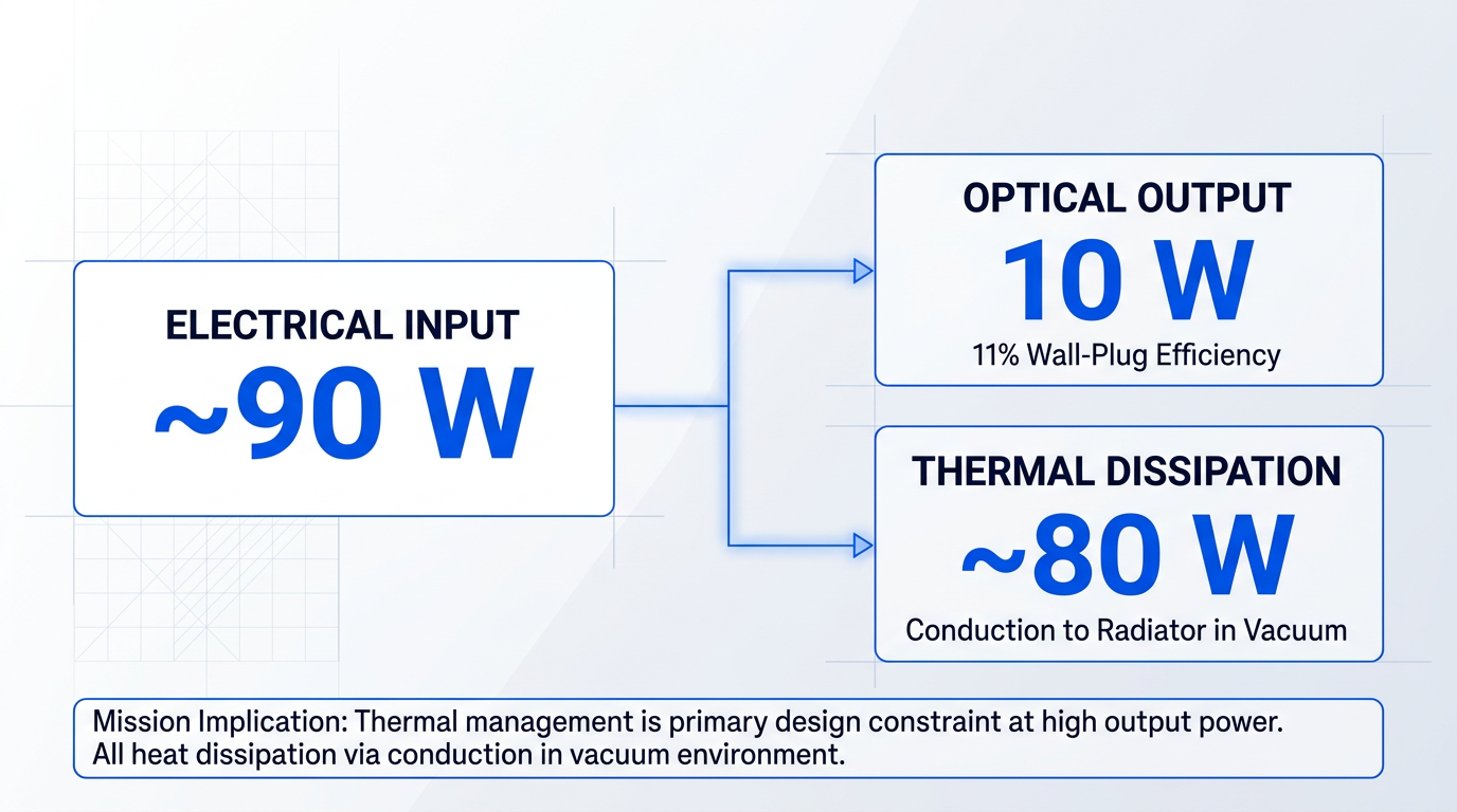
The ESA-funded 10 W PM EDFA development by MPBC demonstrated a wall-plug efficiency of 11% at 10 W optical output in vacuum testing, which implies roughly 80–90 W of total electrical power consumption to sustain that output level.
In a vacuum environment, where convective cooling is absent, that thermal load must be dissipated entirely through conduction to a radiator — making thermal management a primary design challenge rather than an implementation detail, particularly as output power scales upward.
For missions using coherent modulation formats such as DPSK or QPSK, the amplifier must also deliver polarisation-maintaining (PM) output — a requirement that adds component complexity and cost but is non-negotiable for these waveforms. The relevant specification is polarisation extinction ratio (PER), with commercial PM EDFAs typically specifying a minimum of 20 dB and a typical value of 23 dB.
Finally, every performance parameter discussed in this section must be met not just at launch, but across the full mission lifetime. The radiation-induced gain degradation and pump laser diode ageing covered in the qualification section both erode amplifier output over time, meaning that end-of-life (EOL) power margin must be designed in from the outset — it cannot be retrofitted once the mission is in orbit.
With the performance requirements now framed as mission decision axes — output power derived from the link budget, noise figure governed by amplifier role, SWaP treated as a co-equal constraint, and EOL margin built in from day one — the logical next question is what level of qualification assurance is actually needed to reliably meet those specifications across the mission lifetime, and what that choice costs in time and budget.
COTS vs Space-Qualified Components: Engineering the Right Choice
The framing of "COTS versus space-qualified" implies a binary that does not exist in practice. The COTS spectrum runs from unscreened commercial catalogue parts at one end, through Telcordia-qualified telecom components, through lot-screened and upscreened parts, to fully space-qualified hardware with traceable flight heritage at the other.
The engineering question is never which category a component falls into — it is which level of assurance the mission actually requires. Answering that question demands a structured framework, not intuition.
The MEAL Framework for Qualification Decisions
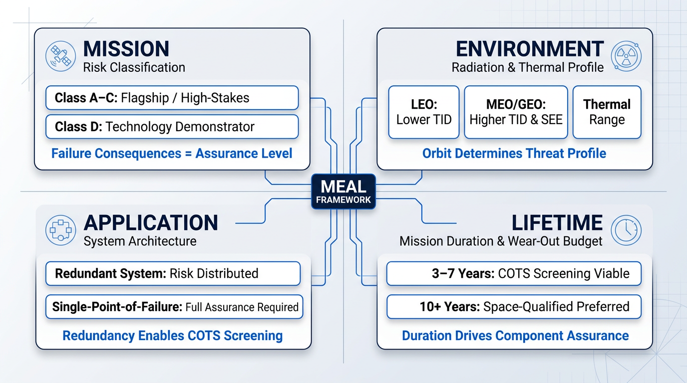
- Mission risk classification: Is this a Class A flagship mission where failure is unacceptable, or a Class D technology demonstrator where risk tolerance is explicitly higher?
- Environment: What are the radiation, thermal, and vacuum exposure levels? LEO, MEO, and GEO present fundamentally different TID and SEE threat profiles.
- Application: Is the amplifier a single-point-of-failure element, or does the system architecture provide redundancy or graceful degradation pathways?
- Lifetime: A 3-year LEO constellation node has a very different wear-out budget than a 15-year GEO communications payload operating continuously.
The four MEAL framework factors interact: no single factor determines the answer alone. A short-lifetime LEO mission with a redundant architecture and a relatively benign radiation environment can justify a rigorous COTS-with-screening approach; a 15-year GEO mission with a single-point-of-failure amplifier cannot.
When COTS-with-Screening Is the Right Engineering Choice
For new-space constellation operators deploying large numbers of identical satellites on 3–7 year orbital lifetimes, a well-executed COTS-with-screening approach is not a compromise — it is the appropriate engineering response to the mission context. Cost-effective, volume-producible amplifier solutions are a genuine programme requirement in this market, and the industry has developed rigorous screening methodologies to meet it.
What that screening actually involves, however, is frequently misunderstood. Selecting COTS components for space use is not a catalogue exercise — it is a structured engineering campaign that must be planned from programme outset.
- Lot-level functional testing: Verify that the specific production lot meets optical and electrical specifications before any further investment in that component selection.
- Environmental testing: Thermal-vacuum, vibration, and shock testing on representative samples from the flight lot — not on prior-generation or datasheet references.
- Radiation testing: TID and SEE characterisation performed early in the component selection phase, before design commitment. Timing here is critical.
- Destructive physical analysis: Also called construction analysis, DPA examines packaging and internal construction to identify failure modes before they are designed into the system.
- Workmanship screening: Burn-in and visual inspection to remove infant-mortality failures from the flight population before integration.
Taken together, this process demands engineering discipline, dedicated test resource, and significant schedule allocation — it is closer in character to a qualification campaign than to a procurement activity.
A rigorous COTS screening programme for space use is not a shortcut. It requires comparable engineering effort to a formal qualification campaign — the distinction lies in traceability depth, heritage documentation, and the breadth of the assurance envelope, not in the amount of work involved.
Where the COTS-with-screening envelope becomes too wide is on missions where failure consequences are severe and unquantifiable risk is unacceptable: long-lifetime programmes (10+ years), high-radiation environments such as MEO and GEO, single-point-of-failure amplifier applications, and Class A through C missions.
Fully space-qualified components carry traceable lot data, documented qualification reports, and demonstrated flight heritage — not as bureaucratic formality, but as substantive risk mitigation for programmes where the cost of failure vastly exceeds the cost of assurance.
NRE Costs and the Economics of Customisation
Non-recurring engineering (NRE) costs for a custom space-qualified amplifier module cover thermal and structural analysis, radiation analysis, engineering model build, the qualification campaign itself, and the associated documentation package. These are real programme costs that must be weighed explicitly against the mission risk of using a less-qualified alternative.
The economics shift substantially with production volume. For a large constellation requiring hundreds of identical units, NRE is amortised across the production run — which can make a fully engineered, purpose-qualified solution competitive with a screened COTS approach on a per-unit basis, while delivering a deeper assurance envelope.
Telcordia-qualified telecom components — particularly relevant for EDFAs, given their shared heritage with the terrestrial fibre communications industry — are a useful starting point for space upscreening because their shock, vibration, and thermal test regimes overlap meaningfully with many space requirements.
The critical nuance is that Telcordia qualification attests to the manufacturer's process and production line, not to the specific lot of parts that will fly. Lot-level screening and radiation testing remain mandatory for flight use, even when the component carries Telcordia certification — buyers who treat Telcordia qualification as sufficient for space without further screening are accepting undisclosed risk.
On the programme management side, the single highest-leverage decision is the timing of radiation testing: it must happen in the component selection phase, before the design is committed to a specific part. Discovering radiation sensitivity after PCB layout is finalised and the schedule is set is disproportionately disruptive and expensive to resolve.
With the MEAL framework established and the COTS trade-off mapped, the practical question becomes how these decisions play out across different satellite platforms — the subject of the next section, which applies this framework to CubeSat, LEO, and GEO mission contexts specifically.
Integration Considerations by Platform: CubeSat, LEO, and GEO
The same EDFA technology that flies on a GEO relay satellite can, in principle, sit inside a CubeSat optical terminal — but the engineering decisions surrounding it will look almost nothing alike. Platform class is the primary determinant of amplifier selection, more so than any single specification on a datasheet: it sets the SWaP budget, the qualification level required, the radiation tolerance needed, and the acceptable unit cost. Understanding where your mission sits across these three platform contexts is what converts specification knowledge into a procurement decision.
CubeSat and Small Satellite Platforms
On CubeSat and small satellite platforms, SWaP is the binding design variable in a way it simply is not on larger spacecraft — amplifier mass, volume, and power draw often constrain the entire optical terminal design before optical performance parameters are even considered.
The thermal management challenge on a CubeSat chassis is particularly acute: with limited radiator area in vacuum and no convective cooling available, heat generated by the amplifier must be conducted through the structure itself, which places a practical ceiling on achievable output power even when the optical link budget could support more.
CubeSats using body-pointing architectures — those without fine-pointing assemblies — must compensate for pointing loss with higher transmit power, which pushes amplifier output power upward precisely when the SWaP budget is pushing it down; this tension is one of the defining engineering trade-offs in small satellite FSOC terminal design.
The COTS-with-screening approach discussed earlier in this guide is particularly rational for CubeSat missions: shorter lifetimes, lower cumulative radiation doses, and tight programme budgets make full space qualification disproportionate for many small satellite applications, and lot-level screening of telecom-grade components offers a defensible middle path.
Concrete form factors are now available that make CubeSat FSOC viable: the Polaris Photonics EDFA-27-SP, for example, is a space-grade EDFA delivering 500 mW minimum saturated output power at 1550 nm, with a 4.5 dB noise figure, in a 140 × 130 × 32 mm package qualified to ISO 19683:2017 and designed explicitly for CubeSat optical communications terminals and SDA v3.0 compatibility.
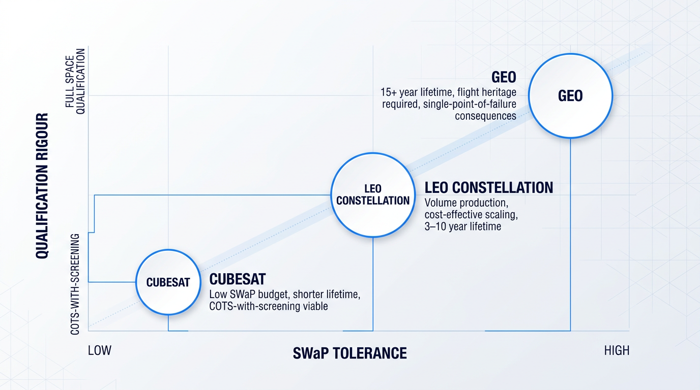
The infographic above captures the core trade-off space: as platform class scales from CubeSat to GEO, SWaP tolerance increases and the qualification bar rises in lockstep — these two axes together define where a given mission sits in the amplifier selection landscape.
LEO Constellation Applications
LEO constellations represent the largest current demand driver for space-grade optical amplifiers, with new-space programmes deploying inter-satellite links (ISLs) and satellite-to-ground FSOC links at a scale that is establishing volume production economics for the entire industry.
The amplifier requirement profile for LEO constellation applications, as characterised in SPIE proceedings on high-efficiency fibre optic amplifiers for new-space constellation applications, centres on: low noise figure, high gain across the 1535–1565 nm C-band, output powers in the 1–10 W range, high wall-plug efficiency (because electrical power budgets are constrained and thermal dissipation in vacuum is challenging), and radiation tolerance sized for 3–10 year mission lifetimes.
The factor that most distinguishes LEO constellation procurement from a one-off GEO programme is cost-effective production at scale: deploying hundreds or thousands of amplifiers per constellation drives vendors toward ruggedised COTS-based packaging approaches and scalable manufacturing models that differ materially from traditional space qualification workflows.
GEO and Long-Distance Links
GEO missions invert the LEO constellation calculus: with typical design lifetimes of 15 or more years, higher cumulative radiation doses, and single-point-of-failure consequences for the satellite operator, full space qualification with traceable flight heritage is not a procurement preference — it is a programme requirement.
The LUCAS programme provides the most concrete available reference for what GEO-class qualification looks like in practice: two optical amplifier systems — a high-power booster and a low-noise pre-amplifier — were built for JAXA's Optical Data Relay Satellite, which achieved 1.8 Gbps inter-satellite optical communication at 1.55 μm over approximately 40,000 km between the GEO relay satellite and the ALOS-4 earth observation satellite in LEO.
The LUCAS amplifier flight models passed system-level acceptance testing covering mechanical shock, vibration, and vacuum operation — and according to their manufacturer, at time of launch they represented the first 1.55 μm optical fibre amplifiers ever deployed in GEO orbit.
GEO amplifiers must also maintain specified performance across the full mission lifetime, accounting for pump laser diode ageing, radiation-induced gain degradation, and accumulated thermal cycling — the performance margin and end-of-life budgeting concepts covered earlier in this guide apply with particular force here, where there is no opportunity for on-orbit replacement.
GEO-to-ground and deep-space links demand higher transmit powers than LEO-to-ground applications, which drives multi-stage amplifier architectures to reach 5–10 W output levels; the ESA 10 W PM EDFA programme, completed by MPB, developed a polarisation-maintaining fibre amplifier at 1550 nm for space applications targeting 10 W at end of life for high-speed inter-satellite and satellite-to-ground links.
At these power levels, stimulated Brillouin scattering (SBS) becomes the key nonlinear constraint: SBS limits power scaling in narrow-linewidth single-mode fibre and becomes a design challenge above approximately 1–2 W, meaning that reaching 10 W output requires active mitigation — the ESA programme addressed this through an innovative proprietary method to avoid SBS, illustrating that high-power space amplifier design is as much about nonlinear management as it is about gain.
Platform class determines qualification level required and SWaP tolerance available simultaneously — and these two axes together define the amplifier selection space more completely than any single performance specification.
Inter-satellite link (ISL) amplifiers combine several of the most demanding requirements in one package: the high output powers needed for long-distance links, polarisation-maintaining fibre output for coherent modulation formats, compact packaging to fit within the optical terminal, and the radiation tolerance and lifetime margins appropriate to the host platform.
The Space Development Agency (SDA) Optical Communications Terminal standard — currently at version 3.2.0 (April 2025) and version 4.0.0 (July 2024) — is an increasingly important reference framework for ISL terminal specifications, defining duplex operation at 1536.61 nm and 1553.33 nm within the optical C-band, maximum transmitted power flux of no less than 2.5 W, and full-duplex data rates up to 2.5 Gbps; amplifiers destined for SDA-aligned terminals must be designed to these channel and power parameters.
At the physical integration level, virtually all space FSOC systems use single-mode fibre coupling between the amplifier output and the telescope or optical head — amplifier output must be single-spatial-mode and compatible with the terminal's fibre interface, with PM fibre required wherever coherent modulation formats are used, as established earlier in this guide.
With a clear picture of how platform class shapes amplifier requirements across CubeSat, LEO, and GEO contexts, the natural next question is how to evaluate which vendors can actually meet those requirements — and that is where the following section focuses.
How to Evaluate Space-Heritage Optical Amplifier Vendors
The phrase "space-grade" appears on a remarkable number of supplier websites — and it means almost nothing without the evidence to back it up. Having established what qualification entails for your orbit class and platform, the next practical challenge is distinguishing a vendor who has genuinely done that work from one who has adopted the language without the substance.
The difference between a credible space-heritage vendor and a commercial supplier making aspirational claims rarely shows up in a brochure. It shows up in the specificity of what they can produce when you ask for it — traceable test data, qualification documentation, and programme experience they can evidence under NDA.
Flight Heritage: What Traceable Evidence Looks Like
The first question to put to any vendor is not "have you flown hardware in space?" but "which orbit classes, what qualification evidence, and can we review it under NDA?" A vendor with genuine flight heritage can answer all three without hesitation.
To understand what traceable heritage looks like in practice, consider the LUCAS programme — a laser communication system developed by NEC Corporation for JAXA, deployed aboard Japan's Optical Data Relay Satellite in GEO orbit, linking to LEO earth observation satellites including DAICHI-4 at a recorded inter-satellite data rate of 1.8 Gbps at 1.5 μm wavelength over 40,000 km.
Similarly, NASA's LLCD (Lunar Lasercom Demonstration) and LCRD (Laser Communications Relay Demonstration) programmes represent the kind of documented, agency-backed qualification practice that sets the benchmark for vendor evidence — with fibre optic components validated through mission-specific upscreening programmes tailored to each mission's radiation, thermal, and vibration environment.
The standard to apply is simple: ask for evidence, not names. Customer and programme names are often confidential, so a credible vendor will instead share qualification reports, test data and orbit-class experience under NDA.
Qualification Data Traceability
Vendors with genuine space heritage can produce qualification reports — not a statement of compliance or a reference to a standard, but actual environmental test data tied to specific component lots. Ask which standards were applied (ECSS, MIL-SPEC, ESA/SCC), whether testing was conducted by an independent test house, and critically, whether the qualification data covers the specific lot being proposed for your programme.
NASA's qualification guidelines for optoelectronic and photonic devices make clear that qualification proceeds through distinct stages: company certification, process qualification, product qualification, and product acceptance — each generating its own documentation trail. A vendor who has executed this process will be able to walk you through each stage with documentation shared under NDA; one who hasn't will speak only in generalities.
Radiation Test Data: Where Superficial Vendors Are Exposed
Radiation testing is the area where the gap between genuine space heritage and aspirational positioning is most starkly revealed. A system-level TID claim tells you almost nothing useful; what matters is component-level TID test data on the doped fibre, the pump laser diodes, and the control electronics — tested separately, not as an undifferentiated assembly.
Ask specifically about the dose levels tested, the dose rates used during testing, and whether any predictive models were applied to extrapolate end-of-life performance at the mission's actual on-orbit dose rate. This matters because dose-rate effects can differ significantly from total-dose effects — a fact well-established in NASA and ESA radiation effects literature — and a high-rate laboratory test may not accurately predict behaviour at the low dose rates typical of operational GEO or LEO environments.
For doped fibres specifically, the radiation sensitivity is strongly dependent on fibre dopant composition — aluminium content in erbium-doped fibre, for instance, is a known driver of radiation-induced attenuation — and a vendor with genuine expertise will be able to discuss the fibre composition they use and the measured radiation performance at relevant dose rates.
Vendors who have done this work will have the data, organised by component lot. Those who haven't will deflect toward system-level claims or reference a standard without providing the underlying test results.
Vertical Integration Depth
A vendor who designs and manufactures their own doped fibres, pump laser modules, and passive components — WDMs, isolators, couplers — has end-to-end control over qualification traceability and supply chain stability that an assembler of third-party components simply cannot match.
When a vendor sources pump laser diodes and doped fibre from external suppliers, their visibility into the provenance, lot history, and radiation characterisation of each sub-component is limited to whatever the sub-supplier chooses to share. In a space programme context, that gap in traceability is a material risk.
Assess how much of the optical train the vendor actually owns — from fibre draw to final assembly — and treat deep vertical integration as a meaningful positive signal when evaluating space-qualified amplifier suppliers.
ESA and NASA Programme Experience as a Proxy
Engineering capability and programme management capability are not the same thing. A vendor who has delivered hardware to ESA or NASA has been tested by the documentation discipline, non-conformance management processes, and acceptance review structures that govern serious space programmes — and that experience is a meaningful proxy for their ability to execute on your programme.
Ask whether the vendor can describe their experience with a Preliminary Design Review (PDR), Critical Design Review (CDR), or Qualification Review, and whether they can share the review evidence under NDA. A vendor who has navigated these structures for a real customer — for example, under an ESA Scylight framework contract or a JAXA programme — is demonstrably different from one who cannot contextualise those terms in their own project history.
NRE Transparency and Customisation Scope
Non-recurring engineering costs for a custom space-qualified amplifier module can be significant, and what is included in an NRE quote varies enormously between vendors. A credible NRE scope should be itemisable: thermal analysis, structural analysis, radiation analysis, engineering model (EM) build, qualification campaign, and documentation package — each a distinct, costed activity.
A vendor who quotes NRE as a single undifferentiated figure — or who cannot describe what their qualification campaign entails — is unlikely to have executed a full qualification programme before. The ability to itemise these components is itself a signal of programme experience, not just engineering competence.
Supply Chain and Obsolescence Management
Space programmes have development timelines measured in years, and the components that underpin a space-qualified amplifier — particularly pump laser diodes — carry their own obsolescence risk. For a GEO mission with a 15-year operational lifetime, the pump diodes selected at CDR may face end-of-life from their manufacturer before the satellite is decommissioned.
NASA's DMSMS (Diminishing Manufacturing Sources and Material Shortages) guidance and ESA's REACH obsolescence management framework both identify lifetime lot-buy strategies as a primary mitigation for this risk — procuring sufficient quantities of a qualified part to sustain the programme, with traceability to a common material lot and manufacturing run date maintained throughout.
Ask any prospective vendor about their lot traceability process for pump laser diodes, how they manage process changes at sub-suppliers that could affect qualification status, and what their policy is when a critical component approaches end-of-life. A vendor with a mature supply chain programme will have documented answers; one without will be working through the question for the first time in front of you.
Any vendor can describe their hardware as space-grade. Only a vendor with genuine space heritage can produce qualification reports, component-level radiation test data, and lot traceability documentation tied to specific component lots, shared under NDA where customer names are confidential — and the difference between the two is exactly what your first vendor meeting should establish.
The following questions are designed to be put directly to any prospective vendor — in a first meeting, an RFI, or a technical interchange. The answers are not pass/fail checkboxes; they reveal the depth of a vendor's actual space-heritage experience, and the contrast between specific, evidenced responses and vague generalities is itself the evaluation.
- Describe the flight experience: Which orbit classes have your amplifiers flown in, and what qualification evidence can you share under NDA? Customer names are often confidential.
- Provide the qualification data: Can you supply qualification reports and radiation test data for the specific component lot you are proposing for our programme?
- Explain lot traceability: What is your process for maintaining lot traceability from raw fibre and pump diode procurement through to final assembly and acceptance?
- Describe radiation testing depth: Were your doped fibre, pump laser diodes, and control electronics tested for TID separately? At what dose levels and dose rates?
- Clarify vertical integration scope: Which elements of the optical train — doped fibre, pump modules, passive components — do you design and manufacture in-house?
- Describe programme review experience: Have you participated in a PDR, CDR, or Qualification Review for an ESA or NASA programme? In what role, and can you share the review evidence under NDA?
- Itemise the NRE scope: What does your NRE scope include for a custom module — thermal analysis, structural analysis, EM build, qualification campaign, documentation package?
- Explain obsolescence management: What is your lifetime lot-buy policy for pump laser diodes, and how do you manage sub-supplier process changes that could affect qualification status?
With a clear vendor evaluation framework in hand, the final step is consolidating all of the criteria covered across this guide — amplifier technology selection, qualification methodology, performance parameters, COTS trade-offs, platform-specific requirements, and vendor evaluation — into a coherent, actionable selection process, which the concluding section brings together.
Conclusion
Building Your Selection Framework
Every decision in this domain rewards the same discipline: treat amplifier selection as a systems exercise, not a specification search, and commit to qualification decisions early — before design lock, before vendor engagement, before the programme schedule makes late changes expensive.
You are now positioned to define your MEAL parameters before approaching suppliers, request traceable qualification and radiation test data rather than accepting marketing language, and evaluate flight heritage against your specific orbit class.
Frequently Asked Questions
Precise answers to the procurement, qualification, and technical questions most commonly raised about space-qualified optical amplifiers — from radiation dose planning to lead times and SBS mitigation.
"Space-grade" is a marketing term with no standardised definition — any supplier can apply it without evidence. "Space-qualified" implies a documented qualification programme conducted against defined standards such as ECSS, MIL-SPEC, or the NASA EEE parts methodology, with traceable test reports to back the claim. The distinction matters enormously at procurement. Always ask for the specific qualification evidence: radiation test reports, the standards applied, lot traceability documentation, and environmental test data covering thermal-vacuum, vibration, and shock. A supplier who cannot produce these artefacts has not qualified their product — regardless of what their datasheet says. As NASA GSFC photonics qualification guidance makes clear, even previously Telcordia-qualified components must undergo lot-level flight screening and qualification testing to certify they meet a specific mission's requirements. The label tells you nothing; the evidence tells you everything.
As a planning-level ballpark for a 7-year mission with typical aluminium shielding: LEO approximately 5–10 krad(Si), MEO approximately 10–100 krad(Si), and GEO approximately 50 krad(Si). These figures are starting points only — not component specifications. Mission-specific radiation analysis using tools such as SPENVIS or SHIELDOSE-2, informed by actual orbit parameters, shielding geometry, and mission duration, is always required before committing to part-level TID requirements. This is the process mandated by ECSS-Q-ST-60-15C Rev.1, the current radiation hardness assurance standard. For LEO missions, the South Atlantic Anomaly is the dominant contributor to trapped proton dose and must be explicitly modelled — inclination and altitude both shift the exposure significantly. MEO spans the Van Allen belts and can produce the harshest TID environments of any operational orbit class. Engage a radiation analyst early; the figures above are enough to open a conversation with a vendor, but mission-specific analysis must precede any component specification.
Coherent modulation formats — specifically DPSK and QPSK — used in high-data-rate free-space optical communications links require a defined, stable polarisation state at the amplifier output. PM fibre maintains this polarisation through the gain medium by preserving the electric field orientation along a defined axis, preventing the polarisation mixing that standard single-mode fibre would allow under thermal and mechanical stress. The practical specification consequence is a polarisation extinction ratio (PER) requirement, typically greater than 20 dB, which must be maintained across the full operating temperature range. Thermal cycling can degrade PER if fibre routing and splicing are not carefully managed — a real design and assembly discipline, not just a material selection. PM amplifiers carry a cost and complexity premium over non-PM variants. Importantly, not every FSOC application requires PM: intensity-modulated direct-detection (IM-DD) links do not require polarisation control. The requirement is modulation-format-dependent, so confirm your link's modulation scheme before specifying PM.
There is no honest answer without performing a link budget first. The required output power depends on slant range at the relevant elevation angle, transmit and receive aperture sizes, pointing loss, atmospheric loss (including turbulence, cloud obscuration, and absorption), required data rate, modulation format, and receiver sensitivity — all of which vary by mission. That said, 1–10 W class amplifiers (approximately +30 to +40 dBm saturated output) are typical for LEO constellation downlink applications. The ESA 10 W PM EDFA programme at 1550 nm represents the current upper end of demonstrated space-grade EDFA output power for this application class, and published SPIE literature on new-space constellation amplifiers confirms that the 1–10 W range covers the majority of operational downlink designs. Start with the link budget. Specifying a power class first and working backwards is a common procurement mistake that leads to either over-engineered hardware or a link that cannot close.
Stimulated Brillouin scattering (SBS) is a nonlinear optical effect in which photons scatter off acoustic phonons in the fibre, generating a backward-propagating Stokes wave that limits the forward power that can be transmitted. In narrow-linewidth fibre amplifiers it becomes a practical design constraint at watt-class output powers in standard single-mode fibre. Three principal mitigation strategies are used in space amplifier design. First, large-mode-area (LMA) fibre increases the effective mode area, raising the SBS threshold. Second, phase modulation of the seed signal broadens the optical linewidth, distributing the Brillouin gain across a wider frequency range and reducing its peak. Third, multi-stage amplifier architectures distribute gain across stages rather than concentrating it in a single high-power stage. The ESA 10 W PM EDFA programme at 1550 nm is an instructive real-world case: achieving SBS-free operation at 10 W output required an innovative proprietary approach, and the ESA Resilience project developing a high-power 1064 nm amplifier similarly identified SBS avoidance as a primary design challenge. At 10 W and above, SBS is not a secondary consideration — it is a first-order design constraint that shapes the entire amplifier architecture.
No — unmodified COTS telecom EDFAs are not suitable for space use. Three principal reasons apply. First, materials used in COTS telecom packaging may outgas in vacuum, contaminating optical surfaces and adjacent spacecraft components — NASA qualification guidelines require all non-metallic materials to meet total mass loss (TML) and collected volatile condensable materials (CVCM) limits per ASTM-E595. Second, COTS telecom amplifiers use standard doped fibres and electronic components that are not radiation-hardened and will degrade under the TID levels encountered in orbit. Third, they have not been tested to the launch vibration and shock profiles required for spacecraft components. The important nuance is that COTS telecom components — including Telcordia-qualified EDFAs — can be a legitimate starting point for a ruggedised space amplifier when subjected to appropriate lot-level screening, upscreening, radiation testing, and environmental qualification. NASA GSFC photonics qualification practice and the Spellmeyer NASA NTRS paper on emerging space laser comm both confirm this COTS-with-screening approach as an established methodology. The starting point is acceptable; unmodified use is not.
Lead times vary significantly depending on the qualification level required and the vendor's existing heritage — there is no single answer. A COTS-based ruggedised amplifier with lot screening and basic environmental testing may be achievable in a matter of months if the vendor has an existing design close to the required specification. A fully space-qualified custom module — including engineering model build, full qualification campaign covering thermal-vacuum, vibration, shock, and radiation, plus documentation package and acceptance review — can take 18–36 months or more from programme start. ESA guidance on bespoke space-qualified component development cites two to five years as typical for a fully new design, with 18 months as a lower bound only when significant design reuse is possible. The practical implication is straightforward: engage vendors before the mission PDR if at all possible, and treat amplifier qualification as a programme-schedule constraint from day one. Programmes that discover this late pay a disproportionate price — in schedule pressure, in cost, and sometimes in compromised qualification rigour.