

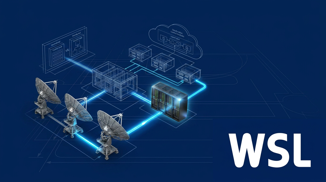
Introduction
If you are an engineer, programme manager, or mission architect preparing to make real architectural decisions, you have likely already read the overviews — the ones that list what a satellite ground system contains without ever explaining why it is designed the way it is.
The reasoning behind each choice is what this page is about: not a component inventory, but the logic that connects mission requirements to architectural commitments.
Work through the sequence here and you will be able to approach each decision as a deliberate trade-off, understanding what drives it and what it forecloses.
The structure follows the order a practitioner actually works through — from requirements and topology through link architecture, modern software paradigms, standards selection, and resilience design.
TL;DR
Ground system architecture is not a procurement exercise. Every structural commitment — topology, link modality, software paradigm, standards choice — carries consequences that compound over the mission's lifetime. The order in which you make those decisions matters as much as the decisions themselves: locking in the wrong thing early is far costlier than working through the trade-offs in the right sequence.
This article covers:

Mission requirements as architectural drivers
Component integration and network topology decisions
Communication link architecture: RF vs optical
Software-defined, virtualised, cloud-native architectures
Standards and interoperability choices
Cybersecurity and resilience by design
Satellite Ground System: Architecture, Scope, and Design Dimensions
Most ground system failures trace back not to faulty hardware but to faulty decisions — topology choices made without trade-off analysis, standards adopted inconsistently, redundancy bolted on after the fact. Understanding a satellite ground system as an architecture rather than an inventory is the starting point for avoiding that pattern.
Architecture, in this context, is the ensemble of design decisions that governs how the ground-based elements integrate, communicate, and interact with one another and with the spacecraft. It is defined not by what the system contains but by the relationships and trade-offs that govern how those elements are wired together.
The Four Primary Functional Elements
NASA's Ground Data Systems State of the Art reports define four primary elements that make up any ground system, from a small satellite mission to a deep-space observatory.
- Ground Stations: Physical antenna sites that form the telemetry, tracking, and command (TT&C) interface between the ground segment and the spacecraft.
- Ground Networks: The connectivity infrastructure — data links, IP networks, dedicated lines — that ties multiple ground elements into a coherent system.
- Control Centres: The Mission Operations Centre (MOC) and Science Operations Centre (SOC), responsible for spacecraft operations management and science/payload operations respectively.
- Remote Terminals: The user-facing endpoints through which mission data reaches operators and scientists for additional processing and dissemination.
The Mission Operations Centre (MOC) sits at the hub of this architecture: all commands to the spacecraft originate from or pass through it, and all telemetry from the spacecraft is routed back to it for monitoring, distribution, and archiving.
The Science Operations Centre (SOC) is a distinct entity — responsible for generating science data products and determining payload operations — but it interfaces directly with the MOC, which remains the sole authoritative command interface to the spacecraft. ESA's mission documentation for programmes including Gaia, Integral, and Venus Express confirms this division: the MOC holds spacecraft command authority while the SOC drives payload and instrument scheduling.
The first topology question a designer encounters is whether the spacecraft communicates via Direct-to-Earth (DTE) links or through a space relay. DTE provides direct line-of-sight contact via ground stations, while relay services use intermediate satellites in geosynchronous orbit to extend coverage and reduce contact gaps. According to NASA's SOA GDS series, DTE is particularly effective for missions needing frequent, high-throughput contacts, whereas space relay is better suited to missions requiring continuous coverage or low-latency messaging. The choice between them is an architectural decision with downstream consequences for ground station selection, network design, and operations planning — and it is one of the first trade-offs the subsequent steps will unpack.
The Design Dimensions This Page Addresses
The six steps that follow each address one major design dimension of ground system architecture, in the sequence a designer would naturally encounter them.
- Mission requirements as architectural drivers: Translating what the spacecraft must do into specific demands on the ground segment.
- Component integration and network topology: Deciding how ground stations, control centres, and networks are connected and organised.
- Communication link architecture: Designing the RF and optical link layer that connects space and ground segments.
- Software-defined and cloud-native paradigms: Applying virtualisation, software-defined ground systems, and cloud infrastructure to ground operations.
- Standards and interoperability: Selecting and applying interface standards that enable multi-mission and multi-agency compatibility.
- Cybersecurity and resilience: Designing threat resistance and operational continuity into the architecture from the outset.
Each dimension constrains the next: the mission requirements shape the topology, the topology shapes the link architecture, and the link architecture shapes what software and standards choices are viable. Decisions made in the early dimensions narrow the solution space available in later ones.
Topology changes, standards migrations, and resilience retrofits applied to a partially-built ground system cost significantly more than equivalent decisions made at the concept phase — and they arrive at the worst possible moment, when integration and test schedules are already under pressure.
With that conceptual map in place, the logical starting point is the mission itself: what the spacecraft is designed to do, and what those objectives demand of every element in the ground segment.
Step 1
Translate mission requirements into architectural drivers
Key Insights
Architecture derives from mission requirements, not best practice.
LEO passes last minutes — single-site architectures fail.
Mission type determines which trade-offs are available.
Produce a documented requirements-to-constraints matrix.
Start with the mission, not the hardware. Your satellite ground system architecture is not a product of generic best practice or a template inherited from a previous programme — it is a direct derivation of what this specific mission demands. Topology, redundancy levels, processing architecture, MOC configuration: all of these follow from requirements, and getting that sequence wrong means redesigning under pressure later.
Identify and document every mission parameter that carries an architectural implication before you make a single design decision. The categories below are the ones that cascade most directly into ground segment constraints.
Requirement categories that drive ground segment design
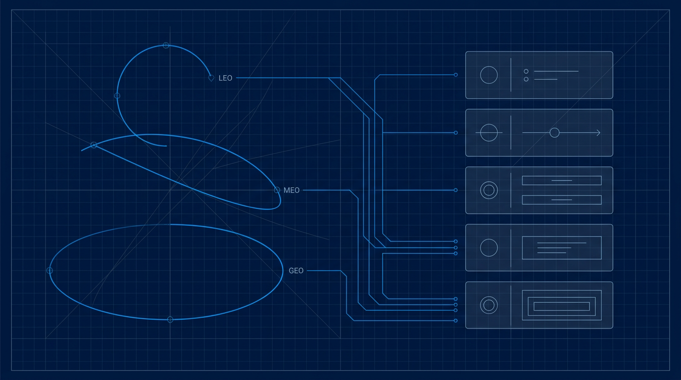
- Orbit regime: LEO, MEO, GEO, and deep space each impose fundamentally different contact geometry on the ground segment. Orbit regime is the single most consequential input to your architecture — establish it first.
- Contact frequency and duration: How often the spacecraft is visible to a given ground station, and for how long per pass. A LEO satellite in a typical low-inclination orbit may be above a single station's horizon for only 8–12 minutes per pass. This is not an operational constraint — it is an architectural one.
- Data volume and timeliness: Determine whether your mission requires near-real-time downlink (Earth observation, surveillance) or can tolerate store-and-forward delivery (deep-space telemetry, non-time-critical science data). This is an architectural fork: the two models drive fundamentally different ground processing and network designs.
- Command latency tolerance: How quickly must the spacecraft respond to commands from the ground? This constrains both the MOC architecture and the acceptable propagation delay through the ground network routing path. A mission with tight latency requirements cannot absorb arbitrary relay hops.
- Availability and continuity: What percentage of time must the ground segment maintain contact capability, and what is the consequence of a contact gap? High-availability requirements drive redundancy architecture — geographically separated backup stations, diverse routing paths, and failover procedures are all availability answers, not safety gold-plating.
Once you have these parameters characterised, map each one to its direct architectural implication before moving on. Leaving any of them as informal assumptions is how design debt accumulates.
How mission type shapes the architectural envelope
Beyond the specific parameters above, the broad mission category constrains which trade-offs are even available to you as a designer. Understand your mission type before evaluating options.
- Defence missions: Sovereignty of command authority, hardening against interference and intrusion, and the ability to operate without dependence on foreign ground infrastructure are architectural requirements from the outset — not features added later. These constraints narrow the design space significantly before any parameter-level analysis begins.
- Civil and scientific missions: Interoperability with agency networks, compliance with internationally recognised standards, and the ability to share ground assets across missions are primary architectural considerations. The design must accommodate cross-support arrangements from day one.
- Commercial missions: Time-to-orbit, cost efficiency, scalability as a constellation grows, and the ability to leverage commercially available ground infrastructure shape the envelope. The commercial designer has access to trade-offs — including Ground Segment as a Service — that are not available to a sovereign defence programme.
This is not a classification exercise. It is a recognition that your mission type determines which architectural options are on the table and which are not, before you evaluate any of them.
A LEO satellite passes above any given ground station for only a few minutes per pass. A ground architecture built around a single fixed station will have large, predictable coverage gaps — not as an edge case, but as a structural property of the orbit. The architectural implication is clear: LEO missions require either a distributed network of geographically separated stations or access to a globally distributed antenna network through a service provider. GEO missions, by contrast, allow a single well-sited station to maintain near-continuous contact — making single-site architectures viable in a way they simply are not for LEO. Establish which regime you are in, and let that fact drive your topology requirements into Step 2.
Bandwidth and latency requirements do not sit in isolation — they cascade. A high data-volume mission with strict timeliness requirements drives the need for higher-throughput downlinks, which in turn drives antenna aperture and ground station hardware specification, which drives how many stations you need to sustain the required aggregate contact time across the orbit.
Similarly, command latency tolerance constrains the acceptable routing path between the MOC and the ground station. Map these cascades explicitly: each constraint you identify will surface dependencies that are far easier to resolve now than after your topology is fixed.
The output: a requirements matrix
You have completed this step when you have a documented requirements matrix — sometimes called a ground system requirements document or architectural drivers document — that maps each mission parameter to one or more concrete architectural constraints. This is not a summary slide; it is the governing input to every design decision that follows.
The matrix should capture orbit regime and resulting contact geometry, data volume and timeliness classification, command latency bounds, availability targets, and the mission-type constraints that bound your option space. Capture it as an explicit, versioned artefact — informal assumptions held in team memory are not requirements, and they will not survive a programme review or a handover.
With this matrix in hand, you are ready to move to Step 2: translating your coverage and topology requirements into a ground network architecture.
Step 2
Define the Component Integration Architecture and Network Topology
Key Insights
Integration architecture and network topology are separate decisions.
Centralised MOC simplifies control but risks single failure.
LEO contact frequency demands multi-site ground topology.
Choose an open-architecture framework before procuring components.
With your requirements matrix from Step 1 in hand, the next set of decisions is structural. You are now choosing two things that are related but distinct: the integration architecture — how your ground segment components connect and exchange data at the logical and software layer — and the network topology — how your ground sites are physically and logically arranged across geography.
These are separable decisions that interact. Confusing them leads to topology choices that cannot be supported by the integration layer, or integration frameworks that cannot scale to the topology the mission needs. Treat each as a deliberate design choice with long-term consequences.
Centralised vs. Distributed Control
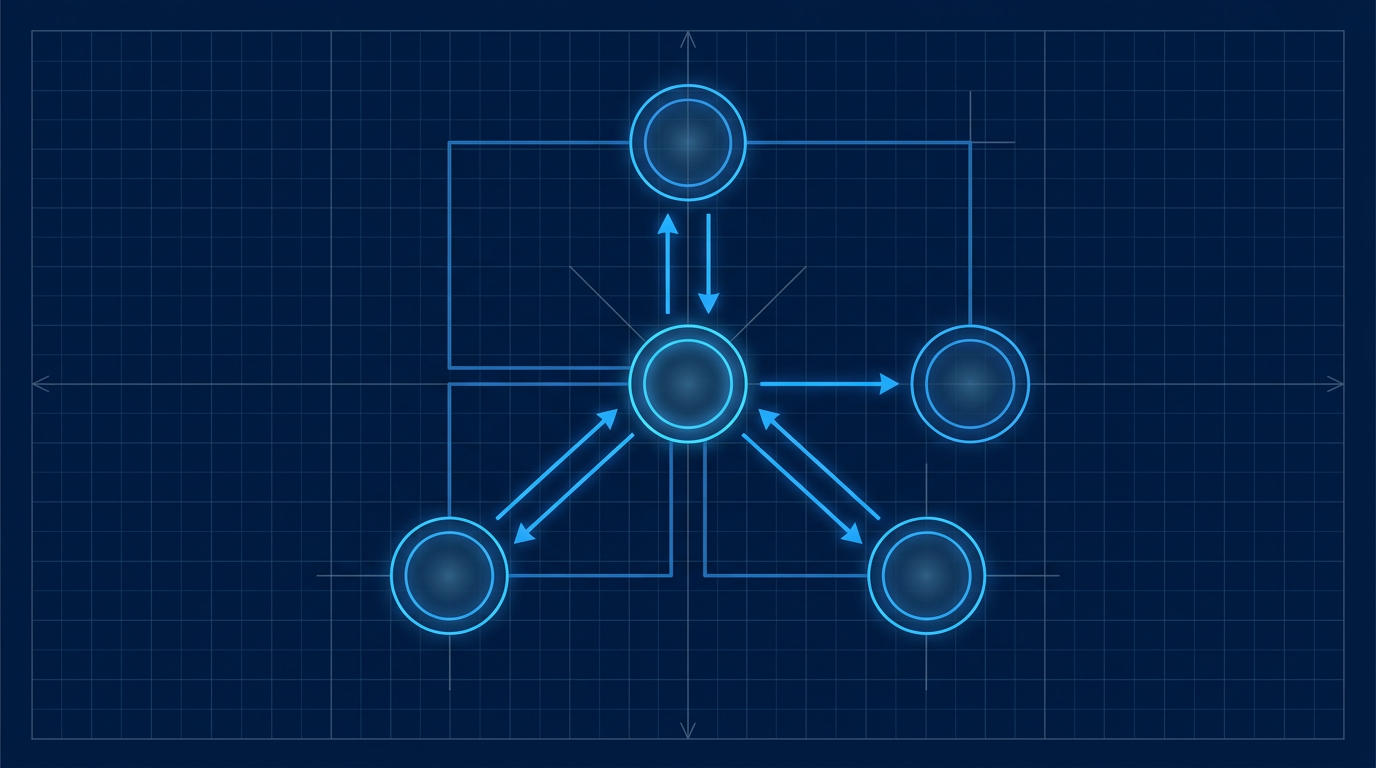
The central trade-off of the integration layer is whether to operate from a single Mission Operations Centre or to distribute control authority across multiple nodes.
A centralised architecture simplifies configuration management, eliminates duplication of command authority, and presents a single authoritative hub for telemetry and commanding. The cost is a single point of failure: if the MOC is unreachable, the mission has no command path. For high-contact-frequency missions, a single MOC can also become a processing bottleneck.
A distributed architecture improves resilience and can reduce latency to geographically dispersed ground stations, but it demands rigorous interface standardisation and data synchronisation. Without both, you risk conflicting command authority or telemetry gaps between nodes. The right choice is governed by the availability requirements and contact frequency you established in Step 1 — there is no universally correct answer.
Single-Site vs. Multi-Site Topology
Your orbit regime drives this decision directly. A LEO spacecraft may be visible to a single ground station for only a few minutes per pass — and depending on inclination, may have as few as three or four passes per day from any one site. A single-site topology cannot provide adequate contact frequency for most LEO missions.
A GEO spacecraft, once on station, is visible continuously from a single site, making single-site topology operationally viable for routine operations. The architecture question for GEO is not whether one site is sufficient for coverage, but whether a second site is warranted for redundancy.
Evaluate your topology choice against these decision axes:
- Contact frequency requirement: How many passes per day does your mission need, and can a single site deliver them given the orbit? LEO constellations and high-inclination orbits almost always require multi-site or third-party ground network access.
- Redundancy and availability target: If your availability requirement from Step 1 is high, a single site with no backup creates unacceptable risk. A second site — even geographically close — provides a recovery path.
- Integration and operations burden: Each additional site multiplies the interface standardisation, network backhaul, and operational coordination work. A three-site network is not three times a one-site network — the integration complexity grows non-linearly.
- Third-party network access as an alternative: Shared commercial ground networks can provide multi-site coverage without the full ownership burden. This trades operational control for deployment speed and contact frequency — a trade-off worth evaluating explicitly against your mission profile.
Once you have resolved the topology, you must define how data moves across it.
Ground Network Data Routing
The routing architecture — how telemetry and command data flows between ground stations, the MOC, the Science Operations Centre, and end users — is an architectural decision, not an IT infrastructure choice. The routing layer determines how quickly commands reach the spacecraft and how reliably telemetry reaches the MOC.
Your options span dedicated leased circuits, IP-based networks, and cloud backhaul. Each carries different consequences for latency, availability, and cost. The DSN ground communications architecture, for example, uses a star network topology with JPL as the hub, supporting both shared IP backbone connections and dedicated circuits to mission operations centres depending on the latency and reliability requirements of each mission. Make this choice against the latency and availability requirements you documented in Step 1 — do not defer it to the network team as an implementation detail.
Cloud backhaul is an increasingly viable routing option for certain mission profiles, but its full architectural implications — virtualisation, elasticity, and ground-segment-as-a-service models — are addressed in Step 4.
Open-Architecture Frameworks: GMSEC and EGS-CC
The integration layer needs a software framework that defines how components exchange data. Choosing this framework before procuring individual components is one of the most consequential decisions in this step.
The framework defines the interface contract that every component must meet. Selecting it early — before vendor procurement — means components are evaluated against a fixed standard, not integrated ad hoc. Selecting it late means bespoke point-to-point integrations accumulate, each one a future maintenance liability.
NASA's GMSEC (Goddard Mission Services Evolution Center) architecture is a well-documented reference example of this principle in practice. GMSEC uses a publish/subscribe message bus and standardised interfaces: components publish messages to a software bus using a standard subject-name and message format, and subscribing components receive only the messages relevant to them. The key architectural value is that the interface contract is with the bus, not with each other — a new component need only conform to the GMSEC message standard to participate in the system, without bespoke integration against every existing component.
ESA's approach at ESOC offers a complementary model at the mission control software layer. SCOS-2000 (Spacecraft Control and Operations System) provided a generic, configurable mission control infrastructure supporting telemetry reception, telecommanding, archiving, and display across multiple missions on shared infrastructure. Its successor, EGS-CC (European Ground Systems — Common Core), extends this with a component-based, service-oriented architecture designed to support both pre-launch integration and validation and post-launch operations, and to be reused across the full range of European mission types. The architectural value of both is standardisation at the mission control layer: a mission team moving from integration and testing to operations works within the same infrastructure, reducing transition risk and integration burden.
COTS vs. Bespoke Infrastructure
Resolve the COTS vs. bespoke trade-off deliberately, against your mission's complexity, operational lifetime, and the depth of engineering support you will need over that lifetime.
COTS-based integration offers faster deployment and lower upfront investment, but introduces vendor dependency. If a vendor discontinues support or the product diverges from your mission's needs, your ability to modify or deeply support the system may be constrained — a significant risk for missions with long operational lifetimes.
Agency-standard or bespoke infrastructure (frameworks like GMSEC or EGS-CC) offers higher control, reduced vendor lock-in, and better long-term supportability for complex missions. The trade is longer development timelines and higher upfront investment. For a mission expecting a decade of operations, the depth of engineering support the chosen infrastructure enables is an architectural consideration, not merely a commercial one.
Step 3
Design the Communication Link Architecture

Key Insights
Link budget sets antenna, power, and coding choices.
FSO sidesteps congested, licensed RF spectrum.
CFLOS is a hard FSO link-closure requirement.
Site diversity needs 300 km separation minimum.
Communication link architecture is not a hardware selection exercise — it is a cascade of design decisions that originates in the mission data volume and timeliness requirements you established in Step 1. The choices you make here (frequency band, link modality, diversity strategy) directly constrain antenna aperture, ground station count, processing architecture, and spectrum licensing obligations.
Frequency Band Selection
Select your frequency band based on mission data volume and link margin requirements, not on convention. The core trade-off is consistent across all bands: available bandwidth scales with frequency, but so do atmospheric attenuation, free-space path loss, and pointing precision requirements.
| Band | Typical Allocation | Atmospheric Sensitivity | Typical Use Case |
|---|---|---|---|
| UHF / S-band | S-band: 2025–2110 MHz uplink / 2200–2300 MHz downlink | Low — good link margins, tolerates weather | TT&C, low-data-rate command and telemetry links |
| X-band | 8025–8400 MHz downlink (Earth Exploration) | Moderate — small weather margin required | Science data downlinks, moderate-throughput missions |
| Ka-band | 25,500–27,000 MHz downlink | High — rain fade and tropospheric scintillation significant | High-throughput missions, NASA's preferred future band |
A comparison table communicates the band-selection decision framework more clearly than prose — the reader can scan across bandwidth, atmospheric sensitivity, and typical use case simultaneously to identify which band fits their mission profile.
Use UHF and S-band for TT&C and low-data-rate links: wide beamwidths, forgiving link margins, and lower ground equipment complexity make them the reliable baseline for command and housekeeping traffic. Earth observation missions operated by ESA have long used S-band for TT&C precisely because propagation loss through the atmosphere remains below 1 dB.
X-band is the established standard for science data downlinks, with the Earth Exploration Satellite allocation spanning 8025–8400 MHz — a bandwidth that suits missions returning hundreds of Mbps. ICESat-2 demonstrated 220 Mbps on X-band downlink, illustrating what the band can support at current ground station apertures.
Ka-band offers roughly four times the bandwidth of X-band and is NASA's preferred direction for future small satellite missions. The trade-off is real: higher atmospheric sensitivity means rain fade and tropospheric scintillation must be budgeted into your link margin, and ground antenna aperture requirements increase accordingly.
Link Budget as an Architectural Input
Close the link budget before finalising any hardware choices. The link budget is not a verification exercise performed after the architecture is set — it is the calculation that determines your architecture. It accounts for free-space path loss, transmit power, antenna gain at both ends, atmospheric attenuation, cable and pointing losses, and system noise temperature, producing a link margin that tells you whether the link closes under worst-case conditions.
A 3 dB link margin is the standard design target for near-Earth satellite links at LEO slant ranges up to approximately 1,500 km. Margins below this risk link closure failure under adverse atmospheric conditions. The link budget outcome determines your antenna aperture, transmit power, and modulation and coding choices — all of which have cascading hardware implications.
The link budget also exposes the frequency duality: lower frequencies suffer less free-space loss over the same range, but the smaller aperture-to-wavelength ratio means antenna gain is harder to achieve without a physically large dish. Higher frequencies achieve more gain from a compact aperture but pay in atmospheric attenuation. Resolving this trade-off is the link budget's job.
RF Spectrum Constraints as an Architectural Driver
Treat spectrum access as an architectural risk, not a regulatory formality. As more missions compete for X-band and Ka-band allocations, the congestion of licensed RF spectrum is becoming a programme-level constraint — one that the link budget cannot fix.
This constraint is one of the structural drivers pushing architectural interest toward higher frequency bands and, ultimately, toward optical links that operate entirely outside the licensed RF spectrum. Free-space optical communication is currently unlicensed — a structural advantage that grows more valuable as RF bands fill.
Free-Space Optical Communication
Optical links at 1550 nm are a live architectural direction, not a future technology. The 1550 nm wavelength has become the standard for satellite FSO links for three converging reasons: it sits at the eye-safe threshold (allowing higher transmitted power than shorter wavelengths such as 1064 nm), it falls within an atmospheric transmission window with low absorption, and it is directly compatible with erbium-doped fibre amplifier (EDFA) technology — the same amplifier class that underpins terrestrial fibre networks.
FSO links operate at carrier frequencies orders of magnitude above Ka-band RF, enabling data rates that RF cannot match within the licensed spectrum. NASA's TBIRD payload demonstrated 200 Gbps on an optical downlink — a figure that illustrates the throughput headroom optical links provide.
The primary architectural challenge for FSO is atmospheric. Clouds cause complete link outage: water clouds can produce attenuation exceeding 100 dB/km, which no link margin can absorb. Your FSO architecture must therefore treat cloud-free line of sight (CFLOS) as a hard link-closure requirement, not a probabilistic nuisance. Atmospheric turbulence introduces beam wander and scintillation — intensity fluctuations that can exceed ±6 dB — which the uplink hardware and coding strategy must be designed to tolerate.
The architectural responses to these challenges are site diversity, adaptive optics, and forward error correction. Adaptive optics at the ground station compensates for turbulence-induced phase errors across the receive aperture, improving coupling efficiency into the detection fibre. Forward error correction and data interleaving provide robustness against short-duration scintillation fades.
Site and Emitter Diversity
Deploy multiple geographically separated optical ground stations to meet your link availability specification. Site diversity works because cloud cover is spatially correlated: two stations separated by at least 300 km will rarely be simultaneously obscured by the same cloud system. Analysis of European OGS networks shows that five stations distributed across Europe can achieve approximately 98% link availability — and an intercontinental network of nine or more stations can reach close to 100% over multi-year observation periods.
The number and separation of sites you need is a function of the CFLOS probability required to meet your mission's availability specification. NASA's optical communications programme estimates approximately 11 stations are needed to achieve greater than 99.9% availability. Make this calculation at the architecture stage — site diversity is a network topology decision, not an operational workaround.
Emitter diversity at a single site — transmitting multiple spatially separated, mutually incoherent beams — provides additional mitigation against beam wander and local atmospheric effects. When uplink beams are separated beyond the atmospheric coherence length, the probability that all beams are simultaneously deflected off-axis is substantially lower than for a single beam. This is a hardware and beam-steering decision that must be specified at the architecture stage.
The Optical Uplink Hardware Layer
An EDFA-based uplink amplifier at the ground station boosts the optical signal to the power levels needed to close the link to the satellite. The amplifier must deliver sufficient average output power — on the order of tens of watts for demanding link budgets — while maintaining the beam quality and modulation fidelity the link requires.
The most architecturally significant capability in this hardware layer is how the tracking beacon and uplink data are handled. Our EDFA for free-space optical communications (developed by Woodrow Scientific Limited) nests the tracking beacon and uplink data in a single amplified beam: the beacon rides at low amplitude and the data above it via amplitude modulation, with three operating modes covering acquisition, tracking, and data transmission. This single-beam approach simplifies the optical train at the ground station and avoids the alignment complexity of separate beacon and data amplifiers — a category distinction worth specifying when evaluating uplink hardware.
End-to-end configurability across both hardware and software is the second architectural virtue to require from your uplink amplifier. WSL designs and builds the amplifier in-house, which means both the physical build and the control layer are configured to the ground station. Hardware configuration covers operating band (C-band, L-band, or dual-band from a single source), output power, emitter count (2- and 4-emitter arrays with multi-station synchronisation for diversity architectures), external optical input for third-party transmitters, and cooling. The software layer — WSL's Modulation-on-Demand — provides software-selectable waveform, frequency, modulation index, and combined beacon and data modulation, switchable to CCSDS or SDA standards at high power across C/L-band.
A software-definable amplifier that can be reconfigured across standards and operating modes without hardware replacement protects the programme investment as standards evolve. This matters because the standards landscape for optical satellite communications is still developing. Suppliers who configure both the hardware and software layers to this depth — rather than offering catalogue-fixed units — provide a fundamentally different level of programme support.
WSL was founded in 2012 and manufactures its amplifiers in-house in the UK on patented technology, with fibre-amplifier expertise rooted in Southampton's Optoelectronics Research Centre — the institution where the EDFA was originally developed. In-house design, build, qualification, and support means direct engineering capability: when a programme needs a configuration change or faces a technical issue, the response comes from the engineers who built the hardware, not from an intermediary. The amplifier carries CE and UKCA certification.
Hybrid RF/Optical Architectures
For missions where link availability requirements exceed what a pure FSO architecture can deliver — even with site diversity — a hybrid RF/optical architecture is the appropriate design response. This is not a fallback position; it is a deliberate design choice that exploits the complementary strengths of both modalities.
RF links (typically S-band or X-band) are largely unaffected by the cloud cover that interrupts optical links. An RF link can maintain critical TT&C and latency-sensitive traffic during FSO outages, while the optical link handles high-volume data throughput when CFLOS is available. NASA's LCRD programme combined optical links at 1.244 Gbps with a Ka-band RF backup at 622 Mbps downlink, explicitly to allow each modality to cover the other's constraints.
Choose a hybrid architecture when your mission has both high-throughput data requirements and a link availability specification that site diversity alone cannot meet within your ground station count budget. Choose a pure FSO architecture when the throughput requirement is paramount, the availability specification can be met through site diversity, and the additional RF hardware and spectrum licensing overhead is not justified. Document the design criteria for this choice explicitly — it determines your ground station hardware, network topology, and spectrum licensing obligations simultaneously.
Step 4
Choose Between Software-Defined, Virtualised, and Cloud-Native Architectures
Key Insights
Paradigm choice governs scalability — decide before procuring.
Cloud-native is LEO default; latency drives exceptions.
Hybrid: cloud for data, dedicated for command.
The decision you face in this step is not a hardware procurement choice — it is a paradigm-level architectural commitment that determines how your ground segment scales, adapts to evolving mission requirements, and integrates with future payloads and operators.
Treat it with the same rigour you applied to topology decisions in Step 2: the wrong paradigm for your mission is costly to reverse, and the right one is a force multiplier across the programme lifecycle.
Software-Defined Radio: The First Step Away from Fixed Hardware
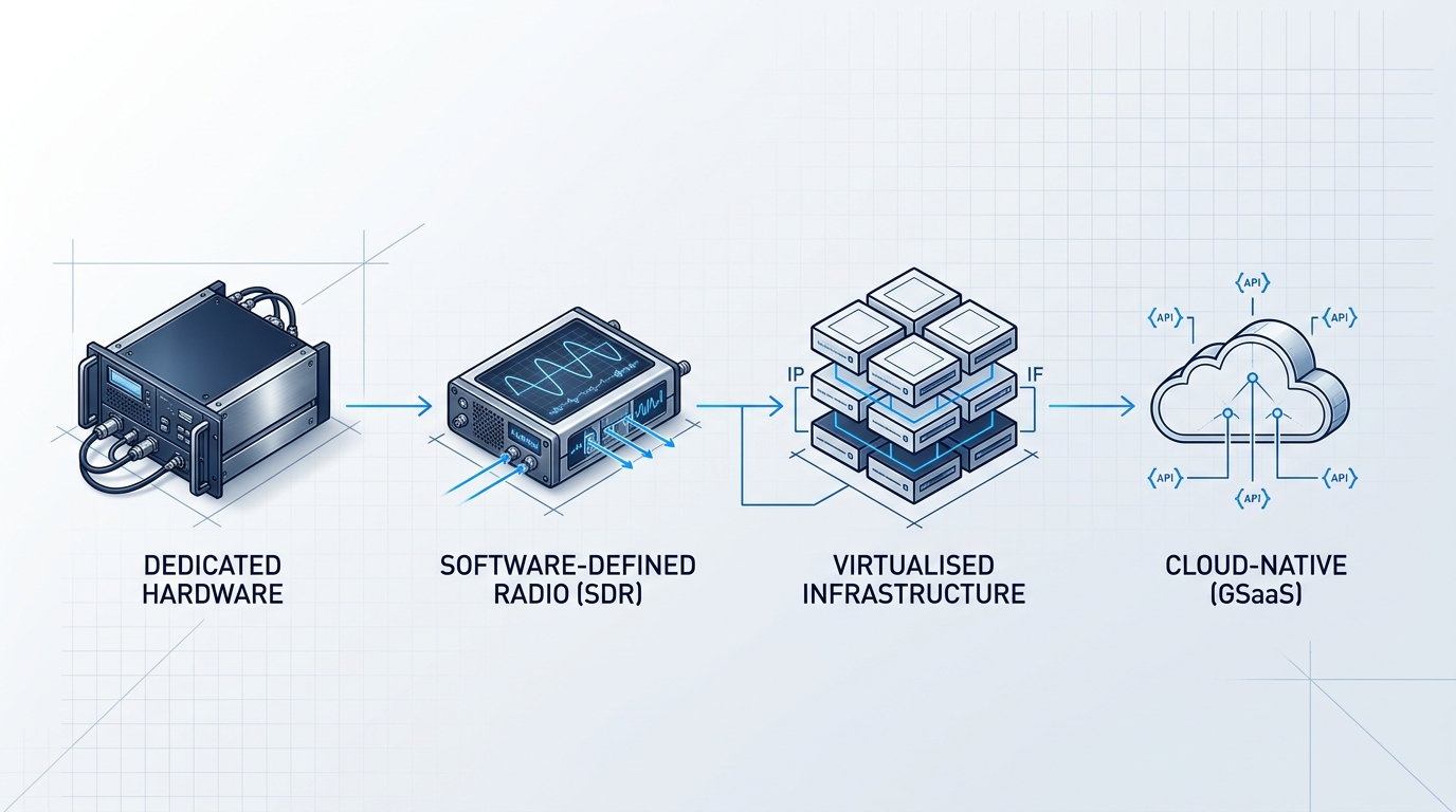
Software-defined radio (SDR) replaces fixed-function modems with software-reconfigurable signal processing, allowing the same physical hardware to support multiple modulation schemes, frequency bands, and protocol stacks through software updates rather than hardware replacement.
ESA's SDR TT&C modem programme and the Kratos fully software-defined hub are concrete examples of this direction being pursued at programme level — both demonstrate that SDR is an operational architectural direction, not a research concept.
The design trade-off is real: SDR introduces some processing overhead and latency compared to dedicated hardware, but it gains flexibility and upgradability that no fixed-function modem can match across a multi-year mission.
Virtualised Ground Segment Architecture
Virtualisation at the ground segment level means decoupling software functions from specialised hardware by digitising the intermediate frequency (IF) signal at the antenna and transporting it over IP networks for processing in software, running on cloud compute or commercial off-the-shelf servers.
The VITA-49/DigIF standard (the Digital IF standard) is the mechanism that makes this transport viable — it defines how digitised RF is carried over IP, enabling vendor-agnostic integration between antenna hardware and software-defined processing stacks.
Virtualisation enables hardware consolidation, remote processing, and scalable compute allocation across missions — but it also constrains your design in specific ways.
- High-bandwidth backhaul required: Transporting digitised IF over IP demands robust, high-capacity network links between the antenna and the processing layer; insufficient backhaul becomes the binding constraint.
- Processing latency introduced: Moving signal processing off dedicated hardware and into software on general-purpose compute adds latency at each stage of the chain — quantify this against your mission's timing requirements before committing.
- IP transport security: The IP transport layer carrying digitised RF is an expanded attack surface; security architecture around this layer must be designed in from the outset, not added later.
The standards implications of virtualised architecture — including its relationship to the DIFI standard — are addressed in Step 5.
Cloud-Native Ground Segment and GSaaS
Ground Segment as a Service (GSaaS) is the fully cloud-native model: providers operate globally distributed antenna networks connected to cloud compute platforms, offering pay-per-use access via APIs, with contact scheduling, data downlink, and processed data delivery all handled through software interfaces.
AWS Ground Station and Azure Orbital are operational examples of this model — both offer API-driven contact scheduling and direct delivery of satellite data to cloud storage, eliminating the need to operate your own antenna infrastructure.
The architectural implications for your ground segment design are significant.
- No upfront capital expenditure on antenna infrastructure: The provider operates the ground stations; your programme pays per contact pass, shifting cost from capex to opex.
- Elastic scaling of compute and contact capacity: Compute resources and contact scheduling scale with demand rather than being sized to a fixed peak — useful for missions with variable downlink cadence.
- API-driven contact scheduling: Contacts are scheduled and managed programmatically, and processed data is delivered directly to cloud storage, reducing the operational overhead of ground station management.
- Reduced time to first contact: New missions can achieve first contact within days of launch rather than months, using an existing global antenna network.
Weigh these benefits against four design constraints that your requirements matrix must directly address.
- Data sovereignty: Your mission data is processed and stored within the provider's cloud infrastructure — understand which jurisdictions govern access and whether that is compatible with your programme's classification and export control requirements.
- Latency to command: Routing commands through remote cloud infrastructure adds latency; for time-critical operations or anomaly response, this may be unacceptable — particularly for LEO missions where contact windows are short.
- Vendor lock-in: Dependency on a single GSaaS provider's API and coverage network creates programme risk if the provider changes pricing, coverage, or API contracts.
- Coverage gaps: No single commercial GSaaS network has universal coverage; map the provider's ground station locations against your orbit and contact frequency requirements before selecting a provider.
The GSaaS market is not a niche option — the global market was valued at approximately $3.8 billion in 2025 and is projected to reach approximately $14.6 billion by 2034, with cloud-based deployments accounting for approximately 67.3% of revenue in 2025.
Read this as a signal: cloud-native is now the default architectural direction for new LEO missions, and your programme's starting assumption should be GSaaS unless specific requirements rule it out.
Routing command uplink through remote cloud infrastructure introduces latency that can be unacceptable for LEO missions — where contact windows last only minutes and anomaly response time is critical. If your mission requires guaranteed command-response times, do not assume a fully cloud-native command path is adequate. A hybrid architecture — cloud for data downlink and processing, dedicated or sovereign infrastructure for command uplink — is often the correct design response to this constraint.
Evaluate your mission's latency tolerance explicitly before committing to a fully cloud-native command path, and design the command uplink separately from the data downlink if the two carry different latency and authority requirements.
Containerised Ground Software Architecture
Containerised, microservices-based ground software is the software-layer counterpart to hardware virtualisation — it is distinct from SDR (which addresses the signal processing layer) and from GSaaS (which addresses the infrastructure layer).
Architecting your ground software stack as modular, containerised components — orchestrated via tools such as Kubernetes — enables rapid deployment of new mission capabilities, reuse of software modules across missions, and compute scaling without hardware changes.
Frame containerised ground software as a design philosophy that complements virtualised and cloud-native infrastructure: it is the approach that makes your software stack as adaptable as your infrastructure.
When Dedicated Infrastructure Is the Correct Choice
Dedicated, non-virtualised, non-cloud infrastructure is not a legacy preference — it is the correct architectural choice for specific mission profiles, and your requirements matrix should lead you there if any of the following conditions apply.
| Paradigm | Capex | Flexibility | Latency Profile | Sovereignty Control |
|---|---|---|---|---|
| Dedicated hardware | High — own infrastructure | Low — fixed-function, hardware changes required | Lowest — processing co-located with antenna | Full — data never leaves your infrastructure |
| Software-defined (SDR) | Moderate — COTS hardware, software licences | High — reconfigurable via software updates | Low — some overhead vs dedicated | Full — processing remains on your hardware |
| Virtualised (DigIF/IP) | Moderate — COTS servers, backhaul costs | High — scalable compute, vendor-agnostic | Moderate — IP transport and software processing add latency | Configurable — depends on where compute is hosted |
| Cloud-native (GSaaS) | Low capex — pay-per-use opex model | Very high — elastic compute and contact capacity | Higher — remote infrastructure adds command latency | Limited — governed by provider jurisdiction and contracts |
Provides a grounded, side-by-side view of the four architectural paradigms across the decision-relevant axes — capex, flexibility, latency profile, and sovereignty control — enabling the reader to map their mission requirements directly to the appropriate paradigm.
If your mission carries classified payloads, operates under strict data sovereignty or command authority requirements, demands guaranteed command-response times, or has a contact frequency high enough that pay-per-use costs exceed dedicated capacity costs — dedicated infrastructure is the analytically correct outcome.
The goal of this step is not to arrive at cloud-native; it is to arrive at the paradigm your mission requirements support, with the trade-offs understood and documented.
Step 5
Apply Standards and Interoperability Decisions
Key Insights
Standards are architectural decisions — choose them deliberately.
DIFI decouples RF hardware from software processing.
CCSDS for civil; SDA OCT/NEBULA for defence optical.
Hardware lock-in creates long-term integration debt.
Standards selection is not a procurement task — it is an architectural decision made at design time, with consequences that compound over the system's operational life. The standards your ground system commits to at this stage determine which networks it can interoperate with, which vendors can supply interchangeable components, and how much integration work accumulates when those standards evolve.
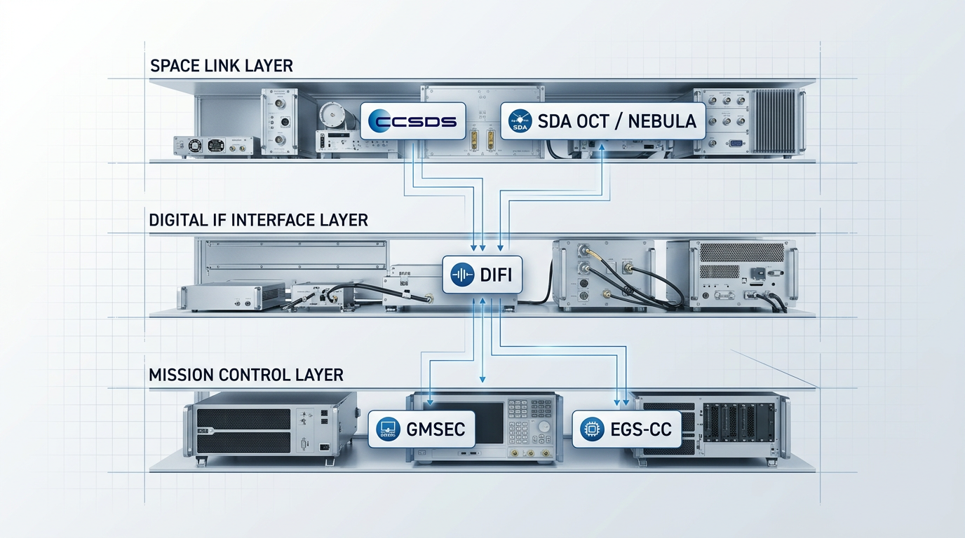
Standards decisions apply at three distinct layers of the ground segment stack: the space link layer (governing spacecraft-to-ground RF and optical protocols), the digital IF interface layer (governing the handoff between RF hardware and software-defined processing), and the mission control layer (governing how ground system components communicate with each other). Each layer has its own standards framework, and choices at each layer are largely independent.
The three primary frameworks that govern these layers are CCSDS, SDA OCT/NEBULA, and DIFI — each addressing a different architectural boundary within the ground segment.
- CCSDS (Space Link Services and SLE): The Consultative Committee for Space Data Systems defines the foundational interoperability standard for civil and scientific missions. Its Space Link Services (SLS) area specifies RF modulation, channel coding, and data link protocols. Its Space Link Extension (SLE) services enable cross-support between agencies — a spacecraft operated by one agency can be serviced by another agency's ground station without bespoke equipment at the foreign site. For any civil or scientific mission, CCSDS compliance is an interoperability enabler: it opens access to a global network of compatible ground stations rather than constraining the architecture to proprietary infrastructure.
- SDA OCT and NEBULA (Defence Optical Links): The Space Development Agency's open Optical Communications Terminal standard is a design requirement for the Proliferated Warfighter Space Architecture (PWSA). Its architectural intent is vendor interoperability: terminals from different manufacturers must conform to the same OCT specification so they can exchange data across the network without bespoke integration. NEBULA is the network-layer complement to OCT, defining how optical links are managed and routed across the transport layer. Both standards are still maturing, which has direct implications for how you design for standards evolution — covered below.
- DIFI (Digital IF Interoperability): The Digital Intermediate Frequency Interoperability standard governs the digital interface between RF front-end equipment and software-defined signal processing. By standardising the IF-to-digital handoff, DIFI decouples the antenna and RF chain from the processing layer — components from different vendors can be connected without bespoke integration work. This is the standards-layer expression of the software-defined paradigm introduced in Step 4: DIFI makes vendor-agnostic ground segment integration practical rather than aspirational.
The standards landscape across all three layers is still evolving. SDA OCT and NEBULA are explicitly under active development; CCSDS Blue Books are periodically revised; and proprietary protocols continue to compete with open standards at the digital IF layer.
An architect who commits to a single standard at the hardware level carries forward integration debt: when the standard changes or a second standard must be supported, hardware must be replaced rather than reconfigured. The architectural response is to treat protocol compatibility as a system-level property — design for standards flexibility using software-definable hardware that can switch between standards (such as CCSDS and SDA) without physical replacement. The same logic that justifies virtualisation in the software layer applies here.
At the mission control layer, the equivalent of CCSDS and DIFI is a choice between open-architecture integration frameworks. GMSEC (Goddard Mission Services Evolution Center) provides a publish/subscribe message bus with standardised interfaces, allowing ground system components — displays, planning tools, telemetry processors — to be swapped out independently without rebuilding the integration layer. EGS-CC (ESA's European Ground Systems — Common Core) takes a component-based, service-oriented approach to the same problem. Committing to one of these frameworks early substantially reduces integration risk: the framework becomes the stable contract between components, not the components themselves.
For defence missions, a specific trade-off applies at this step. Standards compliance — particularly CCSDS — enables cross-support and access to shared ground networks, reducing cost and increasing coverage. But sovereignty and security requirements may constrain which standards and which networks a classified mission can use: a programme that adopts CCSDS for interoperability may not be able to route classified command authority through a foreign agency's ground station, even one that is technically compatible. Think carefully about which standards apply to which functional layers, and which layers carry security-sensitive traffic — the answer shapes not just the interoperability architecture, but the security architecture that follows in Step 6.
Step 6
Design for cybersecurity and resilience from the outset
Key Insights
Design security in from concept, not retrofit.
Segment TT&C from payload and external networks.
Apply zero-trust at every ground segment interface.
Route sensitive commands only through sovereign nodes.
Security and resilience are not layers you apply to a finished satellite ground system — they are properties you engineer in from the concept phase. Retrofitting security onto a completed architecture is significantly more expensive and structurally less effective than specifying it at the outset; the systems security engineering literature is consistent on this point, and the practical consequence is that decisions deferred to integration or operations are decisions that cannot be fully recovered.
Before designing your mitigations, orient the architecture to the threat landscape it must resist. Ground segment threat categories that your architecture must address include:
- Command intrusion and payload control: Unauthorised commands reaching the spacecraft via a compromised or spoofed uplink path.
- Malware propagation: Malicious code spreading laterally across ground segment networks from an initial point of compromise.
- Hijacking of command authority: Credential theft or session hijacking that transfers legitimate command authority to an adversary.
- RF interference and jamming: Deliberate disruption of uplink or downlink signals, degrading or denying communications.
- Physical threats to ground infrastructure: Direct action against antenna sites, operations centres, or network interconnects.
Design the command uplink with authenticated encryption specified at the architecture stage, not deferred to integration. The primary structural protection against command injection is end-to-end authentication between the command generation point and the spacecraft — this must appear in the interface definition, not in a configuration document written after procurement.
Specify anti-replay protections — command sequence counters and nonces — as architectural requirements, alongside carrier lockup and an out-of-band backup command path. These are not operational configurations; if they are absent from the architecture when interface definitions are locked, adding them cleanly later is extremely difficult.
Return to the topology decisions from Step 2 and treat network segmentation as a structural security property of that topology. The TT&C network, payload data network, mission planning systems, and external-facing interfaces must be separated at the architecture stage — separation specified in the topology design is enforceable; separation applied post-deployment through firewall rules alone is structurally porous and limits your ability to contain lateral movement after a compromise.
At the MOC-to-ground-station and MOC-to-user interfaces, build in the assumption of a hostile environment: verify all communications regardless of network location and enforce least-privilege access per session. This verify-first posture must be specified in the interface design — if it is left to a security team to configure after integration, the architecture has already made it optional rather than structural.
The site diversity topology established in Step 2, and the diversity architecture introduced for FSO links in Step 3, serve a dual function here. Multiple geographically separated ground stations protect against atmospheric outages and against physical threats to a single site; emitter diversity at a single site provides resilience against deliberate interference targeting a specific antenna.
These are topology decisions with a security dimension — they cannot be meaningfully added after the architecture is set. Frame them at design time as resilience mechanisms against physical threats and deliberate jamming, not only as link-availability mitigations.
For defence missions using the commercial ground networks introduced in Step 4, sovereignty is an architectural risk that must be addressed before procurement. Host-nation laws can interrupt access to commercial antennas on foreign soil, so the architecture should specify which command paths are permitted to traverse commercial infrastructure and which must be routed exclusively through sovereign nodes — with high-sensitivity commands reserved for the latter.
Qualify your component suppliers as an architectural input, not a procurement afterthought. Components sourced through resellers or importers without in-house engineering capability carry higher integration risk and slower resolution of operational issues than those procured directly from manufacturers with dedicated engineering support — the depth of supplier engineering access is a system-level risk factor that belongs in the architecture phase alongside topology and interface decisions.
When this step is complete, your ground system architecture is requirements-driven, standards-flexible, and resilient by design: the command uplink is authenticated, the network is segmented by function, every interface operates on a verify-first basis, diversity nodes protect against physical and RF threats, sovereign routing is specified for sensitive commands, and supplier risk is qualified before procurement begins.
Conclusion
From requirements to resilience: completing your ground system architecture
A satellite ground system architecture designed through this sequence is requirements-driven rather than component-led, modular rather than monolithic, and resilient by design rather than by retrofit — qualities that compound in value as the mission evolves.
The principle worth carrying forward is simple: early decisions constrain later options, and working through the sequence deliberately surfaces trade-offs before they become costly commitments.
The work ahead — procurement, integration testing, operations concept development, and standards monitoring — sits on firmer ground when the architecture beneath it was built this way.
Satellite ground system architecture: frequently asked questions
Practical answers to the questions engineers, programme managers, and mission architects most often ask about satellite ground system design — covering cost, LEO vs GEO trade-offs, hybrid RF/optical integration, GSaaS decisions, standards selection, and resilience architecture.
A dedicated, fully equipped ground station is a multi-million-dollar capital commitment — industry estimates place traditional ground segment capital costs at $10 million to over $100 million depending on mission complexity and number of sites. The range is too wide for a single figure to be useful, because the drivers vary enormously. Frequency band matters: Ka-band infrastructure costs significantly more than UHF or S-band. Antenna size matters: a high-throughput science downlink station requires a much larger dish than a TT&C-only node. Orbit matters: LEO stations need fast-tracking antennas, while GEO stations can use fixed-pointing dishes. Ground Segment as a Service (GSaaS) changes the equation entirely. By treating antenna time as a cloud resource billed per minute or per contact, GSaaS converts the capital commitment to operational expenditure with no upfront infrastructure cost. For a LEO mission with moderate contact requirements, pay-per-use access to a globally distributed antenna network is typically far more economical than building dedicated infrastructure — and it is available immediately.
The fundamental difference is contact time. A LEO satellite passes over any given ground station for only a few minutes per orbit before dropping below the horizon. A single-site ground station is therefore architecturally insufficient for continuous coverage or high-contact-frequency LEO missions. GEO satellites appear stationary from the ground, so a small number of fixed sites can achieve near-continuous coverage with no tracking required. LEO missions must compensate with either a distributed multi-site ground network or GSaaS access to a globally distributed antenna pool — typically 10 to 30 or more sites — that collectively provide adequate contact frequency across the satellite's ground track. LEO constellations are the primary driver behind the shift toward cloud-native and virtualised ground segments. The operational tempo involved — scheduling dozens of passes per day across multiple sites and satellites — makes manual, site-by-site contact management impractical. Automated, API-driven scheduling and cloud-based data routing become architectural necessities rather than optional upgrades.
Yes — hybrid RF/optical architectures are a practical and increasingly well-understood integration path, supported by NASA research into switching strategies between RF and free-space optical (FSO) channels. The existing RF chain continues to handle TT&C, command uplink, and fallback data links. The optical layer adds high-throughput downlink and uplink capacity that RF cannot match without spectrum licensing. The two chains operate in parallel, with the system switching between or combining them based on atmospheric conditions: RF typically suffers under rain while FSO is vulnerable to fog and cloud, so the two modalities are naturally complementary. The critical integration point is the interface between the optical terminal hardware and existing mission control infrastructure. Software-definable optical uplink hardware that supports both CCSDS and SDA standards at the physical layer simplifies this considerably — it presents a standards-compatible interface to existing ground software, eliminating the need to replace or extensively modify the mission control stack. Hardware with end-to-end configurability, including switchable CCSDS/SDA compliance at full power output, provides the additional benefit of standards future-proofing: if the mission's operational domain shifts or standards evolve, the hardware adapts without replacement.
GSaaS is the default architectural choice for new LEO missions. It eliminates upfront capital commitment, provides immediate access to a globally distributed antenna network, and scales elastically with mission contact requirements — with no infrastructure to procure, site, or staff. Dedicated infrastructure is justified in three specific circumstances. First, when the mission carries classified payloads requiring sovereign command authority and physical access control — commercial cloud routing is incompatible with some classification requirements. Second, when there is a strict guaranteed-latency requirement for command response that commercial cloud network routing cannot reliably satisfy. Third, when contact frequency is high enough that dedicated capacity becomes more economical than pay-per-use rates over the mission lifetime; the break-even point depends on orbit, data volume, and provider pricing. A hybrid model — GSaaS for data downlink combined with a dedicated sovereign node for command uplink — is a valid architectural middle ground for missions with mixed sensitivity requirements. It captures the cost and coverage advantages of GSaaS for the bulk data path while preserving sovereign control over the command channel.
CCSDS (Consultative Committee for Space Data Systems) is the long-established multi-agency standard for civil and scientific missions. It covers RF and optical modulation, channel coding, data link protocols, and the Space Link Extension (SLE) services — which allow agencies to share ground station infrastructure across missions without agency-specific equipment at foreign sites. If your mission is civil or scientific and may need cross-support from partner agencies, CCSDS is the correct design target. SDA OCT and NEBULA are the emerging framework for optical inter-satellite and space-to-ground links in defence architectures, designed specifically for the Proliferated Warfighter Space Architecture (PWSA). The SDA OCT Standard defines interoperability specifications for optical communications terminals across space-to-space, space-to-ground, space-to-air, and space-to-maritime links. NEBULA defines the networking layer above those links. If your mission is a defence optical programme, SDA is the correct design target. For missions that may need to operate across both domains — or that must remain compatible as both frameworks continue to evolve — the practical answer is to design for hardware-level standards flexibility: hardware that can switch between CCSDS and SDA compliance without replacement is the architectural hedge against standards evolution risk.
Resilience must be designed in at the architecture stage — it cannot be added operationally to a completed system. The primary structural mitigation is multi-site network topology: geographically distributed ground stations eliminate single-site dependency and increase LEO contact opportunities simultaneously. Redundant command paths — multiple independent routes from the Mission Operations Centre to the spacecraft — ensure a single network failure cannot interrupt command authority. Network segmentation is the key cyber-resilience measure: isolating the TT&C network from data-processing and external-facing segments limits blast radius if a compromise occurs, preventing lateral movement between segments. NIST IR 8401 specifically identifies network segmentation as a ground segment cybersecurity control. For optical links, site diversity (geographically separated optical ground stations) and emitter diversity (multiple apertures at a single site) reduce the probability of simultaneous cloud obscuration to acceptable levels. The CISA NSTAC STF Report confirms that satellite operators use redundant, geographically diverse facilities connected by path-diverse, cryptographically secured links as standard practice. Backup facilities not co-located with the primary MOC close the remaining gap — ensuring that a single physical event, whether natural or deliberate, cannot simultaneously disable both the primary and backup ground infrastructure.