

Introduction
If you work in the space sector — as an engineer, a mission planner, a researcher, or someone making infrastructure decisions — you already know that the spacecraft is only part of the story.
This guide is written for people who want to understand the ground segment properly: how it is built, how it operates, what shapes the decisions around it, and where it is heading.
The sections that follow build on each other deliberately, moving from foundations through to the operational and commercial realities that anyone running a ground station eventually confronts.
TL;DR
The ground segment is far more operationally demanding and strategically consequential than it is usually given credit for — and it is changing fast. Optical links, software-defined architectures, and commercial network models are rewriting the rules, even as spectrum congestion and contact-window physics remain hard constraints every operator must plan around.
This article covers:

Ground station components and signal chain
Frequency bands and regulatory licensing
Types of ground stations and coverage logic
TT&C and mission operations
Operational challenges: contact windows, scheduling, cost
Ground Station as a Service and optical links
What is a Satellite Ground Station?
Every satellite mission produces a photograph, a measurement, a command response, or a piece of science — but none of that value reaches anyone without the infrastructure on the ground that makes the exchange possible. The spacecraft gets the attention; the satellite ground station is what makes the mission work.
A satellite ground station — also referred to as an Earth station, with both terms used interchangeably across the industry — is a terrestrial radio facility equipped with antennas and associated systems used to communicate with, track, and control satellites, and to receive or transmit data between space and Earth.
Where the Ground Station Fits: The Three-Segment Model
Space systems are conventionally described through a three-segment architecture: the space segment, the ground segment, and the user segment.
| Segment | What it comprises | Role in the mission |
|---|---|---|
| Space segment | The satellite or constellation of spacecraft | Collects, generates, or relays mission data; receives and executes commands |
| Ground segment | Ground stations, networks, control centres, and data distribution infrastructure | Receives data from the spacecraft, sends commands, and routes information onward |
| User segment | Scientists, operators, end-users, and their receiving terminals | Consumes the mission's data or services delivered by the ground segment |
The three-segment model of a satellite mission, as described in NASA's State of the Art: Ground Data Systems series.
A point worth emphasising: the ground segment is not just the antenna. As NASA's Ground Data Systems documentation makes clear, it encompasses ground stations, the networks connecting them, control centres managing spacecraft operations, and the remote terminals through which users retrieve processed information.
The Four Primary Functions of a Ground Station
Within that broader ground segment, the ground station itself serves as the telemetry, tracking, and command interface with the spacecraft — the physical point where the radio link between Earth and orbit is established.
- Telemetry reception: Receiving spacecraft health and status data transmitted down from the satellite, allowing operators to monitor its condition.
- Telecommand uplink: Transmitting operator instructions up to the spacecraft — directing its attitude, payload, and onboard systems.
- Tracking and ranging: Determining the satellite's position, velocity, and trajectory to keep the antenna pointed accurately and support orbit determination.
- Data downlink and distribution: Receiving mission payload data from the spacecraft and routing it onward to the Mission Operations Centre or Science Operations Centre.
These four functions are the vocabulary that runs through every aspect of ground station design and operation — they will be examined in detail in later sections of this guide, but establishing them here as named concepts is essential context for everything that follows.
Direct-to-Earth vs. Space Relay Architectures
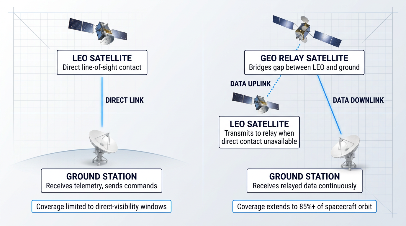
Not all ground stations communicate with the spacecraft directly. Direct-to-Earth (DTE) ground stations provide line-of-sight, point-to-point contact with the satellite — the default approach for the majority of missions.
Where a satellite's orbit makes direct ground contact infrequent or impossible, space relay networks introduce an intermediate satellite to bridge the gap. NASA's Tracking and Data Relay Satellite System (TDRSS), for example, uses relay satellites in geosynchronous orbit to collect data from low-Earth-orbit spacecraft and forward it to ground stations — enabling coverage across more than 85% of a spacecraft's orbit rather than only during brief direct-visibility windows.
Space relay services are most valuable for missions requiring continuous coverage, low latency, or reliable contact during critical events such as launch and early orbit — scenarios where the intermittent nature of DTE contact is a constraint.
The Scale and Diversity of Ground Stations
"Ground station" is a broad category, not a single type of facility. The term covers an enormous range of infrastructure.
At one end of the spectrum sit large deep-space antenna complexes: NASA's Deep Space Network, for instance, operates 70-metre diameter dish antennas at three globally distributed sites, capable of tracking spacecraft tens of billions of miles from Earth. At the other end, compact LEO tracking stations can fit within a small building or even a rooftop installation, using a single steerable antenna to contact a satellite during its brief pass overhead.
Some ground stations are purpose-built for a single mission; others are shared commercial facilities serving dozens of operators across multiple spacecraft. This diversity reflects the enormous range of orbit types, data volume requirements, and mission objectives that ground station infrastructure must accommodate.
The MOC, the SOC, and the Ground Station's Role
Ground stations do not operate in isolation — they are nodes in a larger control infrastructure anchored by two key facilities.
The Mission Operations Centre (MOC) is where all satellite commanding is generated, ground station control is managed, and telemetry is monitored and archived. As described in NASA's ground systems architecture documentation, the MOC is responsible for all communication to and from the spacecraft — the ground station is the physical channel through which those communications flow.
The Science Operations Centre (SOC) handles the scientific dimension: generating and disseminating science data products, planning observations, and determining science operations to be relayed to the MOC for uplink. ESA's ground segment documentation reflects the same division — the operations control centre and science operations centre each depend on the ground station network as their interface to the spacecraft.
Ground stations, in this framing, are not the command centre — they are the essential physical link that makes command and data exchange between the MOC, SOC, and the spacecraft possible at all.
As NASA's State of the Art: Ground Data Systems series states directly: the ground system is responsible for collecting and distributing the most valuable asset of the mission — the data. Without a functioning ground segment, the satellite cannot be commanded, its health cannot be monitored, and its payload data cannot be recovered.
Understanding what a satellite ground station is — and what it does — is the conceptual foundation this guide builds on. The natural next question is how it does it: the antennas, signal chain, and software systems that make up the physical ground station stack are examined in the following section.
Core Components: Antennas, Signal Chain, and Processing
The most visible thing about any satellite ground station is the dish. But the dish is only the beginning — what makes a ground station work is the integrated chain of hardware and software that runs from the antenna's surface all the way to the Mission Operations Centre, converting faint electromagnetic waves into usable digital data and back again.
NASA uses parabolic reflector antennas as the standard for RF ground satellite communications, and their size is never arbitrary. According to the NASA State of the Art: Ground Data Systems report, the gain of a dish reflector is frequency-dependent and directly proportional to the square of its diameter — meaning a larger dish captures more signal energy, and a larger aperture is the primary lever for achieving the gain a mission requires. Dish sizes span an enormous range as a result: from 1 metre for some small satellite LEO stations up to 70 metres for deep-space facilities such as NASA's Deep Space Network.
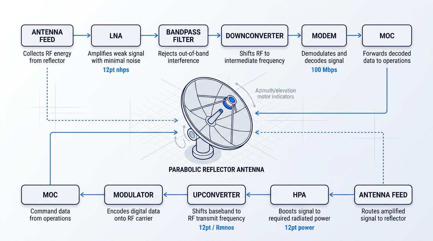
At the focal point of the reflector sits the feed — typically a horn antenna with a circular aperture. The feed collects the RF energy that the reflector has concentrated and routes it into the receive chain. Critically, the feed assembly also houses the LNA (low-noise amplifier) and mechanical bandpass filters.
The reason the LNA lives at the feed, rather than in the equipment room, is a fundamental principle of receiver design: the first active stage in a receive chain sets the noise floor for everything that follows. Any cable run between the antenna and the amplifier introduces loss, and loss adds noise. By placing the LNA as close to the feed as possible — before any lossy cable — the system preserves the signal's integrity right from the point of collection, where it is at its weakest.
The Receive Chain: From Satellite Signal to Digital Data
Once the feed has collected the RF energy, the signal passes through a carefully ordered chain of processing stages, each with a specific job to do.
- LNA: Amplifies the vanishingly weak received signal with minimal added noise, establishing the noise floor for the entire receive chain.
- Bandpass filter: Rejects out-of-band interference and unwanted signals, passing only the frequency range of interest to the next stage.
- Downconverter: Shifts the RF carrier frequency down to an intermediate frequency or baseband, making the signal tractable for digital processing hardware.
- Modem / radio: Demodulates and decodes the signal, converting the RF waveform into a stream of digital data packets or frames.
- Digital data to the MOC: The decoded data is forwarded over the ground network to the Mission Operations Centre for telemetry processing and archiving.
The engineering logic of this chain is about preservation under constraint. The signal arriving from orbit is extraordinarily weak — the ground station's job on the receive side is to amplify, clean, and convert it without degrading what is there. Every stage is designed to add as little noise and distortion as possible, which is why the sequence runs in this order: amplify first, filter second, convert third.
The Transmit Chain: Uplink to the Satellite
The uplink path runs in the reverse direction, presenting a fundamentally different engineering challenge: not preservation of a weak signal, but generation of enough power to close the link over the distance to the satellite.
- Modulator: Takes digital command data from the MOC and encodes it onto an RF carrier waveform using the appropriate modulation scheme.
- Upconverter: Shifts the modulated baseband or intermediate-frequency signal up to the RF transmit frequency used on the satellite link.
- HPA: The high-power amplifier boosts the signal to the power level required to reach the satellite and close the uplink budget.
- Antenna feed: Routes the amplified RF signal to the feed horn, which radiates it via the parabolic reflector as a focused beam towards the satellite.
The HPA (high-power amplifier) is the defining element of the transmit chain, in the same way the LNA defines the receive chain. Where the receive challenge is amplifying a signal without adding noise, the transmit challenge is generating sufficient radiated power — the HPA must drive the signal to a level that survives the path loss over thousands of kilometres and still arrives at the spacecraft with enough margin to be detected.
At the heart of both chains sits the modem, the element that bridges the digital and RF domains. On the receive side it demodulates and decodes; on the transmit side it modulates and encodes. The modem converts between the world of packets, frames, and command sequences and the world of modulated waveforms — it is the translation layer the entire system depends on.
An increasingly common implementation of the modem function is the SDR (software-defined radio). As described in the NASA SOA Ground Data Systems report, an SDR implements receiver and transmitter functions in software running on programmable hardware — typically FPGAs or GPUs — rather than fixed analogue circuitry. The waveform, modulation scheme, and protocol can all be reconfigured by updating the software, without any change to the physical hardware.
A software-defined radio can be updated to support a new satellite, a different waveform standard, or an evolved protocol without hardware changes. For ground stations serving multiple missions or adapting to new standards over time, this is a significant capability advantage over fixed-function modem hardware.
Because a directional antenna must remain pointed at the satellite throughout the contact window as it moves across the sky, every ground station requires a tracking system. This consists of azimuth (horizontal) and elevation (vertical) drive motors, controlled by tracking software that computes where the satellite will be at each moment during the pass.
That computation relies on TLE sets — Two-Line Element sets — which are mathematical representations of a satellite's orbital parameters. Combined with accurate GPS time, the TLE allows the tracking software to generate motor commands as a function of time, actively steering the antenna along the satellite's predicted trajectory.
Two modes govern how the antenna follows the satellite. In program track mode, the antenna follows a pre-computed trajectory derived entirely from TLE predictions — this is the default operating mode. In auto-track mode, the antenna continuously adjusts its pointing based on the strength of the received signal, actively seeking the signal peak.
Program track handles the routine case; auto-track is the correction mechanism. When TLE predictions are slightly off — due to atmospheric drag, unmodelled orbital perturbations, or an ageing element set — auto-track allows the antenna to find and lock onto the actual signal rather than following a trajectory that no longer matches reality. The NASA SOA report notes that once the downlink is acquired, the ground antenna can auto-track and automatically point at the satellite for the duration of the pass.
None of this hardware operates in isolation — it is coordinated by a software control layer that the NASA SOA report describes as encompassing antenna pointing and tracking, command and control, signal formatting and encoding (using CCSDS protocols for most institutional missions), pass scheduling, and MOC interfacing.
The reason this software layer matters is timing. A contact window is a short, time-critical event — the satellite is overhead for minutes, not hours. All of these software functions must execute in a tightly coordinated sequence: the antenna must be on target before the satellite rises, the link must be established quickly, commands must be formatted and uplinked within the window, and telemetry must be received, decoded, and forwarded to the MOC before the pass ends. Hardware without coordinated software cannot execute any of this.
One final principle governs the economics of everything described above: cost scales with aperture. As the NASA SOA report states, the cost of a ground station is directly correlated with aperture size, which drives requirements for the foundation, pedestal, motors, and gear systems. A large dish sustains significantly higher wind loading than a small one, requiring a stronger concrete foundation and larger drive assemblies — all of which compound as the dish grows.
Every design decision described in this section — dish size, feed configuration, signal chain architecture, tracking capability — is made in the context of a specific operating frequency. Frequency determines the gain a given aperture provides, the propagation characteristics of the link, and the hardware required at each stage. That makes frequency selection the next critical question.
Frequency Bands, the RF Link Budget, and Regulatory Licensing
Choosing a frequency band for a satellite mission looks, on the surface, like a purely technical decision — a matter of data rates, antenna sizes, and atmospheric conditions. In practice, it is simultaneously a regulatory and licensing decision, because the moment an operator selects Ka-band, they have also committed to an ITU coordination process that can span years. Engineering and regulation are inseparable here, and understanding one without the other leaves a critical gap in mission planning.
Frequency Bands and Link Performance
Satellite communications are conducted across a wide range of frequency bands, each with a distinct role shaped by physics, history, and regulation. The table below maps the principal bands from VHF through Ka, drawing on ESA and NASA frequency designations, to give a functional picture of how each band is actually used in practice.
| Band | Frequency Range | Primary Satellite Applications | Key Trade-offs |
|---|---|---|---|
| VHF | 30–300 MHz | Early and amateur satellites; some legacy telemetry. Limited role in modern missions. | Very low data rates; large wavelengths; historically significant but marginal today. |
| UHF | 300–1,000 MHz | Early smallsats; some TT&C; mobile satellite messaging. Iridium uses L/UHF for user links. | Good link margins; forgiving pointing; lower hardware cost — but low data rates and high interference risk. |
| L | 1–2 GHz | Mobile satellite services (Iridium, Inmarsat, GPS); maritime and aviation communications. | Mature infrastructure; robust in adverse conditions; limited bandwidth constrains data throughput. |
| S | 2–4 GHz | TT&C for most missions; NASA NSN uplink 2,025–2,110 MHz, downlink 2,200–2,300 MHz. | Reliable, weather-tolerant; preferred for LEOP and contingency ops; bandwidth limited relative to higher bands. |
| C | 4–8 GHz | Full-time satellite TV; broadcast feeder links; preferred in tropical regions with heavy rainfall. | Less rain fade than Ku; mature ecosystem; lower data density than X, Ku, or Ka bands. |
| X | 8–12 GHz | Earth observation downlink; government and defence; NASA NSN downlink 8,025–8,500 MHz. | Wider bandwidth than S; strong data rates; spectrum primarily government-allocated in most jurisdictions. |
| Ku | 12–18 GHz | Commercial broadband; direct broadcast TV (10.7–12.75 GHz downlink in Europe per ESA). | High data rates; well-established commercial ecosystem; susceptible to rain fade. |
| Ka | 27–40 GHz | High-throughput broadband; NASA NSN Ka downlink 25,500–27,000 MHz; growing smallsat use. | Widest bandwidths; significant rain fade; most stringent pointing accuracy requirements. |
Satellite frequency bands from VHF through Ka, showing primary applications and engineering trade-offs, based on ESA satellite frequency band designations and NASA Near Space Network operational data.
The pattern across bands reveals a fundamental tension: lower frequencies (VHF through S) offer robustness, mature infrastructure, and forgiving pointing requirements, but at the cost of bandwidth and data rate; higher frequencies (X through Ka) deliver throughput but demand more from the ground station hardware, the pointing system, and the link budget's atmospheric margin.
As NASA's SOA Ground Data Systems documents note, UHF remains attractive to some university programmes for its lower hardware cost and more forgiving omnidirectional antenna patterns — but it yields lower data rates and carries a higher probability of interference from terrestrial sources. The shift towards S, X, and Ka in recent years has been driven by the demand for higher data return, not by any inherent superiority of higher frequencies across all mission contexts.
Rain fade is not a theoretical concern at Ka-band: it is a significant operational issue. At frequencies above roughly 10 GHz, atmospheric attenuation from rain, snow, and ice can substantially degrade link performance, and the effect scales with frequency — Ka-band links require larger margin reserves to account for it than X-band links operating over the same path.
The RF link budget is the analytical tool that connects these band-level trade-offs to the hardware choices described in the previous section. It is an end-to-end accounting of all the gains and losses a signal experiences from transmitter to receiver, used to determine whether the link will close — whether the received signal will be strong enough to demodulate reliably.
The main contributors are transmit power (expressed as EIRP), antenna gain at both spacecraft and ground station, free-space path loss (which increases with both distance and frequency), atmospheric attenuation, and the receiver's noise performance, characterised as G/T — the gain-to-system-noise-temperature ratio that serves as the figure of merit for a receiving system. NASA's Near Space Network, for example, publishes G/T values of 21 dB/K (typical) at S-band, 32 dB/K at X-band, and 41.3 dB/K (typical) at Ka-band — a direct reflection of how higher frequencies reward larger, more precise ground apertures.
Link margin is the difference between the received signal level and the minimum required for reliable demodulation. According to ITU-R Recommendation SA.609 and NASA SOA documentation, link margins for typical space-to-Earth links are generally in the range of 3–6 dB — a buffer against atmospheric variations, pointing errors, and hardware ageing. A 3 dB margin is considered adequate for data return from a LEO satellite at a slant range of around 1,500 km; for deep-space links, even 1 dB may be all that is practically achievable.
Many operational ground stations are configured for more than one frequency band — dual- or tri-band capability — for two distinct reasons. First, uplink and downlink have different path loss characteristics and interference environments, so it is common to use different bands for each direction: a mission might use S-band for commanding and X-band for high-rate telemetry downlink. Second, different mission phases demand different bands: the Launch and Early Orbit Phase (LEOP) typically relies on S-band for its reliable near-omnidirectional TT&C coverage, while routine operations may shift to X- or Ka-band for high-rate data return.
Ground segment providers consistently recommend approaching them 12–18 months before launch. KSAT USA CEO Dan Adams notes that 12 months provides enough margin to sign contracts six months out; RBC Signals CEO Christopher Richins recommends starting 18 months beforehand. The regulatory process — not the antenna procurement — is the long pole in the tent.
Regulatory Licensing and Spectrum Management
Radio frequencies and satellite orbital slots are finite natural resources, and they are internationally managed as such. The ITU Constitution (Article 44) establishes that radio frequencies and associated orbital positions must be used rationally, efficiently, and economically, with equitable access for all countries. The ITU Radio Regulations — an international treaty maintained by the International Telecommunication Union and updated through World Radiocommunication Conferences — are the legal framework within which every satellite communications system must operate.
Satellite operators cannot simply select a frequency and begin transmitting. They must coordinate their intended frequency use with other operators to avoid harmful interference, and this coordination is mandatory, not optional. The ITU process is sequential and time-bound: missing deadlines has real regulatory consequences.
- Advance Publication Information (API): The first formal step. The operator notifies the ITU of planned satellite network parameters, starting the regulatory clock and putting other administrations on notice.
- Request for Coordination (CR/C): A detailed filing that triggers coordination with administrations whose systems may be affected. Bilateral negotiations may follow; this stage can be protracted.
- Notification and Recording in the MIFR: Once coordination is complete, the frequency assignment is recorded in the Master International Frequency Register, establishing the operator's legal right to interference protection.
According to the ITU FAQ on satellite filings (March 2025), this process can take anywhere from nine months to seven years for each filing, depending on the complexity of the coordination required. The frequencies assigned must be brought into use within seven years of the relevant filing date — failing to do so, or missing intermediate deadlines, causes the advance publication and coordination submissions to lapse, and the administration loses its processing priority entirely.
The ITU process governs international coordination, but it sits alongside — not instead of — national licensing requirements. In the United States, the FCC licences earth stations under 47 CFR Part 25; operators must obtain a valid earth station licence before transmitting, filed on FCC Form 312 and Schedule B through the Commission's ICFS portal. In the United Kingdom, Ofcom grants earth station licences under the Wireless Telegraphy Act 2006, covering permanent, transportable, and network earth stations across a range of licence types. Every country has its own requirements, timelines, and levels of complexity — and operating a ground station without the appropriate national licence is unlawful in the relevant jurisdiction.
Industry experience makes the lead-time requirement concrete. As SpaceNews has reported, ground segment providers consistently recommend that satellite operators approach them anywhere from 12 to 18 months before launch. Obtaining licences for new satellite networks at ground stations around the world can take months to over a year, and much of the process is outside the operator's direct control once paperwork is handed to national regulators.
One emerging contrast to the RF regulatory environment is worth noting before the discussion moves on: optical and free-space optical (FSO) communications currently operate without the same ITU coordination requirements as radio frequencies. As NASA's SOA Communications documents confirm, there are presently no licensing requirements for laser communications equivalent to those governing RF spectrum — a factor that, alongside the bandwidth advantage of optical links, is making FSO increasingly attractive as RF spectrum becomes more congested and regulated. The optical discussion in depth belongs later in this guide.
With the frequency landscape and its regulatory constraints established, the next question is where to put the ground station — and why. Station location is not arbitrary: it is shaped directly by orbital geometry, coverage requirements, and the national licensing jurisdiction that will apply. Those decisions are the subject of the next section.
Types of Ground Stations: Positioning, Purpose, and Coverage
Every ground station placement decision begins with the same physical constraint: a station can only communicate with a satellite when the satellite is above the horizon — within direct line of sight. The satellite's orbital altitude, inclination, and ground track determine which stations on Earth can see it, for how long, and how often. Understanding that geometry is the key to understanding why ground stations are where they are.
A satellite in a low Earth orbit completes roughly 14 to 15 orbits per day. From any given point on the ground, it is visible for only a fraction of each orbit — typically a few minutes per pass, depending on altitude and the station's position relative to the ground track. The closer a station sits to the satellite's ground track, the more passes it can see, and the longer each contact window lasts.
Polar Ground Stations: Maximum Coverage for LEO Missions
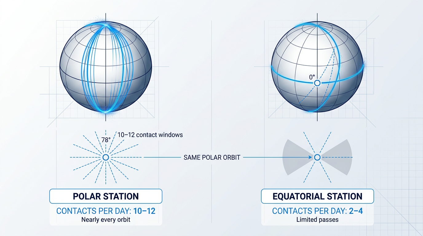
For satellites in near-polar orbits — which includes the majority of Earth observation and scientific LEO missions — the geometry strongly favours stations near the geographic poles. A satellite in a polar orbit passes over or near the poles on virtually every orbit, meaning a polar ground station can achieve contact on almost every pass.
ESA's documentation on its Kiruna station notes that its high-latitude position — at 67.9° North, above the Arctic Circle in northern Sweden — provides visibility for 10 to 12 out of 14 daily orbits for LEO satellites it supports. The KSAT Svalbard Ground Station (SvalSat), located at 78° North on Spitsbergen, Norway, sits even further poleward: ESA's own publications note it as the only station able to provide ground contact for all orbits of certain polar-orbiting satellites, making a single-site TT&C solution viable.
McMurdo Station in Antarctica serves the same geometric logic from the southern pole, and together these high-latitude facilities form the backbone of LEO data downlink infrastructure for polar-orbiting missions. NASA's Near Earth Network documentation confirms that stations in near-polar locations such as Norway, Alaska, and Antarctica can provide communications to polar-orbiting spacecraft on nearly every orbit.
The trade-off is real. Polar environments are operationally demanding — extreme cold, limited local infrastructure, and difficult logistics drive construction and maintenance costs significantly higher than at mid-latitude sites. The Leaf Space commercial ground station analysis notes that infrastructure in polar regions carries higher operational costs due to limited real estate and harsh environmental conditions. For missions with high data volumes and frequent contact requirements, however, the coverage efficiency typically justifies the investment.
Equatorial and Mid-Latitude Stations
Not every mission is polar. Geostationary (GEO) satellites, orbiting at approximately 35,786 km above the equator, appear stationary when viewed from equatorial latitudes. An equatorial ground station can therefore use a fixed-pointing antenna to maintain a permanent, uninterrupted link — no tracking required. This makes equatorial stations the natural choice for GEO TT&C and payload operations.
Mid-latitude stations serve a different purpose: supporting LEO constellations at lower orbital inclinations, where the satellite ground tracks do not reach the poles. NASA's Near Earth Network documentation notes that mid-latitude and equatorial stations provide support to LEO polar and low-inclination orbital missions, as well as lunar, Lagrange, and GEO spacecraft. The Wallops Island, Virginia station is cited as particularly well-positioned for low-inclination customers and launch tracking.
There is no universally optimal station latitude. The right placement depends entirely on the orbital regime of the satellite being served — a fact that immediately frames ground station network design as a mission-specific engineering problem, not a general infrastructure question.
Deep-Space Ground Stations: The NASA DSN
Interplanetary missions present a fundamentally different challenge: distances measured in hundreds of millions of kilometres, signals that arrive at Earth vanishingly faint, and the need for near-continuous contact as the planet rotates. NASA's Deep Space Network (DSN) was built specifically to meet this requirement.
The DSN consists of three Deep Space Communications Complexes — at Goldstone (California, USA), near Madrid (Spain), and near Canberra (Australia) — spaced approximately 120 degrees apart in longitude. As NASA describes it, before a distant spacecraft sinks below the horizon at one complex, another site can pick up the signal and carry on communicating, providing effectively continuous coverage for any point in the sky as Earth rotates.
Three complexes, placed 120 degrees apart in longitude, means Earth's rotation always keeps at least one DSN site in line of sight with any spacecraft in the solar system — an elegant geometric solution to the problem of continuous deep-space coverage.
Each DSN complex contains multiple large dish antennas. NASA's published documentation confirms that each site has one 70-metre antenna — the largest and most sensitive in the network, capable of tracking spacecraft tens of billions of miles from Earth — alongside multiple 34-metre beam waveguide antennas. The 70-metre dishes, weighing close to 2,970 US tons, are maintained to a surface precision of within one centimetre across their entire area.
ESA's ESTRACK: A Purpose-Built Global Network
ESTRACK — ESA's global tracking station network — illustrates how an institutional operator translates the placement principles above into a real, multi-mission network. Operated centrally from ESA's European Space Operations Centre (ESOC) in Darmstadt, Germany, ESTRACK is designed to cover near-Earth missions, LEO satellites, highly elliptical orbits, and deep-space missions from a single coordinated infrastructure.
| Station | Location | Antenna Size | Primary Mission Support |
|---|---|---|---|
| Kiruna | Salmijärvi, Sweden (67.9° N) | 15 m (KIR-1), 13 m (KIR-2) | LEO satellites; LEOP support; Earth observation (Sentinel, CryoSat, Swarm) |
| Kourou | French Guiana, South America | 15 m | Earth-orbiting spacecraft; launcher tracking; LEOP |
| Redu | Belgium | S- and Ka-band antennas | Galileo navigation; in-orbit testing of telecom satellites |
| Santa Maria | Azores, Portugal | 5.5 m | Launcher tracking; signal acquisition from Kourou launches |
| New Norcia (DSA 1) | Western Australia (140 km north of Perth) | 35 m | Deep-space missions (Mars Express, Solar Orbiter, Rosetta); LEOP acquisition aid |
| Cebreros (DSA 2) | 77 km west of Madrid, Spain | 35 m | Deep-space routine operations and back-up; radio science |
| Malargüe (DSA 3) | 30 km south of Malargüe, Argentina | 35 m | Deep-space routine operations and back-up; Delta-DOR tracking |
Key stations in ESA's ESTRACK core network, showing location, antenna size, and primary mission support role. The three 35 m Deep Space Antennas (DSA 1–3) are positioned roughly 120 degrees apart in longitude to provide continuous deep-space coverage.
The ESTRACK architecture reflects the placement logic discussed throughout this section. Kiruna's high-latitude position makes it the primary station for ESA's LEO Earth observation fleet. The three 35-metre Deep Space Antennas at New Norcia, Cebreros, and Malargüe replicate the same 120-degree longitudinal spacing principle used by NASA's DSN, providing continuous coverage for interplanetary missions. ESA's own documentation notes that the network is augmented through service contracts with commercial partners — including KSAT's Svalbard station and TrollSat in Antarctica — particularly for LEOP support, where the core network alone cannot provide the coverage density required.
In a typical year, the ESTRACK core network provides over 15,000 hours of tracking support to more than 20 missions, with a service availability rate above 99%, according to ESA's published network documentation.
The LEOP Requirement: Coverage by Mission Phase
Ground station network design cannot be optimised purely for steady-state operations. The Launch and Early Orbit Phase (LEOP) — the critical first days after a satellite separates from its launch vehicle — creates a specific and demanding coverage requirement that shapes network architecture.
During LEOP, mission controllers need near-continuous contact with the satellite to perform essential operations: deploying solar arrays and antennas, establishing attitude control, verifying subsystem health, and in some cases raising the spacecraft from its injection orbit to its operational orbit. ESA's BR/110 documentation states plainly that for all missions, nearly continuous contact with the spacecraft is necessary in the first few days of its life so that all initial critical operations can be performed reliably.
A single ground station cannot provide that continuous coverage. LEOP therefore requires a network of stations distributed along the satellite's ground track, with overlapping visibility windows that hand the spacecraft from one station to the next. The GOCE LEOP in March 2009 illustrates this directly: ESA's documentation records that tracking was successively handed over from Kiruna to Svalbard, then to Alaska and Troll (Antarctica), as the spacecraft orbited at approximately 285 km altitude with pass durations of six to nine minutes per station.
ESA's FAQ documentation notes that up to half a dozen ground stations — operated by ESA or partner networks — are typically called in to support LEOP, providing extra telecommanding passes and the flexibility needed when complex command sequences must be sent or problems must be resolved in real time.
Station Selection as a Strategic Decision
Orbital geometry explains where a station can be placed. It does not explain where an operator chooses to place it. That decision involves factors that have nothing to do with antenna pointing angles.
Regulatory jurisdiction is perhaps the most consequential. As covered in the frequency and licensing section of this guide, the country in which a station sits determines which national licensing framework applies. But jurisdiction goes further than frequency licences. SpaceNews reporting on the regulatory challenges facing smallsat operators highlights that establishing a ground station in a foreign country can give that country jurisdiction over the operator's satellite system — including potential legal intercept access to communications traffic. For defence and intelligence missions, this makes the political alignment of the host nation a primary selection criterion.
Inmarsat's approach to its Global Xpress network illustrates this directly: the company operates its ground stations in NATO and Five Eyes nations — a deliberate choice that keeps sensitive command and control infrastructure within trusted jurisdictions.
Data sovereignty concerns extend to commercial operators as well. For missions handling sensitive Earth observation data, financial data, or government imagery, the routing path from ground station to processing centre matters: data that transits through a foreign ground station may be subject to that country's legal frameworks. Operators with strict data residency requirements must factor this into station selection, sometimes accepting reduced coverage efficiency in exchange for a cleaner data governance posture.
Latency and data routing infrastructure add further constraints. A high-throughput Earth observation mission may downlink hundreds of gigabytes per orbit; the ground station must have the backhaul capacity to move that data to a processing centre quickly. A station in a geographically optimal location that lacks fibre connectivity or relies on slow terrestrial links may be operationally inferior to a less geometrically advantaged station with excellent infrastructure.
The result is that ground station placement is simultaneously an orbital mechanics problem, a regulatory problem, a data infrastructure problem, and a geopolitical one. The operators who understand all four dimensions make better network decisions than those who optimise for geometry alone.
With the spatial logic of station placement established — where stations go, why, and what they are designed to do — the natural next question is what actually happens during those contact windows. That is the territory of telemetry, tracking, and command operations, which the next section addresses in full.
Telemetry, Tracking, and Command: The Operational Heart of Mission Control
Strip away the science payload, the orbital mechanics, and the mission objectives, and every satellite reduces to a single requirement: someone on the ground must be able to hear it, locate it, and tell it what to do. Without that, the spacecraft is an object in orbit rather than a mission in operation. TT&C — telemetry, tracking, and command — is the irreducible operational minimum that makes the difference between the two.
No matter the orbit, the payload, or the mission lifetime, TT&C is non-negotiable. ESA's own ground systems documentation describes it as essential to virtually all spacecraft, and the architecture has been standardised across agencies for decades precisely because every mission needs it.
Telemetry: The Spacecraft's Continuous Health Report
Telemetry is the continuous downward flow of spacecraft health and status data from the satellite to the ground. The spacecraft's onboard computer packages this data into telemetry frames, which are transmitted on the downlink, demodulated and decoded by the ground station's receive chain, and then routed to the Mission Operations Centre for display and monitoring.
In practice, telemetry carries housekeeping data covering every critical subsystem: power bus voltages, battery state of charge, thermal readings across the spacecraft structure, attitude sensor outputs, propulsion system pressures, and payload status flags.
It also carries engineering parameters and out-of-limit flags that alert the operations team to anomalous conditions. ESA's ground systems reference notes that spacecraft health monitoring can involve the analysis of as many as five thousand telemetry parameters every minute during active operations.
The intensity of telemetry monitoring is highest during the Launch and Early Orbit Phase (LEOP), when the satellite is transitioning from its dormant launch configuration to a fully operational state. Solar arrays are being deployed, attitude is being acquired, and subsystems are being commissioned one by one — all while the full operations team watches for anything that could become a mission-ending anomaly if left uncorrected.
Telecommand: Sending Instructions to the Spacecraft
Telecommand is the upward flow of operator instructions from the ground to the spacecraft. Commands are generated at the Mission Operations Centre by operators or flight dynamics systems, validated for safety and sequence correctness, and then formatted for uplink.
The dominant international standard for command formatting and framing is CCSDS — the Consultative Committee for Space Data Systems. Before any command reaches the spacecraft's transmitter, it is structured into CCSDS-compliant transfer frames, complete with error detection and sequence control mechanisms that ensure the spacecraft receives commands in the correct order and can confirm their receipt.
Confirmation works through a telemetry echo: the spacecraft's Command Link Control Word (CLCW) is embedded in the downlink telemetry stream, allowing the ground to verify that each command frame was received and accepted. ESA's operational documentation notes that continuous monitoring is required to verify correct execution of commands during active operations.
Command authority and authenticated encryption are not optional extras — they are fundamental security requirements. An unprotected command link creates a vulnerability through which an unauthorised party could issue instructions to the spacecraft. NASA's ground data systems guidance states that operators must protect command authority using authenticated encryption from the point of command generation all the way to the spacecraft, ensuring that only the authorised mission control centre can command it.
Tracking: Knowing Where the Satellite Is
The third TT&C function — tracking — is the process by which the ground station determines the satellite's position and velocity. Two measurement techniques are used in combination.
Ranging measures the round-trip propagation time of a ranging signal transmitted from the ground station, retransmitted by the spacecraft's transponder, and received back at the ground. The time delay gives the distance between the station and the satellite. ESA's BR-110 ground systems reference notes that typical ESA ground stations achieve range measurement accuracy of approximately one metre.
Doppler shift measurement works differently: the ground station compares the frequency of the received downlink carrier against the transmitted uplink frequency. Because the spacecraft transponder derives its downlink frequency coherently from the received uplink, any shift in the received frequency reflects the satellite's radial velocity relative to the ground station. ESA's flight dynamics documentation describes this as calculating the spacecraft's radial velocity — its range rate — from the observed frequency shift.
These two measurements — range and range rate — feed into the flight dynamics system, which uses them for orbit determination: building and continuously refining a model of the satellite's actual orbit. That model then drives manoeuvre planning, including orbit correction burns and collision avoidance manoeuvres.
The Mission Operations Centre and Science Operations Centre
The Mission Operations Centre (MOC) is the nerve centre of every satellite mission. It is where all commanding originates, where telemetry from all ground stations is consolidated and archived, where ground station scheduling and control is managed, and where subsystem engineers monitor spacecraft health.
NASA's ground data systems documentation describes the MOC as typically a secure, controlled-access facility — protecting the satellite operating equipment and preventing unauthorised access to commanding systems. The Integral mission's MOC at ESOC, for example, is described as the sole interface to the satellite, responsible for monitoring and controlling it during all mission phases.
The Science Operations Centre (SOC) plays a distinct but complementary role. Where the MOC handles spacecraft health and operations, the SOC handles the science payload data: processing, archiving, and distributing science data products to the research community. NASA's architecture documentation defines the SOC as the focal point for all mission science data, generating and disseminating science data products and determining science operations requests that are relayed to the MOC.
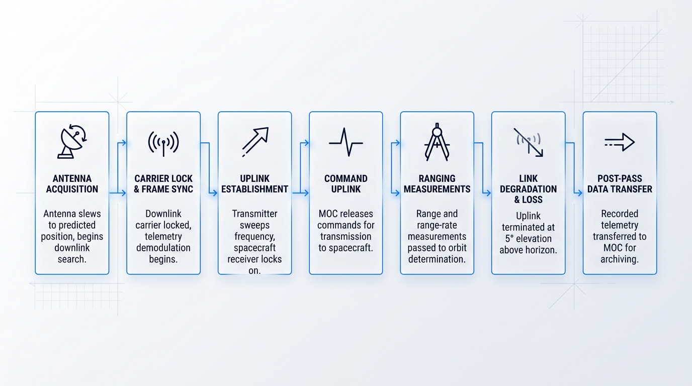
Inside a Contact Window: The Operational Sequence
A contact window — the period when the satellite is above the horizon and the ground station can communicate with it — follows a well-defined operational sequence. Understanding this sequence is essential context for appreciating the constraints that ground station operators face.
- Antenna acquisition: The ground station antenna slews to the predicted acquisition position, derived from the known orbit, and begins searching for the downlink signal.
- Carrier lock and frame sync: The station locks on to the downlink carrier; telemetry demodulation begins and housekeeping parameters start flowing to the MOC.
- Uplink establishment: The ground station transmits a carrier signal, sweeping around the nominal frequency to compensate for Doppler shift until the spacecraft's receiver locks on.
- Command uplink: With uplink lock confirmed in the telemetry, the MOC releases commands to the station for transmission to the spacecraft.
- Ranging measurements: While commanding and receiving telemetry, the station takes range and range-rate measurements, which are passed to the MOC for orbit determination.
- Link degradation and loss: As the satellite approaches the horizon, the link degrades. ESA documentation notes the uplink is terminated when antenna elevation falls to 5 degrees above the horizon.
- Post-pass data transfer: Telemetry recorded during the pass is transferred to the MOC for archiving and analysis, completing the contact cycle.
This sequence is operationally compact. For a LEO satellite, the entire window — from first signal to loss of contact — may last only a matter of minutes, making efficient execution of every step essential.
The LEOP period compresses all of this to its most demanding form. With the satellite transitioning from launch configuration to full operation, near-continuous ground station coverage is required — anomalies during this phase can be mission-ending if not caught and corrected immediately. ESA's Envisat operations documentation describes two mission control teams operating in two shifts, 24 hours per day, with a nine-station ground network deployed specifically to provide the coverage density that LEOP demands.
LEOP is the worst possible time to discover a ground segment problem. NASA and ESA both require pre-launch rehearsals with simulated anomalous telemetry inserted to test the team — because during the actual LEOP, there is no margin to diagnose and fix ground infrastructure while simultaneously commissioning a spacecraft that cannot wait.
The contact window workflow described here — from antenna acquisition through post-pass archiving — is the operational baseline that every ground station operator works within. The next section examines this baseline from a different angle: not what happens during a contact window, but what happens when contact windows are too short, too infrequent, or too contested to meet the mission's operational demands.
Operational Challenges: Contact Windows, Scheduling, Cost, and Reliability
Every satellite mission eventually confronts the same hard truth: no matter how capable the spacecraft, it can only be heard when it is overhead. The contact window is not a scheduling preference — it is a physical constraint imposed by orbital mechanics, and everything else in ground segment operations flows from it.
For a satellite in low Earth orbit, a single pass over a given ground station lasts roughly 5 to 15 minutes, depending on orbital altitude and the geometry of the pass. NASA documentation confirms that a LEO satellite passing directly overhead will be in view for around fifteen minutes, while a pass near the edge of the visibility circle may last only two to three minutes.
As covered in the section on station types and positioning, polar ground stations see polar-orbiting satellites far more frequently than mid-latitude stations do. The operational consequence is stark: a satellite served by a single mid-latitude station may accumulate only 40 to 50 minutes of total contact time per day, spread across brief, discontinuous passes.
That constraint shapes the entire mission operations concept. Onboard storage must be sized to hold data between passes. Anomalies detected in telemetry cannot be commanded against until the next window opens. Time-critical science observations that generate data faster than expected can exhaust onboard storage before a downlink opportunity arrives.
The contact window is not merely inconvenient — it is the bottleneck through which all mission value must pass, and the one that mission planners have the least ability to engineer away.
Scheduling Complexity in Multi-Mission Environments
When a single antenna must serve more than one satellite, the problem compounds rapidly. Satellites arrive at their contact windows on fixed orbital schedules, antenna slew rates are finite, and passes from different satellites can overlap. Scheduling deconfliction — the process of allocating antenna time across competing contact opportunities — is not a clerical task. It is a combinatorial optimisation problem.
Scheduling software exists to manage this, and the industry has invested significantly in automated tools. But even the best automated schedulers face hard constraints: a physical antenna can only point at one satellite at a time, and no algorithm eliminates that.
The ESA study on ground segment evolution makes the scaling challenge explicit: as a constellation grows from single digits to double digits in number, a conventional system's scalability is stressed and will eventually cease to function smoothly. Manual pass allocation techniques that work for small constellations become entirely infeasible as satellite counts grow — and the scheduling complexity grows faster than the number of satellites.
Moving from a handful of satellites to tens or hundreds does not simply multiply the scheduling workload — it changes its character entirely. Manual pass allocation ceases to be feasible well before a constellation reaches double digits, and the problem requires automated systems rather than human operators to remain tractable at all.
NASA's SBIR programme has funded development of machine-to-machine schedulers specifically because the manual process of current scheduling systems can take days or weeks to produce an optimised pass schedule — an entirely unacceptable latency for a growing constellation.
The SpaceNews reporting on ground systems preparing for mega-constellations captures the scale of the challenge plainly: you cannot operate 10,000 satellites the same way you operate two. The ground segment scheduling architecture must be rethought from first principles, not incrementally extended.
The Build-vs-Buy Decision for Ground Infrastructure
Building a dedicated ground station is a capital commitment that scales with aperture, frequency band, and site. NASA's SOA report states directly that the cost of a direct-to-Earth ground station is correlated with aperture size, which drives requirements for the foundation, pedestal, motors, and gear systems — larger dishes require stronger concrete foundations and larger motor and gearbox assemblies to handle wind loading.
Higher frequency bands demand more precise hardware throughout the signal chain, and remote or polar sites add logistics and operational costs on top of that. Leaf Space's published ground segment guidance puts an S/X-band antenna at approximately €400,000 to €500,000 for acquisition and shipping, with ongoing monthly maintenance costs of around €7,000.
Against those figures, a dedicated station sitting idle for the vast majority of each day — a satellite in LEO may only use it for 40 to 50 minutes out of every 24 hours — represents a poor return on capital for many mission profiles.
The build-vs-buy decision is not a universal answer. It is a function of mission duration, data volume, required contact frequency, and total cost of ownership. Leaf Space's analysis notes that for a six-month mission using S-band for payload operations, the cost of developing and operating a dedicated station is likely to exceed the cost of a ground station network subscription by a significant margin.
Longer missions, higher data volumes, or programmes requiring guaranteed contact scheduling at any time of day shift the economics the other way. The honest framing is that neither dedicated infrastructure nor commercial network access is inherently superior — the right answer depends on the specific mission parameters and how they evolve over the programme's lifetime.
Contractor Dependence as an Operational Risk
Operators who subscribe to commercial ground station networks gain flexibility and lower capital costs, but they surrender something in return: direct control over scheduling priority, contact timing, and the ability to respond immediately when something goes wrong on the spacecraft.
This is contractor dependence, and it is a genuine operational risk that mission planners must weigh explicitly — not a reason to dismiss commercial networks, but a trade-off that deserves honest accounting.
In a shared network, antenna time is a finite resource allocated across multiple customers. During periods of high demand, a given operator may find themselves lower in the scheduling queue than they would prefer. SpaceNews reporting on commercial ground station services confirms that in a shared network, access is on more of a first-come, first-served basis — whereas a dedicated or guaranteed antenna allows the operator to schedule activity at any time they need it.
The operational implication becomes sharpest during anomalies. When a spacecraft enters a safe mode or an unexpected event requires rapid commanding, the ability to schedule an unplanned pass immediately is critical. An operator dependent on a commercial network must work within that network's scheduling system and availability — which may not align with the urgency of the situation.
NASA research into automated scheduling frameworks notes that outages and failed contacts are far more common than issues with the spacecraft itself, and that recovery from a failed contact in a pre-scheduled system typically means waiting until the next planned pass. For time-critical missions, that latency is not always acceptable.
Satellite Today's reporting on smallsat operators using third-party ground infrastructure is frank on this point: even with a third-party provider, wrangling the ground segment remains difficult and complex, and the simplicity and low cost promised by ground outsourcing does not always materialise in practice.
Reliability Is Engineered In, Not Assumed
Ground station hardware fails. Receivers degrade, power systems trip, weather events interrupt links, and local outages can take a station offline without warning. Treating reliability as a property the ground segment simply has is a mistake — it is something operators must deliberately engineer into the system.
The primary mitigations operate at two levels. Within a single station, hardware redundancy — duplicate receivers, transmitters, and power systems — protects against component failures without interrupting service. ESA's ground segment architecture for safety-critical systems sets availability requirements that explicitly require redundancy at subsystem and equipment level to prevent service degradation.
But single-station redundancy cannot protect against site-level events: a severe weather system, a power grid failure, or a localised outage can take an entire facility offline regardless of how many redundant components it contains.
That is where site diversity becomes essential. Distributing ground stations across geographically separated locations means that a failure or weather event at one site does not end the mission. A satellite with access to stations at multiple sites can route its next contact through whichever facility is operational.
Emitter diversity — maintaining multiple antennas capable of serving the same satellite — extends this protection further. With both site diversity and emitter diversity in place, the system can tolerate simultaneous failures at individual components and individual sites without losing contact with the spacecraft.
These diversity architectures are a deliberate engineering choice, not a default configuration. They carry cost and complexity, and operators must decide explicitly how much redundancy the mission warrants. The same diversity principles will prove equally important in the context of emerging optical ground links, where cloud cover introduces its own availability threat — but that is a discussion for the next section.
Hardware Procurement: In-House Engineering vs. Catalogue Supply
One operational risk that rarely appears in technical guides but matters considerably in practice is the depth of engineering support behind the hardware itself.
Operators who source ground station hardware from manufacturers with genuine in-house design and build capability — teams that designed the equipment, understand it at component level, and can modify it — gain meaningful advantages under operational pressure: faster spares, deeper troubleshooting, and the ability to adapt hardware to specific programme requirements that catalogue products were never designed to accommodate.
Operators who source from resellers or importers of catalogue products may find that support is slower, that adaptation is limited or impossible, and that when something fails in an unusual way, the supplier has no deeper knowledge of the product than the operator does.
For non-critical applications, that distinction may be acceptable. For mission-critical ground infrastructure where a hardware failure means lost contact with the spacecraft, it is a procurement decision with direct operational consequences — and one worth examining explicitly before committing to a supplier.
The challenges described in this section — constrained contact windows, scheduling complexity, capital costs, contractor dependence, and reliability engineering — are real and persistent. They are also, to varying degrees, addressable. One of the most significant structural responses the industry has developed is the commercial ground station network model, which trades some control for access to distributed infrastructure at scale. That model, its genuine advantages, and its genuine trade-offs are the subject of the next section.
Ground Station as a Service: Build vs. Buy
The cost and scheduling pressures covered in the previous section have a direct commercial answer: pay for antenna time only when you need it, on infrastructure someone else has already built, licensed, and staffed. That is the core proposition of Ground Station as a Service (GSaaS) — and for many operators, particularly those flying small satellites or running short-duration missions, it represents a genuinely compelling alternative to building dedicated ground infrastructure.
As defined by NASA's Ground Data Systems State-of-the-Art reports, GSaaS is a managed service that enables customers to communicate with, downlink data from, and in some cases process data from their satellites on a pay-as-you-go basis, without needing to build or operate their own ground stations.
The economic logic is straightforward: a commercial ground station network spreads the large fixed costs of antenna hardware, facilities, regulatory licensing, operations staff, and maintenance across many customers simultaneously. What would cost a single operator millions to replicate independently becomes accessible at per-pass or per-minute pricing.
The model is most compelling for missions with moderate contact requirements, short operational lifetimes, or budgets that cannot absorb capital expenditure on ground infrastructure. Leading GSaaS providers also integrate directly with cloud data platforms, so data flows from the satellite through the ground station and into the operator's cloud environment as a single managed pipeline.
Major Commercial GSaaS Providers
AWS Ground Station is Amazon Web Services' fully managed ground station network, enabling customers to control satellite communications, process data, and scale operations without building or managing their own ground station infrastructure.
The network spans twelve antenna sites globally — Alaska, Hawaii, Oregon, Ohio, Ireland, Stockholm, Cape Town, Bahrain, Singapore, Dubbo, Punta Arenas, and Seoul — each positioned in close proximity to AWS infrastructure regions to minimise data transport latency.
Scheduling is available on a per-minute basis with no long-term contracts. Data is delivered directly into AWS services including Amazon S3, Amazon EC2, Amazon Kinesis Data Streams, and Amazon SageMaker, enabling near-immediate processing after downlink. AWS states that operators can save up to 80% on ground station operations costs compared to building their own infrastructure.
The network supports LEO, MEO, and non-geostationary orbit satellites, operating in S-band uplink and S-band and X-band downlink.
Kongsberg Satellite Services (KSAT) is one of the largest and most established commercial ground station operators in the world, with a global network comprising more than 300 antennas across 28 selected locations.
KSAT conducted 2.1 million satellite contacts during 2024, according to its published annual report. Its polar station at Svalbard — at 78° North — is the world's largest commercial ground station and can capture all 14 daily orbits for sun-synchronous missions, giving KSAT a structural advantage for LEO operators in polar and sun-synchronous orbits.
KSATlite is KSAT's dedicated service tier for small satellites and constellations: a standardised, software-defined network with small-aperture antennas at 26 distributed locations, supporting S-band, X-band, and Ka-band, with per-pass scheduling and automated operations via API. KSATlite handled over one million contacts in 2023 from approximately 100 dedicated antennas. KSAT also provides dedicated licensing support through its own regulatory teams.
The GSaaS market extends well beyond these two providers. The sector is competitive and growing, with multiple operators offering managed ground network services globally — operators evaluating the market should expect to find additional providers with different network footprints, pricing models, and service profiles.
| Provider | Network Scale | Pricing Model | Cloud Integration | Key Strength |
|---|---|---|---|---|
| AWS Ground Station | 12 antenna sites globally | Per-minute, no long-term contracts | Native: S3, EC2, Kinesis, SageMaker | Direct cloud pipeline; AWS ecosystem integration |
| KSAT / KSATlite | 300+ antennas, 28 sites; KSATlite: 26 sites | Per-pass scheduling via API | Cloud integration with public platforms | Polar coverage; 2.1M contacts in 2024; LEO/SSO strength |
AWS Ground Station and KSAT compared across network scale, pricing model, cloud integration, and primary positioning. Dollar-amount pricing is not publicly listed by either provider.
The two providers differ substantially in character despite both serving the GSaaS market. AWS Ground Station is built around tight cloud integration for operators already inside the AWS ecosystem; KSAT's strength lies in network scale, polar station access, and a proven track record across a very large volume of commercial LEO passes. Neither is universally superior — the right fit depends on the operator's orbit, data pipeline, and operational priorities.
Onboarding: Not Plug-and-Play
GSaaS is often presented as a simple, frictionless alternative to building ground infrastructure — and operationally, once active, it can be. But getting to that point requires significant lead time that operators frequently underestimate.
Ground segment providers, speaking to SpaceNews, recommend that operators approach them anywhere from a year to 18 months before launch. Dan Adams, KSAT USA CEO, noted that 12 months provides enough margin because KSAT "should be in a position of signing contracts six months out." Christopher Richins, RBC Signals co-founder and CEO, recommends starting 18 months beforehand, adding: "There's no penalty for doing it earlier."
The onboarding process involves three substantive workstreams. Frequency licensing alignment requires the operator's RF licence to be compatible with the provider's licensed frequencies at each station — and national regulators can take months or more to issue a ground station licence, with some jurisdictions requiring an ITU filing before a licence request can even be submitted.
Compatibility testing verifies that the satellite's radio system works correctly with the provider's ground equipment, often using digital twin or simulation tools before launch. The operator must also share mission parameters — orbital elements, link budgets, scheduling requirements — so the provider can configure the network appropriately.
Ground segment providers recommend engaging 12 to 18 months before launch — not after. Regulatory licensing alone can take months in some jurisdictions, and operators who arrive late risk being unable to support LEOP from day one.
For missions with unusual waveforms, non-standard modulation schemes, or specialised frequency plans, the lead time requirement is more acute still — ground segment experts advise such operators to engage providers years before launch to establish whether the commercial network can accommodate their requirements at all.
Genuine Advantages of GSaaS
- No capital expenditure: Operators pay only for antenna time used. Building an S/X-band antenna system independently runs to hundreds of thousands of euros before operational costs.
- Distributed coverage immediately: Instant access to geographically spread stations, including polar sites that would be prohibitively expensive to build and operate independently.
- Scalable on demand: Contact frequency can be increased or decreased as mission needs evolve, without hardware investment or infrastructure change.
- Regulatory groundwork done: Providers have already navigated complex licensing across multiple jurisdictions; operators benefit from that work without replicating it themselves.
- Cloud-integrated pipelines: For providers like AWS, data flows from orbit directly into the operator's cloud environment, enabling near-real-time processing after downlink.
These advantages are most pronounced for small satellite operators, technology demonstration missions, and early-stage commercial programmes where capital constraints are real and mission duration is limited.
Genuine Trade-offs of GSaaS
The trade-offs deserve equal honesty. Reduced scheduling control is the most operationally significant: the operator competes with other customers for antenna time on a shared network. During high-demand periods, or for time-critical operations such as anomaly response or Launch and Early Operations Phase (LEOP) support, the operator cannot simply command the antenna — they are in a queue alongside other missions.
Contractor dependence is more acute in a fully outsourced ground segment than when a commercial network supplements dedicated infrastructure. When the provider's network is the operator's only means of communicating with their satellite, mission continuity is directly contingent on the provider's infrastructure reliability, support quality, and commercial continuity — a dependency that warrants careful due diligence on provider track record and contractual protections.
Finally, reduced configuration control can constrain missions with specialised technical requirements. Operators work within the hardware and software the provider's network offers and cannot customise antenna systems or signal processing chains to mission-specific needs. For missions with unusual RF designs or specialised processing requirements, this may be a hard constraint rather than a minor inconvenience.
The Build-vs-Buy Decision Framework
Neither model is universally superior. The right answer is a function of mission-specific parameters, and the variables that push in each direction are well-defined.
The case for dedicated ground infrastructure strengthens with mission duration (capital cost amortises over more years), very high data volumes requiring frequent or continuous contact, latency-sensitive applications where scheduling delays carry operational cost, and missions with specialised technical requirements that commercial networks cannot accommodate. Large institutional missions and high-data-rate commercial constellations often still require dedicated or semi-dedicated infrastructure for these reasons.
The case for GSaaS strengthens with short mission duration, moderate data volumes, budget constraints that make capital expenditure impractical, and missions where the flexibility of per-pass pricing is more valuable than scheduling control. The economic case is particularly strong for small satellite missions and technology demonstrators where the mission may be complete before a dedicated station could even be built and licensed.
A hybrid approach is also viable: some operators use commercial networks for routine contact and data downlink while retaining a small dedicated capability for time-critical operations such as LEOP and anomaly response — capturing the cost benefits of GSaaS without fully surrendering scheduling control.
The commercial service model is one dimension of how the ground segment is evolving. A separate and equally significant dimension involves the underlying technology — new approaches to ground segment design that are reshaping what is physically possible in the link between satellite and Earth.
Optical Ground Links and the Future Ground Segment
The RF spectrum is not infinite. Every frequency band covered in this guide — S, X, Ka, and beyond — is a shared, licensed, and increasingly congested resource, and the physics of radio imposes a hard ceiling on how much data any given link can carry at a given terminal size and power. Mission planners who need to move large volumes of Earth observation, science, or imagery data are running into that ceiling. Free-space optical (FSO) communications are the technically logical response: not a speculative future technology, but a maturing field that serious mission architects are already evaluating and deploying.
How FSO Communications Work
Free-space optical links use lasers at near-infrared wavelengths — typically 1064 nm or 1550 nm — to carry modulated data through free space, operating at far higher frequencies than any RF band and exploiting the correspondingly wider available bandwidth.
The data rate advantage is not incremental. NASA's TBIRD (TeraByte InfraRed Delivery) mission demonstrated 200 Gbps downlinks from a 6U CubeSat in LEO — a figure that dwarfs what RF systems can deliver at equivalent terminal size and power.
NASA's TBIRD mission demonstrated 200 Gbps optical downlinks from a 3U payload on a 6U CubeSat, delivering over 4.8 terabytes of data error-free in a single five-minute pass — more than 1,000 times the rate of a typical small satellite radio link.
At those rates, a single LEO pass can deliver multiple terabytes of data — volumes that would require hours or days over an RF downlink, and that RF technology at comparable terminal scale simply cannot match.
The Challenges of Optical Ground Links
Optical links are not without trade-offs. Three challenges define the engineering problem at the ground station, and honest mission planning requires all three to be addressed.
- Pointing, acquisition, and tracking: Optical beams are orders of magnitude narrower than RF beams. Acquiring and holding lock on a fast-moving LEO satellite demands sub-microradian pointing precision — a fundamentally harder problem than RF antenna tracking.
- Atmospheric turbulence: Turbulence causes beam spreading and scintillation — rapid intensity fluctuations that degrade link quality. Coherent detection systems require adaptive optics to correct the wavefront distortion introduced by the atmosphere.
- Cloud cover: Unlike RF, an optical beam cannot penetrate cloud. A single overcast site means a lost contact window, with no fallback within that link architecture.
These are real constraints, not minor caveats — and they shape everything about how optical ground stations are designed, sited, and networked.
How Optical Ground Stations Differ from RF Stations
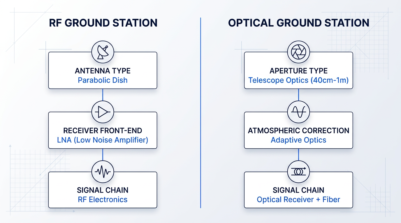
An optical ground station looks nothing like its RF counterpart. Where RF stations use parabolic dish antennas, optical stations use telescope apertures — typically 40 cm to 1 m for LEO missions — with optical-quality mirror surfaces designed to focus collected light onto a receiver.
NASA's SOA Communications documentation notes that optical ground stations are often located at or near astronomical telescope sites, chosen for their favorable "seeing" environments: low cloud cover and calm, non-turbulent air.
High-rate coherent downlinks require adaptive optics subsystems to correct atmospheric wavefront distortion before the signal can be coupled into a single-mode fibre receiver — a capability that has no equivalent in the RF front-end.
The full optical chain at a ground station — telescope, adaptive optics, detector, and uplink amplifier — is a distinct engineering discipline from the RF signal chain described earlier in this guide.
Site Diversity and Emitter Diversity
Site diversity is the primary architectural response to cloud cover: by distributing optical ground stations geographically, network operators ensure that when one site is overcast, another can complete the contact window.
Emitter diversity — deploying multiple transmitters at a single site — addresses a different problem: atmospheric fading within a single pass, where independent beam paths through the atmosphere reduce the probability of simultaneous signal loss.
Both strategies are architectural decisions made at the network design stage, and they have direct implications for the uplink amplifier hardware at each site.
Uplink Amplification: A Real-World Example
The uplink amplifier is a critical component of the optical ground station's transmit chain — it is the device that takes the ground station's outgoing optical signal and amplifies it to the power levels needed to close the link with a satellite. The technology class used for this purpose is the erbium-doped fibre amplifier (EDFA), operating in the 1550 nm C-band where terrestrial fibre telecom has driven components to high maturity.
Our EDF-UL platform, developed by Woodrow Scientific Limited, illustrates what this technology class looks like when it is built specifically for the satellite ground station application rather than adapted from a general-purpose catalogue product.
The defining architectural feature of the EDF-UL is its single-beam beacon and data capability: the tracking beacon and uplink data are nested in one amplified beam, with the beacon riding at low amplitude and the data modulated above it via amplitude modulation. This means the ground station does not need separate optical paths for acquisition, tracking, and data transmission — all three operating modes are served by a single amplified output.
The platform is also extensively configurable across both hardware and software. On the hardware side, it can be built to C-band, L-band, or dual-band; configured for 2- or 4-emitter arrays with synchronisation for site and emitter diversity architectures; fitted with an external optical input port for third-party transmitters; and cooled by air or water depending on installation constraints. On the software side, WSL's Modulation-on-Demand system allows the waveform, frequency, and modulation index to be set in software, with the ability to switch between CCSDS, SDA, and proprietary standards at high power — without any hardware change.
This software-definability matters beyond operational convenience. Standards for optical ground-to-space links — including CCSDS and Space Development Agency protocols — are still evolving, and an amplifier that can be reconfigured as those standards develop protects the ground station investment over time.
The distinction between a manufacturer and a reseller matters here in ways that are not always visible at procurement. Many suppliers in this category import or resell catalogue amplifiers with limited ability to adapt either the hardware or the control layer. WSL designs, builds, qualifies, and supports the EDF-UL entirely in-house, on patented technology, with engineering rooted in Southampton's Optoelectronics Research Centre — the institution where the EDFA was invented. That depth of in-house capability means the amplifier can be configured to the specific ground station, and that engineering support and spares remain available from the people who built it. The EDF-UL is CE and UKCA certified and manufactured in the UK.
Software-Defined Ground Systems
The shift toward software-defined ground systems is a parallel trend to the optical layer, not subordinate to it. Dedicated hardware for modulation, demodulation, signal formatting, and protocol handling is being replaced by software running on generic servers — allowing ground station functions to be reconfigured without physical changes to infrastructure.
NASA's Ground Data Systems State-of-the-Art documentation describes this shift explicitly: virtualised, IP-based architectures enable ground station functions to be orchestrated dynamically, and software-defined architectures are characterised as more agile, programmable, and automated than their hardware predecessors.
The investment-protection argument is the same one that applies to the optical uplink layer: protocols and standards are still evolving, and a ground system that can adapt in software rather than requiring hardware replacement is better positioned to remain compatible as the operational environment changes.
The Hybrid RF/Optical Architecture
The near-term operational model is not a wholesale replacement of RF by optical, and the research literature is clear on this point: as a NASA NTRS paper on integrated radio-optical communications states, all optical missions have radio support.
The hybrid RF/optical architecture is pragmatic rather than transitional. Optical links carry high-volume data downlinks where throughput is the priority; RF links provide reliable TT&C and all-weather backup coverage that optical links cannot guarantee.
The two systems are complementary by design. RF's ability to close a link through cloud cover and rain is not a weakness of optical — it is a feature of the hybrid architecture that optical links are not expected to replicate.
Further Emerging Trends
Beyond optical links and software-defined architectures, three additional trends are reshaping how ground segments are operated at scale: AI-assisted scheduling, which is becoming necessary as constellation sizes grow beyond what manual operations can support; cloud-integrated data processing, which allows science data to be routed and processed without centralised physical infrastructure; and phased array antennas, which offer the ability to track multiple satellites simultaneously without mechanically steered dishes.
NASA's SOA Ground Data Systems editions identify FSO communications and phased array ground systems as the two primary emerging solutions for handling the data volumes that large constellations will generate — both technologies now beginning to be integrated into operational ground networks after years of development.
Together, these architectural directions — optical links, software-defined infrastructure, hybrid RF/optical operation, and AI-assisted management — define the trajectory the ground segment is on, and they set the context for understanding what the satellite ground station of the next decade will look like.
Conclusion
The Ground Segment: Engineering the Link Between Space and Earth
A satellite without a ground segment is simply an object in orbit — it is the infrastructure on Earth that gives a mission its voice, its health, and its purpose.
The field is advancing rapidly, and the pressures are advancing with it: greater capability and greater complexity are not in tension so much as they are inseparable.
Operators who treat the ground segment as a full engineering discipline — not an afterthought to the spacecraft — are the ones who will get the most from both.
Frequently Asked Questions About Satellite Ground Stations
Answers to common questions about how satellite ground stations work, what they cost, and how they communicate with satellites.
Satellite ground stations are the terrestrial interface of a satellite system, performing three core functions: receiving telemetry (spacecraft health and science data), transmitting telecommands (instructions to the spacecraft), and tracking and ranging (determining the satellite's position and velocity). Together these are known as TT&C — Telemetry, Tracking, and Command. Beyond TT&C, ground stations route mission data from the satellite onward to the Mission Operations Centre (MOC), where commanding is generated and telemetry is archived, and to the Science Operations Centre (SOC), which generates and disseminates science data products. In this way, the ground station is not merely a receiver — it is the critical link between the spacecraft and every team that depends on its data.
In TT&C operations, tracking is the function by which a ground station determines where a satellite is and how fast it is moving. It works by measuring two things: the round-trip propagation time of a ranging signal (which gives the distance to the satellite) and the Doppler shift of the received carrier frequency (which gives the satellite's radial velocity). These measurements feed into flight dynamics systems — such as those operated by ESA's ESOC — that calculate and predict the satellite's orbit with high precision. The resulting orbital data serves two practical purposes: it enables the ground station antenna to be pointed accurately during the next pass, and it supports manoeuvre planning so operators can adjust the spacecraft's trajectory when required. Tracking is distinct from telemetry (health data) and command (instructions) — it is specifically about knowing where the spacecraft is at all times.
Cost varies enormously depending on aperture size, frequency band, and capability. A basic UHF/VHF station can be assembled for tens of thousands of pounds using turnkey kit solutions — ISISpace, for instance, lists VHF/UHF ground station kits from around €62,500. A professional S-band or X-band station with tracking capability scales into the hundreds of thousands. Large deep-space antennas of 34 metres and above cost tens of millions to build and operate. For most commercial and small satellite operators, these capital costs make dedicated infrastructure difficult to justify. Ground Station as a Service (GSaaS) networks offer an alternative: operators pay only for the antenna time they use, with no upfront hardware expenditure. The trade-off is real, however — GSaaS saves capital cost but gives operators less direct control over scheduling, and they depend on the provider's reliability and support quality rather than their own infrastructure.
Communication happens through a radio frequency (RF) link — or, increasingly, an optical (laser) link. The ground station's antenna focuses electromagnetic energy towards the satellite; modulated signals carry data and commands in both directions. On the uplink, the station transmits commands; on the downlink, the satellite returns telemetry and payload data. One fundamental physical constraint governs every contact: the satellite must be above the horizon for communication to occur. For satellites in low Earth orbit, this limits each pass over a given ground station to roughly 5 to 15 minutes. Outside that window, the satellite is out of line of sight and no direct contact is possible. This is why ground station placement, network coverage, and pass scheduling are central challenges in satellite operations — and why operators with time-critical missions often invest in networks of stations at multiple geographic locations.
RF links use radio waves — typically in S, X, Ku, or Ka band — and are the established standard for TT&C and data downlink. They function in all weather conditions, are well-regulated under international spectrum frameworks, and have decades of operational heritage. Optical (free-space optical, or FSO) links use lasers at near-infrared wavelengths, typically around 1,064 nm or 1,550 nm. Because optical frequencies are orders of magnitude higher than RF, they can carry far greater data volumes: NASA's TBIRD mission demonstrated a 200 Gbps downlink from a 6U CubeSat, transferring 4.8 terabytes in a single five-minute pass — a throughput simply not achievable over RF. The trade-off is significant: optical links require extremely precise pointing, are blocked by cloud cover, and demand adaptive optics at the ground terminal to correct atmospheric distortion. Because optical links can be interrupted by weather, hybrid RF/optical architectures are increasingly the most capable approach — optical for high-volume data downlink, RF for reliable all-weather TT&C and backup coverage.
Ground Station as a Service (GSaaS) is a commercial model in which satellite operators pay for antenna time on a third-party network rather than building their own ground stations. As NASA's SOA Ground Data Systems report describes it, GSaaS is a managed service enabling customers to communicate, downlink, and process data from their satellites on a pay-as-you-go basis without building their own infrastructure. Providers such as AWS Ground Station and KSAT operate global antenna networks and charge on a per-minute basis — AWS Ground Station, for example, bills by the minute with no long-term commitment required. KSAT's KSATlite network operates over 100 small-aperture antennas across more than 15 sites globally. GSaaS eliminates capital expenditure and provides immediate access to geographically distributed stations, which is particularly valuable for operators who need polar or multi-latitude coverage without the cost of building it themselves. The real trade-off is reduced scheduling control: operators depend on the provider's availability, reliability, and support quality rather than having dedicated infrastructure under their own management.