

Introduction
Whether you are an engineer specifying hardware for a new ground station, a procurement professional weighing suppliers against a long-term programme, or a technical buyer responsible for a deployment that has to work in demanding conditions, the decisions ahead of you are genuinely complex.
Good information on satellite communications equipment is not hard to find — but most of it stops at definitions, leaving the harder questions unanswered.
This guide addresses those harder questions: the trade-offs between frequency bands, the realities of integrating new hardware with legacy systems, what ruggedisation demands, how to evaluate a supplier's long-term viability, and where emerging technologies are headed.
By the end, you will have a decision framework — the structured thinking to evaluate equipment confidently and ask the right questions before committing.
TL;DR
Most technical guides on satellite hardware tell you what the equipment is. The ones that actually help procurement and engineering decisions tell you how to choose — weighing band trade-offs, integration constraints, environmental requirements, and supplier risk together. That is the gap this guide fills: a structured framework for decisions that encyclopaedic definitions cannot support.
This article covers:

Core hardware components and system architecture
Frequency band trade-offs and use-case fit
Integration complexity and legacy compatibility
Ruggedisation and environmental qualification
Supplier evaluation and lifecycle risk
Emerging technologies: optical links and LEO
What is satellite communications equipment?
The term gets used loosely — sometimes to mean the satellite itself, sometimes to mean a broadband subscription, sometimes to mean a dish on a roof. For engineers and procurement professionals specifying a real system, that ambiguity is costly. Satellite communications equipment refers specifically to the physical hardware used to transmit, receive, and process satellite signals: the antennas, modems, amplifiers, transceivers, terminals, and frequency converters that form the working stack on the ground and at the user site.
This hardware category does not include the orbital spacecraft, and it does not include the satellite service — the capacity, subscription, or network management layer. Those are context for what the equipment must interface with, not the subject of procurement. The distinction matters because the hardware stack is where engineering decisions are made, where integration complexity lives, and where lifecycle risk is carried.
The standard industry framework for organising a satellite communications system is the three-segment model: the space segment (the satellite — its transponders, onboard antennas, and power systems), the ground segment (earth stations, gateways, and teleports that connect to the broader network), and the user segment (VSAT terminals, portable terminals, and mobile platforms at the point of use).
This guide focuses on ground segment and user segment hardware — the equipment a buyer actually procures, installs, and operates. The space segment is background: it defines the link conditions the ground hardware must satisfy, but it is not something the buyer specifies or maintains.
How a satellite link is formed
Understanding what each piece of hardware does is easier once you can trace the signal through the system end to end. On the uplink, a transmitting earth station starts with a baseband signal — voice, data, video. The modem modulates it onto an intermediate frequency (IF) carrier. A Block Upconverter (BUC) translates that IF signal to the RF frequency band used on the satellite link. A High-Power Amplifier (HPA) or Solid-State Power Amplifier (SSPA) then drives the signal to the power level needed to reach the satellite, and the antenna focuses that energy into a directed beam aimed at the spacecraft.
At the satellite, the transponder receives the uplink signal, shifts it to a different frequency to avoid interference with the uplink, amplifies it, and retransmits it back toward Earth as the downlink. At the receiving terminal, the antenna captures the downlink, and a Low-Noise Block downconverter (LNB) or Low-Noise Amplifier (LNA) amplifies the weak received signal while adding as little noise as possible, converting it to IF. The modem then demodulates the IF signal back to baseband, recovering the original data.
Each hardware category in that chain has a distinct, non-substitutable role. The five that appear throughout this guide are:
- Antenna: Captures and focuses the signal in both directions; aperture size directly determines gain, which governs how much signal energy is collected or directed.
- HPA / SSPA: Amplifies the uplink signal to the power level required to close the link to the satellite; the primary determinant of transmit power budget.
- LNB / LNA: Conditions the received downlink signal immediately at the antenna feed, amplifying it with minimum added noise before further processing.
- Modem: Modulates and demodulates the baseband signal; the intelligence layer of the link, handling coding, framing, and adaptive data rate control.
- Frequency Converters (BUC / LNB): Translate signals between the IF or baseband domain and the RF frequencies carried on the satellite link in both the transmit and receive directions.
Knowing what each component does in isolation is necessary but not sufficient — what matters for system performance is how those components combine, and two figures of merit capture that combination precisely.
EIRP (Effective Isotropic Radiated Power) characterises the transmit side of the link. It is the product of the transmitter's output power and the antenna's gain, expressed in dBW, and it determines how strong the signal is at the satellite's receive antenna. A higher EIRP means either more transmit power, a larger or more efficient antenna, or both.
G/T (Gain-over-Noise-Temperature) characterises the receive side. It combines the antenna's gain with the total noise temperature of the receiving system, and it determines how effectively a terminal can extract a signal from background noise. A terminal with a high G/T can work with a weaker downlink signal — which has direct implications for antenna size, LNA quality, and system architecture.
Every antenna size, amplifier power level, and LNA noise figure ultimately feeds into either EIRP or G/T. These two figures are the common currency between hardware specification and link budget analysis — understanding them is the prerequisite for evaluating any equipment trade-off.
Before any component can be specified, however, one upstream decision shapes everything else: the choice of frequency band. Whether a system operates in C, Ku, Ka, X, L, or S band determines the required antenna aperture, the amplifier power levels, the regulatory licensing pathway, and the system's sensitivity to atmospheric conditions. This is the first and most consequential hardware decision in any SATCOM procurement, and it is examined in depth in the frequency band trade-offs section later in this guide.
With the vocabulary established and the system architecture in view, the next step is to examine each hardware category in detail — how component choices interact, what the integration dependencies are, and what distinguishes equipment suited to demanding operational environments from commodity hardware.
Core Hardware Components and How They Work Together
Knowing what each piece of satellite communications equipment does is the starting point — but the decisions that determine whether a system actually performs come from understanding how choices in one component constrain and shape every other. Antenna aperture feeds directly into link margin. Amplifier linearity determines which modulation schemes are viable. LNB noise figure sets the receive noise floor that the entire downlink budget must work around. These dependencies run through the system like a chain: pull one link and the others move.
Antennas: Aperture, Gain, and Beam Steering
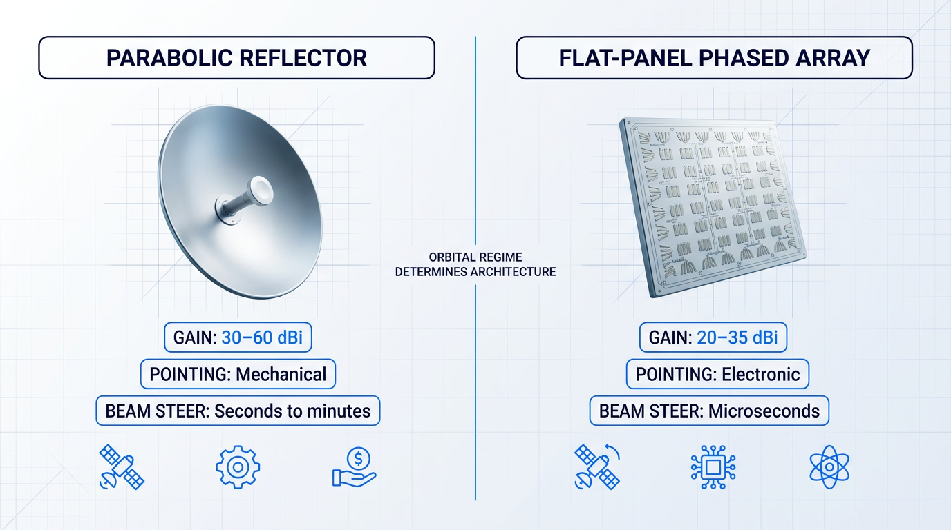
Aperture size is the primary driver of antenna gain — a larger collecting area focuses more energy into the link, directly improving both EIRP on transmit and G/T on receive. According to IEEE, parabolic reflectors achieve gains of 30 to 60 dBi across aperture diameters of 0.5 to 12 metres, depending on frequency.
For fixed GEO deployments, the parabolic reflector remains the dominant choice: high gain, mechanically straightforward, and cost-effective at scale. Once pointed at a geostationary orbital slot, it requires no active beam steering — the satellite stays fixed relative to the Earth's surface. Offset-fed designs eliminate aperture blockage by the feed support structure, pushing aperture efficiency as high as 80 percent, and carbon fibre reflectors maintain dimensional stability under thermal extremes that would distort aluminium alternatives.
The calculus changes entirely for non-geostationary applications. A LEO satellite at 1,000 km altitude crosses the sky at roughly 7.3 km/s, making mechanical tracking of individual satellites impractical for cost-sensitive terminals. Flat-panel phased arrays solve this through electronic beam steering: by applying controlled phase shifts across an array of radiating elements, the beam repoints in microseconds rather than the seconds or minutes a mechanically steered dish requires.
That speed comes at a cost. Phased arrays are significantly more complex and power-hungry than parabolic reflectors, and flat-panel designs based on printed circuit board technologies carry higher insertion losses than waveguide-based structures — losses that compound at higher frequencies. The antenna architecture is therefore not a preference but a consequence of the orbital regime and mobility requirements: fixed GEO points to a dish; LEO tracking or on-the-move operation points to a phased array.
High-Power Amplifiers: TWTAs, SSPAs, and the GaN Transition
The two dominant HPA technologies — travelling-wave tube amplifiers (TWTAs) and solid-state power amplifiers (SSPAs) — occupy different parts of the efficiency-linearity trade-off space, and the right choice depends on the power level and signal type the system demands.
TWTAs hold a persistent efficiency advantage at medium and high power levels. Trade press analysis from Satellite Magazine shows that at linear power levels above roughly 100 W (C-band) or 30 W (Ka-band), TWTAs deliver meaningfully better prime power efficiency than SSPAs — a difference that translates directly into lower operating costs and reduced cooling requirements, particularly relevant in hub and gateway installations running continuously.
SSPAs counter with superior linearity near saturation. A typical SSPA can achieve the same usable linear output power as a TWTA rated at two to three times higher saturated power, because SSPAs require far less back-off to meet intermodulation distortion limits. This matters acutely for multi-carrier operation and higher-order modulation schemes — 16APSK and 32APSK are far more sensitive to amplifier non-linearity than QPSK, so the amplifier's linearity directly constrains which modulation schemes the system can run. SSPAs also carry no consumable vacuum tube, eliminating the finite tube-life maintenance consideration that TWTA installations must plan around.
The ongoing transition from GaAs to GaN transistors in SSPAs is reshaping the lower and mid-power segment of this trade-off. GaN devices achieve up to five times the output power of GaAs over the same bandwidth, with higher power density, improved prime power efficiency, and a smaller thermal footprint. Statistical reliability data published in trade press shows GaN-based SSPAs achieving a 65 percent improvement in MTBF over equivalent GaAs designs under controlled manufacturing conditions. For system designers specifying SSPAs today, GaN is effectively the default technology — GaAs development has largely ceased as R&D investment concentrates on GaN.
One practical nuance worth noting: GaN devices exhibit a characteristic IMD floor at around 2 dB of output back-off that does not improve with further back-off, and their P1dB compression point sits 5 to 6 dB below saturated power — making PSat a misleading rating metric. System designers specifying GaN BUCs should evaluate linear power (Plin) against intermodulation and spectral regrowth specifications, not saturated output power alone.
Receive Chain: LNBs, LNAs, and Noise Figure
The noise figure of the first receive-chain component is disproportionately important to overall system performance. The Friis noise formula establishes why: the first stage's noise contribution dominates the cascade, with each subsequent stage's contribution attenuated by the gain of everything preceding it. Placing a low-noise amplifier as early in the receive chain as possible — before any cable loss or mixing stage — is a foundational principle of receiver design.
For satellite ground terminals, this means the LNB's noise temperature sets the effective noise floor for the entire downlink receive chain. GaAs pseudomorphic high-electron-mobility transistors (pHEMT) achieve noise figures below 0.5 dB at microwave frequencies, and the ETSI standard for LNBs specifies noise temperature as a required manufacturer disclosure precisely because it is the critical receive-chain parameter.
The significance of LNB noise temperature is not constant across frequency bands. At higher frequencies, atmospheric sky noise is lower, which means the receiver's own noise contribution becomes a larger fraction of the total system noise budget — making the LNB noise figure more consequential to G/T at Ka and Ku band than at C band. This is a thread that the frequency band discussion will resolve in detail; the point here is that LNB specification is not a fixed-quality decision but one that interacts directly with the frequency band and the link margin targets the system must achieve.
Satellite Modems: Modulation, FEC, and Adaptive Coding
The satellite modem is where the system's intelligence lives — it is the component that determines how efficiently the available link capacity is used and how gracefully the system responds to degraded conditions. The modulation scheme progression from QPSK through 8PSK and 16APSK to 32APSK (and beyond in DVB-S2X, up to 256APSK) represents a direct trade-off: each step up the ladder increases spectral efficiency but requires a better carrier-to-noise ratio to maintain error-free operation.
The DVB-S2 standard (ETSI EN 302 307) packages this modulation progression with LDPC and BCH forward error correction, achieving quasi-error-free operation within approximately 0.7 to 1 dB of the Shannon limit. DVB-S2X extends this further with finer MODCOD steps, sharper roll-off filtering, and support for very-low SNR operation — relevant for mobile and interference-prone applications. Both standards are the dominant commercial framework for broadband satellite services today.
Adaptive coding and modulation (ACM) is the operational capability that transforms this modulation flexibility into a practical link management tool. The modem continuously monitors the received signal quality and adjusts the modulation and FEC combination in real time — stepping down to a more robust MODCOD when the link degrades due to rain fade or interference, then stepping back up as conditions recover, all without interrupting the transmission.
Without ACM, a link must be engineered with enough margin to survive the worst expected conditions at all times — wasting capacity during the majority of operating hours when conditions are clear. ACM allows operators to run at maximum spectral efficiency in clear conditions and trade throughput for availability only when the link actually needs it.
The practical consequence is that ACM allows operators to size the link for typical conditions rather than worst-case ones, recovering that margin as usable throughput during the majority of operating hours. One ACM implementation documented in trade press maintained link availability through rain fades as deep as 20 dB by stepping down to QPSK 2/3, sustaining connectivity that a fixed-modulation system would have lost entirely. The connection to amplifier linearity is direct: the higher-order MODCODs that ACM exploits in good conditions require the amplifier to operate with sufficient linearity to support them.
The IF/RF Chain: BUCs, Down-Converters, and L-Band IFL
Block up-converters (BUCs) and down-converters translate between the modem's intermediate frequency output and the RF frequencies used on the satellite link. The architecture of this translation chain — specifically, where in the facility the frequency conversion happens — has real consequences for cable loss, site design, and system efficiency.
The legacy approach used 70 MHz or 140 MHz IF signals between the indoor modem and the outdoor unit, with a separate synthesised up-converter performing the final translation to RF. The industry has largely moved to L-band intra-facility links (IFL), running at 950 to 2,150 MHz (or extended L-band up to 2,450 MHz for HTS applications), with BUCs and LNBs that accept and output L-band directly. This shift matters because coaxial cable loss increases with frequency: waveguide loss at Ka-band is approximately ten times that at C-band, and four to five times that at Ku-band. By carrying the signal at L-band over the long indoor-to-outdoor cable run and performing the final up-conversion at the antenna feed, the system minimises the cable loss that would otherwise have to be compensated by additional amplifier power.
The practical effect is that all the RF electronics can now be housed outdoors, close to the antenna feed — reducing RF loss, improving system efficiency, and simplifying the indoor equipment rack. This is an integration architecture decision with direct consequences for site design: the IFL cable run, power supply routing to the outdoor unit, and physical mounting arrangements all flow from this choice. The deeper integration compatibility questions — modem-to-BUC interface standards, reference clock distribution, legacy IF infrastructure — are covered in the integration section of this guide.
Signal Routing and Intra-Facility Infrastructure
At gateway and teleport scale, the signal routing infrastructure between antennas and signal processing equipment becomes a system in its own right. RF matrix switches provide the switching fabric that connects multiple antenna feeds to multiple modems, receivers, and uplink chains — enabling automated redundancy switching, signal monitoring, and flexible feed-to-equipment assignment without manual cable patching.
- Fan-out (distributing): Routes one input to multiple outputs simultaneously — used to distribute a single antenna feed to several receivers or monitoring points.
- Fan-in (combining): Routes any of multiple inputs to a single output — used for redundancy switching, connecting backup antennas or backup signal chains automatically.
- Symmetrical matrices: Equal input and output counts (e.g. 32x32, 128x128) — suited to balanced teleport configurations with matched uplink and downlink chain counts.
- Asymmetrical matrices: Unequal input and output counts (e.g. 16x64, 48x96) — suited to installations where many feeds must be distributed to a larger pool of processing equipment.
For single-terminal deployments, RF matrix switching is irrelevant — but for any installation managing multiple transponders or requiring N+1 redundancy across antenna feeds, it is a core infrastructure component rather than an optional convenience.
Radio Frequency over Fibre (RFoF) addresses a different infrastructure constraint: the distance over which an RF signal can be transported without degradation. Coaxial cable supports only a few hundred metres of RF transmission at practical signal levels, and loss worsens with increasing frequency. Optical fibre, by contrast, carries RF signals with losses of approximately 0.6 dB per kilometre — meaning RFoF links from most manufacturers support at least 1 km as standard, with some implementations reaching 10 km or beyond without amplification.
For teleport architectures where antenna feeds may be hundreds of metres from the network operations centre, and for site-diversity configurations where geographically separated antennas feed a common processing hub, RFoF eliminates the distance constraint that coaxial IFL imposes. It also provides immunity to electrical interference and ground loops — a practical benefit in large facilities where long cable runs can pick up interference from other equipment. DWDM multiplexing can carry up to 80 L-band signals on a single fibre, making RFoF an efficient backbone for high-density teleport infrastructure.
Each of the component categories covered here contributes a specific set of parameters to the overall system performance equation — antenna gain, amplifier output power, LNB noise temperature, modem spectral efficiency, and IFL cable loss all feed into the same calculation. The link budget is the tool that makes those contributions quantifiable, translating component-level specifications into the system-level figures that determine whether a link will close under the conditions it must operate in.
Link Budget Fundamentals: Hardware Choices into System Performance
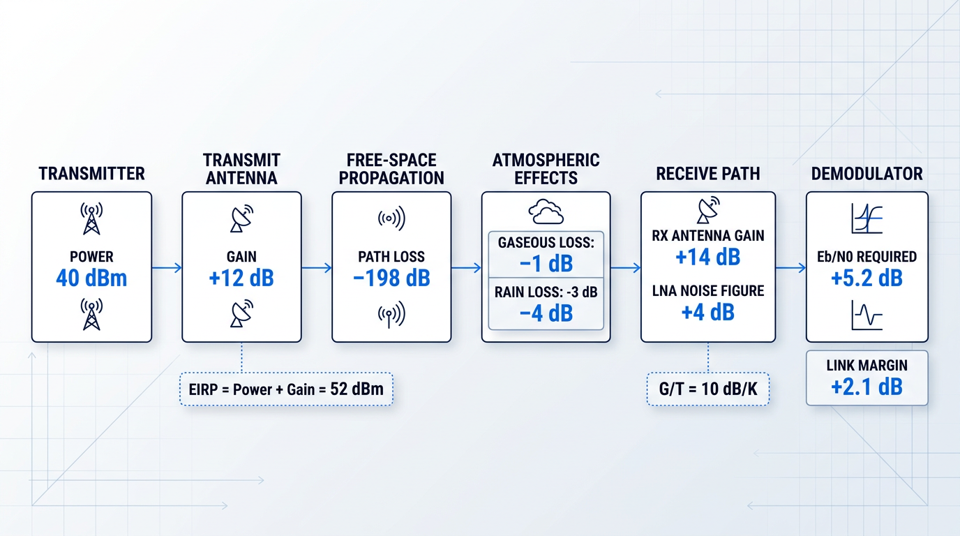
Every component specification discussed in the previous section — LNA noise figure, HPA output power, antenna aperture — ultimately means nothing until it is translated into a number the system either closes or doesn't: the link budget. A link budget is a systematic accounting of every gain and every loss along the signal path, from the transmitter's output through the antenna, across free space, through the atmosphere, into the receive antenna, through the LNA, and down to the demodulator's decision threshold. Its value for procurement is that it makes the relationship between hardware choices and real-world performance explicit and quantifiable.
Without running a link budget, specifying antenna size or amplifier power is guesswork. With one, every trade-off has a number attached to it.
EIRP: The Uplink Figure of Merit
EIRP (effective isotropic radiated power) is the product of the transmitter's output power and the antenna's transmit gain — it is the single figure that characterises how much power the uplink delivers in the direction of the satellite.
Either component can be raised to increase EIRP, but both face hard practical constraints. Amplifier power is bounded by cost, thermal management, and the power flux density limits that satellite operators impose to protect their transponders from overload. Antenna gain is bounded by aperture size, the pointing accuracy the mount can reliably maintain, and platform constraints: a vehicle-mounted terminal simply cannot carry a large dish.
The procurement insight is that EIRP is a system-level figure, not a component-level one. A buyer choosing between a higher-power amplifier and a larger antenna is making the same trade-off from different directions — and the right balance depends entirely on the deployment context.
G/T: The Downlink Figure of Merit
G/T (gain-to-noise-temperature ratio) is the receive-side counterpart to EIRP. The numerator is antenna receive gain; the denominator is the total system noise temperature, which is dominated by the LNA or LNB noise figure but also includes contributions from feedhorn losses, the antenna itself, and sky noise from the atmosphere and ground.
A higher G/T means the receiver can detect weaker signals — which translates directly into the ability to close the link at lower EIRP from the satellite, or to sustain a higher data rate within the same satellite power budget.
For procurement, G/T is the key specification for comparing receive terminals. It captures both the antenna choice and the LNA choice in a single, comparable figure — the number that answers whether a given terminal can receive a given satellite signal at the required quality.
Eb/N0: The Demodulator's Quality Threshold
Eb/N0 (energy per bit to noise density ratio) is the fundamental measure of link quality at the demodulator — the ratio of the energy carried by each information bit to the background noise density against which it must be detected.
The required Eb/N0 is set by the modulation scheme and FEC code rate in use. Higher-order modulation — 16-APSK versus QPSK, for example — demands a higher Eb/N0 to achieve the same bit error rate, because the constellation points are packed more tightly and are harder to distinguish in noise. Stronger FEC (a lower code rate) reduces the required Eb/N0, but at the cost of spectral efficiency, since more of the transmitted bandwidth carries redundancy rather than payload.
Link margin is the buffer between the Eb/N0 the link actually delivers and the minimum Eb/N0 the demodulator requires. It is the headroom the system has before the link degrades below the acceptable error threshold — and it is the number that connects hardware specification to operational availability.
Free-Space Path Loss and the GEO vs LEO Divide
Free-space path loss describes how signal power diminishes with distance and frequency. The relationship follows the inverse-square law: path loss increases with the square of distance and with the square of frequency, so doubling either quadruples the loss in linear terms.
The orbital altitude difference between GEO and LEO makes this relationship operationally significant. A GEO satellite sits at approximately 35,786 km; a LEO satellite in a broadband constellation typically orbits at 550–1,200 km. The resulting difference in free-space path loss is substantial — spanning many orders of magnitude in signal power — and it is the fundamental reason LEO terminals can be smaller and lower-powered than their GEO counterparts.
For procurement, this is not merely background physics. GEO links must overcome far greater path loss, which drives up the EIRP and G/T requirements and, in turn, the antenna aperture and amplifier power the ground terminal must provide. The hardware envelope for a GEO terminal is shaped, first and foremost, by the distance the signal must travel.
Atmospheric Losses: The Frequency-Dependent Wildcard
Beyond free-space path loss, the atmosphere introduces additional losses that must appear in the link budget's loss column. Two categories matter for satellite communications equipment operating across the frequency spectrum.
- Gaseous absorption: Primarily water vapour and oxygen absorption. Relatively predictable and included as a deterministic margin allowance, though it becomes significant at Ka-band and above.
- Rain attenuation: Highly variable fading caused by precipitation. Increases sharply with frequency and is the dominant impairment at Ku, Ka, and higher bands during rain events.
Rain attenuation is not a marginal correction — at higher frequency bands, heavy rain events can produce fade depths large enough to collapse a link that was sized with insufficient margin, and the effect grows more severe as frequency increases.
The critical point is that atmospheric losses are frequency-dependent: lower-frequency bands experience far less attenuation from rain than higher-frequency bands, which means the required link margin reserve grows as frequency increases.
Link Margin Policy: From Rules of Thumb to Statistics
For lower-frequency bands — S-band, X-band, and to a significant degree C-band — atmospheric losses are small and predictable enough that a deterministic margin convention is workable. A fixed margin allowance at these bands is sufficient because the impairments the margin must absorb are bounded and foreseeable.
At Ku-band and Ka-band, this approach breaks down. Rain attenuation is highly variable: it depends on rain rate, rain height, elevation angle, and climate zone, and it is not bounded in the same way. The correct approach at these frequencies is statistical margin design — specifying the link margin required to achieve a target availability percentage (for example, 99.9% of the time in a given climate zone) based on ITU-R rain attenuation models such as Recommendation P.618.
This is not a subtle methodological difference. A buyer specifying a Ka-band system for critical communications who applies a flat deterministic margin will almost certainly undersize the link — and discover the error during the first heavy rain event at the deployment site.
The choice of frequency band directly sets the magnitude and variability of atmospheric losses the link margin must absorb. Operators who treat band selection as a coverage or throughput question alone, and size margin afterwards, routinely find that the margin methodology appropriate for one band is dangerously inadequate for another. The band and the margin approach must be decided together.
Because the margin approach changes fundamentally as frequency increases, frequency band selection is itself a link budget decision — which is exactly where the next section picks up, examining how each band's propagation characteristics translate into real hardware and availability trade-offs.
Frequency Band Trade-offs: Choosing the Right Band
Most frequency band comparisons start with the band and work outward — listing properties, quoting frequency ranges, noting rain fade sensitivity. That approach produces encyclopaedias, not decisions. The right starting point is the operator's application: what data rate is required, what availability guarantee must be met, how large can the terminal be, where will it be deployed, and what regulatory environment governs the spectrum. The answer to those questions determines the band — not the other way around.
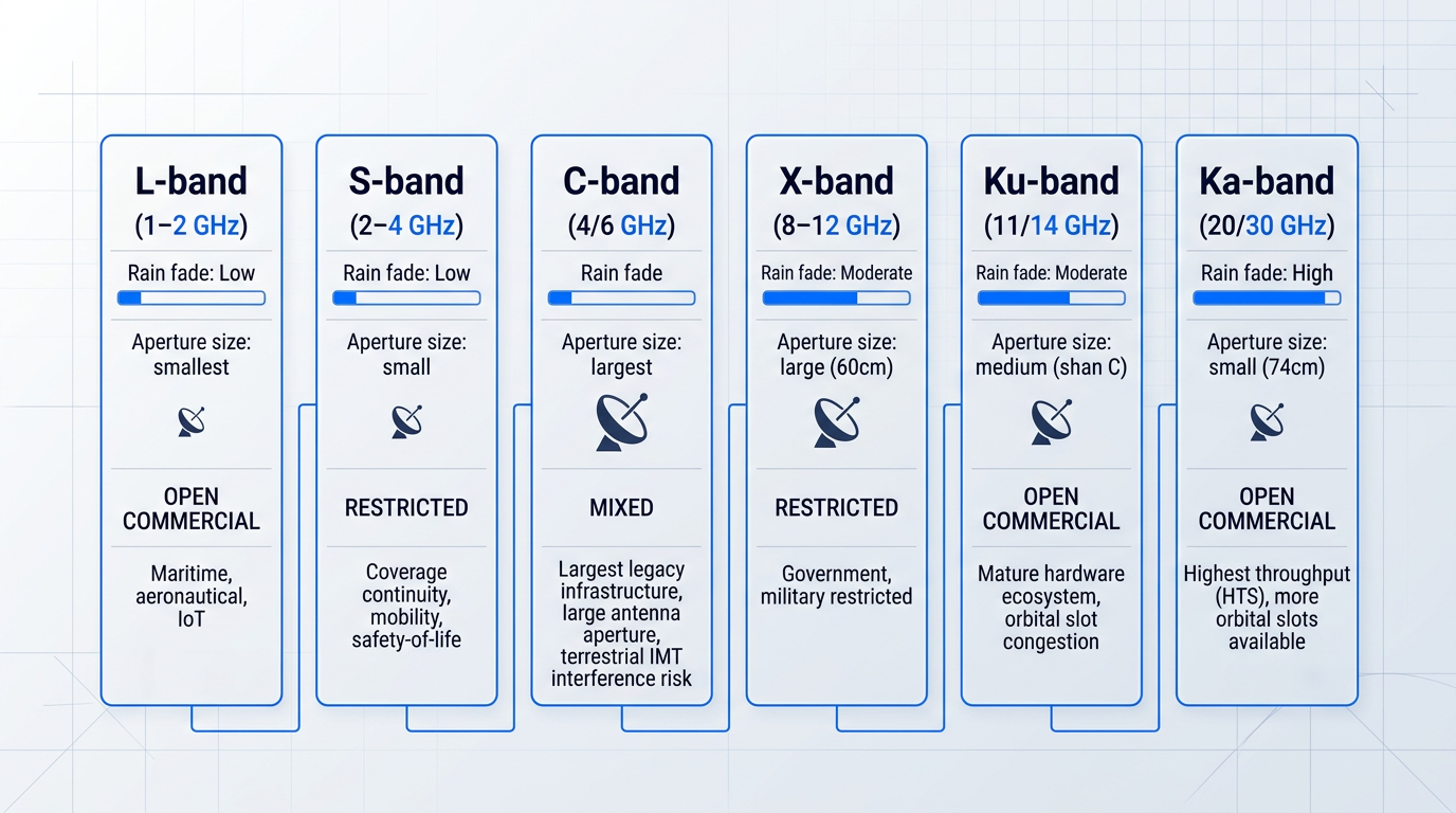
Each band below is treated as a system-level trade-off, not a specification sheet entry — the question throughout is what a given band's characteristics mean for the operator trying to close a link, meet an availability target, and get hardware through a regulatory process.
C-band (4/6 GHz)
Rain-fade resilience is C-band's defining operational advantage: at 6/4 GHz, attenuation due to rain is negligible compared to higher bands, which translates directly into smaller required link margin reserves and consistently high link availability even in tropical or high-rainfall regions.
That resilience is backed by the largest legacy infrastructure in the GEO arc — around 160 geostationary satellites carrying more than 3,000 transponders, representing an investment exceeding USD 30 billion in spacecraft and launch costs alone, with a vast established ground segment on top.
The procurement implication of that installed base is real: wide operator choice, a proven hardware ecosystem, and ground infrastructure that has been in continuous service for decades — all of which reduce integration risk and shorten procurement timelines compared to newer bands.
The constraint is antenna aperture: C-band's longer wavelength requires a larger dish to achieve equivalent gain compared to Ku or Ka, which is a meaningful penalty for applications where terminal size, weight, or mobility is constrained.
An active procurement concern — not a historical footnote — is terrestrial interference from IMT/LTE deployments in the 3.4–3.6 GHz range: ITU studies have confirmed that co-frequency and adjacent-band operations between IMT base stations and FSS earth stations are not compatible in the same geographic area without mitigation, with required separation distances ranging from several kilometres for small cell scenarios up to hundreds of kilometres for macro cell deployments.
Ku-band (11/14 GHz)
Ku-band is the workhorse of commercial satellite communications equipment: it dominates VSAT and direct-to-home broadcasting, with a mature hardware ecosystem and the widest choice of commercial operators of any band.
Smaller terminal apertures than C-band are a meaningful practical advantage — enterprise VSAT deployments and mobility applications where antenna size is constrained benefit directly from the shorter wavelength, which delivers equivalent gain from a physically smaller dish.
Rain-fade sensitivity is moderate: Ku-band is more susceptible than C-band, but in temperate climates the required fade margin is manageable — larger than C-band but substantially smaller than Ka — and the probability distribution of fade events in temperate regions keeps availability targets achievable with ACM and uplink power control, without requiring site diversity in most deployments.
Orbital slot congestion is the structural constraint: Ku-band GEO slots are heavily congested, particularly over Europe, North America, and Asia-Pacific, with around 2,000 satellite networks already notified in the ITU's records — and virtually no new slots available in the most commercially valuable arc positions.
Ka-band (20/30 GHz)
Ka-band's highest throughput potential comes from HTS spot-beam architecture: multiple narrow beams with high frequency reuse factors enable total satellite capacities in the hundreds of gigabits per second — the ViaSat-3 constellation is designed to deliver over 1 Tbps per satellite, and Hughes Jupiter-3 targets 500 Gbps over the Americas, both representing a step-change from conventional wide-beam designs.
The shorter wavelength means a physically smaller antenna achieves the same gain as a larger C- or Ku-band dish — a typical Ka-band consumer or enterprise terminal uses a 74 cm aperture — which is a key driver of Ka-band adoption for both consumer broadband and enterprise VSAT.
Rain attenuation is the defining operational challenge: at 20/30 GHz, fade depths of 15–20 dB or more during heavy rain are possible for a non-negligible percentage of time throughout the year, and clear-sky performance figures are not a reliable guide to actual link availability.
For applications with high availability requirements — emergency communications, defence, financial services — Ka-band requires ACM, site diversity, and uplink power control as non-optional system design elements, not optional add-ons: the required fade margin reserve is substantially larger than for lower bands, and a system designed to clear-sky margins will fail its availability target.
Unlike Ku-band, Ka-band GEO orbital slots are more available — around 1,750 satellite networks are notified at Ka-band in ITU records, but occupancy of the GSO arc remains lower than Ku, which is a significant reason the HTS industry has migrated toward Ka for new capacity.
X-band (8–12 GHz)
X-band is not a commercial option for most buyers: regulatory access is restricted, with the 7.25–7.75 GHz downlink and 7.9–8.4 GHz uplink bands allocated to government and military users, and ITU Radio Regulations footnotes limiting FSS use in these sub-bands accordingly — its inclusion here is to help readers understand why it appears in government and defence procurement contexts.
Rain-fade performance sits between C and Ku: better atmospheric resilience than Ku-band but not as robust as C-band, which combined with its regulatory exclusivity makes X-band attractive for government users who need reliable links in challenging environments without the interference pressure that affects commercial bands.
The Viasat AN/TSC-241 (MMT) is a concrete example of military X-band terminal hardware: a portable flyaway terminal operating across X-, Ku-, commercial Ka-, and military Ka-bands, with a 60 cm aperture, designed for Forward Operating Bases and emergency response operations, and certified to operate over WGS and XTAR satellites — the WGS constellation being the backbone of U.S. DoD satellite communications, providing more than 75% of tactical wideband communications.
L-band and S-band (1–4 GHz)
L-band and S-band operate on a fundamentally different trade-off axis from Ku or Ka: they are not competing on data rate — they serve applications where coverage continuity and mobility matter more than throughput, and where the link must work everywhere, including at low elevation angles and through moderate weather.
The use cases share a common thread: maritime communications, aeronautical connectivity, remote IoT and M2M, and safety-of-life services — all require the link to remain active regardless of geography, which is precisely what L and S-band's lower frequencies and global coverage characteristics deliver.
Iridium's NEXT constellation illustrates how L-band's global coverage characteristics are operationally exploited: service links to users operate in the L-band (1617.775–1626.5 MHz), while feeder links to gateway earth stations use Ka-band (29.1–29.3 GHz uplink, 19.4–19.6 GHz downlink) — the architecture captures L-band's coverage universality at the user terminal while using Ka-band's bandwidth efficiency for the ground network backhaul.
For mobile applications, terminal designs frequently accept lower antenna gain in exchange for omnidirectional or wide-beam coverage — the Inmarsat BGAN Patrol terminal, for example, uses an omnidirectional antenna requiring no pointing, at the cost of data rates capped at around 100 kbps standard IP, while the Iridium Certus 700 service delivers up to 704 Kbps downlink as the fastest commercially available L-band IP data service.
Rain fade is not a meaningful impairment at L and S-band: ITU-R P.679 confirms that signal impairments caused by the troposphere are negligible for frequencies below about 1 GHz, and remain minimal through the S-band range at typical satellite elevation angles — which is precisely why safety-of-life applications gravitate to these bands.
The geographic variability of rain attenuation is the most underappreciated system-level risk in band selection: ITU-R P.618 provides the standard methodology for predicting rain attenuation statistics by geographic region and frequency, taking as its primary input the local rain rate exceeded for 0.01% of an average year — a figure that varies dramatically by location and drives the required fade margin directly.
A Ka-band link designed for 99.99% annual availability requires a fade margin of at least 12 dB at a site in southern England, but at least 18 dB at a site in Attica, Greece — for the same hardware configuration — because the rain rate at the 0.01% exceedance level is approximately 20 mm/h in the UK versus 65–70 mm/h in Greece.
The availability ceiling of a Ka-band link is set by the probability distribution of rain attenuation events across the deployment region, quantified per ITU-R P.618 — not by clear-sky link margin. The same hardware that meets a 99.99% availability target in temperate Europe may fall short of 99% in a high-rainfall tropical deployment without additional fade mitigation.
Regulatory access varies significantly by band and jurisdiction, and this is a procurement-relevant fact: X-band FSS is restricted to government and military users under ITU Radio Regulations; Ka-band HTS systems benefit from the High-Density FSS (HDFSS) framework under ITU RR No. 5.516B, which identifies specific Ka-band frequency ranges for high-density applications and enables simplified coordination procedures — allowing Ka-band VSAT terminals to be deployed at scale without individual site licensing in many jurisdictions, provided they operate within the exclusive Ka-FSS spectrum (27.5–30 GHz uplink, 19.7–20.2 GHz downlink).
National regulators implement ITU allocations differently: a band that is freely licensed in one jurisdiction may require individual coordination in another, and the 3.4–4.2 GHz range that underpins C-band FSS has been subject to partial reallocation for IMT in multiple Region 1 and Region 2 countries — making national regulatory due diligence essential for any international deployment.
Band selection is ultimately a system engineering decision, not a frequency preference: the operator's data rate requirement, availability guarantee, terminal size and mobility constraints, geographic deployment region, and regulatory environment together determine which band can close the required link — and a buyer who selects Ka-band for its headline throughput without modelling the rain attenuation statistics of the deployment region has made a hardware decision without doing the system engineering.
With a band selected on the basis of those application requirements, the next challenge is integrating the hardware for that band into a real deployment — which means confronting the IF/RF chain design, protocol compatibility, and legacy infrastructure constraints that are the subject of the next section.
Integration Complexity and Legacy Compatibility
Selecting the right components is the part buyers spend most of their time on. Getting them to work together is where deployments actually succeed or fail — and it is the step that no datasheet prepares you for.
The IF/RF signal chain — from the modem's baseband output, through frequency converters, along the intra-facility cabling, to the antenna feed — is best understood as an integration architecture, not a list of parts. Every interface in that chain is a potential degradation point: impedance mismatches, connector quality, cable losses, and reference clock alignment all affect end-to-end system performance in ways that are invisible when each component is evaluated in isolation.
L-Band IFL and the Legacy IF Transition
The industry has largely moved from 70/140 MHz IF to L-band IFL (intra-facility link, typically 950–1450 MHz or wider) as the standard connection between indoor and outdoor units.
The practical advantage of L-band IFL is significant: the LNB or BUC can be located at the antenna feed, with a single coaxial cable carrying both the IF signal and DC power to the LNB, reducing the number of frequency conversion stages and the associated cable loss.
Legacy sites still running 70/140 MHz IF face a real compatibility constraint when integrating newer modems or outdoor units — the IF frequency must be matched consistently across the entire chain, and modern equipment increasingly assumes L-band as the baseline.
The upgrade decision for a legacy site comes down to two paths: retrofit IF conversion equipment to bridge the old and new standards, or replace the outdoor unit with one that natively supports L-band IFL. The right choice depends on the age of the existing infrastructure and the planned service life of the new equipment — neither path is trivial.
Waveform and Protocol Compatibility
DVB-S2X is the dominant commercial waveform standard for broadband SATCOM, extending DVB-S2 with higher spectral efficiency, finer modulation granularity, and support for very low SNR operation — capabilities that matter directly for Adaptive Coding and Modulation (ACM) performance across variable link conditions.
For government and military procurement, the relevant waveform standards include STANAG 4486 (and its associated EBEM waveform) for NATO wideband satellite communications, and MIL-STD-188-182/183 for UHF DAMA (Demand Assigned Multiple Access) channels — both of which impose specific modem and network management requirements that must be confirmed before any procurement commitment.
The procurement verification point that buyers most commonly miss is this: waveform support must be confirmed across the modem, the hub, and the network management system — not just at the terminal. A modem that supports DVB-S2X is operationally useless if the hub it connects to only supports DVB-S2, or if the NMS cannot configure S2X parameters.
Individual component datasheets will each show a supported waveform list. None of them will tell you whether the waveform versions align end-to-end. System-level waveform verification — modem, hub, and NMS tested together before deployment — is the only way to catch this class of incompatibility before it becomes a live network outage.
Looking further ahead, the DIFI standard (Digital IF Interoperability, developed under IEEE ISTO) defines a digital IF signal over IP between the modem and the RF chain, replacing the analogue IF coaxial connection entirely. Industry demonstrations have established DIFI as a credible direction for open-architecture ground systems, enabling waveform-agnostic digital interfaces that reduce proprietary lock-in at the modem-to-BUC boundary.
DIFI is not yet universally adopted across the industry, but its trajectory is clear: it represents the path toward software-defined signal processing across the full RF chain, and buyers specifying long-lifecycle ground systems should ask suppliers where their roadmap sits relative to the standard.
Antenna Controller Integration and OpenAMIP
In mobility applications — maritime, aeronautical, and land mobile — the antenna controller must communicate continuously with the modem to manage beam pointing, network entry, and handover between satellite coverage zones.
OpenAMIP (Open Antenna Motion Interface Protocol) is the open standard that defines this interface, enabling interoperability between antenna systems and modems from different manufacturers. Its adoption within aviation SATCOM installation standards marks a concrete standardisation milestone: specifying OpenAMIP compliance in a procurement locks in interoperability and avoids being bound to a single antenna-modem vendor pairing for the life of the platform.
Common Integration Failure Points
Experienced integrators encounter the same failure modes repeatedly — and none of them appear on individual component datasheets. They only surface when the full system is assembled and tested.
- Noise figure mismatch: The modem's input noise figure must be compatible with the LNA's output noise temperature; a mismatch degrades system G/T below what the link budget assumed.
- Polarisation misconfiguration: Linear vs circular polarisation, and RHCP vs LHCP, must be consistent across the LNB, modem, and network settings — a mismatch causes severe signal loss.
- Inadequate cable screening: Poor coaxial screening allows interference ingress, particularly at L-band IFL where the same cable carries both the IF signal and DC power to the LNB.
- Reference clock incompatibility: Many modems and BUCs require a shared 10 MHz reference clock; mismatches between components cause frequency instability and demodulation failures under load.
- IF frequency mismatch: When mixing equipment generations, the IF centre frequency assumed by the modem and the outdoor unit may differ, producing a link that appears to connect but carries no usable signal.
What these failure modes share is that they are system-level properties — they emerge from the interaction between components, not from any single unit's specification. This is precisely why in-house engineering capability at your supplier matters: a reseller cannot diagnose a noise figure mismatch or a reference clock conflict in the field.
Multi-orbit terminals — capable of switching between GEO, MEO, and LEO constellations — sit at the leading edge of this integration complexity. Managing handovers across different network management systems and hosting multiple waveform stacks simultaneously demands software-defined modem architectures and antenna systems with dynamic beam steering; the integration burden is substantial and should be factored into any multi-orbit procurement.
Software-defined modems offer a meaningful hedge against both integration complexity and protocol obsolescence more broadly: hardware that can host multiple waveforms and switch at runtime — DVB-S2X for a commercial GEO network today, STANAG 4486 for a military network, a proprietary LEO waveform as constellations mature — reduces the risk of being locked to a specific network or constellation architecture as the market evolves.
Getting the integration architecture right in a controlled environment is a necessary first step, but it is not the last one. The next challenge is ensuring that the validated system remains stable when deployed in the conditions it was actually bought for — which is where ruggedisation and environmental qualification take over.
Ruggedisation and Environmental Requirements for SATCOM Hardware
A satellite communications terminal that performs flawlessly in a lab can fail within weeks of field deployment — not because the link budget was wrong, not because the integration was poorly executed, but because the hardware was never built to survive the environment it was placed in. "Ruggedised" is not a binary property stamped on a product; it is a spectrum, and the gap between commercial-grade equipment optimised for a controlled server room and hardware genuinely qualified for operational field conditions is where procurement decisions go expensively wrong.
Commercial-grade satellite communications equipment is designed to operate within tight environmental tolerances: stable temperatures, low humidity, minimal vibration. Field deployments offer none of those controls. Mechanical shock, sustained vibration, thermal cycling between arctic cold and tropical heat, moisture ingress, salt-laden air, and abrasive dust are not edge cases — they are the baseline conditions for any ground-mobile, maritime, or airborne SATCOM deployment.
Key Environmental Standards and What They Actually Test
MIL-STD-810H (2019) is the primary US DoD environmental test method standard for military equipment. It is critical to understand what it is and, equally, what it is not: MIL-STD-810H is a test standard, not a design specification and not a certification scheme. It defines the test procedures and pass/fail criteria for a defined set of environmental stress conditions — it does not certify products, and it does not mandate which tests must be applied to any given equipment type.
The practical implication of this distinction is significant for procurement. A supplier can truthfully claim their product is "designed to MIL-STD-810" without having subjected a single unit to a single test method. The correct procurement question is not whether a product meets MIL-STD-810, but which specific test methods were applied, to which revision, on which hardware configuration, and are the documented test reports available.
MIL-STD-810H covers a comprehensive environmental stress profile. The test methods most directly relevant to field-deployed SATCOM hardware are listed below, with their method numbers confirmed against the current revision.
- High/Low Temperature (501.7 / 502.7): Tests equipment operation across the full temperature range, exposing thermal shutdown risk and component degradation under sustained heat or cold.
- Temperature Shock (503.7): Rapid cycling between temperature extremes; reveals mechanical fatigue in solder joints, connectors, and seals caused by differential thermal expansion.
- Humidity (507.6): Sustained high-humidity exposure; tests corrosion of internal conductors, degradation of insulation, and moisture ingress through seals and cable entries.
- Salt Fog (509.7): Evaluates corrosion resistance of protective coatings and enclosure materials; essential for maritime and coastal deployments.
- Sand and Dust (510.7): Blowing dust (fine particles) and blowing sand (coarse particles) tested separately; assesses ingress through gaps and abrasion of exposed surfaces.
- Vibration (514.8): Covers multiple vibration profiles — basic transportation, minimum integrity, and platform-specific categories for ground mobile and tracked vehicles.
- Shock (516.8): Includes functional shock (equipment must continue operating after the event) and transit drop (equipment must survive handling without damage).
- Immersion (512.6): Tests equipment survival after submersion; relevant for manpack and portable terminals that may be exposed to water crossings or heavy rainfall.
- Low Pressure / Altitude (500.6): Tests operation and storage at altitude; relevant for airborne installations and high-altitude ground deployments.
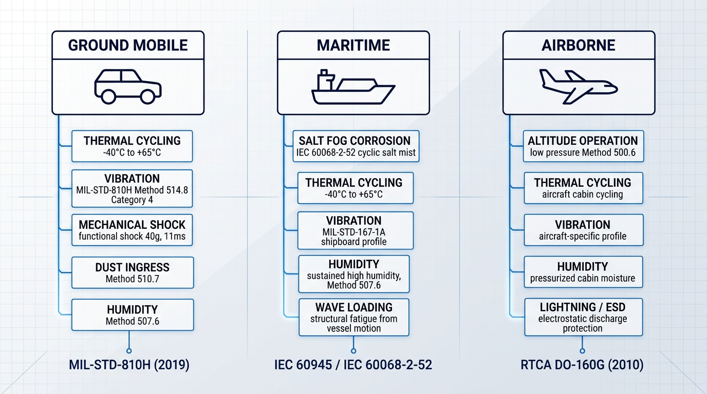
To illustrate what verified MIL-STD-810 compliance looks like in practice: the L3Harris SPARTIN universal antenna kit datasheet lists specific method numbers and procedures for each test — Method 501.7/502.7 for temperature (operating range -40°C to +65°C), Method 514.8 for vibration (including Category 4 ground mobile and Category 24 minimum integrity profiles), Method 516.8 for functional shock and transit drop, and Method 509.7 for salt fog, among others. That level of specificity is the baseline a buyer should expect from any supplier claiming environmental qualification.
The L3Harris A3M resilient waveform modem family similarly lists MIL-STD-810G compliance with a 40g, 11 ms functional shock specification and distinct vibration profiles for ground mobile, tracked vehicle, and mission/field transportation — a useful reminder that vibration qualification is not a single number but a platform-specific profile.
IP ratings under IEC 60529 address a narrower but commonly misunderstood dimension of environmental protection: enclosure resistance to solid particle and liquid ingress. The IP code is composed of two numerals — the first rates protection against solid objects (0 to 6, where 6 is dust-tight), the second rates protection against liquids (0 to 9K, where 9K indicates resistance to high-pressure, high-temperature water jets).
IP67 — dust-tight and protected against temporary immersion in water — is a common specification floor for military SATCOM terminals. IP69K adds resistance to high-pressure water jets, relevant for equipment subject to wash-down procedures in maritime or vehicle-mounted applications. The L3Harris XL Onboard 85M lists IP65 for its control unit and IP54 for the radio body, illustrating that different sub-assemblies within the same system may carry different ingress ratings.
An IP67 rating confirms dust-tight and immersion-resistant enclosure sealing — it says nothing about shock tolerance, vibration resistance, or thermal performance. MIL-STD-810 addresses those. Both are necessary for genuine field qualification; neither substitutes for the other.
For airborne SATCOM equipment, the applicable environmental test framework is RTCA DO-160G, published in 2010 and recognised by the FAA under Advisory Circular AC 21-16G as well as by aviation regulatory authorities worldwide. DO-160G covers vibration, temperature and altitude, humidity, waterproofness, sand and dust, salt fog, icing, EMI, lightning, and electrostatic discharge — the full environmental and electromagnetic regime an aircraft-installed avionics unit must survive.
A separate standard exists for airborne equipment because the vibration spectrum, altitude range, and thermal cycling profile of an aircraft installation are materially different from ground or maritime deployments, and aviation certification authorities require demonstrated compliance with DO-160G for installed avionics. DO-160G is the current version; a revision, DO-160H, is in development and expected to be published in 2026. Buyers specifying airborne SATCOM terminals should confirm which revision a product has been tested to.
MIL-STD-461 governs electromagnetic interference compliance for military equipment, covering both conducted and radiated emissions and susceptibility. The L3Harris AN/PRC-167 manpack and A3M modem family both list MIL-STD-461 compliance. For commercial equipment deployed in non-military contexts, the equivalent requirements are FCC Part 15 in the United States and CE marking under the EU Electromagnetic Compatibility Directive.
EMI compliance is not purely a regulatory matter. A SATCOM terminal that radiates interference beyond its specified limits can degrade co-located navigation, communications, or sensor systems — a serious concern in shipboard and vehicle installations where multiple transmitters and receivers share a confined space. Equally, a terminal with insufficient susceptibility margin will suffer degraded link performance when co-located equipment radiates. Both dimensions of EMI performance — emissions and susceptibility — need to be specified and verified.
Deployment-Specific Environmental Requirements
Operating temperature range is one of the most consequential specifications for field-deployed satellite communications equipment, and one of the most frequently underspecified. Military-grade hardware commonly targets an operating range of -40°C to +60°C or +71°C, with storage temperatures extending further. The L3Harris AN/PRC-167 manpack specifies operating temperatures of -40°C to +60°C and storage to +85°C; the SPARTIN antenna adapter operates from -40°C to +65°C with storage to +85°C.
The significance of temperature range extends well beyond the obvious risk of thermal shutdown. Repeated thermal cycling between operating extremes causes mechanical fatigue in solder joints and connector interfaces — a failure mode that accumulates invisibly over time and manifests as intermittent link loss rather than a clean failure. Thermal management design also affects component longevity directly: a terminal running at the top of its thermal envelope continuously will age faster than one with adequate heat dissipation margin.
Vibration qualification requires careful attention to which platform profile was tested, not merely whether a vibration test was conducted. MIL-STD-810H Method 514.8 includes multiple vibration categories — Category 4 covers basic transportation and ground mobile vehicles, while tracked vehicles impose a distinctly different vibration spectrum with higher energy at lower frequencies. Shipboard installations are governed by MIL-STD-167-1A for mechanical vibration, which reflects the propulsion and machinery-induced vibration profile of naval vessels.
The distinction between functional shock and transit drop is equally important. Functional shock — tested under Method 516.8 Procedure I — requires the equipment to continue operating correctly after a defined shock event (for example, a 40g, 11 ms half-sine pulse, as specified for the A3M modem). Transit drop tests that the equipment survives handling and transport without physical damage. These are separate test profiles with different engineering implications: a terminal that passes functional shock may still fail transit drop if its external connectors or display are poorly protected.
Maritime deployments impose a distinct combination of stresses that no single standard fully captures. Above-deck antenna units face continuous exposure to salt fog, UV radiation, wave spray, and temperature cycling; below-deck electronics face sustained high humidity, vibration from vessel motion, and ambient salinity in the ship's air. The maritime framing standard for shipborne equipment is IEC 60945, which defines environmental and EMC test requirements for exposed and protected equipment categories. Corrosion resistance testing to IEC 60068-2-52 (cyclic salt mist) is the specific test method for salt-laden atmosphere durability.
Maritime SATCOM deployments typically require separate environmental specifications for the outdoor unit (antenna, BUC, and LNB assembly) and the indoor unit (modem and controller). An IP rating for the above-deck antenna enclosure must be evaluated alongside corrosion resistance and structural integrity under wave loading — IP67 alone does not address the multi-year salt fog exposure or the mechanical fatigue from continuous hull-induced vibration that a masthead antenna installation will accumulate.
Verifying Environmental Claims: What to Ask Suppliers
The gap between a product that is genuinely environmentally qualified and one that merely claims to be is not always visible in a datasheet. "Meets MIL-STD-810" without further detail is a marketing statement, not a technical specification. The buyer's job is to move the conversation from claims to evidence.
The following questions form a practical due diligence checklist for any supplier making environmental qualification claims about their satellite communications equipment.
- Which specific test methods were applied?: Require the supplier to list method numbers and procedures — e.g. Method 514.8 Category 4, not simply "vibration tested to MIL-STD-810."
- To which revision of the standard?: MIL-STD-810 has been revised multiple times; the current revision is 810H (2019). Method numbering changed between revisions — verify the revision tested.
- What were the pass/fail criteria?: A test is only meaningful if the acceptance criteria are defined. Ask what constitutes a pass for each method and whether the product met those criteria.
- Are test reports available?: Documented test reports from an accredited laboratory are the gold standard. Reports should identify the hardware configuration tested and the date of testing.
- Was production hardware tested?: Qualification on a hand-built prototype does not guarantee production units will perform identically. Confirm testing was conducted on production-representative hardware.
- Does the vibration profile match your platform?: A product qualified for ground mobile vehicles may not be appropriate for tracked vehicles or shipboard installation — verify the specific vibration categories tested.
These questions apply equally to IP ratings, DO-160G compliance for airborne equipment, MIL-STD-461 EMI qualification, and maritime standards such as IEC 60945. In each case, the principle is the same: a named standard cited without documented test results is an unverified claim, and unverified claims carry real operational risk when the equipment is deployed in conditions it was never actually tested to survive.
Knowing which questions to ask is only part of the picture. The next consideration is how to evaluate whether the supplier standing behind those answers has the engineering depth, production quality, and lifecycle support infrastructure to back them up — which is what the following section addresses.
Evaluating Manufacturers: What the Datasheet Does Not Tell You
By this point in a procurement evaluation, most buyers can read a datasheet competently — they understand G/T, EIRP, phase noise, and environmental ratings. What the datasheet cannot tell them is whether the organisation behind it can support a programme over a 10–15 year lifecycle, diagnose an integration failure that falls outside the manual, or maintain spares availability when a key subassembly reaches end-of-life. Those questions require a different kind of interrogation.
OEM Manufacturers vs Resellers and Importers
The OEM manufacturer vs reseller distinction is the most structurally important question a buyer can ask, and it is rarely answered directly on a supplier's website. An OEM designs and builds its own hardware; a reseller sources, rebrands, or distributes equipment manufactured elsewhere — and that structural difference has direct consequences for every dimension of lifecycle support.
Only the organisation that built the hardware understands it deeply enough to diagnose non-standard integration problems, adapt it to requirements that were not anticipated at manufacture, or guarantee continuity of spares when the upstream supply chain shifts. A reseller is entirely dependent on its upstream manufacturer for all three — and if that manufacturer discontinues the product or changes the design, the reseller has no remedy to offer.
In-House Engineering Capability and Lifecycle Support
Genuine in-house engineering capability goes well beyond having a technical support team. It means the supplier can engage with the buyer's specific deployment context, identify integration issues that do not appear in any manual, and modify hardware to meet requirements that were not part of the original design brief. The practical test is simple: can this supplier solve a problem they have never seen before, or are they limited to problems the documentation already answers?
Lifecycle support has three distinct dimensions that buyers should evaluate separately: spares availability over the programme life, software update continuity (including waveform and protocol updates as standards evolve), and the duration of committed technical support. A supplier who offers a three-year product warranty but discontinues the product after four years leaves a programme with no path to repair or replacement at a critical point.
According to a DoD Inspector General report, more than 50% of the life-cycle cost of DoD weapon systems is spent on spare parts. For SATCOM hardware programmes running 10–20 years, lifecycle support is not a secondary procurement consideration — it is the dominant cost driver.
Component-level obsolescence is a specific and underappreciated risk in long-lifecycle programmes. SATCOM hardware that enters service today may still be in operational use in 2040 — by which point the component supply chains that supported the original design will have changed substantially. Buyers should ask whether the supplier maintains inventory of critical subassemblies, provides advance notice of discontinuance, and operates a documented obsolescence management process — not simply whether they offer a support contract.
Certification and Regulatory Compliance
CE and UKCA marking covers electromagnetic compatibility and safety requirements — it is not a statement about product performance or fitness for purpose. A buyer who treats regulatory marking as a proxy for overall product quality is conflating two entirely separate questions. The marking tells you the manufacturer believes the product meets applicable EMC and safety directives; it says nothing about link margin, thermal stability under load, or whether the unit will perform to its stated EIRP at the edge of its temperature range.
For US market equipment, FCC equipment authorisation operates through two main procedures. Certification — the more rigorous process — is required for intentional radiators (transmitters) and involves third-party testing by an FCC-recognised Telecommunication Certification Body, with the result posted on the FCC's public equipment authorisation database. Supplier's Declaration of Conformity (SDoC) is a self-declaration procedure used for lower-risk devices such as unintentional radiators; it does not require an FCC ID and is not listed in the public database. For buyers procuring in European regulatory environments, ETSI harmonised standards — including EN 301 428 for VSAT earth stations operating in the Ku-band — define the technical requirements against which earth station equipment is assessed under the Radio Equipment Directive.
The practical risk is that certification claims are easy to make and difficult to verify without knowing where to look. Buyers should not accept a claim of FCC certification at face value.
- Request the FCC ID: Ask for the specific FCC ID number and verify it directly against the FCC's public equipment authorisation database at fcc.gov/oet/ea/fccid.
- Confirm the procedure used: Establish whether authorisation was by Certification (third-party tested, listed in FCC database) or SDoC (self-declared, no FCC ID), and verify this matches the device class.
- Request the Declaration of Conformity: For CE or UKCA marked equipment, ask for the DoC and check that it references the specific directives and harmonised standards applicable to the product.
- Check notified body involvement: Where a notified body was required for conformity assessment, verify the body's identification number and confirm its appointment for the relevant directive.
The same verification discipline that applies to environmental qualification claims — asking for documented evidence rather than accepting marketing assertions — applies equally to regulatory compliance. Certification and marking are verifiable; a supplier who cannot or will not provide the documentation to support verification warrants scrutiny.
Export Control Compliance: ITAR and EAR
Export control is one of the most underestimated procurement risks in SATCOM hardware, particularly for buyers operating in government, defence, or international supply chains. ITAR controls under USML Category XV continue to apply to defence-grade SATCOM hardware — spacecraft, ground control systems, and parts specifically designed for military satellite functions remain on the US Munitions List and require State Department licensing for export.
A material change occurred in 2014, when the US Departments of Commerce and State published rules transferring most commercial satellite items from USML Category XV to the Commerce Control List under new ECCNs 9A515, 9B515, 9D515, and 9E515. Items transferred included commercial communications satellites without classified components, ground control systems specially designed for telemetry, tracking and control of those spacecraft, radiation-hardened microelectronics, and parts and components of satellite bus and payloads not listed on the USML. The practical implication for buyers: the jurisdiction and classification of a given piece of satellite communications equipment is not always obvious, and international procurement, re-export, and supply chain due diligence all require the ECCN classification to be verified with the supplier. Buyers engaged in international procurement should obtain independent legal advice — this is a legal and regulatory area where awareness is necessary but professional guidance is essential.
Government Procurement Processes: DoD-Specific Requirements
For US Department of Defense buyers, several process requirements apply before SATCOM terminals can be fielded or connected to DoD networks. Under CJCSI 6250.01E, all DoD SATCOM needs must be validated through the SATCOM Database (SDB), maintained by DISA through the Joint SATCOM Panel Administrator — and DISA's Technical Support Branch will not process a commercial satellite requirement without a valid SDB number or an approved waiver.
Once the SDB number is in place, customers submit a Satellite Access Request (SAR) through their Regional SATCOM Support Centre to request satellite access for a mission, and a Gateway Access Request (GAR) when landing at a DoD teleport. Separately, terminal certification under DoDI 8330.01 — administered through JITC — is a prerequisite for connection of IT and NSS to any DoD network, requiring interoperability testing against joint requirements before fielding. Buyers procuring hardware for DoD programmes should factor these certification timelines into programme schedules from the outset.
Evaluating Technical Support Structures
Support contracts are rarely equivalent, even when they carry similar labels. The tiered support model is the most useful framework for understanding what a buyer is actually purchasing. Tier 1 is front-line phone or email support working from a knowledge base; Tier 2 involves more experienced technical staff capable of diagnosing non-standard problems; Tier 3 means the engineers who designed the hardware are engaged. For complex field deployments, only Tier 3 access provides the depth needed to resolve integration failures that fall outside documented scenarios.
For classified programmes, the requirement for cleared engineering staff is an additional procurement constraint that significantly narrows the supplier pool. Beyond clearance, the practical distinction between phone-in support and on-site engineering engagement is material: a supplier who can deploy an engineer to a remote or austere location is categorically different from one who can only provide remote diagnostics, regardless of how both describe their support offering.
The supplier evaluation criteria covered in this section — OEM depth, lifecycle commitment, obsolescence management, and genuine engineering access — become especially consequential as the hardware landscape shifts. The next section examines how optical links and LEO mega-constellations are introducing new hardware requirements over the coming decade, and why the configurability and standards adaptability of a supplier's engineering base will matter as much as any specification on today's datasheet.
Optical Links and LEO Constellations: Hardware Implications
The RF spectrum does not expand. As covered in the frequency band discussion earlier in this guide, C and Ku bands are congested, Ka is under growing pressure, and frequency reuse has limits that physics enforces regardless of regulatory creativity. For buyers specifying satellite communications equipment with a five-to-ten-year operational horizon, two developments are now materially reshaping what hardware to specify and why: free-space optical ground links that bypass the RF spectrum ceiling entirely, and LEO mega-constellations that impose fundamentally different antenna, pointing, and handover requirements on ground terminals.
Free-Space Optical Ground Links
A free-space optical (FSO) link transmits data using a laser beam propagating through free space rather than through a guided medium such as fibre. For satellite ground links, the preferred wavelength is 1550 nm — in the C-band optical window — because atmospheric attenuation at this wavelength remains below 2 dB at low elevation angles, abundant off-the-shelf components exist from the terrestrial fibre industry, and the eye-safety margin is substantially higher than at 1064 nm.
The data-carrying capacity of optical links is qualitatively different from RF, not incrementally better. A 1550 nm laser operating at 200 THz bandwidth can theoretically support data rates orders of magnitude beyond what a 2000 MHz microwave link can carry — and it does so without requiring licensed spectrum, eliminating the regulatory costs and coordination obligations that come with every RF frequency assignment.
The principal challenge for ground-to-space optical uplinks is the atmosphere. When a laser beam originates at a ground station, it traverses the full depth of the turbulent atmosphere immediately — unlike a downlink, which only encounters atmospheric effects in the final 30 km of its path. This means uplinks suffer more severely from scintillation (intensity fluctuations caused by refractive-index variations in atmospheric eddies), beam wander, and wavefront distortion, all of which can cause deep signal fades and degrade pointing accuracy.
Two architectural mitigations are standard for managing uplink outage risk. Aperture diversity uses multiple transmit apertures or emitter arrays so that independent beams average out scintillation-induced fades at the satellite receiver. Site diversity distributes ground stations across geographically separated locations with uncorrelated weather patterns, so that cloud cover at one site does not interrupt the link — a satellite can receive from whichever station has a clear sky.
- Optical terminal: Telescope-class transmit/receive optics that collimate the laser beam to diffraction-limited divergence for long-range propagation to the satellite.
- ATP system: Acquisition, tracking, and pointing subsystem — maintains sub-microradian beam alignment with a moving satellite despite platform vibration and atmospheric tilt.
- Uplink amplifier: Boosts laser output to the power levels needed to close the link budget through atmospheric loss; typically an erbium-doped fibre amplifier at 1550 nm.
- Atmospheric compensation: Adaptive optics or multi-beam transmit diversity to pre-correct wavefront distortion and reduce scintillation-induced fade depth on the uplink.
- Site diversity network: Geographically distributed ground stations with coordinated switching, ensuring cloud cover at any single site does not interrupt the optical uplink.
Each of these elements interacts with the others in ways that matter for procurement. The uplink amplifier's output power must be matched to the link budget, which is itself a function of aperture size, pointing loss, and atmospheric margin. The ATP system's acquisition time and tracking bandwidth set constraints on how quickly a handover between ground stations can occur. And the amplifier's modulation capability determines which beacon and data waveforms the ground station can support — which brings the standards question directly into the hardware specification.
Optical communication standards for satellite ground links are still evolving. CCSDS 141.0-B-1 (the Blue Book for optical communications physical layer, published 2019) remains under active revision, with draft updates in circulation. The Space Development Agency's OCT Standard has progressed through multiple versions — v2.1.2 covered Tranche 0 interoperability, v4.0.0 introduced additional waveforms for longer-range links — and a 2024 SDA RFI explicitly solicited industry feedback on future waveform directions for Tranche 3 and beyond.
The procurement principle that follows is straightforward: a ground station uplink amplifier should be software-definable, not fixed-function. The amplifier that can be reconfigured across wavelength, modulation waveform, and beacon standard — without requiring new hardware — is the one that protects a multi-year programme against standards drift.
Woodrow Scientific's erbium-doped fibre amplifier (EDFA) is a concrete example of this category of hardware. Its defining design choice is single-beam beacon and data: the tracking beacon and uplink data are nested within one amplified beam, with amplitude modulation carrying the tracking tone low and the data signal above it. This architecture simplifies the optical train and eliminates the alignment and power-splitting overhead of a two-beam approach.
The amplifier is configured across both hardware and software layers to the specific ground station. On the hardware side, this means band selection (C-band, L-band, or dual-band from a single unit), output power (10 W standard, higher on request), direction, emitter array configuration (2- or 4-emitter arrays for site and emitter diversity), and an external optical input port for amplifying third-party transmitters at OOK rates up to 20 Mbps. On the software side, Woodrow Scientific's Modulation-on-Demand applies software-selectable amplitude modulation throughout the link — square or sinusoidal waveforms, adjustable frequency and modulation index — and is switchable to CCSDS or SDA standards at high power across C and L-band.
Woodrow Scientific (founded 2012) designs, builds, qualifies, and supports the amplifier entirely in-house on patented technology, with engineering expertise rooted in Southampton's Optoelectronics Research Centre — the institution where the EDFA was originally developed. Many suppliers in this space are resellers or importers rather than manufacturers, which means limited ability to adapt a product at either the hardware or software layer; the practical consequence of working with an in-house manufacturer is direct engineering support and no intermediary between the buyer and the people who built the product. The amplifier is CE and UKCA certified and manufactured in the UK.
The SDA issued a fresh RFI on optical waveforms in 2024, selecting a burst-mode waveform and planning to add further waveform types to OCT Standard v4.0.0. A ground station uplink amplifier purchased before that version was finalised — and locked to an earlier fixed-function spec — would already require hardware changes to remain compliant. Configurability is not a future-proofing aspiration; it is a response to a standards cycle that has already turned over multiple times.
LEO Mega-Constellations and Antenna Requirements
GEO satellites are fixed relative to the ground — a dish antenna points once during commissioning and stays there. LEO satellites are in continuous motion across the sky, passing overhead in minutes. This single difference cascades into a set of hardware requirements that have no equivalent in GEO-only deployments: ground terminals must either electronically steer their beam continuously or fast-slew mechanically, and they must manage handover between successive satellites as each one passes beyond the horizon.
The principal LEO mega-constellation programmes — Starlink (SpaceX), OneWeb (Eutelsat), and Amazon Kuiper — each operate or are building constellations of hundreds to thousands of satellites, predominantly in Ku and Ka bands. Handover between satellites as each passes overhead introduces beam management complexity and, if not handled in hardware and software, brief connectivity interruptions that fixed-dish GEO deployments simply do not experience.
Electronically steered flat-panel antennas — phased array terminals — are the enabling technology for LEO user terminals. By controlling the phase of signals across an array of antenna elements, they steer the beam without any moving parts, enabling rapid satellite tracking and seamless handover. The Hughes HL1100, engineered for the OneWeb Ku-band constellation, illustrates the trade-offs: its electronically steered antenna covers 54 degrees elevation from zenith with full 360-degree azimuth and a pointing error no greater than 0.75 degrees, but draws 130 W typically — considerably more than a comparable parabolic dish.
Phased array terminals offer a lower profile and no moving parts to fail, but carry a higher unit cost than a parabolic reflector of equivalent aperture. For fixed enterprise or government sites where a GEO parabolic dish already closes the link, the phased array's advantages are less compelling; for mobile or expeditionary platforms where continuous LEO tracking is required, there is no practical alternative.
Terminals capable of connecting across both GEO and LEO networks offer resilience and orbit-switching flexibility, but they introduce significant integration complexity and cost. Multi-orbit flat-panel terminal programmes have so far been adopted primarily in high-value defence and government applications — a near-term constraint on broader adoption, though not a permanent one as integration costs continue to fall.
The spectrum picture for LEO constellations creates additional obligations for ground station operators. Under the ITU Radio Regulations framework, spectrum allocations carry either primary or secondary status: secondary-service stations must not cause harmful interference to primary-service holders and cannot claim protection from them. LEO constellation operators working within already-allocated Ku and Ka bands face coordination obligations that grow more complex as the number of constellations sharing those bands increases. This pressure is accelerating interest in V-band — which sits directly above Ka and offers more available bandwidth — and in optical links, which require no spectrum filing whatsoever.
For buyers specifying hardware today, the procurement implication is not that optical links or LEO terminals must be deployed immediately. It is that hardware specified for five-to-ten-year operational horizons should be selected with this trajectory in mind: equipment with open interface standards, software-configurable control layers, and modular architectures costs substantially less to adapt when these developments arrive than hardware specified to a single fixed-function configuration.
With the hardware stack, emerging technology context, and supplier evaluation principles now complete, the final step is translating all of these considerations into a structured decision framework — which the concluding section addresses directly.
Conclusion
Putting It Together: A Decision Framework for Hardware Selection
The complexity of satellite communications equipment is real, but it is navigable — because the decisions have a natural order, and that order always starts with the application, not the datasheet.
What separates a successful deployment from a costly one is rarely the specifications; it is whether the organisation behind the hardware will still be there when the programme needs them — for an integration challenge, a waveform update, or a lifecycle extension that no one planned for.
Frequently Asked Questions About Satellite Communications Equipment
Common questions on satellite communications hardware — from what the equipment is and what it costs, to export controls and environmental ratings.
Satellite communications equipment refers to the physical hardware used to transmit, receive, and process satellite signals — specifically the devices in the ground segment and user segment, not the orbital spacecraft itself. Core hardware includes antennas, modems, high-power amplifiers (HPAs), low-noise amplifiers and block downconverters (LNAs/LNBs), block upconverters (BUCs), frequency converters, and integrated terminals. It is distinct from the satellite itself (the orbital vehicle) and from satellite services (the connectivity or broadcast offering sold by an operator). The hardware sits at the earth end of the link — whether that is a fixed teleport, a vessel at sea, a vehicle-mounted terminal, or a portable unit in the field.
SATCOM equipment costs vary enormously by capability tier. Entry-level GEO broadband terminals start around $350 for basic consumer hardware. LEO user terminals such as Starlink's dish sit at a higher price point; industry estimates (including analysis from NSR) suggest the terminal represents roughly 25% of the three-year total cost of ownership when service fees are included. Enterprise VSAT terminals cover a broader range depending on aperture, frequency band, and ruggedisation level. Military-grade and environmentally qualified hardware commands a significant premium, driven by qualification testing and supply-chain requirements. Multi-orbit flat-panel terminals capable of switching between GEO and LEO constellations are currently priced above $50,000, which limits near-term adoption to high-value applications such as government and maritime. Gateway and teleport infrastructure sits in a separate, substantially larger cost category altogether. Cost is ultimately a function of capability tier, deployment environment, and whether the terminal is commercial or military-grade — there is no single figure that applies across the market.
A VSAT (Very Small Aperture Terminal) is an end-user terminal with a small dish — typically 0.6 to 3.8 metres — and relatively low transmit power. It is designed for connectivity at a single site: an office, a vessel, a remote installation. It connects back to the network through a hub or gateway via the satellite. A full earth station or gateway operates at a fundamentally different scale: apertures typically run from 4 to 13 metres or larger, transmit power is substantially higher, and the station aggregates traffic from many VSATs while interfacing directly with the terrestrial network. Earth stations operate at much higher EIRP (effective isotropic radiated power) and G/T (gain-to-noise-temperature ratio). The distinction is not just one of size — it is one of role. A VSAT is a network endpoint; a gateway or teleport is a network node that routes, processes, and hands off traffic at scale.
A software-defined modem can host multiple waveforms — such as DVB-S2X, STANAG 4486, or proprietary operator waveforms — and switch between them in software at runtime, without replacing any hardware. The same physical unit can therefore support different satellite networks, different orbital regimes (GEO, MEO, LEO), and different mission profiles as requirements change over the programme lifecycle. For procurement, the practical implication is protection against protocol obsolescence. As new LEO constellations come online and network standards evolve, a software-defined modem adapts through a firmware or software update rather than a hardware replacement cycle. By contrast, a fixed-function modem is locked to the waveform set it shipped with; a change in network or orbit typically means a new hardware purchase. For long-lifecycle programmes — government, defence, and enterprise infrastructure — the software-defined architecture materially reduces the risk of capital equipment becoming stranded by network evolution.
Two US regulatory regimes apply to most SATCOM hardware. ITAR (International Traffic in Arms Regulations), administered by the State Department's Directorate of Defense Trade Controls (DDTC), controls defence articles listed on the US Munitions List (USML) — including defence-grade SATCOM equipment that may fall under USML Category XV. Export of ITAR-controlled items requires a State Department licence. EAR (Export Administration Regulations), administered by the Commerce Department's Bureau of Industry and Security (BIS), controls dual-use items on the Commerce Control List (CCL). In 2014, the US government transferred most commercial satellite items from the USML to the CCL, assigning them ECCNs including 9A515, 9B515, 9D515, and 9E515. These items are now subject to EAR rather than ITAR, which generally permits broader export under appropriate licences or licence exceptions. Buyers cannot assume any given SATCOM product is free of export controls. The ECCN classification of a specific product must be confirmed with the supplier before any international transaction. This overview is for awareness only — it is not legal advice. International procurement, re-export, and technology transfer involving SATCOM hardware require verification with the supplier and independent legal counsel.
IP67 (defined under IEC 60529) is an ingress protection rating. The "6" confirms the enclosure is dust-tight; the "7" confirms it can withstand immersion in water to one metre depth for 30 minutes. IP67 tests only the enclosure's resistance to particulate and liquid ingress — it says nothing about shock resistance, vibration tolerance, thermal shock, or operating temperature range. MIL-STD-810 is the US military's environmental test standard and covers a full operational stress profile: temperature (operating and storage), thermal shock, humidity, sine and random vibration, functional shock and transit drop, sand and dust, salt fog, and immersion. It tells you whether the equipment will continue to function after exposure to the mechanical and thermal stresses of real-world deployment. The critical distinction: IP67 is an enclosure test; MIL-STD-810 is a system-level operational durability test. Equipment can carry an IP67 rating and still fail under vibration or thermal cycling, because those stresses were never part of the IP test. For field, maritime, airborne, or defence deployments, genuine ruggedisation requires qualification to both standards — or their equivalents (IP69K for high-pressure wash-down, DO-160G for airborne equipment). When evaluating suppliers, ask for the specific test standard, the applicable test methods, and the documented test report — not just the marketing label.