

Introduction
Every space mission, whether it carries a weather sensor, a deep-space telescope, or a crew of astronauts, exists because of what it carries. The rocket is the means; the payload system is the point.
This guide is for engineers, students, space enthusiasts, and career-minded readers who want a serious grounding in the subject — covering how payload systems are designed under real constraints, how they mate with launch vehicles, how agencies and industry share the work, and where the discipline is heading.
It is a field defined by genuine trade-offs and constant innovation, and that makes it well worth understanding in depth.
TL;DR
The payload system is the mission-critical heart of any spacecraft — every other engineering decision ultimately serves it. Understanding how payloads are designed, constrained, and integrated explains why space missions are as complex and as capable as they are, and why the field is rapidly shifting from fixed-function hardware toward software-defined, reconfigurable systems.
This article covers:

What a payload system is and does
The main categories of payload types
Engineering constraints that shape payload design
How payloads are integrated with launch vehicles
Agency and industry collaboration models
Future directions including software-defined payloads
What Is a Payload System?
Every rocket ever built exists for one reason: to deliver its payload — the satellite, crew module, science experiment, or cargo that is the entire purpose of the mission. Every other system on the vehicle, from the engines to the guidance computers to the structural frame, exists solely in service of getting that payload where it needs to go.
The word itself has practical, commercial roots. According to Etymonline, "payload" entered the language by 1914 as a transport and freight term, originally describing the portion of a truck's or aircraft's load from which revenue is derived — the passengers, cargo, or mail that justified the journey. The concept transferred naturally into aviation and then into spaceflight, carrying the same core meaning: the load that accomplishes the purpose of the trip.
The Four Major Systems of a Rocket
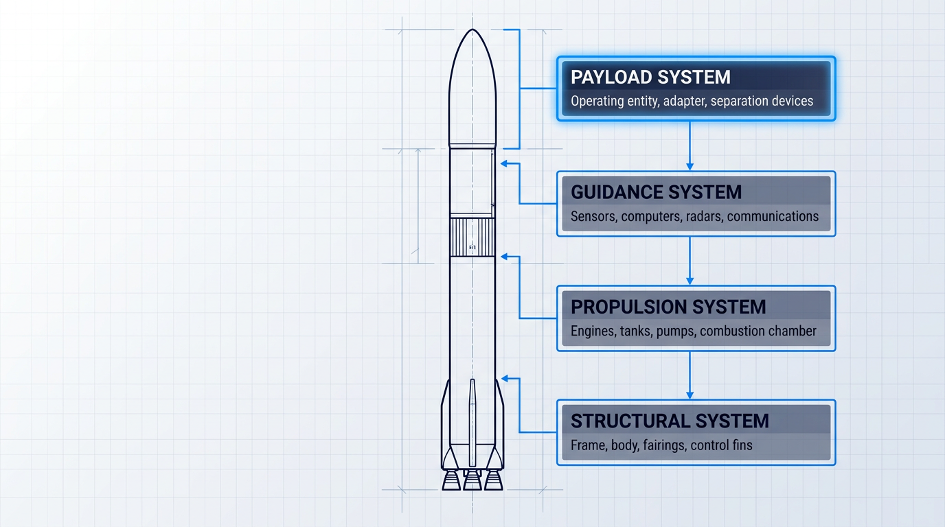
NASA's Glenn Research Center frames any full-scale rocket as having four major systems, each grouped by function. Understanding where the payload system sits within this architecture is the first step to understanding what it is.
- Structural system: The frame of the rocket — the cylindrical body, fairings, and control fins — which transmits flight loads and minimises aerodynamic drag.
- Payload system: The operating entity the rocket is built to carry and deliver, together with its adapter and separation hardware.
- Guidance system: Sensors, on-board computers, radars, and communication equipment that manoeuvre and stabilise the rocket throughout flight.
- Propulsion system: All parts making up the rocket engine — tanks, pumps, propellants, combustion chamber, and nozzle — whose function is to produce thrust.
The payload system is one of these four first-class components, not a sub-element of any other. It sits at the top of the rocket's purpose hierarchy: the other three systems exist to support it.
Payload vs. Launch Vehicle: A Critical Distinction
The launch vehicle — the rocket itself — is the delivery mechanism, not the payload. Once in orbit, the launch vehicle's job is done; it is the payload that remains operational and accomplishes the mission.
A 1971 NASA technical report makes this boundary explicit: the payload is "the total operating entity, such as a satellite, that is launched into orbit by the launch vehicle" — comprising spacecraft and experiments, but excluding launch vehicle elements such as adapters that are non-functional in orbit.
The clearest canonical example is the Hubble Space Telescope. Launched on April 24, 1990 aboard Space Shuttle Discovery on mission STS-31, Hubble was the primary payload: tucked inside Discovery's cargo bay for the journey, then deployed into a 380-statute-mile orbit where it became the operating entity doing the scientific work. Discovery was the launch vehicle; Hubble was the payload.
The Full Payload System: Three Components
When engineers refer to the "payload system" as a rocket component, they mean something broader than the payload object alone. The same 1971 NASA technical report defines the payload system as collectively describing three elements: the payload itself, the payload/launch vehicle adapter (the structural interface connecting spacecraft to rocket), and any separation devices required to effect a clean separation of the payload from the launch vehicle.
This three-part assembly is what must mate cleanly with the launch vehicle during integration — a distinction that becomes important when examining how spacecraft are prepared for flight.
Payload Module and Service Module
Within a spacecraft itself, engineers draw a further distinction between two major sections. The payload module houses the science instruments or mission-specific hardware — the cameras, spectrometers, antennas, or detectors that actually perform the mission. The service module (also called the spacecraft bus) provides the housekeeping functions that keep the payload module alive and operational.
ESA's documentation across multiple missions consistently describes the service module as supplying power generation, attitude and orbit control, thermal management, data handling, and communications — while the payload module carries the instruments those functions exist to support.
The scope of "payload" shifts depending on which system boundary you draw. The payload on a small satellite is the instrument it carries — a neutron detector, a camera, a radio receiver. But the payload on the rocket that launches that satellite is the entire satellite: bus, instruments, and all. As the Pressbooks/EPET302 academic framing puts it, there can exist different levels of payloads if you widen the scope of the system — a fact that becomes especially significant when dealing with CubeSats and rideshare missions.
With the payload system defined — its boundaries, its components, and its place within the rocket's architecture — the natural next question is what it can actually contain. The answer is considerably more varied than most readers expect.
What Payload Systems Carry: A Taxonomy
Ask what a payload system carries and the honest answer is: almost anything a mission requires. The categories that engineers use to classify payloads are not bureaucratic labels — they are direct consequences of mission purpose, and they determine every major design decision that follows, from orbital destination to power budget.
Scientific instrument payloads
Scientific payloads encompass remote sensing instruments, in-situ measurement packages, and astronomical observation instruments — and a single science mission routinely carries all three modalities simultaneously.
ESA's JUICE mission (Jupiter Icy Moons Explorer) illustrates this complexity directly: its payload complement consists of 10 state-of-the-art instruments plus one experiment using the spacecraft's own telecommunication system with ground-based infrastructure.
Those instruments are organised into three distinct packages: a remote sensing package covering imaging and spectral capabilities from ultraviolet to sub-millimetre wavelengths; a geophysical package including a laser altimeter and an ice-penetrating radar; and an in-situ package measuring the particle, magnetic, and plasma environment around Jupiter and its moons.
The JUICE example challenges a common assumption — that a payload is a single instrument pointed at a single target. In reality, a science payload module can house a diverse complement of instruments with different measurement modalities, each with its own pointing, thermal, and power requirements, all sharing a single module structure.
Communication payloads
Some spacecraft exist not to observe the universe but to relay data between other spacecraft and ground stations — their communication payload is not incidental to the mission, it is the mission.
NASA's Tracking and Data Relay Satellite System (TDRSS) is the canonical example of this class: a constellation of spacecraft whose purpose is to provide continuous communication coverage for missions including the Space Shuttle, the International Space Station, and a range of Earth-observing satellites.
The engineering logic here is distinct from science missions — success is measured in communication throughput and coverage continuity, not scientific data return, and the payload design reflects that priority entirely.
Navigation payloads
Navigation payloads carry the signal-generation and transmission equipment that enables positioning and timing services for users on Earth and in orbit — the payload points inward toward Earth's users, not outward toward scientific targets.
The three major Global Navigation Satellite System (GNSS) constellations illustrate the scale of this category: the US GPS constellation operates at least 24 satellites in medium Earth orbit; Russia's GLONASS system provides comparable coverage using L-band navigation signals across 25 channels; and Europe's Galileo system, under civilian control, currently fields 28 satellites offering real-time positioning accuracy down to the metre range.
Each satellite in these constellations carries a payload whose sole function is broadcasting precise timing and ranging signals — the spacecraft bus exists to keep that payload operational, not the other way around.
Earth observation payloads
Earth observation payloads — meteorological and environmental monitoring instruments — impose particularly demanding physical constraints on the payload module that houses them, because instrument performance depends on precise orientation and thermal stability across every orbital pass.
ESA's MetOp satellite demonstrates this clearly: its Payload Module (PLM) has a box-shaped structure with a central cylinder as the main structural load path, housing instrument electronics internally while mounting sensors and antennas on external panels to preserve their fields of view.
The MetOp PLM's thermal control system — combining multi-layer insulation, radiators, and both hardware- and software-controlled heaters — exists specifically to keep each instrument within its predefined operational temperature limits, because a temperature excursion that would be trivial for the bus could compromise a radiometer's calibration entirely.
Human support and cargo payloads
As NASA's own guidance notes, the most important payload a rocket can carry into space is a human being — crewed missions represent the most demanding payload category in terms of life support, abort systems, and crew interface requirements.
Beyond crewed spacecraft, cargo payloads delivered to crewed platforms are governed by formal, itemised manifests — not rough estimates — because mass and volume accounting at the system level is engineering discipline, not logistics.
The Cygnus ORB-2 mission to the International Space Station carried a total of 3,293 pounds (1,493.8 kg) of cargo, broken down across precisely accounted categories: 1,684 lbs of crew supplies, 783 lbs of vehicle hardware, 721 lbs of science investigations, 87 lbs of EVA equipment, and 18 lbs of computer resources.
That level of itemisation reflects a fundamental truth about cargo payload design: every pound on the manifest displaces another, and the manifest is the engineering document that makes those trade-offs explicit before the fairing closes.
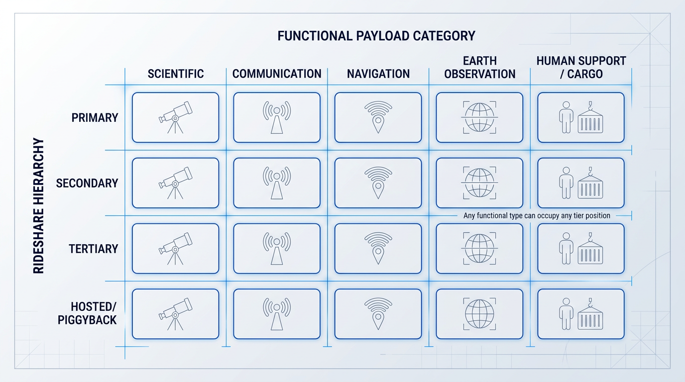
The rideshare hierarchy: primary, secondary, and tertiary
The functional categories above describe what a payload does. A separate, equally important classification describes a payload's relationship to the launch vehicle and other payloads on the same mission — the rideshare hierarchy.
- Primary payload: The spacecraft for which the launch service is procured. It defines orbital parameters — inclination, altitude, insertion accuracy, and launch schedule.
- Secondary payload: Typically a smallsat, deployed after the primary. It is subordinate in orbit selection and cannot delay the launch without the primary's agreement.
- Tertiary payload: Small satellites such as CubeSats and nanosatellites, lower in priority than secondary payloads and deploying last in the sequence.
- Hosted or piggyback payload: Permanently attached to a host spacecraft, sharing its power, thermal management, and communications for the life of the mission.
A secondary payload can be a scientific instrument, a communication relay, or a navigation technology demonstrator — the hierarchy says nothing about function, only about who defines the orbital parameters and who bears the schedule risk.
Primary, secondary, and tertiary designations are determined by who procures the launch and who defines the orbital parameters — not by payload cost, scientific importance, or agency seniority. A CubeSat tertiary payload on a rideshare mission may carry science of equal value to the primary; it simply does not drive the orbit.
Understanding which tier a payload occupies is essential from the earliest mission planning stages, because it determines the degree of influence the payload team has over orbital destination, launch timing, and interface negotiations with the launch provider.
Payload classification is ultimately the first step in a chain of engineering decisions: the type of payload determines its required orbit, which determines the launch vehicle, which constrains the mass budget and fairing volume available, which shapes every interface between the payload and the vehicle.
A scientific instrument requiring a sun-synchronous orbit imposes fundamentally different constraints on the launch vehicle than a communication relay satellite bound for geostationary transfer orbit — and those constraints cascade through every subsequent design choice. The next section examines exactly what those constraints look like in practice.
The Physical Limits That Shape Payload Design
Knowing what a payload system carries is only the beginning. The harder question is what governs how those payloads must be built — because every payload design is simultaneously constrained along multiple axes: mass, volume, power, thermal, mechanical, and radiation.
Satisfying all of those constraints at once, while still accomplishing the mission, is the discipline of payload system engineering.
The mass budget is the foundational constraint from which all others follow. Every launch vehicle has a firm physical ceiling on the payload mass it can deliver to a given orbit — a figure determined by propulsion physics, not negotiation.
Mass properties are tracked formally throughout every design phase: instruments, structure, harnesses, thermal hardware, and margins all draw from the same finite allocation. Every gram added to one subsystem is a gram taken from another — or consumed from the margin that protects the mission if estimates prove optimistic. Mass discipline must be enforced from the earliest concept phase; it cannot be retrofitted once hardware is being built.
Beyond total mass, the distribution of that mass matters just as much. Centre-of-gravity (CG) constraints arise directly from the structural loads the launch vehicle experiences during ascent — particularly bending moments that scale with how far the payload's mass centroid sits from the vehicle's neutral axis. A payload that is within its mass allocation but poorly balanced can impose unacceptable structural loads on the vehicle, making CG compliance as binding as the mass limit itself.
The payload must also fit physically within the payload fairing — the composite nose cone that protects it from aerodynamic and acoustic loads during ascent through the atmosphere. Fairing dimensions set a hard geometric boundary that no amount of mass margin can overcome.
| Launch Vehicle | PLF Diameter | PLF Length (Standard) | PLF Length (Long) |
|---|---|---|---|
| Falcon 9 (SpaceX) | 5.2 m (17.1 ft) | 13.1 m (43 ft) | — |
| Vulcan Centaur (ULA) | 5.4 m (17.7 ft) | 15.5 m (51 ft) | 21.3 m (70 ft) |
Direct comparison of confirmed fairing dimensions from first-party sources for two major launch vehicles, illustrating the concrete geometric constraints payload designers work within.
These dimensions define the outer boundary, but the usable volume is more constrained than the headline figures suggest. The fairing envelope tapers toward the nose, which means the available cross-section shrinks as instruments are positioned higher within the stack — a three-dimensional geometry problem, not simply a diameter check.
With the geometric and mass constraints established, the remaining challenges concern the environments the payload must survive — from the moment of liftoff through to its operational life in orbit. The eight principal constraint categories that payload engineers work within are:
- Mass budget: A firm ceiling on total payload mass set by launch vehicle performance to the target orbit; tracked via formal weight budgets with margin discipline.
- Centre of gravity: The payload's mass distribution must keep the CG within specified bounds to avoid unacceptable bending loads on the vehicle during ascent.
- Volume envelope: The three-dimensional fairing interior is the absolute geometric limit; usable volume tapers toward the nose, constraining instrument placement.
- Thermal environment: Payloads cycle between solar illumination and deep shadow in orbit; heat transfer is by radiation only, requiring careful thermal design and TVAC qualification.
- Vibration and acoustic loads: Launch generates quasi-static, sine, random vibration, and intense acoustic environments that hardware must survive and continue functioning through.
- Shock environment: Separation events produce sharp, high-frequency shock loads that can damage sensitive optical or electronic components if not designed for.
- Radiation environment: Ionising radiation from the Van Allen belts, cosmic rays, and solar particle events degrades electronics; component selection requires a formal hardness trade-off.
- Power budget: Available power from the spacecraft bus is a finite, allocated resource; competing subsystems may not all operate simultaneously at full draw.
The thermal challenge is particularly demanding because the space environment offers no middle ground. A payload in low Earth orbit cycles between direct solar illumination and complete shadow with each orbit, and without an atmosphere to carry heat by convection, the only mechanism available for thermal management is radiation and conduction through structure.
Instruments must remain within a defined operating temperature range throughout that cycling, which requires active thermal design — heaters, radiators, multi-layer insulation — rather than passive tolerance. Qualification requires thermal-vacuum (TVAC) testing: NASA's GSFC-STD-7000A standard specifies that payloads must complete a minimum of four thermal-vacuum temperature cycles at the payload level of assembly, with a minimum 24-hour dwell at each temperature extreme per cycle, and at least 100 trouble-free hours of functional operation at both hot and cold conditions.
For hosted payloads — instruments flying on a host spacecraft — the thermal interface adds another layer of constraint. The NASA Hosted Payload Interface Guide specifies that conductive heat transfer at the instrument-to-spacecraft mechanical interface should not exceed 15 W/m² or 4 W, whichever is greater, ensuring the payload manages its own thermal needs without burdening the host.
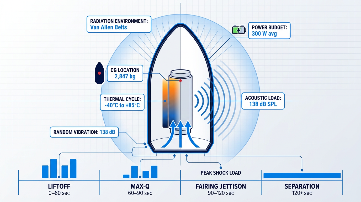
The mechanical load environment during launch is structured and well-characterised, but no less demanding for that. GSFC-STD-7000A identifies the key environments payload hardware must be designed and tested against: quasi-static loads (sustained acceleration during powered flight), sine vibration (low-frequency structural resonance, tested at 1.25 times the flight limit level for qualification), random vibration (broadband, tested at limit level plus 3 dB for qualification, for a minimum of one minute per axis), and acoustic environments — with a minimum qualification acoustic test level of 138 dB.
Shock is a distinct environment from vibration and demands its own treatment. When a payload separates from the launch vehicle, the release mechanism generates a sharp, high-frequency transient that propagates through the payload structure in milliseconds. Separation shock can fracture optical alignments, crack solder joints, or latch electronic relays into unintended states — damage that may not manifest until the payload is in orbit and unreachable.
The radiation environment presents a different kind of engineering challenge because it is invisible, cumulative, and orbit-dependent. Ionising radiation from trapped protons and electrons in the Van Allen belts, galactic cosmic rays, and solar particle events affects all electronic components — through total ionising dose (TID), displacement damage, and single event effects (SEE) that can corrupt data, reset systems, or cause permanent device failure.
This drives one of payload engineering's most consequential component-selection trade-offs: radiation-hardened parts versus commercial off-the-shelf (COTS) components. Radiation-hardened devices are designed and manufactured with controlled processes to tolerate the space environment, but they typically lag commercial technology by one or more generations and carry significantly higher procurement costs and lead times. COTS parts offer higher performance and lower cost, but their radiation tolerance is often unknown or insufficient for the mission dose, and lot-to-lot variation in radiation sensitivity can be substantial.
NASA guidance frames this as a genuine engineering trade, not a simple preference: the right answer depends on the mission orbit, duration, and criticality of each component. A short-duration LEO mission may accumulate only 5–10 krad(Si) of total ionising dose — a level many modern COTS parts can tolerate — while a multi-year GEO mission or a trajectory through the Van Allen belts demands a far more rigorous hardness assurance programme, including ground radiation testing and defined radiation design margins.
Power is the final resource constraint, and it operates differently from the others because it is dynamic rather than fixed. The power budget allocates available electrical power from the spacecraft bus among all subsystems, and for hosted payloads the allocation is formally specified in the interface documents. The NASA Hosted Payload Interface Guide notes that a hosted instrument drawing up to 300 W of orbital average power represents the level that the primary spacecraft bus manufacturers can accommodate — above that, hosting opportunities narrow considerably.
When power is scarce, instruments cannot all run simultaneously at full capacity, forcing operational trade-offs that must be anticipated in the mission design long before launch. The electrical power system typically accounts for a significant fraction of spacecraft volume and mass — meaning the power constraint feeds back directly into the mass and volume constraints it sits alongside.
Excellent payload engineering is not about working around mass, volume, thermal, radiation, and power limits — it is about designing within all of them simultaneously, without compromising mission capability. A payload that satisfies every constraint elegantly while still accomplishing its scientific or operational purpose represents the highest expression of the discipline.
Understanding these constraints is the foundation — but knowing them in isolation is not enough. Once a payload has been designed to satisfy its mass budget, fit within the fairing envelope, survive the load environments, and operate within its thermal and power limits, it must be physically brought together with the launch vehicle. That integration process has its own rigour, its own documentation, and its own critical path — which is where the next part of this guide picks up.
Payload Integration: Mating the Payload to the Rocket
After years of design work, analysis, and component-level testing, there comes a moment when the spacecraft leaves its cleanroom and meets its launch vehicle for the first time. That moment is the beginning of payload integration — and everything that follows is irreversible.
Payload integration is more than mechanical attachment. It is the first-time assembly of all payload hardware into launch configuration, verifying mechanical fit, electrical systems operation, and full systems compatibility in a way that component-level testing simply cannot replicate.
The Payload Attach Fitting
The structural bridge between the spacecraft and the rocket's upper stage is the payload attach fitting (PAF) — a precision-engineered interface that is far more than a simple bracket.
The PAF is a sandwich composite structure designed to transfer dynamic loads — vibration, shock, and quasi-static acceleration — between the spacecraft and the launch vehicle without distorting either. Launch vehicles typically offer a range of PAF configurations to accommodate different spacecraft interface diameters and mass properties, with each configuration's structural properties formally documented in the vehicle's user guide.
The PAF also defines the mechanical interface plane: the ring at which the spacecraft's separation system engages, and the datum from which all structural load calculations are referenced. Getting the PAF selection and verification right is a prerequisite for everything else in the integration sequence.
Fairing Encapsulation
With the spacecraft mated to the adapter at a payload processing facility, the next step is fairing encapsulation: the fairing halves are closed around the payload, sealing it into flight configuration.
Encapsulation is a critical milestone in the integration timeline. Once the fairing is closed, the payload is no longer fully accessible for hands-on work — any last-minute anomaly that requires physical access becomes a major schedule and safety event.
The fairing's job during this period is to protect the payload from aerodynamic pressure, acoustic energy, thermal gradients, and electromagnetic environments — both during ground transport to the launch pad and during ascent through the atmosphere.
Once the vehicle climbs above the sensible atmosphere, the fairing is no longer needed and is jettisoned. At that point, the payload is exposed to the space environment for the first time — a transition that typically occurs within the first few minutes of flight, at an altitude and timing that varies by vehicle and trajectory.
Interface Control Documents
Running beneath every physical step of integration is a documentation discipline that makes multi-party integration tractable: the Interface Control Document (ICD).
An ICD is a formal agreement that defines every interface between the payload and the launch vehicle or host spacecraft — covering mechanical attach points, electrical connectors, data protocols, and thermal contact surfaces. It specifies what each side of the interface must look like, who is responsible for verifying compliance, and what formal change process must be followed if anything needs to be modified.
Before an ICD is signed, interface ambiguity is an engineering risk. After it is signed, each party — payload developer and launch integrator — knows exactly what they own, what they must verify, and what they cannot change unilaterally. That clarity is what makes multi-party integration possible.
ICD change control is deliberately rigorous. A unilateral design change that crosses an interface boundary — even a seemingly minor one — can invalidate the other party's structural analysis, thermal model, or electrical verification, with cascading effects that reach all the way to the launch date.
This is why ICDs are treated as living controlled documents rather than one-time deliverables. Every revision must go through a formal review and approval cycle involving both parties, ensuring that interface assumptions remain synchronised throughout the integration campaign.
Verification and Acceptance Testing
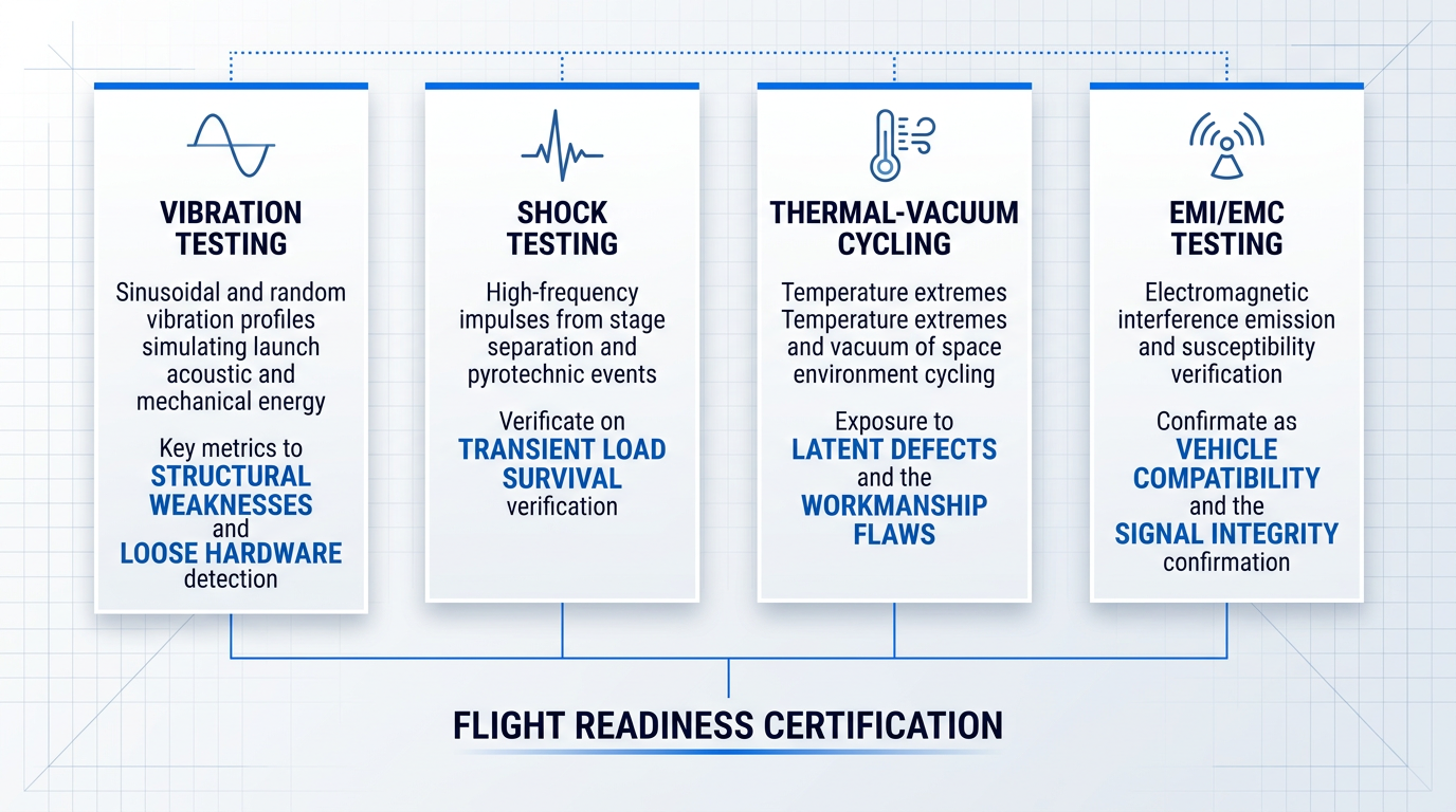
Before a payload can be handed over to the launch integrator, it must be certified as flight-ready through a structured testing campaign that proves it can survive the launch environment.
- Vibration Testing: Subjects the payload to sinusoidal and random vibration profiles simulating launch acoustic and mechanical energy, catching structural weaknesses and loose hardware before flight.
- Shock Testing: Replicates high-frequency impulses from stage separation and pyrotechnic events, verifying that components and joints survive sudden high-amplitude transient loads.
- Thermal-Vacuum (TVAC) Cycling: Cycles the payload through the temperature extremes and vacuum of the space environment, exposing latent material or workmanship defects that ambient testing cannot reveal.
- EMI/EMC Testing: Verifies the payload neither emits interference affecting the launch vehicle nor is susceptible to electromagnetic energy from the vehicle's own systems.
Taken together, these tests constitute a proof of survivability, not just a checklist. A payload that passes all four campaigns has been demonstrated — not merely predicted — to survive from pad to orbit.
The Integration Lifecycle: Milestone Reviews
The path from initial design to launch clearance is governed by a sequence of formal milestone reviews. Each one is a gate, not a formality: the payload cannot advance to the next phase without demonstrating documented compliance with its requirements at that stage.
- Preliminary Design Review (PDR): Confirms the design approach is sound and requirements are allocated and traceable before detailed design work begins.
- Critical Design Review (CDR): Verifies the detailed design is complete, drawings are releasable, and analyses confirm the design meets all interface and performance requirements.
- Pre-Ship Review: Confirms the as-built payload matches the design baseline, all acceptance testing is complete, and hardware is ready for transport to the launch site.
- Certification of Flight Readiness (CoFR): The final gate: all parties certify that the integrated vehicle is ready to fly, with no open safety or compliance issues.
Each review demands a defined set of deliverables — drawings, analyses, test reports, and interface verifications — that the payload team must produce and defend. A payload that cannot demonstrate compliance at CDR does not proceed to integration; the gate holds until the evidence is there.
This milestone structure is not arbitrary. It mirrors the natural maturity progression of a hardware programme, ensuring that problems are caught at the stage where they are cheapest to fix — in analysis at PDR, in design at CDR, and in hardware at Pre-Ship — rather than at the launch pad.
Separation: The Culmination of Integration
Every step of the integration process — the PAF selection, the ICD negotiations, the testing campaigns, the milestone reviews — exists in service of a single event: the separation event.
Separation must be clean, controlled, and precisely timed. The spacecraft must depart the launch vehicle at the right moment, in the correct orientation, with the velocity vector needed to reach its target orbit or trajectory. Any deviation — a stuck separation device, an incorrect attitude, a timing error — can compromise or end the mission.
Critically, the separation devices — whether pyrotechnic cutters, spring-loaded push-off mechanisms, or motorised release systems — are part of the payload system definition, not the launch vehicle's. The payload developer owns and verifies the separation system; the launch provider's responsibility ends at the interface plane.
When separation is confirmed and the spacecraft is flying free, the integration process is complete. The mission has begun — and every engineering decision made over the preceding years either holds or it doesn't.
The integration lifecycle described here never unfolds in isolation. It involves payload developers, launch integrators, range safety authorities, and agency oversight teams working in parallel across the same timeline — and managing those organisational interfaces is as demanding as managing the physical ones. That collaboration challenge is what the next section explores.
How Agencies and Industry Collaborate on Payload Development
Ask who builds a space mission and the answer is rarely one organisation. A typical payload development effort spans a government agency that defines the science objectives, one or more prime contractors that build the hardware, subcontractors that supply components, and a launch provider that integrates and flies the vehicle — each operating on different timelines, answering to different stakeholders, and owning different pieces of the system.
The fundamental shift that shapes modern payload collaboration is the move away from cost-plus contracting, where the agency defined both what the mission would accomplish and precisely how the hardware would be built. Under that model, cost overruns were largely the government's problem. The commercial-era alternative transfers implementation authority to industry: the agency defines the requirement, and the company decides how to meet it — with any cost overrun becoming the company's financial responsibility, not the government's.
NASA's Commercial Orbital Transportation Services (COTS) programme, launched in 2006, is the canonical demonstration of this shift. Rather than procuring spacecraft hardware, NASA invested in commercial partners through performance-based, fixed-price milestones — funding was issued only after predefined objectives were met. SpaceX and Orbital Sciences Corporation (now Northrop Grumman) each contributed more than 50 percent of their own development costs, fundamentally changing who bore the financial risk.
The follow-on Commercial Resupply Services (CRS) contracts then purchased delivery services rather than vehicles: SpaceX's Dragon spacecraft and Northrop Grumman's Cygnus spacecraft have since delivered cargo to the International Space Station under firm-fixed-price contracts, with NASA defining the destination and cargo manifest while industry owns the vehicle design and operations.
ESA's Partnership Projects Model
ESA operates a parallel but structurally distinct model through its ARTES Partnership Projects (Advanced Research in Telecommunications Systems). Where NASA's commercial model shifts financial and development risk to industry, ESA's approach involves a deliberate split: ESA bears the risks associated with developing innovative technical solutions, while the commercial operator assumes the commercial and market risks.
Three programmes illustrate this model in practice. Eutelsat Quantum, developed under a public-private partnership between ESA, Eutelsat, and Airbus, became the first fully software-defined commercial satellite capable of being completely reprogrammed in orbit. EDRS (European Data Relay System), a partnership between ESA and Airbus, built the SpaceDataHighway using laser communication technology to relay data from low-orbit satellites to geostationary orbit. Space INSPIRE (INstant SPace In-orbit REconfiguration), developed with Thales Alenia Space under the Novacom II ARTES programme, extends the same reconfigurability approach to a new product line of geostationary satellites.
ESA's own description of the model is direct: without the partnership approach, many of these projects would not have emerged because they would have been too risky either technically or commercially for either party to pursue alone.
Across both the NASA and ESA models, the collaboration requires a formal accountability instrument to make it work. The Payload Integration Agreement (PIA) is that instrument. For NASA's Space Launch System, the PIA establishes and implements all management and programmatic integration requirements between the spacecraft or payload and the launch vehicle — defining roles and responsibilities, interfaces, standard and non-standard services, deliverable exchanges, and the overall schedule. It is the document that makes the collaboration legible and enforceable across organisational boundaries.
The PIA is developed early and baselined when the payload is formally manifested, but it is not static — revisions are negotiated and agreed to by all parties as the programme evolves. In practice, the PIA works in tandem with the payload-specific Interface Control Document (ICD), which defines the precise hardware and software interfaces between the payload and the launch vehicle or host platform.
As established in the integration section of this guide, ICDs are the technical accountability boundary between parties. In a multi-organisational collaboration, they serve an additional function: when agency and industry timelines diverge — which is common — ICD milestones become the concrete mechanism for managing that divergence. A missed ICD milestone is a documentable event with schedule consequences, not an informal disagreement. That specificity is what makes the ICD useful as a coordination tool, not just a technical specification.
Beyond the dedicated mission model, agencies and industry have developed additional collaboration structures that allocate risk and responsibility in meaningfully different ways.
- Dedicated mission: Agency or industry owns the full spacecraft; payload is the primary mission. Maximum control, maximum cost.
- Hosted payload: A government payload rides permanently on a commercial host spacecraft, sharing its power, thermal, and data resources.
- Commercial Lunar Payload Services: Companies own and develop the lander; NASA defines the payload manifest and science objectives under firm-fixed-price contracts.
The hosted payload model is the most operationally distinctive of these structures. A hosted payload is permanently attached to a host spacecraft and depends on it for resources including power, thermal management, volume, and communications — but its mission objective is independent of the host's primary mission. NASA's Laser Communications Relay Demonstration (LCRD) illustrates this clearly: the LCRD payload was developed by NASA's Goddard Space Flight Center and integrated onto the U.S. Department of Defense's Space Test Program Satellite 6 (STPSat-6), with Northrop Grumman performing the physical integration.
The trade-off is structural: the hosted payload typically does not drive the host's launch schedule or orbital placement, and it pays for its own integration and the marginal costs of the resources it consumes. The dependency on the host's operational decisions is real — but the cost reduction compared to a dedicated spacecraft and launch can be substantial.
NASA's Commercial Lunar Payload Services (CLPS) initiative represents the furthest extension of the commercial model to date. Established in 2018, CLPS selected a pool of commercial vendors to compete on firm-fixed-price task orders for end-to-end payload delivery to the lunar surface — from payload handover through delivery and operation. The contractor, not NASA, is responsible for the full scope of delivery, and NASA deliberately limited its oversight of contractor designs, systems, processes, and infrastructure.
The NASA Office of Inspector General's 2024 audit of CLPS (IG-24-013) found that the initiative has faced significant challenges: five of eight task orders experienced both schedule delays and cost increases, with an average delay of 14 months per task order and total cost increases of $208.2 million across the initiative. The OIG also found that the use of firm-fixed-price contracts shifted production and cost risks to CLPS vendors, creating financial pressures for smaller companies — contributing to one vendor's bankruptcy.
CLPS demonstrates that moving financial and development risk from agency to industry does not make the risk disappear — it changes who absorbs the consequences when missions slip or fail. One CLPS vendor went bankrupt; NASA lost $66 million and one flight opportunity as a result. The accountability structure determines who bears the cost, not whether the cost exists.
Across all of these models, the engineering reality of collaboration involves layers of complexity that well-managed teams treat as a capability rather than a burden. Safety review processes for payloads operating in crewed environments run across multiple phases, with each phase potentially taking up to two months — and that is before accounting for verification testing. Interface incompatibilities between agency and industry hardware are a routine challenge, not an edge case. The teams that master the PIA, ICD, and safety review cadence move faster and with fewer integration surprises than those that treat the documentation as an afterthought.
At the scale of CubeSats and nanosatellites, the collaboration model simplifies considerably — rideshare arrangements, standardised interfaces, and shorter timelines compress much of this structure. But the underlying discipline of managing interfaces across organisational boundaries remains, regardless of spacecraft size.
CubeSats: Payload Engineering at Miniature Scale
Compress every engineering constraint covered in earlier sections — mass, volume, power, data rate — into a box the size of a loaf of bread, and you begin to understand what CubeSat payload engineering actually demands. This is not simply conventional spacecraft design scaled down; it is a qualitatively different discipline, where the margin for error collapses to near zero and every subsystem trade-off directly determines whether a payload can fly at all.
The CubeSat standard defines a base unit, the 1U, as a 10×10×10 cm cube. The CubeSat Design Specification (CDS Rev. 14.1) sets the maximum mass for a 1U at 2.00 kg, a 3U configuration — measuring 10×10×34 cm — at 6.00 kg, and a 12U at 24.00 kg. The older per-unit figure of 1.33 kg, which appears in earlier CDS revisions and the USU SmallSat literature, remains widely cited as the original standard.
| Form Factor | Dimensions (cm) | Max Mass — CDS Rev. 14.1 (kg) |
|---|---|---|
| 1U | 10 × 10 × 10 | 2.00 |
| 3U | 10 × 10 × 34 | 6.00 |
| 6U | 20 × 10 × 34 | 12.00 |
| 12U | 20 × 20 × 34 | 24.00 |
CubeSat form factor comparison by dimensions and maximum mass per CDS Rev. 14.1, anchoring the constraint discussion with authoritative figures.
ESA notes that a 3U is typically the minimum form factor that can meaningfully accommodate a small technology payload — the 1U leaves so little volume once bus systems claim their share that science or technology demonstration instruments are extremely difficult to fit.
The payload mass fraction on real 1U missions varies considerably: real-mission data from the Hermes and Artemis CubeSat programmes shows payload allocations as low as 2% of dry mass, while the SMAD textbook suggests 41% as a notional target. In practice, bus systems dominate the budget — power generation, attitude control, communications hardware, and structure each compete for the same scarce grams and cubic centimetres, leaving payload designers to work within whatever margin remains.
Power is where the constraint becomes most operationally consequential. Orbit-average power for a small CubeSat in sun-synchronous orbit sits on the order of 1–2 W — a figure confirmed by NASA technical literature on CubeSat power subsystems. At that level, attitude control hardware and payload instruments typically cannot run simultaneously, forcing mission designers to sequence subsystem operation carefully across orbital windows rather than simply allocating less power to each.
This sequencing requirement is a unique operational discipline. It is not merely a matter of having less power available; it demands a fundamentally different approach to mission scheduling, where the spacecraft cycles between control modes and science modes in carefully timed intervals, sometimes across multiple orbits before a single observation window is possible.
The data rate constraint is equally consequential for payload selection. Standard CubeSat platforms operate within a downlink envelope of approximately 1 Mbps — a ceiling set by the antenna aperture, transmit power, and link geometry achievable within the form factor. Some CubeSats have exceeded this with specialised hardware, but it represents the practical limit for standard platforms.
That ceiling functionally excludes entire classes of Earth observation payload technology. As MIT System Architecture research confirms, the following instrument types are simply incompatible with standard CubeSat link budgets:
- Synthetic aperture radar (SAR): Generates large data volumes requiring high-bandwidth downlinks far exceeding standard CubeSat RF capabilities.
- Lidar: Data volumes and pointing precision requirements are incompatible with CubeSat mass, power, and link budgets.
- High-resolution optical imagers: Full-resolution imagery produces data rates that overwhelm the ~1 Mbps downlink envelope of standard platforms.
- Hyperspectral instruments: Spectral data cubes are data-intensive; throughput requirements cannot be met within standard CubeSat communications constraints.
The practical result is that CubeSat payloads gravitate toward simpler sensors, in-situ measurement instruments, and technology demonstrators — not because engineers lack ambition, but because those are the payload classes the physics genuinely permits at this scale.
The same constraints that restrict individual capability become strategic assets at the fleet level. Because CubeSats are small and standardised, they qualify as secondary or tertiary payloads on rideshare missions, reaching orbit at a fraction of the cost of a dedicated launch. A constellation of ten 3U CubeSats measuring atmospheric chemistry simultaneously at multiple orbital nodes can deliver science that a single large spacecraft — limited to one observation point at a time — simply cannot replicate.
A constellation of small CubeSats making simultaneous multi-point observations can produce science results that no single large spacecraft is geometrically capable of delivering — turning the CubeSat's individual limitations into a collective scientific advantage.
The choice to use commercial off-the-shelf (COTS) components rather than fully space-qualified parts is a deliberate engineering judgement calibrated to the mission environment. In LEO, the radiation environment is comparatively benign, mission durations are typically one to three years, and the acceptable risk tolerance is higher than for flagship missions — conditions that make a careful COTS approach technically defensible while compressing cost and development time significantly.
ESA's CubeSat programme frames this combination of standardisation, modularity, and COTS subsystem availability as a structural advantage: CubeSat projects can be ready for flight in one to three years, compared to the five-to-ten-plus year timescales typical of large flagship missions. ESA explicitly positions CubeSats as drivers of miniaturisation technology, enablers of distributed in-situ measurements, and platforms for technology demonstration.
The deeper lesson from CubeSat payload engineering is transferable. Designing within a 1U or 3U envelope — minimising mass ruthlessly, sequencing power-hungry subsystems, selecting COTS components with calibrated risk tolerance — builds an intuition for constraint-driven design that applies at any spacecraft scale. Engineers who have worked in this environment tend to approach larger missions with a sharper eye for margin and a lower tolerance for unnecessary complexity.
The data rate limitations that define what CubeSat payloads can and cannot do are, in a broader sense, symptomatic of a challenge facing the entire satellite communications sector: RF bandwidth is a finite and increasingly contested resource, and the industry response to that pressure is reshaping how communication payloads are designed across all spacecraft classes — which is the subject of the next section.
Communication Payloads and the Shift Toward Optical Links
A spacecraft's science instruments determine what it can observe — but its communication payload determines what it can actually say, and to whom. That distinction matters enormously: a mission that cannot return its data at a useful rate has, in practical terms, failed to complete its purpose.
Communication payloads are spacecraft systems whose primary function is relaying data between ground stations, other spacecraft, and end users — telemetry, science data, command uplinks, and relay services. Unlike scientific instruments, a communication payload is not measuring the universe; it is the pipeline through which everything measured gets home.
The RF Spectrum: A Finite and Contested Resource
The RF spectrum is not a free good. Every frequency band used by spacecraft is allocated, licensed, and coordinated internationally — and the agencies doing that coordination are running out of headroom.
ESA's Space Frequency Coordination Group (SFCG) brings together 29 member agencies, including NASA and ESA, specifically to manage civil spaceflight frequency use across an increasingly congested electromagnetic landscape.
The congestion picture is concrete and band-specific. X-band deep-space downlink frequencies (8,400–8,450 MHz) are already crowded with Mars missions competing for the same narrow allocation; S-band faces pressure from commercial wireless broadband sharing adjacent spectrum; and the industry's current response is migration toward Ka-band, where wider allocations support higher data rates.
That migration is not a free upgrade. Moving up the frequency ladder improves gain-to-aperture ratios and opens wider spectrum, but it introduces greater atmospheric attenuation and susceptibility to rain fade — and Ka-band is itself approaching practical limits as more missions adopt it.
Free-Space Optical Communications: Beyond the RF Ceiling
Free-space optical (FSO) communications is the structural engineering response to RF spectrum exhaustion — not a novelty, and not a research curiosity. Optical links operate at wavelengths that sidestep licensed radio spectrum entirely and can carry data volumes that no RF system can match within any realistic power and aperture budget.
The operational demonstrations now validate the technology at scale. NASA's TBIRD experiment demonstrated 200 Gbps optical downlink from low Earth orbit, and the Laser Communications Relay Demonstration (LCRD) demonstrated 1.244 Gbps optical relay.
ESA, tracking NASA's DSOC experiment aboard the Psyche spacecraft, established Europe's first deep-space optical communication link at a distance of 265 million kilometres — a link that no RF system could have sustained at comparable data rates across that range.
What FSO demands from payload and ground infrastructure design is qualitatively different from RF. Optical terminals require precise pointing, acquisition, and tracking (PAT) — the divergence of a laser beam is so narrow that pointing errors tolerable in an RF system would break the link entirely.
When a mission selects optical over RF, the spacecraft payload decision and the ground station investment become inseparable — the uplink amplifier, beam management architecture, and PAT system must all be specified together, not sequentially. Treating them as separate procurement decisions is where optical ground station programmes run into trouble.
On the spacecraft side, the shift toward optical also changes the risk calculus around communication standards. Fixed-function payloads locked to a single protocol represent a design liability when standards are still evolving.
Software-defined payloads — exemplified by ESA's Eutelsat Quantum satellite and the Space INSPIRE product line — allow in-orbit reallocation of frequency bands, power, and coverage areas without new hardware. This is established practice, not a future aspiration, and it reflects a broader principle: configurability is risk mitigation.
ESA's own definition of Payload Systems explicitly covers ground equipment and the telecommunication systems through which spacecraft payloads are controlled — the ground segment is integral to the payload system, not an operational afterthought bolted on after the spacecraft is built.
That integration becomes especially consequential in optical ground station uplink design, where the amplifier must simultaneously handle the tracking beacon and data transmission in a coherent, managed beam.
Our own erbium-doped fibre amplifier (EDFA) illustrates what end-to-end configurability looks like in this context: the tracking beacon and uplink data are nested within a single amplified beam, with the beacon tone riding low in amplitude and the data modulated above it — a single-beam architecture that keeps PAT and data functions coherent without requiring separate optical paths.
The system is configurable across both hardware and software. Hardware selection covers C-band, L-band, or dual-band from a single source, with output power at 10 W standard and higher outputs available on request. WSL's Modulation-on-Demand software layer allows waveform, frequency, modulation index, and combined beacon-plus-data modulation to be set in software, with switchable compliance to CCSDS or SDA standards at high power.
Because WSL designs, builds, qualifies, and supports the amplifier entirely in-house on patented technology — with engineering expertise rooted in Southampton's Optoelectronics Research Centre, the birthplace of the EDFA — the configurability extends across both the physical build and the control layer in a way that resellers or catalogue importers cannot replicate. CE and UKCA certification is standard.
The software-defined and optical threads running through this section are part of a broader transformation in how the industry thinks about payload capability over a mission's lifetime — one that extends further into automation, onboard intelligence, and on-orbit servicing, which the next section examines.
Software-Defined Payloads, Autonomy, and On-Orbit Servicing
Most payload systems launched in the last decade were fixed-function by design: once in orbit, their operating parameters were locked, and any mismatch between the payload's capabilities and evolving mission demands was simply a cost the operator absorbed. The next generation is being engineered from the outset to be updated, extended, and in some cases physically serviced after launch — a structural shift in payload engineering philosophy driven not by ambition but by documented constraints.
Software-Defined Payloads: Reconfigurability as Risk Management
Locking a payload to today's frequency allocations, waveform standards, or coverage geometry is a design risk when those standards are still actively evolving — a point that applies as much to Ka-band LEO constellations as to GEO broadcast satellites.
Eutelsat Quantum and the Space INSPIRE product line — both covered in the previous section — established that full in-orbit reconfiguration of frequency bands, power distribution, and coverage areas is operationally viable, not theoretical. Space INSPIRE's first satellite, ASTRA 1Q, is scheduled for launch in 2026 with a fully software-defined payload architecture that allows operators to dynamically reallocate frequency, power, and coverage throughout the satellite's operational lifespan.
The active hardware development programme that extends this capability to small LEO satellites is ESA's KASOM project: a Ka-band flexible and reconfigurable system-on-module (SoM) built around a highly integrated hardware and software programmable RF system-on-chip.
KASOM demonstrates configurability across frequency allocation, channel bandwidth, data rate, waveform, switching, multiplexing, and beamforming — and it does so with a scaled engineering model representative of a Ka-band SoM payload for a small LEO satellite in form, fit, and critical functions. The project targets Technology Readiness Level 5, meaning the technology is validated in a relevant environment, not just on paper.
Onboard Intelligence and Autonomy
Software-defined payloads address the reconfigurability problem; onboard intelligence addresses a different constraint — the impracticality of relying on continuous ground operator input as missions push further from Earth.
NASA's small spacecraft avionics state-of-the-art assessments document the convergence of FPGA-based software-defined radios, AI/ML accelerators, and edge computing as the enabling hardware layer for autonomous decision-making onboard spacecraft. SDRs built on FPGAs can transmit and receive across widely different radio protocols using a modifiable, reconfigurable architecture; AI/ML processors and subsystem-integrated edge computing handle real-time pattern recognition and autonomous response without waiting for ground commands.
The constraint forcing this shift is concrete: at maximum separation from Earth, the Deep Space Network is already oversubscribed, and current RF systems at Mars deliver only a few hundred kilobits per second — making ground-loop-dependent operations impractical for time-sensitive onboard decisions.
The Deep-Space RF Aperture Problem
The Mars data rate ceiling is not simply a function of distance — it reflects a hard physical trade-off between link performance and spacecraft mass budgets that NASA has calculated explicitly.
Transmitting 100 Mb/s from Mars to Earth via RF at maximum range would require a 500 W Ka-band transmitter paired with a ~5.6 m transmit antenna on the spacecraft — mass and volume constraints that are impractical for most mission architectures, even when multiple ground assets in the DSN are arrayed to receive.
This calculation, drawn from NASA's strategic deep-space communications planning, is the engineering argument for optical trunk lines between Mars and Earth — not a speculative preference for a newer technology, but a documented consequence of what RF physics requires at interplanetary distances.
NASA's Space Technology Mission Directorate envisions near-term deep-space communication architectures that combine Ka-band RF for proximity links with optical trunk lines for Earth–Mars data transfer. Payload designers working on Mars-capable systems must accommodate both link types, with software-defined flexibility to transition between standards as the optical relay infrastructure matures.
A 100 Mb/s RF return link from Mars requires 500 W of transmit power and a ~5.6 m antenna — hardware that exceeds the mass and volume budget of most spacecraft. That single engineering constraint, documented in NASA's deep-space communications roadmap, is the primary driver for optical trunk lines becoming part of the Mars communication architecture.
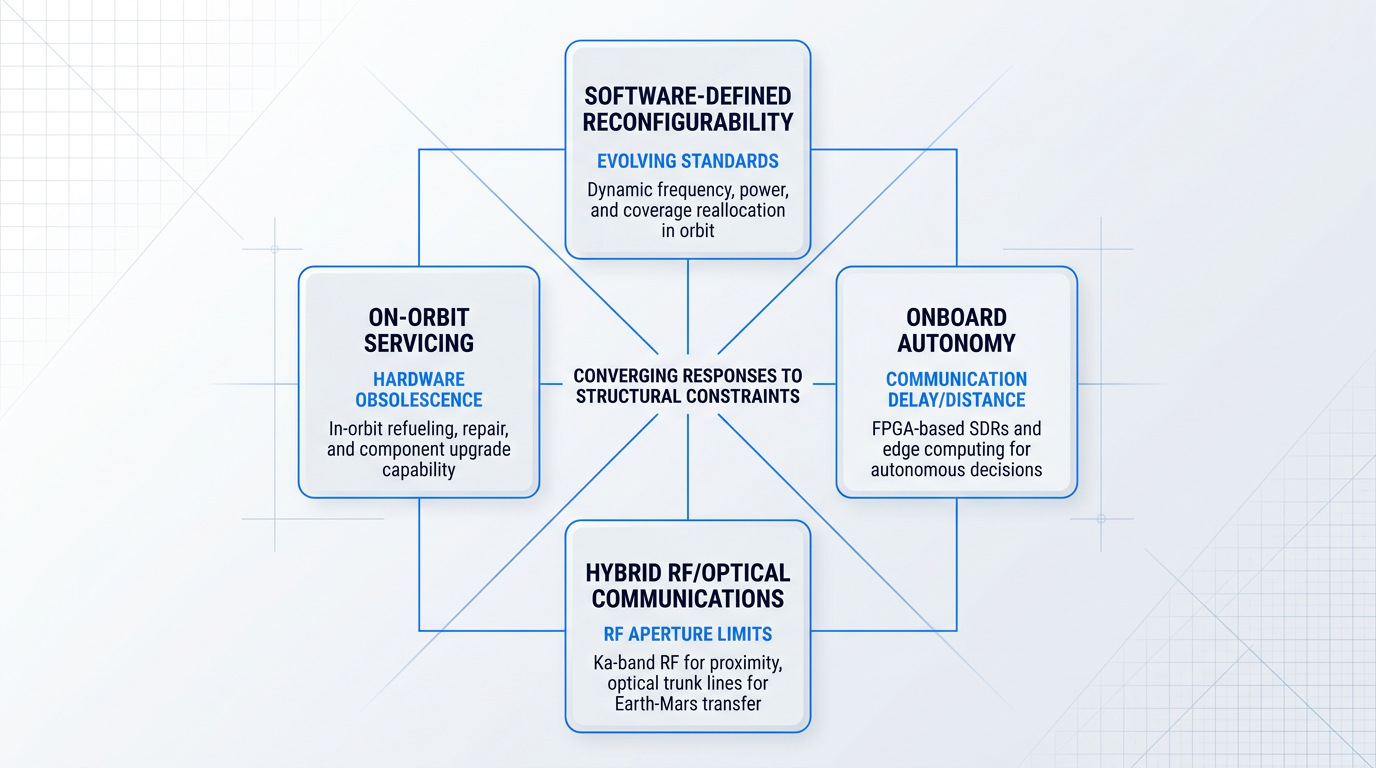
The convergence of software-defined flexibility, onboard autonomy, and hybrid RF/optical link capability represents three of the four major axes along which payload system engineering is advancing. The fourth addresses a different dimension: what happens to payload hardware after it reaches orbit.
On-Orbit Servicing and the Design Calculus Shift
NASA's In-Space Servicing, Assembly, and Manufacturing (ISAM) initiative is the programmatic home for technologies that refuel, repair, or upgrade satellites after launch, and extend the capability to assemble large in-space structures that cannot be launched in a single vehicle.
Among ISAM's active flight projects is the SSPICY mission (Small Spacecraft Propulsion and Inspection Capability), designed to mature the technologies needed for U.S. commercial satellite servicing and logistics — including inspection of defunct satellites as a precursor to repair or deorbit operations.
The engineering significance for payload design is a shift in the fundamental design trade-off: if hardware can be upgraded or replaced in orbit, the case for designing every subsystem to survive the full mission lifetime at maximum performance weakens. Payload designers can instead optimise for near-term capability, knowing that servicing infrastructure may extend operational life or refresh obsolete components.
Taken together, these four directions — software-defined reconfigurability, onboard autonomy, hybrid RF/optical link architectures, and design-for-serviceability — are not parallel trends that happen to be active simultaneously. They are converging responses to the same underlying pressures: spectrum congestion, increasing distance from Earth, mass and volume constraints, and the pace at which standards evolve faster than fixed-function hardware can adapt.
Building payload systems that are lighter, smarter, more reconfigurable, and capable of operating further from Earth with less ground support requires engineers who can work across RF, software, optical systems, and systems integration — a workforce dimension the next section explores directly.
Careers in Payload System Engineering: Disciplines and Roles
The preceding sections have mapped the technical complexity of payload system engineering — the constraints, the integration challenges, the software-defined futures. Behind all of it are engineers whose careers span a breadth of disciplines that few other fields demand: optical sensing, RF systems, thermal engineering, structural analysis, digital hardware, and systems integration, often within a single role.
Roles at space agencies: ESA and NASA Goddard
ESA employs payload engineers across a wide range of mission types, and the scope of each role reflects the specific technical domain of the programme it serves.
The ARIEL Payload and Performance System Engineer role at ESTEC leads all mission-level performance activities for the ARIEL exoplanet spectroscopy mission, overseeing cryogenic payload subsystem development, performance simulation, and requirements flow-down to instrument teams — with cryogenic payload development experience listed as a valued asset.
The Earth Observation Future Missions Optical Payload Engineer role is responsible for end-to-end definition and pre-development of innovative optical payload systems, including quantum sensors and photonic sensors, for future EO missions — covering technology breadboarding, instrument performance modelling, and industrial contract management.
For the Galileo Second Generation programme, Lead Space Segment Engineers oversee the design, development, verification, and in-orbit commissioning of navigation payload subsystems, requiring at least ten years of experience in payload engineering, AIT, and navigation-specific disciplines. Across all these postings, a master's degree in electrical engineering or a closely related engineering discipline is the standard entry qualification.
At NASA Goddard Space Flight Center, the WFIRST Payload Systems Engineer role — held by Marcello Rodriguez — involves overseeing the development of all instruments aboard the Wide Field Infrared Survey Telescope, including the Wide Field Instrument and the Coronagraph Instrument, as well as the shared telescope optical system.
Noosha Haghani, Deputy Mission Systems Engineer for the PACE mission at Goddard, describes the role as one of continuous problem-solving across the full mission lifecycle — from development through to flight readiness. Her formal classification is electrical engineer, reflecting how systems engineering careers at Goddard often grow from discipline-specific foundations.
That growth pathway is formalised through the NASA SEED Programme (Systems Engineering Education Development) at Goddard, a structured 1–3 year programme that develops mid-level discipline engineers into fully qualified systems engineers through mentoring, rotational mission assignments, and leadership training.
Roles in industry: prime contractors and specialists
Industry roles tend to be broader in technical scope than agency specialist positions. The Principal Mission Payload Systems Engineer at Northrop Grumman Space Systems spans architecture trade studies, requirements definition, performance modelling, and hardware development across optical sensing, communications, directed energy, RF systems, digital hardware, and microelectronics — effectively the full payload technology spectrum within a single role.
The entry bar for that role is a STEM bachelor's degree with five or more years of engineering experience, or a master's with three or more years — with preferred qualifications in electrical engineering, physics, or computer science, and hands-on experience designing, integrating, and testing optical and RF systems.
Surrey Satellite Technology Ltd (SSTL) illustrates how a smaller, vertically integrated organisation structures payload engineering differently. The SSTL Optical Payload group takes optical payloads from concept through to in-orbit calibration under one roof, with distinct specialist roles covering optical systems engineering, opto-mechanical structures, imager electronics, and image quality verification — all collaborating within a single department.
SSTL's model means an optical systems engineer at the company is involved in all aspects of a mission as it pertains to the payload, from conceptual design through final assembly, integration, and on-orbit operation — a cradle-to-grave scope that larger prime contractors typically distribute across separate teams.
The mechanical systems engineering dimension of payload careers is equally distinct. At NASA Goddard's Wallops Flight Facility, mechanical systems engineers are responsible for the entire lifecycle of payload and carrier mechanical systems — encompassing mechanical design, structural analysis, thermal analysis, and assembly, integration, and testing — and also maintain the integration and test facilities that support those activities.
Academic entry routes into the field typically run through bachelor's or master's programmes in electrical engineering, physics, aerospace engineering, or computer science. For those already working as discipline engineers within NASA, the SEED Programme provides a structured pathway into systems engineering without requiring a return to formal education.
Payload engineering roles demand deep technical specialism in one domain — optical, RF, thermal, structural, or digital — and the cross-team fluency to work to a shared interface definition with every other specialism on the mission. Neither quality substitutes for the other.
With the disciplines and roles of payload system engineering now mapped, the guide's final section draws together the threads of what makes the payload system the mission-critical heart of every spacecraft.
Conclusion
Payload systems: the mission-critical heart of every spacecraft
Strip away the engines, the guidance computers, the fairing, and the fuel — and what remains is the only part of the rocket that actually matters: the payload system, the mission's purpose made physical.
The field is not standing still; the shift from fixed-function instruments to software-defined, reconfigurable payloads represents a genuine transformation in what spacecraft can do and how long they remain useful.
For those drawn to work at that intersection of ambition and constraint, payload system engineering offers a career shaped by both deep specialism and whole-mission thinking — at agencies and in industry alike.
Frequently asked questions about payload systems
Quick, direct answers to the questions readers most commonly have about payload systems, payload types, and how payloads are protected and deployed.
A straightforward example is an Earth-observation satellite launched by a rocket. The satellite is the payload — the rocket exists solely to deliver it to orbit, and every other system on the vehicle serves that single purpose. Within the satellite itself, the science instruments — cameras, spectrometers — are the payload relative to the spacecraft bus that supports them. The Hubble Space Telescope is the most widely recognised illustration of this principle. Carried into orbit by Space Shuttle Discovery in 1990, Hubble was the payload: the observatory the Shuttle was built to deliver. The Shuttle was the launch vehicle; Hubble was the reason for the mission.
The payload is the mission-specific hardware — instruments, cameras, or communication equipment — that accomplishes what the mission was designed to do. The spacecraft bus (also called the service module) provides the housekeeping functions that keep the payload alive and correctly oriented: power generation and storage, propulsion, attitude control, thermal management, and ground communications. The division of labour is clear: the bus exists to serve the payload, not the other way around. A climate science satellite's imaging spectrometer is the payload; the solar panels, reaction wheels, and onboard computer keeping it pointed and powered are the bus. Change the bus design substantially and the mission objective is unchanged — change the payload and you have an entirely different mission.
The primary protection mechanism is the payload fairing — the nose cone that encloses the payload and shields it from aerodynamic pressure, aerodynamic heating, acoustic loads, and electromagnetic environments during ascent through the atmosphere. Once the vehicle climbs above the sensible atmosphere, the fairing is jettisoned because it is no longer needed and carrying its mass any further would penalise mission performance. Before encapsulation, payloads are processed in controlled facilities where temperature, humidity, and cleanliness are tightly managed, protecting sensitive instruments from contamination and environmental stress ahead of launch.
A hosted payload is a government or commercial instrument that rides as a secondary, permanently attached payload on a host spacecraft operated by a different organisation. Rather than flying on its own dedicated spacecraft, it shares the host's power, data handling, and thermal resources. The primary appeal is cost: the hosted payload customer avoids the expense of procuring a full spacecraft bus and a dedicated launch, instead buying accommodation on a commercial host. NASA has used this model to fly demonstration payloads in orbit at significantly lower cost than a dedicated mission would require, with the host satellite providing the infrastructure and the hosted instrument contributing its specific capability.
A software-defined payload is one that can be reconfigured in orbit through software updates alone, without any new hardware. Parameters such as frequency bands, power allocation, coverage areas, and modulation schemes can be adjusted after launch to match evolving mission requirements or shifting market demands. This matters because communication standards and operational needs change over a satellite's lifetime, which can span well over a decade. A fixed-function payload cannot adapt to those changes; a software-defined payload protects the investment by remaining relevant as conditions evolve. ESA has supported the development of software-defined satellite platforms specifically to address this challenge, enabling operators to repurpose capacity in orbit rather than accepting a static, launch-day configuration for the life of the mission.
A payload system is one of the core structural components of a rocket, alongside the propulsion system, structural system, and guidance system. It comprises not just the payload itself — the satellite, instruments, cargo, or crew the vehicle is designed to deliver — but also the adapter that physically mates the payload to the launch vehicle and any separation devices used to release it at the correct mission point. The term therefore describes the full interface assembly, not just the cargo. When engineers say a rocket's payload system has been integrated, they mean the payload, its adapter, and all associated hardware have been mated to the vehicle and verified as a complete, functioning assembly ready for flight.
In spaceflight, the payload is the part of a rocket or spacecraft that performs the actual job the mission was designed to do. Everything else — propulsion, structure, guidance — exists purely to get the payload where it needs to go. The word has older roots: it originally described the revenue-producing cargo carried by a ship or vehicle, the load that justified the journey, and transferred naturally into spaceflight terminology. It is worth noting that the broader term payload system includes the adapter hardware and separation devices that connect the payload to the launch vehicle — so "payload" and "payload system" are related but not identical concepts.