

Introduction
A signal crossing hundreds of millions of kilometres of interplanetary space arrives at Earth with almost no power left — and yet it must carry usable data.
The amplifier that launches that signal is one of the most consequential components on any deep space spacecraft, and choosing the right one is rarely straightforward.
This guide is written for engineers, researchers, and procurement professionals who need a complete picture: RF amplifiers — the flight-proven backbone of deep space communications — and optical amplifiers, the laser communications frontier gaining serious mission traction.
Amplifier selection is ultimately a systems engineering decision, shaped by mission profile, power budgets, and the unforgiving realities of space qualification.
TL;DR
Choosing a deep space amplifier is not a component decision — it is a systems-level commitment governed by physics, distance, and qualification reality. Both RF and optical paradigms are now live engineering choices, and understanding the trade-offs between them is what separates a well-designed link from one that falls short at mission-critical moments.
This article covers:

RF amplifier types: TWTAs and SSPAs
Deep space link physics and power requirements
SWaP, thermal management, radiation tolerance
Ground segment amplifiers and the DSN receive chain
Optical amplifiers (EDFAs) and laser comms
Qualification and procurement standards
What Is a Deep Space Amplifier?
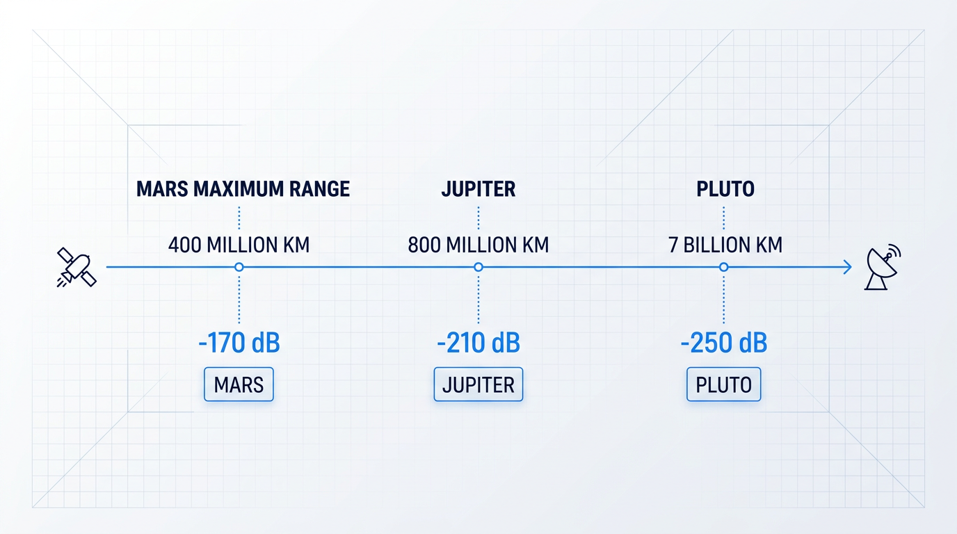
Consider what it takes to send a single bit of data from a spacecraft orbiting Jupiter back to Earth: the signal must survive a journey of roughly 800 million kilometres, arriving with so little energy that the receiving antenna must be among the most sensitive instruments ever built. The component that determines whether that bit makes it home — whether the science survives the crossing — is the deep space amplifier.
In engineering terms, a deep space amplifier is an electronic amplifier used in spacecraft or ground systems to transmit or receive RF or optical signals across interplanetary distances. The term is a mission-context definition, not a component-level one: it encompasses both spacecraft-side transmit amplifiers (the primary focus of most mission design) and the ground-segment receive amplifiers that form the other half of every deep space link.
Both RF and optical paradigms fall within scope. Current deep space missions rely almost exclusively on RF power amplifiers operating at microwave frequencies, but optical amplifiers operating at near-infrared wavelengths are an emerging and increasingly mission-relevant alternative — and both are covered in depth in this guide.
The Physics That Governs Everything
The foundational constraint of deep space communications is the inverse-square law: radiated signal power falls off with the square of the distance between transmitter and receiver. As the JPL DESCANSO monograph states directly, communications beams spread as the square of the distance — as the distance increases, the difficulty becomes quadratically more difficult.
At interplanetary distances, this produces free-space path loss figures that are almost incomprehensible by terrestrial standards. A Voyager-era link analysis documents a space loss of –290.54 dB at X-band for a range of 6.37 AU — a number representing the signal power being diluted across an area billions of times larger than the receiving antenna.
To put that in intuitive terms: a system capable of transmitting 10 gigabits per second from geosynchronous orbit (approximately 40,000 km) would, using the same hardware, achieve roughly 1 bit per second from Pluto or Neptune distances — a degradation of ten billion times, entirely attributable to the increase in range.
Why Deep Space Is a Different Engineering Discipline
Deep space amplifier requirements are not simply a scaled-up version of those for LEO or GEO satellite applications. The difference is qualitative, not merely quantitative — and it flows from three structural realities of deep space missions.
First, distances are measured in astronomical units rather than thousands of kilometres. The Mars mission distance ranges from roughly 2,000 times the Earth-to-GEO distance at closest approach to 10,000 times at solar conjunction — and missions to the outer planets push that ratio far higher still.
Second, spacecraft power is sourced from solar arrays whose output falls with the inverse square of heliocentric distance. At Jupiter (5.2 AU), solar irradiance is only about 3.7% of its value at Earth orbit; at Saturn (9.5 AU), it drops to roughly 1.1%. For missions beyond the asteroid belt, radioisotope thermoelectric generators (RTGs) become the practical power source, but RTG output is also finite and declines over time — the Galileo spacecraft's RTGs produced approximately 570 W at launch, declining at roughly 0.6 W per month. Both power architectures impose hard ceilings on the amplifier's transmit power allocation.
Third — and most consequential — there is no opportunity for repair or replacement once the spacecraft has departed Earth's vicinity.
A failed amplifier in LEO can potentially be remediated by a servicing mission or a software workaround. A failed amplifier beyond Mars orbit is mission-ending — there is no recovery. This single fact drives the entire qualification philosophy of the discipline.
Three Governing Constraints
Every deep space amplifier decision is shaped by three constraint families. These will be developed in full engineering detail in later sections; the definitions here establish the vocabulary the rest of the guide uses.
- SWaP: Size, weight, and power budgets are finite and competed for by every spacecraft subsystem. The amplifier must achieve its link performance within a tight, often inflexible allocation.
- Radiation environment: Interplanetary space exposes electronics to galactic cosmic rays and solar particle events. The primary concerns are cumulative total ionising dose (TID) and transient single-event effects (SEE).
- Qualification and flight heritage: The no-repair constraint demands rigorous environmental and radiation qualification, plus a strong engineering preference for components with documented on-orbit performance.
The concept of flight heritage deserves particular emphasis: in deep space procurement, a component's track record of surviving prior missions is treated as a genuine engineering criterion, not bureaucratic conservatism. When a failure beyond Mars orbit ends a mission, demonstrated on-orbit reliability carries real risk-reduction value that no amount of ground testing can fully replicate.
Two Amplifier Paradigms
This guide covers two technology families. The first is RF power amplifiers, operating at microwave frequencies — primarily X-band (8.4 GHz downlink) and Ka-band (31.8–32.3 GHz downlink for deep space missions) — which are used in virtually all current deep space spacecraft for the primary science downlink. Travelling wave tube amplifiers (TWTAs) and solid-state power amplifiers (SSPAs) are the two main RF device types; their relative merits are examined in detail in a later section.
The second paradigm is optical amplifiers, operating at near-infrared wavelengths of approximately 1550 nm, enabling laser communication terminals that offer fundamentally different performance characteristics. As the JPL DESCANSO lasercom monograph notes, the carrier frequency advantage of optical over Ka-band is enormous — roughly 200,000 GHz versus 32 GHz — with a theoretical link performance benefit that practical factors reduce but do not eliminate. Optical amplification for deep space is the emerging frontier; it is introduced here and examined in depth in a dedicated section later in this guide.
The spacecraft transmit amplifier does not operate in isolation: it is one half of a coupled link design. The Deep Space Network (DSN) — NASA's global network of large-aperture ground stations — forms the receive-side counterpart, and improvements to DSN receive sensitivity directly reduce the spacecraft EIRP requirement. That coupling is a central theme of this guide, and the DSN's ground-segment amplifier chain is covered in its own dedicated section.
With that foundation established — what a deep space amplifier is, why the physics of interplanetary distance makes it a categorically distinct engineering challenge, and what constraints govern its design — the next question is a specific one: what does all of this actually demand of the amplifier's output power?
The Deep Space Link Challenge
At Mars maximum distance from Earth — approximately 2.67 AU — a Ka-band signal travelling at the speed of light takes around 22 minutes to arrive. What actually arrives is almost incomprehensibly faint: JPL link budget analysis confirms a free-space path loss of approximately −295.9 dB at 37.25 GHz for that distance, and around −295.8 dB total path loss at 32 GHz. A transmitter producing tens of watts at the spacecraft delivers a received signal measured in fractions of a femtowatt at the ground terminal. That is not an engineering inconvenience — it is a hard physical reality that frames every decision about amplifier output power.
The quantity that governs whether a link closes at all is EIRP — Effective Isotropic Radiated Power — expressed in decibels relative to a milliwatt or watt. Conceptually, EIRP combines the transmitter's output power with the antenna's ability to concentrate that power in the direction of Earth, minus any losses between the two.
Every decibel of EIRP must come from somewhere on the spacecraft, and the three sources are genuine substitutes for one another — but each carries a distinct cost in mass, volume, and power.
- Transmit power (the amplifier): More RF output raises EIRP directly, but draws proportionally more DC power from the spacecraft bus and generates waste heat that must be radiated.
- Antenna gain (aperture size): A larger high-gain antenna concentrates power more tightly, but antenna diameter translates directly into mass, volume, and structural complexity.
- Coding and modulation efficiency: Advanced error-correction codes reduce the required received signal power, relaxing EIRP requirements — at the cost of processing complexity and additional power draw.
For a fixed EIRP target, the mission engineer can trade freely between these three levers. A larger antenna relaxes the amplifier requirement; a more efficient coding scheme relaxes both. The amplifier's output power is therefore not the only variable in the equation — but it is the one that competes most directly with the spacecraft's overall DC power budget.
Ka-band vs X-band: the frequency advantage
The deep space community has progressively migrated from X-band (8.4 GHz downlink) toward Ka-band (31.8–32.3 GHz downlink for deep space robotic missions) because of a fundamental consequence of the Friis transmission equation: link capacity scales, to first order, with the square of the operating frequency.
The theoretical gain from this frequency-squared relationship when moving from X-band to Ka-band is 11.6 dB — equivalent to a factor of roughly 14.5 in link capacity for the same spacecraft transmitter power and antenna size. This figure is confirmed across multiple JPL sources, including the IPN Progress Report atmospheric noise measurements at Goldstone and the Ka-band study documents from the TDA Planning Office.
| Parameter | X-band (8.4 GHz) | Ka-band (32 GHz) |
|---|---|---|
| Downlink frequency (deep space) | 8.4 GHz | 31.8–32.3 GHz |
| Allocated bandwidth (deep space) | ~50 MHz | 500 MHz |
| Theoretical frequency advantage over X-band | Baseline | +11.6 dB (~14.5×) |
| Practical net advantage (optimised link) | Baseline | +4.7 to +7.2 dB |
| Atmospheric noise sensitivity | Low | Higher — weather-dependent variability |
| Solar conjunction performance | Degrades at >2.3° SEP | Resilient to ~1° SEP; less scintillation |
Comparison of X-band and Ka-band deep space downlink parameters, grounded in JPL source material
In practice, the 11.6 dB theoretical advantage is reduced by atmospheric effects at the ground terminal — higher noise temperatures due to tropospheric moisture, rain attenuation, and the difficulty of maintaining antenna surface accuracy at Ka-band wavelengths. JPL analysis of optimised Ka-band links at DSN 34-metre beam-waveguide antennas at both Goldstone and Madrid found a practical net advantage over an optimised X-band link of between 4.7 dB and 7.2 dB, depending on the pass and the optimisation method used.
Even at the lower end of that range, 4.7 dB represents a factor of roughly three in data volume for the same spacecraft resources — a substantial return on the engineering investment required to operate at Ka-band. The 500 MHz of allocated bandwidth at Ka-band (compared to approximately 50 MHz at X-band) further amplifies this advantage for high-data-rate missions: Mars Reconnaissance Orbiter demonstrated X-band rates as high as 5.3 Mbps but was bandwidth-limited from going higher, a constraint that Ka-band largely removes.
The trade-off is atmospheric sensitivity: Ka-band ground terminals are more susceptible to weather-driven variability in system noise temperature and signal attenuation. The DSN's Ka-band link design must account for this variability explicitly — a topic developed further when examining the ground segment's role in the overall link budget.
From science data volume to required EIRP
The chain from mission science objectives to amplifier output power requirement is direct and quantifiable. A science mission's data volume requirement — how many gigabits of imagery, spectra, or instrument data must be returned per day — sets a required data rate for each communications pass.
That required data rate, combined with the link distance and the receiver's noise performance, determines the minimum received signal power needed to achieve a given Eb/N0 (energy per bit to noise spectral density ratio) at the DSN ground terminal. The required Eb/N0 depends on the coding scheme: modern LDPC codes used on Ka-band links can close a link with required Eb/N0 values as low as 1 dB, significantly relaxing the power requirement compared to older convolutional codes.
Working back through the path loss and ground antenna gain, the required received signal power translates directly into a required spacecraft EIRP. JPL's link analysis for Mars-to-Earth Ka-band links at 2.67 AU illustrates the scale: achieving 100 Mbps at maximum distance required spacecraft antenna apertures ranging from 3 to 9 metres and associated RF power requirements of 0.25 to 2.2 kW — figures that make clear why amplifier output power is a primary design driver, not a secondary consideration.
A mission returning housekeeping telemetry at a few kilobits per second faces a very different EIRP requirement than one attempting to return high-resolution radar imagery or hyperspectral data at tens of megabits per second. The sensitivity of the DSN ground terminal — its G/T, or antenna gain to system noise temperature ratio — also affects the required spacecraft EIRP: a more capable ground station relaxes the spacecraft's power requirement, which is why DSN aperture enhancements directly translate into mission science return.
At Jupiter (approximately 5.2 AU), solar intensity falls to roughly 3.7% of its value at Earth — meaning a solar array must be about 27 times larger to produce the same power as at Earth orbit. For missions that cannot carry an RTG, this makes amplifier DC-to-RF efficiency a primary spacecraft-level design constraint, not merely a thermal management consideration.
This solar flux relationship — confirmed by NASA Glenn and JPL solar power studies — has direct consequences for the amplifier. As established in the Background, signal intensity falls with the inverse square of distance. The spacecraft's available DC power shrinks by the same law as it travels further from the Sun. At Mars (~1.5 AU), solar flux is roughly 43% of its Earth-orbit value — a real constraint. At Jupiter (~5.2 AU), it falls to approximately 3.7% of Earth-orbit intensity, meaning a solar array must be roughly 27 times larger to deliver the same power.
An amplifier's DC-to-RF efficiency determines how much of that scarce bus power actually reaches the antenna feed as RF output. A Ka-band solid-state power amplifier demonstrating 15.4% power-added efficiency — as measured in early JPL Ka-band SSPA development work — draws over six watts of DC power for every watt of RF it produces. An X-band travelling wave tube amplifier with a DC-to-RF conversion efficiency around 40% draws roughly 2.5 watts per watt of RF output. The difference is not a datasheet footnote; at the scale of a deep space spacecraft's total power budget, it determines whether science instruments can operate simultaneously with the communications system.
The waste heat generated by amplifier inefficiency adds a further complication: in the vacuum of space, that heat cannot be convected away and must be radiated through dedicated thermal control surfaces. The thermal design implications of amplifier efficiency are substantial and will be examined in the engineering constraints section that follows.
Understanding why output power and DC-to-RF efficiency are the two dominant axes of deep space amplifier performance sets up the central question for the next section: which amplifier technology — travelling wave tube or solid-state power amplifier — best meets these requirements, and under what mission conditions does each hold the advantage?
TWTAs vs Solid-State Power Amplifiers: Technology Transition
Two fundamentally different physical mechanisms can produce RF gain on a deep space spacecraft — one rooted in vacuum electronics dating back to the mid-twentieth century, the other in the semiconductor revolution that followed. The travelling wave tube amplifier and the solid-state power amplifier each occupy a distinct region of the performance envelope, and understanding why requires looking at both how they work and how the industry learned, over decades, when to trust each one.
In a TWTA, gain originates from an interaction between an electron beam and an electromagnetic wave — no transistors involved. An electron gun at one end of the tube generates a focused, high-velocity beam of electrons.
The beam travels through a slow-wave structure — typically a helical coil of wire — that slows the RF wave down to approximately match the beam velocity. As the wave and beam travel together, energy transfers continuously from the beam to the wave, producing gain.
At the far end of the tube, the spent electron beam is collected and its remaining energy partially recovered by a multi-stage depressed collector, which applies progressively lower voltages to decelerate electrons in stages rather than wasting their kinetic energy as heat. This collector design is the key to TWTA efficiency at high frequencies.
An electronic power conditioner (EPC) converts the spacecraft bus voltage to the high voltages the tube requires — typically several kilovolts — and this EPC efficiency is factored into the overall system efficiency figure quoted for any TWTA.
SSPAs achieve gain through transistor action in solid-state semiconductor devices rather than through electron-beam physics. Historically built around GaAs MMIC (monolithic microwave integrated circuit) technology, newer designs increasingly use GaN MMIC devices, which offer higher power density and improved efficiency at microwave frequencies.
Because individual MMIC transistors produce only a few watts of RF output at Ka-band, reaching higher power levels requires power combining: multiple amplifier chains are combined through waveguide or hybrid combining networks, with each stage adding to the total output.
Like TWTAs, SSPAs require an EPC to condition the spacecraft bus voltage to the precise supply levels the MMIC stages demand. The modular, solid-state architecture makes SSPAs inherently more compact at lower power levels, where a single MMIC chain may suffice without combining.
Performance trade-offs: where each technology leads
The performance difference between the two approaches is most visible in efficiency and high-power output — the two axes that matter most when spacecraft power is scarce, as the link budget discussion established.
NASA Glenn Research Center measurements of space-qualified Ka-band TWTAs show the TWT tube alone achieving efficiency above 50%, with overall TWTA efficiency (including the EPC) reaching approximately 45% in flight units such as the LRO K-band TWTA, and the tube efficiency of the 200 W Ka-band model 999HA exceeding 60%. For Ka-band SSPAs, NASA Glenn research documents that the overall efficiency of high-power solid-state amplifiers — after accounting for MMIC circuit losses and power combining — is on the order of 15 to 20%, with GaN-based prototype single-ended amplifiers at Ka-band demonstrating power-added efficiency (PAE) of approximately 23%.
| Performance Axis | TWTA | SSPA (GaAs/GaN) |
|---|---|---|
| DC-to-RF Efficiency (Ka-band) | TWT tube: >50–60%; overall system (with EPC): ~45% | MMIC PA stage: ~25–30%; combined high-power system: ~15–20%; GaN prototype PAE: ~23% |
| High-Power Output Capability | 10 W to several hundred watts demonstrated; 200 W Ka-band space-qualified | Individual MMIC delivers ~2–3 W at Ka-band; combining required for higher power |
| Linearity Near Saturation | AM-AM and AM-PM nonlinearities require operating back from saturation | Generally better linearity; low EVM demonstrated with higher-order modulation (16QAM, 32APSK) |
| Bandwidth | Wide bandwidth across the operating band; helix designs cover the deep-space Ka allocation | Broadband capable; separate designs may be needed for widely separated bands |
| Mass Advantage | Comparable to SSPA at high power levels; EPC adds mass | Advantage at low power where single MMIC chain suffices; EPC still required |
Direct comparison of TWTA vs SSPA across key performance axes relevant to deep space amplifier selection, populated with figures from NASA Glenn Research Center and JPL DESCANSO sources.
The efficiency gap has direct consequences for spacecraft power budgets. A TWTA delivering 100 W of RF output at 45% overall efficiency draws roughly 222 W of DC power; an SSPA delivering the same output at 15–20% efficiency would draw 500–667 W — power that simply does not exist on most deep space spacecraft.
At lower power levels, the picture changes. GaN MMIC technology is closing the efficiency gap, and the simpler architecture of a single-chain SSPA without combining losses can be competitive in mass and power draw for applications where 15–25 W of RF output is sufficient.
The linearity advantage of SSPAs is real and matters for missions using spectrally efficient modulation. NASA Glenn prototype Ka-band GaN amplifiers have demonstrated low error vector magnitude (EVM below 6%) while amplifying higher-order waveforms including 16QAM and 32APSK — modulation schemes that a TWTA operating near saturation would distort without back-off that costs efficiency.
On-orbit reliability: what the fleet data shows
Reliability data has shaped the adoption trajectory of both technologies as much as raw performance has. The foundational fleet study in this area was published by Strauss (1993) in the International Journal of Satellite Communications, drawing on in-orbit data from 72 spacecraft covering 497 spacecraft-years of operation.
A key finding of that study was that SSPAs, while reliable, did not achieve the reliability of TWTAs — TWTAs were approximately one-third more reliable than SSPAs in the 1993 dataset, at comparable C-band power levels (6–16 W RF output). This result was influential: it gave mission planners a concrete data-based reason to be conservative about SSPA adoption in applications where reliability was paramount.
The picture has evolved since then. Subsequent Boeing fleet analyses — cited in multiple NASA Glenn technical memoranda as Weekley and Mangus (2005) and Nicol, Mangus, and Grebliunas (2008) — continued tracking TWTA versus SSPA on-orbit reliability as the SSPA fleet accumulated flight hours. The consensus across NASA sources is that TWTAs have demonstrated high on-orbit reliability at microwave frequencies, while the SSPA reliability picture has improved as flight heritage has accumulated and GaN technology has matured. This is an area where the data continues to evolve.
The 1993 Strauss fleet study — 72 spacecraft, 497 spacecraft-years — found TWTAs approximately one-third more reliable than SSPAs at comparable power levels. That single data point shaped deep space amplifier procurement conservatism for years.
Mission examples: the pattern in practice
The performance trade space is most legible when grounded in specific missions. The JPL DESCANSO monograph on deep space communications documents the amplifier choices for several representative missions, and the pattern is consistent.
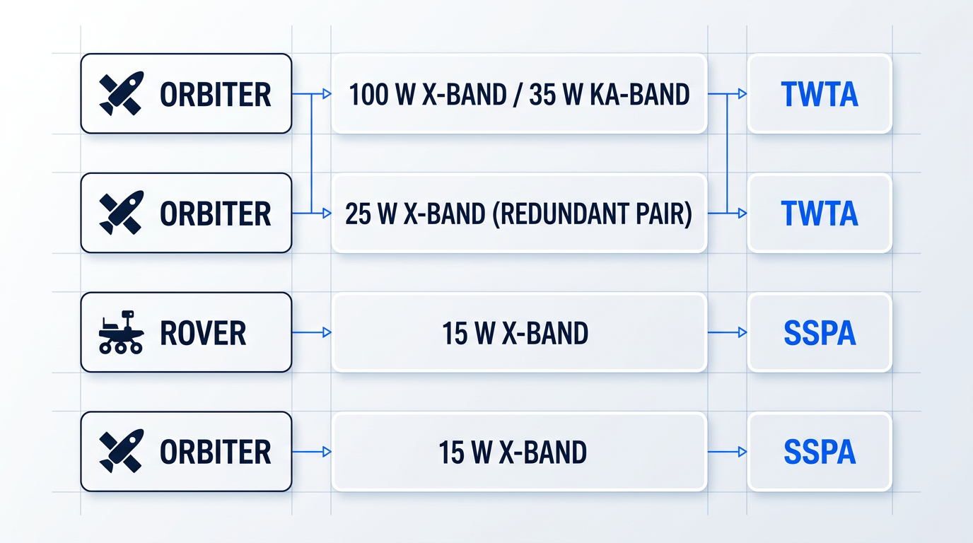
The Mars Reconnaissance Orbiter (MRO) carries a 100 W X-band TWTA and a 35 W Ka-band TWTA — a high-power mission where the output power and efficiency of vacuum electronics are the decisive factors. The DESCANSO documentation confirms the nominal TWTA RF output power as 100 W at X-band (102 W measured pre-launch) and 35 W at Ka-band (34 W measured).
Juno, operating at Jupiter, uses redundant 25 W X-band TWTAs from Tesat/Thales, requiring 56 W of DC input per unit — a mission where TWTA output power and long-duration reliability in a high-radiation environment are the governing requirements.
The Mars Science Laboratory (Curiosity) rover takes the opposite approach: its X-band transmitter is a 15 W SSPA, confirmed in the DESCANSO chapter on MSL telecommunications. The rover's mass and power constraints make the SSPA the right tool — the TWTA was reserved for the descent stage, which required 100 W during cruise and entry, descent, and landing.
The same SSPA design was carried forward to Perseverance, consistent with the same mass-constrained rover architecture. Mars Odyssey, an earlier orbiter, also used a 15 W X-band SSPA — a lower-power mission where the SSPA's mass and integration advantages were decisive.
The pattern across these missions is not that one technology is superior — it is that each occupies a different region of the mission design space. TWTA for high-power direct-to-Earth links from orbiters; SSPA for mass-constrained surface assets where moderate output power is sufficient.
The historical arc of the TWTA-to-SSPA transition — spanning decades, gated at every step by qualification data and accumulated flight hours rather than by raw performance claims — is the same dynamic now beginning to play out with optical communications for deep space links.
Understanding that arc, and why it moves at the pace it does, is the foundation for evaluating the engineering constraints that determine which technology a given mission can actually fly — the subject of the next section.
RF Amplifier Constraints: SWaP, Thermal, and Radiation
A datasheet tells you what an amplifier can do under ideal conditions. It says nothing about whether the amplifier can survive a seven-year transit to Jupiter, dissipate its waste heat into a vacuum, or continue functioning after absorbing years of galactic cosmic ray bombardment. For a deep space amplifier, the engineering constraints that govern hardware selection go well beyond peak output power or gain — they are the three constraint families of SWaP budgets, thermal management in vacuum, and radiation tolerance, and any one of them can rule out an otherwise capable device.
SWaP: The Spacecraft Power and Mass Budget
The RF subsystem's mass and power allocations are not set by the amplifier engineering team in isolation — they emerge from a spacecraft-level resource negotiation in which the amplifier competes directly with the high-gain antenna, the transponder, power conditioning electronics, and the science instruments that justify the mission.
This competition is real and consequential: a heavier or less efficient amplifier does not simply cost mass on paper, it displaces science payload or reduces propellant margin, with direct effects on mission return.
The key amplifier-side figure of merit within this budget is DC-to-RF conversion efficiency, sometimes expressed as power-added efficiency (PAE).
At large heliocentric distances, solar flux falls with the inverse square of distance from the Sun, so the power budget available to the entire spacecraft shrinks dramatically as the mission progresses outward — every watt drawn by the amplifier is a watt unavailable for housekeeping, thermal control, or instruments.
NASA Glenn Research Center data illustrates the stakes: a Ka-band TWT developed for deep space missions demonstrated 200 W output at 60% efficiency with a mass of just 1.5 kg, compared with the Cassini-Huygens Ka-band TWT which produced 10 W at 41% efficiency and 0.75 kg — a factor-of-ten improvement in the power-to-mass figure of merit over that generation.
That improvement matters because the spacecraft power budget for a 1 Gbps deep space link can approach 100 kg in combined power subsystem mass — a burden that makes amplifier efficiency a first-order mission design parameter, not an engineering preference.
Thermal Management in Vacuum
A terrestrial amplifier sheds waste heat through convection: air moves across the device, carries heat away, and the problem is manageable with a fan or a heatsink. In deep space, there is no air.
In vacuum, heat can only leave the amplifier by conduction through a thermal interface to the spacecraft structure, and then by radiation from a dedicated radiator surface — a two-step path that imposes strict limits on how much power can be dissipated and how quickly.
The challenge scales with output power: high-power TWTs generate waste heat equal to roughly half of their input DC power, with the majority appearing at the collector end of the tube, and that heat must travel from the collector through a mechanical conduction path to the radiator.
For solid-state amplifiers, the critical thermal node is the semiconductor junction temperature, which directly governs device lifetime through Arrhenius-type degradation mechanisms — elevated junction temperatures accelerate the chemical and physical processes that degrade semiconductor materials over time.
NASA preferred reliability practices for deep space missions have historically required that junction temperatures be maintained below 110°C under worst-case operating conditions, with the reliability benefit of lower temperatures being substantial: a 25°C reduction in junction temperature can improve theoretical reliability by an order of magnitude.
On a spacecraft that cannot be serviced, this is not a conservative design preference — it is the engineering basis for mission success over a multi-year operational lifetime.
Thermal cycling introduces a related but distinct reliability challenge: deep space spacecraft transit between eclipse and sunlit phases, subjecting the amplifier packaging to cyclic temperature swings that impose mechanical stress on solder joints, bond wires, and ceramic packages.
Solder joint fatigue from differential thermal expansion — a failure mode documented on Magellan and Galileo flight hardware — is a classical metal fatigue mechanism whose severity is an extremely strong function of the temperature swing magnitude and the number of cycles accumulated over the mission lifetime.
This is precisely why space-qualified amplifiers use hermetic ceramic packaging, robust bonding techniques, and matched thermal expansion materials — design choices that add cost and complexity compared with commercial equivalents but are essential for reliability over thousands of thermal cycles.
Radiation Tolerance: TID and Single-Event Effects
Beyond the Van Allen belts, the radiation environment is fundamentally different in character from that experienced in low Earth orbit.
In LEO, trapped electrons and protons in the Van Allen belts dominate the dose environment. In interplanetary space, the primary threats are galactic cosmic rays (GCRs) — highly energetic, heavy-ion particles originating outside the solar system — and solar particle events (SPEs), which deliver intense bursts of high-energy protons during periods of solar activity.
GCRs are particularly challenging because their high energies make them extremely difficult to shield against: even substantial aluminium shielding provides limited attenuation for the highest-energy cosmic ray particles.
Total ionising dose (TID) is the cumulative effect of ionising radiation on semiconductor devices, causing progressive parametric degradation — threshold voltage shifts, increased leakage currents, and ultimately functional failure — as charge accumulates in device oxide layers over the mission duration.
For SSPA device selection, the radiation sensitivity profiles of GaAs and GaN MMIC devices differ in ways that constitute a genuine technology trade-off.
GaN HEMTs with Schottky gate designs have demonstrated TID tolerance to approximately 6 Mrad(Si) under gamma irradiation, and their displacement damage dose (DDD) performance is roughly an order of magnitude better than GaAs HEMTs — a meaningful advantage for missions accumulating significant particle fluence over multi-year transit times.
However, GaN HEMTs introduce a different vulnerability: because they have no gate oxide in the conventional sense, TID effects are relatively benign, but single-event effects (SEEs) — particularly leakage current degradation and single-event burnout driven by ion interaction near the gate — represent the more significant radiation risk for these devices.
SEEs are categorically distinct from TID: rather than cumulative degradation, they are discrete events caused by a single energetic particle passing through or near a sensitive node in the circuit, with consequences ranging from recoverable upsets to permanent destructive failure through mechanisms such as single-event latchup (SEL), single-event gate rupture (SEGR), and single-event burnout (SEB).
For power amplifier devices operating at high drain-to-source voltages, SEE susceptibility tends to increase with voltage rating, making the selection of appropriate operating margins and device types a critical part of the radiation hardness assurance process.
Three principal strategies are used to manage radiation risk, each with distinct trade-offs:
- Shielding: Adding aluminium or graded-material shielding around sensitive devices reduces TID from electrons and low-energy protons, but provides limited protection against high-energy GCRs and adds mass.
- Radiation-hardened device selection: Choosing parts from processes or device families with demonstrated tolerance at the required TID and SEE levels, verified through existing test data from qualified sources.
- Lot-specific radiation testing: Testing samples from the actual production lot used in the flight unit, because radiation sensitivity can vary between lots even from the same fabrication process.
The interaction between these strategies is important: even a device from a radiation-hardened process can exhibit lot-to-lot variability in TID sensitivity, as demonstrated in ESA JUICE programme test data showing measurable differences in parametric degradation across date codes from the same manufacturer.
This is why lot-specific radiation testing — formally known as radiation lot acceptance testing (RADLAT) — remains a requirement on high-consequence programmes even when a device carries a radiation-hardened designation: the hardness assurance data for the specific flight lot is what actually bounds the risk.
When a deep space spacecraft cannot be serviced or recovered, preferring a component with documented on-orbit performance and radiation test data over a higher-performing but unflown device is not conservative — it is the correct engineering decision. The value of demonstrated reliability is real and quantifiable: an unflown device with superior datasheet performance offers no evidence of how it behaves after years in the interplanetary radiation environment, whereas a flown device with heritage data does.
When a single TWTA or SSPA cannot meet the link requirement on its own, waveguide power combining provides a well-established path to higher effective output power.
The standard approach uses a magic-T hybrid junction combiner: two amplifiers feed the E-plane and H-plane input ports of the magic-T, the signals add in phase at the sum port, and the combined output drives the antenna feed — with the high isolation between input ports (typically greater than 30 dB) preventing the two amplifiers from loading each other.
NASA Glenn Research Center demonstrated this technique at Ka-band using two 100 W TWTAs operating over the 31.8 to 32.3 GHz deep space frequency band, achieving a combined output of approximately 180 W with a combining efficiency of up to 90% — corresponding to an insertion loss of roughly 0.5 dB for the two-way combiner.
The architecture is readily extensible in a binary configuration — combining 4, 8, or more amplifiers — and has been demonstrated to support data transmission rates well above the current deep space state of the art, making it an established technique rather than a speculative approach.
With the spacecraft transmit chain now fully characterised — from SWaP budgets and thermal design through radiation hardness assurance and power combining — the next consideration is the other end of the link: the ground-segment receive chain, where the Deep Space Network's cryogenically cooled low-noise amplifiers must recover signals that arrive at vanishingly small power levels after crossing hundreds of millions of kilometres.
DSN Ground LNAs: The Receive Chain Explained
The spacecraft transmit amplifier is only half the story. A signal that departs a deep space probe at tens of watts of RF power arrives at Earth as a whisper measured in fractions of a femtowatt — and the engineering challenge of catching that whisper without burying it in thermal noise is every bit as demanding as the challenge of generating it in the first place.
The ground segment's contribution to link performance is captured in a single figure of merit: G/T, defined as antenna gain divided by system noise temperature. Just as spacecraft EIRP quantifies the transmit chain's contribution to the link budget, G/T quantifies the receive chain's contribution — and the two are directly interchangeable in the link equation.
Within the system noise temperature budget, the low-noise amplifier (LNA) is the dominant contributor. Because noise introduced by the first active element in a receive chain is amplified by every subsequent stage, the noise temperature of the LNA sets a practical floor on everything that follows — making LNA technology the central engineering challenge of the DSN receive chain.
Two LNA Technologies: Masers and Cryogenic HEMTs
The DSN has historically operated two classes of LNA technology: travelling-wave masers (TWMs) and cryogenic InP HEMT LNAs based on indium phosphide high electron mobility transistors.
Masers have been used in the DSN since its inception and operate at physical temperatures near the boiling point of liquid helium (approximately 4.5 K), requiring complex JPL-designed closed-cycle refrigeration systems. HEMT LNAs operate at a higher physical temperature — around 12–15 K — using a simpler, more reliable closed-cycle refrigerator.
JPL-developed InP HEMT modules have demonstrated noise temperatures of 3.5 K at 8.4 GHz (X-band) and 8.5 K at 32 GHz (Ka-band). Front-end receiver packages using these modules achieved operating system noise temperatures of 17 K at 8.4 GHz on a 70-m Cassegrain antenna and 39.4 K at 32 GHz on a 34-m beam waveguide antenna, both at zenith.
The Ka-band TWM design documented in JPL TMO Progress Report 42-159 targets operation in a 4-K Gifford-McMahon refrigerator and estimates a maser noise temperature of approximately 5.3–6.0 K at the cryogenic input — lower than the InP HEMT Ka-band figure of 8.5 K, but at the cost of substantially more complex cryogenic infrastructure.
| Technology | Frequency Band | LNA Module Noise Temp. | Physical Temp. | System Noise Temp. (on antenna, zenith) |
|---|---|---|---|---|
| InP HEMT LNA | X-band (8.4 GHz) | 3.5 K | 12–15 K (hydrogen CCR) | 17 K (70-m Cassegrain, zenith, clear) |
| InP HEMT LNA | Ka-band (32 GHz) | 8.5 K | 12–15 K (hydrogen CCR) | 39.4 K (34-m BWG, zenith, clear) |
| Travelling-Wave Maser (TWM) | Ka-band (32 GHz) | ~5.3–6.0 K (design estimate) | ~4.0 K (GM refrigerator) | Not published; lower than HEMT module figure |
Comparison of InP HEMT LNA and Ka-band TWM noise temperature performance at DSN operating frequencies, showing module noise temperature, physical operating temperature, and demonstrated system noise temperature on-antenna.
The table makes the trade-off explicit: at Ka-band, the TWM design offers a lower module noise temperature than the InP HEMT LNA, but no published system-level noise temperature for a DSN Ka-band TWM installation is available in the primary sources — the Ka-band TWM described in TMO 42-159 was a design study, not a deployed system. At X-band, the InP HEMT has achieved 17 K system noise temperature on a 70-m antenna, a figure that represents the operational state of the art.
The first HEMT LNA prototype was installed in the DSS-13 feedcone at Goldstone in August 1986, replacing the 2.3-GHz maser and delivering a system noise temperature of 31.5 K versus the maser's 28.7 K — a modest penalty judged acceptable given the HEMT system's lower cost, higher reliability, and simpler cryogenic infrastructure.
That transition mirrors the TWTA-to-SSPA shift on the spacecraft side: in both cases, the incumbent vacuum-tube technology offered marginally superior noise performance, but the solid-state alternative offered operational advantages compelling enough to drive adoption across the network over time.
System Noise Temperature: Beyond the LNA
The LNA noise temperature is only one term in the full system operating noise temperature. The DSN 810-005 Handbook defines it as the sum of the antenna-microwave system noise temperature and the sky noise temperature, where sky noise combines atmospheric noise and the attenuated cosmic microwave background.
Atmospheric noise, antenna spillover past beam-waveguide mirrors, feed losses, and cosmic background all contribute — and their relative magnitudes shift significantly between X-band and Ka-band.
At X-band (8.4 GHz), zenith atmospheric noise temperature at Goldstone is typically 2–3 K under clear conditions, rising modestly with weather — a contribution that is small relative to the LNA and feed terms and largely predictable for link margin purposes.
At Ka-band (32 GHz), the picture is fundamentally different. DSN 810-005 Module 105 documents Ka-band zenith atmospheric noise temperatures at Goldstone ranging from approximately 6.7 K under minimum-weather conditions to over 25 K at 90% cumulative distribution — and at lower elevation angles, atmospheric contributions can exceed 60 K.
This weather sensitivity is a direct consequence of Ka-band's higher frequency: atmospheric effects increase with frequency, and water vapour and cloud liquid water are substantially more absorbing at 32 GHz than at 8.4 GHz. Mission designers using Ka-band must carry additional link margin to account for this variability, or employ adaptive data rate strategies to maintain throughput during adverse weather.
A 1 dB improvement in ground G/T translates directly into a 1 dB reduction in required spacecraft EIRP. The spacecraft power amplifier and the ground LNA are coupled design decisions — optimising one end of the link can substitute for investment at the other. Spacecraft amplifier selection cannot be made in isolation from knowledge of the ground segment's receive performance.
This coupling has practical procurement implications. A mission that can guarantee access to a high-G/T DSN antenna configuration can afford a lower-power spacecraft amplifier; conversely, a mission constrained to a smaller aperture or a degraded weather site must compensate with higher spacecraft EIRP.
DSN Antenna Configurations and G/T Reference Values
The DSN operates two primary aperture classes relevant to deep space mission design: the 34-m beam waveguide (BWG) antennas and the 70-m antennas. Each complex at Goldstone, Canberra, and Madrid maintains one 70-m antenna and three to four 34-m BWG antennas.
According to the DSN Services document (820-100), the 34-m BWG antennas provide a G/T of approximately 54.2 dB at X-band and 61.1 dB at Ka-band deep space (at 45-degree elevation, diplexed configuration, 90% weather). The 70-m antenna achieves approximately 61.5 dB at X-band — roughly 7 dB above a single 34-m BWG at that band.
The DSN 810-005 Handbook notes that Ka-band G/T values vary across the network — spanning roughly 60 to 62.5 dB for 34-m BWG antennas — largely because of the much lower atmospheric noise contribution at Goldstone compared with Canberra and Madrid, confirming that ground station weather is a first-order variable in Ka-band link performance.
Unlike the spacecraft amplifier, the ground LNA operates without the SWaP constraints or radiation environment that govern flight hardware design — which is precisely why cryogenic cooling to near absolute zero is feasible on the ground but impractical on a spacecraft.
The RF receive chain described here — a large dish antenna feeding a cryogenically cooled LNA operating at noise temperatures measured in single-digit Kelvin — represents the state of the art in radio-frequency receive sensitivity. The next section examines a paradigm that replaces this entire architecture with something fundamentally different: a large-aperture telescope and a photon-counting detector optimised for laser wavelengths rather than radio waves.
Optical Amplifiers for Deep Space: How EDFAs Enable Laser Communications
The RF discussion so far has covered both ends of the deep space link — the spacecraft transmit chain and the DSN receive chain. Optical communications replaces both with an entirely different physical layer, one where the efficiency advantage is not incremental but structural: it is written into the laws of physics at the level of carrier frequency.
As confirmed in the DESCANSO Monograph Series 7 link design analysis, optical carriers operate at approximately 200–300 THz, compared to roughly 32 GHz for Ka-band deep space RF links — a ratio of around 6,000 to one at the lower end of that optical range.
Higher carrier frequency means narrower beam divergence: antenna gain scales inversely with the square of wavelength, so an optical aperture concentrates energy into a far tighter cone than any practical RF antenna can achieve at interplanetary distances.
The practical consequence, as the DESCANSO Chapter 2 analysis frames it, is that an optical link can achieve a higher data rate than a comparable RF system while operating at lower transmit power and with a smaller aperture — not because of engineering cleverness, but because the physics of diffraction works in its favour at shorter wavelengths.
A 1550 nm optical carrier operates at roughly 200 THz versus 32 GHz for Ka-band — a factor of approximately 6,000 in carrier frequency. This is the same physical relationship that gives Ka-band its advantage over X-band, extended orders of magnitude further.
How an EDFA Amplifies Light
The amplifier technology that makes 1550 nm deep space laser communications practical is the erbium-doped fibre amplifier (EDFA) — a device that amplifies an optical signal directly, without converting it to an electrical signal and back.
The gain medium is a length of optical fibre whose core has been doped with erbium ions.
A separate pump diode — operating at either 976 nm or 1480 nm, depending on the design — injects pump light into the fibre, exciting the erbium ions into a higher energy state and establishing population inversion.
When the 1550 nm signal photons travel through this inverted medium, they trigger stimulated emission: each signal photon causes an excited erbium ion to release an identical photon, amplifying the signal coherently.
The contrast with RF amplification is the conceptual bridge worth pausing on: where a travelling wave tube amplifier (TWTA) achieves gain through electron-wave interaction in a vacuum, and a solid-state power amplifier (SSPA) achieves it through transistor gain stages, an EDFA operates entirely on photons through stimulated emission in a doped fibre medium.
The 1550 nm operating wavelength falls within the C-band telecom window — a fortunate alignment that means the component ecosystem (pump diodes, doped fibres, fibre couplers) is mature and commercially available, which the NTRS Spellmeyer paper identifies as a key factor in optimising performance, cost, and reliability for space laser communications hardware.
The MOPA Architecture in Deep Space Laser Terminals
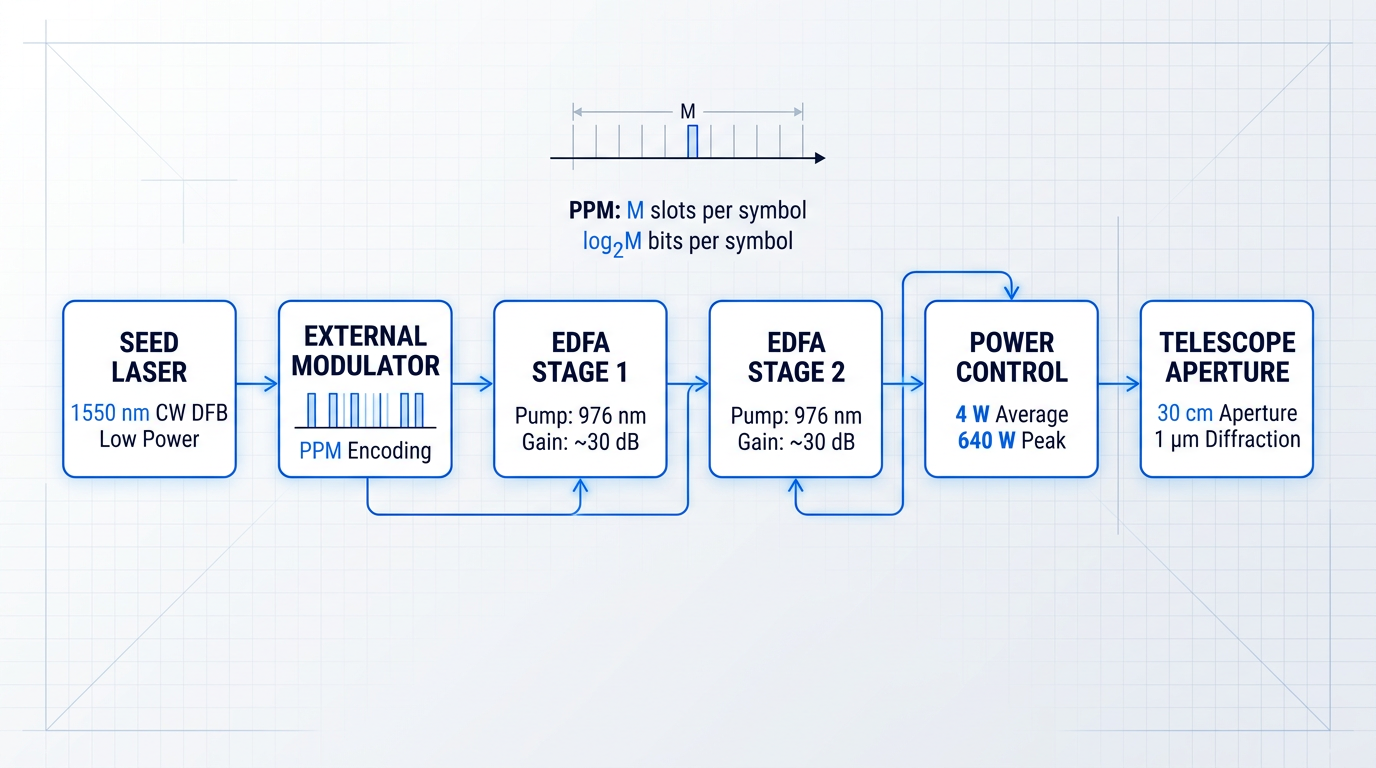
No single laser oscillator has been identified that can directly generate the high-peak-power, precisely modulated output required for deep space optical links — which is why the master-oscillator power amplifier (MOPA) architecture has become the standard approach for flight laser transceivers.
In a MOPA transmitter, a seed laser (typically a continuous-wave distributed feedback semiconductor laser with an external modulator) generates the modulated signal at low power, preserving modulation quality and extinction ratio.
One or more EDFA stages then amplify the signal to the required output power level — for the Deep Optical Terminals (DOT) flight laser transceiver design described in JPL's TMO Progress Report 42-185, the design target was a 4 W average power output at 1550 nm.
The MOPA chain is the optical counterpart to the transponder-plus-power-amplifier architecture in RF systems: the seed laser plays the role of the exciter, and the EDFA stages play the role of the power amplifier.
Pulse position modulation (PPM) is the modulation format of choice for deep space optical links, confirmed across multiple JPL technical sources including the DESCANSO Chapter 2 link design analysis.
PPM works by dividing each symbol period into M time slots and placing a single pulse in one slot — conveying log₂M bits per symbol while achieving a peak-to-average power ratio equal to M.
This high peak-to-average ratio is the key: it allows the receiver to detect individual photons against background noise, making the link photon-efficient rather than average-power-limited.
The DOT FLT design described in TMO Progress Report 42-185 used PPM orders from 16 to 128 slots per symbol, with the resulting laser transmitter peak-to-average power ratios ranging from 20:1 to 160:1 — and a peak power on the order of approximately 640 W from a 4 W average power transmitter.
Engineering Challenges in Space EDFA Transmitters
Achieving watt-class average power and hundreds of watts of peak power from a fibre amplifier in a space environment introduces engineering challenges that have no direct equivalent in RF power amplifier design.
The most prominent nonlinear constraint in single-mode fibre is stimulated Brillouin scattering (SBS): at high peak power, the optical field couples to acoustic phonons in the fibre, generating a backward-propagating wave that limits how much peak power can be pushed through the fibre before signal degradation becomes severe.
Stimulated Raman scattering (SRS) is a related nonlinear effect that transfers energy from the signal wavelength to longer-wavelength Stokes modes, also setting an upper bound on useful peak power in single-mode fibre.
The standard mitigation for both effects is large-mode-area (LMA) fibre, often co-doped with erbium and ytterbium (Er-Yb): the larger effective mode area reduces the optical intensity at a given power level, raising the nonlinear threshold.
The DOT FLT design described in TMO Progress Report 42-185 used large-mode-area co-doped Er-Yb fibre amplifiers specifically for the high-power sections of the transmitter, with the fibre pumped by 976 nm multimode pump diodes that were derated to increase their operational lifetime.
Pump diode reliability is the dominant long-term reliability concern for EDFA-based space transmitters — a point made explicitly in the Spellmeyer NTRS paper, which identifies single-mode 980 nm pump laser diodes as typically the largest factor in determining long-term reliability for double-pass amplifier designs.
The radiation sensitivity of EDFAs and Er-Yb-doped fibre amplifiers in the space environment compounds this concern: published studies confirm that commercial rare-earth-doped fibres are highly sensitive to ionising radiation, with gain degradation increasing with deposited dose — the same radiation environment discussed in the spacecraft SWaP and radiation tolerance section applies directly to the optical amplifier's pump and signal fibre.
- Stimulated Brillouin Scattering: Backward-propagating acoustic coupling limits peak power in single-mode fibre; primary nonlinear constraint for narrow-linewidth pulsed transmitters.
- Stimulated Raman Scattering: Energy transfer to longer-wavelength Stokes modes sets a secondary peak-power ceiling in single-mode fibre amplifiers.
- LMA Er-Yb Fibre Mitigation: Large-mode-area co-doped fibre raises the nonlinear threshold by reducing optical intensity at a given power level; standard for high-power space transmitters.
- Pump Diode Radiation Sensitivity: 976 nm or 1480 nm pump diodes face ionising radiation degradation; their output power decline directly reduces amplifier gain over mission lifetime.
These four challenges are interdependent: the choice of LMA fibre geometry affects the nonlinear threshold, the pump wavelength affects radiation sensitivity (published studies note that 1480 nm pump wavelengths show lower radiation-induced attenuation than 980 nm, though space-qualified diodes currently exist only at 980 nm), and pump derating affects both reliability and available gain.
Pointing, Acquisition, and Tracking
The narrow beam divergence that makes optical links efficient also makes them the most demanding pointing problem in deep space communications engineering.
As the DESCANSO Chapter 5 analysis notes, a 30 cm transmitter aperture operating at 1 µm wavelength produces a diffraction-limited beam with a 3 dB full width of approximately 3 µrad — compared to millidegrees for a Ka-band high-gain antenna.
The DOT FLT design in TMO Progress Report 42-185 required 0.91 µrad 1-sigma pointing stability for the transmit beam, and 2 µrad 1-sigma for the receive beam — requirements that are orders of magnitude more stringent than for any RF system.
Meeting these requirements demands a pointing, acquisition, and tracking (PAT) subsystem — combining coarse pointing (from the spacecraft attitude control system), a fast-steering mirror for fine pointing correction, and in some architectures an uplink beacon from the ground station to provide a pointing reference.
The critical systems-level point is that the EDFA is one component in a system where the PAT subsystem is equally enabling: a perfectly optimised amplifier delivering the correct average and peak power to the telescope is useless if the beam misses the ground receiver by even a few microradians.
Atmospheric Constraints at the Ground Terminal
RF signals penetrate cloud cover with manageable attenuation; optical links do not.
As the DESCANSO Monograph Series 7 full version states explicitly, cloud attenuation can be as high as several tens of decibels — far beyond any practical link margin — and optical communications generally requires a cloud-free line of sight to operate.
The operational response is ground station diversity: a network of geographically separated ground stations, positioned so that at least one has clear sky when others are clouded over.
The DESCANSO analysis of multi-site optical network design found that with nine sites each having 67 percent individual weather availability, the network can achieve approximately 96 percent combined availability — approaching the roughly 90 percent historically achieved by RF deep space links.
Atmospheric turbulence also affects optical links even under clear-sky conditions, causing signal scintillation and pointing-induced fades; adaptive optics at the ground receiver and data interleaving protocols are the engineering responses, as confirmed by both the DESCANSO analysis and operational experience from NASA's Laser Communications Relay Demonstration (LCRD).
With the operating principles of EDFAs, the MOPA architecture, PPM modulation, and the PAT and atmospheric constraints now established, the next section examines how these technologies have been demonstrated in practice — through NASA and ESA deep space optical communications programmes that have moved from engineering analysis to on-orbit operation.
NASA and ESA Deep Space Optical Communications Programmes
In November 2023, NASA's Deep Space Optical Communications (DSOC) experiment crossed a threshold no optical communications system had crossed before: it sent data via laser from beyond the Earth-Moon system, demonstrating for the first time that optical links are viable at interplanetary distances.
The flight hardware aboard the Psyche spacecraft is the direct realisation of the MOPA architecture described in the preceding section — a 22 cm aperture off-axis Gregorian telescope coupled to a 4 W average power, 1550 nm fibre laser MOPA with a peak power of approximately 640 W, designed to transmit pulse-position-modulated data to Earth across distances of up to 2.7 AU.
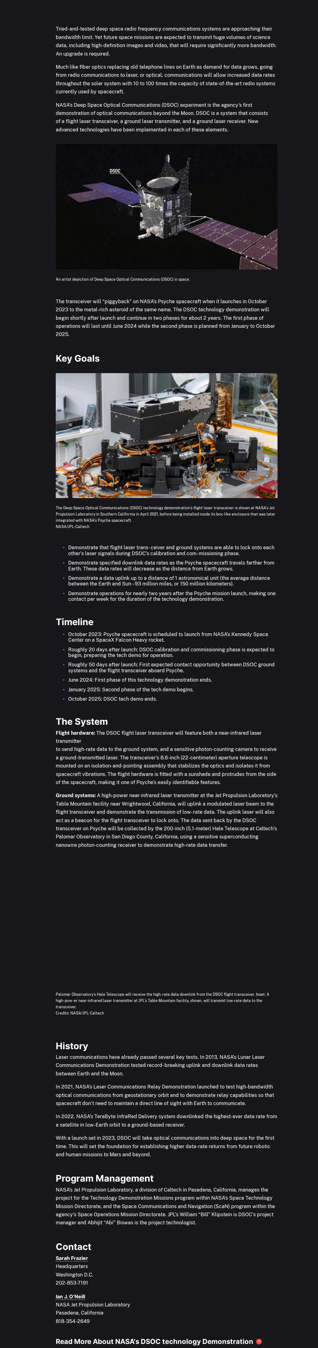
On the ground, the primary downlink receiver is the photon-counting superconducting nanowire single-photon detector (SNSPD) system installed at the 5.1 m Hale Telescope at Caltech's Palomar Observatory, while JPL's Table Mountain facility provides the uplink laser beacon — both are research-grade assets repurposed for the demonstration, not purpose-built operational infrastructure.
The performance milestones DSOC achieved across its operational life show clearly how data rate scales with distance — and how that rate compares to the best RF link previously demonstrated from a Mars mission.
| Distance | Data Rate Achieved | Notes / Comparison |
|---|---|---|
| ~16 million km (Nov 2023) | First light — link established | First optical comms demonstration beyond the Earth-Moon system |
| ~31 million km (~19 million miles, Dec 2023) | 267 Mbps (maximum) | System peak rate; comparable to household broadband download speeds |
| ~226 million km (~140 million miles, Apr 2024) | 25 Mbps | 1.5× Earth-Sun distance; far exceeded the 1 Mbps project goal at this range |
| ~390 million km (~240 million miles, Jun 2024) | 8.3 Mbps (maximum) | ~2.5× Earth-Sun distance; sustained rate of 6.25 Mbps also recorded |
| MRO Ka-band RF (Mars mission best) | 6 Mbps | Highest Ka-band rate from any Mars mission; achieved during early cruise phase |
Comparison of DSOC optical link performance milestones at increasing distances, with MRO Ka-band RF as the reference baseline.
The pattern is clear: data rate falls with distance, as link budget physics predicts, dropping from 267 Mbps at 31 million km to 8.3 Mbps at roughly 390 million km — yet even at that extreme range, the optical link matches or exceeds the 6 Mbps best-ever RF rate achieved by the Mars Reconnaissance Orbiter's Ka-band transmitter.
This comparison is not incidental: NASA's own documentation describes DSOC as designed to demonstrate data rates 10 to 100 times faster than radio frequency systems at comparable spacecraft mass and power — and the measured results validate that design objective across multiple distances.
ESA's Parallel Ground-Segment Development
Deep space optical communications is not a solely American effort: ESA ran a four-link campaign with DSOC over the summer of 2025, using the ESA Transportable Optical Ground Station (ETOGS) — a ground laser transmitter integrated into a standard 6 m shipping container and deployed at the Kryoneri Observatory in Greece.
All four links were successful, with the campaign reaching distances of over 300 million km; the final link pushed past two astronomical units, with ESA's ground laser receiver at the Helmos Observatory — 37 km from Kryoneri — capturing the return signal from Psyche at data rates up to 1.8 Mbps.
The ETOGS campaign demonstrates that ground-segment development for deep space optical communications is proceeding internationally, with European mission engineers now having demonstrated the ability to close an optical link from their own soil to a spacecraft hundreds of millions of kilometres away.
Taken together, the DSOC and ETOGS results support three conclusions that the data, rather than aspiration, now underwrite.
- PAT problem solved at scale: Pointing, acquisition, and tracking of a sub-arcsecond optical beam across interplanetary distances has been demonstrated repeatedly and reliably by both NASA and ESA ground segments.
- EDFA transceivers survive flight: The MOPA-based flight laser transceiver operated as designed throughout the demonstration, confirming that EDFA-based hardware can endure the space environment and perform at interplanetary ranges.
- Rate advantage over Ka-band is real: Optical links delivered data rates 10–100× higher than Ka-band RF at comparable spacecraft mass and power — a design goal now confirmed by measured flight data.
Those three conclusions represent what DSOC has proved; what it has not yet resolved is equally important for any engineer evaluating optical hardware for a future mission.
DSOC demonstrated two things simultaneously: that EDFA-based flight transceivers can survive deep space and operate as designed, and that the pointing, acquisition, and tracking problem is solvable at interplanetary distances. Either result alone would be notable; together, they remove the two largest engineering unknowns that separated optical deep space communications from credible mission readiness.
The results above are real and significant — but they do not resolve every challenge standing between a technology demonstration and a routine operational capability.
- Cloud cover blocks links entirely: Unlike RF, optical signals cannot penetrate cloud cover. A single ground station cannot guarantee availability — a global network of sites is required for operational link continuity.
- Atmospheric turbulence degrades quality: Even in clear conditions, turbulence causes scintillation and wavefront distortion, reducing link margin and requiring adaptive optics or aperture-averaging mitigation.
- No operational ground infrastructure: The Hale Telescope and Table Mountain facility are research assets. A global network of large-aperture dedicated optical ground stations for deep space does not yet exist.
- SNSPDs require cryogenic cooling: The superconducting nanowire single-photon detectors used in photon-counting receivers operate near 1 K and are not yet operational-grade instruments outside research settings.
- Qualification timeline is long: As with the TWTA-to-SSPA transition, converting a successful technology demonstration into routine mission hardware requires years of qualification data accumulation.
With the engineering case for optical deep space communications now established in flight, the question for mission engineers and procurement professionals becomes how both RF and optical hardware are qualified for mission use — the subject the next section addresses directly.
Qualification and Procurement Standards for Deep Space Amplifiers
Understanding what a GaN SSPA or an EDFA-based laser transceiver is capable of is not the same as knowing how to procure one for flight. The qualification hierarchy, the governing specifications, the flight heritage criterion, and the supplier landscape are the practical bridge between technical understanding and procurement action — and failing to account for them at programme inception is one of the most reliable sources of late-stage cost and schedule surprises in space hardware development.
Space hardware qualification is not a single gate but a layered hierarchy: component-level radiation and environmental testing feeds into subsystem-level thermal vacuum, vibration, and shock testing, which in turn feeds into mission-level acceptance testing. Each level adds cost and schedule, and each level can surface failures that require redesign at the level below.
MIL-PRF-38534 and ECSS: The Governing Standards Frameworks
For US government and NASA deep space missions, the primary specification governing the hybrid microelectronics used in space-qualified RF amplifier modules is MIL-PRF-38534. It establishes performance requirements for hybrid microcircuits — the packaging technology at the heart of space-qualified amplifier modules — and defines seven quality assurance levels, of which Class K (space application) and Class H (standard military) are the most relevant to deep space procurement.
Class K is the highest reliability level in the specification, intended specifically for space applications. It imposes more stringent test flows than Class H — including 100% non-destructive bond pull testing and tighter percent defective allowance (PDA) limits of 2% versus 10% for Class H — which directly translates into higher unit cost and longer lead time.
The procurement gateway for Class K components is the Qualified Manufacturers List (QML) maintained by DLA Land and Maritime. A component from a QML-listed manufacturer, built and tested to MIL-PRF-38534 Class K and bearing the appropriate certification mark, is the standard procurement baseline for NASA deep space missions. Procuring outside the QML requires explicit programme justification and additional qualification evidence.
For missions involving ESA or European prime contractors, the parallel framework is ECSS. The general standard governing EEE component selection and control for European space programmes is ECSS-Q-ST-60C, which sets the baseline requirements for component procurement across ESA missions. Sitting alongside it, ECSS-Q-ST-60-13C specifically addresses commercial components used in space — a standard directly relevant to the upscreening of commercial fibre optic parts for optical amplifier applications.
Procurement professionals working on programmes with both NASA and ESA involvement — an increasingly common configuration in transatlantic deep space partnerships — need fluency in both frameworks, as the qualification evidence acceptable under one is not automatically transferable to the other.
Radiation Hardness Assurance in Procurement Practice
Radiation hardness assurance (RHA) was introduced earlier in this guide in the context of device physics. In the procurement context, the focus shifts to how RHA is actually conducted and documented as a condition of component acceptance.
Total ionising dose (TID) testing is conducted per MIL-STD-883 Method 1019, using a cobalt-60 gamma ray source as the standard ionising radiation source. Single-event effects (SEE) testing is conducted per JEDEC JESD57, using heavy-ion and proton irradiation to characterise susceptibility to single-event upsets, latchup, and burnout.
The key procurement metric derived from this testing is the radiation design margin (RDM) — the ratio of the component's demonstrated radiation tolerance to the mission's predicted radiation environment at the part location. NASA's standard design approach, reflected in JPL design principles, requires a minimum RDM of 2× through to end of primary mission.
Critically, radiation sensitivity can vary between manufacturing lots even for the same part number. Lot acceptance testing — testing samples drawn from the specific lot being procured, not a prior lot — is therefore required for hardness-critical components. Market conditions can drive unannounced process changes, and a prior lot's radiation test data provides no assurance for a new lot built under a modified process.
Flight Heritage: What It Actually Means
Flight heritage is a term that appears throughout deep space amplifier procurement, but its meaning in practice is more specific than it may appear. It does not simply mean "this part has flown before." It means documented on-orbit operation of the specific part, or a part from the same manufacturing process and lot, with radiation test data traceable to the same process and failure mode analysis from the flight record.
Process heritage means the manufacturing process has been qualified for space use, even if this exact part number has not flown. Part heritage means this specific part number has documented on-orbit operational history. Both carry value, but they are not equivalent — and procurement specifications should distinguish between them explicitly.
Flight heritage commands a premium in procurement for a rational engineering reason: when on-orbit repair is impossible and mission success depends on a component that must operate reliably for years in a radiation environment, the value of demonstrated reliability is real and quantifiable. A part with genuine part heritage reduces the residual uncertainty in the reliability estimate in a way that no amount of ground testing can fully replicate.
The RF Procurement Landscape
The RF deep space amplifier supply base is mature. Established suppliers offer space-qualified TWTAs and SSPAs with documented flight heritage, defined interfaces, and QML-compliant manufacturing flows. A representative illustration of how this ecosystem works in practice is the pairing of the General Dynamics X-band SSPA and the Small Deep Space Transponder (SDST).
The SDST, developed by General Dynamics and NASA's Jet Propulsion Laboratory, is a spacecraft terminal for X-band and Ka-band telecommunications with the NASA Deep Space Network. The General Dynamics 15-watt X-band SSPA — operating over 7.8 to 8.8 GHz with GaAs MMIC technology, a built-in DC-DC converter, and 28% efficiency — is explicitly designed for use with the SDST, with telemetry signals that connect directly to the transponder via a single MIL-STD-1553B data interface.
This pairing illustrates the structural advantage of the RF procurement landscape: the SDST defines a standard electrical interface to which power amplifiers are designed, simplifying integration and reducing interface risk for missions using the SDST as their transponder. The SSPA is described as fully space qualified and radiation tolerant, with EMC performance qualified to MIL-STD-461C. For a procurement professional evaluating RF deep space amplifier hardware, this kind of defined, flight-proven pairing is the reference model.
The Optical Procurement Landscape
The optical procurement environment is fundamentally different. There is currently no equivalent of a QML-listed, catalogue-available, flight-qualified EDFA for deep space laser communication terminals. Optical amplifier hardware for deep space is procured through bespoke development programmes, not from a qualified supply catalogue.
The current practice for optical fibre components — pump diodes, Er-doped fibre, passive fused components — is upscreening of commercial off-the-shelf (COTS) parts. This means testing commercial components to levels beyond their commercial specification, including vacuum and radiation environments not covered by standard commercial qualifications such as Telcordia, to identify the subset that will survive the space environment. Single-lot lifetime buys of Telcordia-qualified parts are recommended where available, as lot consistency is important for reliability prediction.
Standardisation is beginning. ESA's ESTOL (ESA Specification for Terabit/sec Optical Links) specification defines physical layer and data link layer requirements for high data-rate optical inter-satellite and ground-to-space links, with the goal of fostering interoperable commercial products and multi-vendor supply. CCSDS is also developing optical communications recommendations that will begin to define standard interfaces and performance parameters for optical links. These are meaningful steps, but the optical supply base remains in an earlier phase of the qualification lifecycle than RF.
The practical implication for procurement professionals is direct: procuring optical amplifier hardware for a deep space mission currently requires close engagement with the development programme from an early stage, rather than the catalogue procurement approach available for RF hardware. Budget and schedule assumptions should reflect this difference.
Key Questions for Deep Space Amplifier Procurement
Whether evaluating RF or optical hardware, the following questions should be asked — in roughly this order of priority — before committing to a supplier or component.
- Is radiation test data lot-specific?: Confirm TID data (per MIL-STD-883 Method 1019) and SEE data (per JEDEC JESD57) were generated from the same manufacturing lot being procured, not a prior lot.
- What is the demonstrated RDM?: Verify the radiation design margin against the mission's predicted environment at the part location. A minimum 2× RDM is the standard NASA design requirement.
- What is the thermal vacuum cycling history?: Confirm the number of thermal vacuum cycles completed and the temperature range covered — this is the primary subsystem-level qualification evidence for the space thermal environment.
- What is DC-to-RF efficiency at operating point?: Ask for efficiency at the actual mission operating point, not peak datasheet efficiency — the two can differ significantly for amplifiers operated below saturation.
- Is it compatible with the spacecraft transponder?: For NASA deep space missions using the SDST, confirm interface compatibility — the SDST defines a standard MIL-STD-1553B interface that simplifies integration when the amplifier is designed to it.
- What is the lead time for flight-qualified units?: Class K hybrid microcircuit lead times can run to 18–36 months. Optical development timelines are longer still. Early supplier engagement is essential.
With the qualification and procurement landscape understood for both RF and optical paradigms, the remaining question is how to bring these considerations together into a technology selection decision for a specific mission — the subject of the final section of this guide.
Conclusion
Choosing the right amplifier for your deep space mission
The right deep space amplifier is not the one with the highest output power — it is the one that closes the link budget within the spacecraft's SWaP envelope, survives the radiation environment, and carries sufficient qualification heritage to pass mission assurance review.
Technology transitions in this sector are qualification-gated by necessity, and the optical communications frontier will follow the same slow, flight-demonstration-driven path that the TWTA-to-SSPA transition took before it.
That is not a reason to ignore optical — it is a reason to watch it closely, with procurement decisions grounded in where the heritage stands today.
Frequently asked questions about deep space amplifiers
Direct answers to technical and procurement questions spanning both RF and optical amplifier technologies used in deep space communications.
Flight-qualified deep space amplifiers span a wide range: a 15 W X-band SSPA has flown on Mars rovers, while the Mars Reconnaissance Orbiter carried a 100 W X-band TWTA and a 35 W Ka-band TWTA. Juno uses 25 W X-band TWTAs, and a 200 W Ka-band TWTA has been demonstrated for outer planet missions. There is no universal standard — output power is determined entirely by the link budget for a given mission. Distance, frequency, antenna aperture, and required data rate all feed into that calculation, and the same spacecraft may use very different power levels at X-band versus Ka-band depending on which link is the margin-limited one.
A TWTA (travelling wave tube amplifier) achieves gain through the interaction of an electron beam with an RF signal in a slow-wave structure — a vacuum-tube mechanism. An SSPA (solid-state power amplifier) uses transistor gain stages, typically GaAs or GaN MMICs. Early on-orbit commercial satellite reliability studies found TWTAs more reliable than SSPAs at comparable power levels, and limited SSPA flight data meant that gap persisted for some time. Current practice uses both technologies: TWTAs remain the choice for high-power applications such as MRO and Juno, while SSPAs suit lower-power or mass-constrained roles. The reliability picture has evolved as GaN qualification data has accumulated — GaN devices show notably better displacement damage tolerance than GaAs — and today the choice is driven primarily by power level and mission requirements rather than a blanket reliability verdict.
Deep space missions operate beyond the Van Allen belts, so the primary radiation threats are galactic cosmic rays (GCRs) and solar particle events (SPEs) rather than the trapped-belt protons and electrons that dominate LEO and GEO environments. Total ionising dose (TID) requirements vary significantly by mission: a short inner solar system flyby accumulates far less dose than a multi-year outer planet orbiter. NASA and ESA radiation hardness assurance programmes require that components be tested to a TID level incorporating a radiation design margin (RDM) — typically a factor of 2 above the predicted mission dose — to account for environment uncertainties and part-to-part variability. GaAs MMIC devices are naturally hard to total-dose ionising radiation due to the absence of oxide layers, while GaN HEMTs show superior displacement damage tolerance compared to GaAs. Both technologies require lot-specific radiation testing as a standard procurement requirement for flight-qualified parts.
The spacecraft amplifier and the DSN ground receiver are co-designed ends of the same link — neither can be specified in isolation. The DSN's key figure of merit is G/T (antenna gain divided by system noise temperature): a higher G/T means the ground station can detect weaker signals, which directly reduces the effective isotropic radiated power (EIRP) the spacecraft amplifier must produce. DSN cryogenically cooled InP HEMT LNAs have demonstrated noise temperatures of 3.5 K at 8.4 GHz and 8.5 K at 32 GHz — figures that make deep space links viable at the transmit power levels spacecraft can realistically afford. The practical implication for procurement engineers is direct: every decibel of improvement in ground G/T translates to a decibel reduction in required spacecraft EIRP. Spacecraft amplifier requirements should always be derived against the actual DSN performance parameters for the target frequency and antenna type, not against generic ground station assumptions.
X-band (8.4 GHz downlink) and Ka-band (32 GHz downlink) are the primary DSN allocations for deep space missions. X-band is the most widely used — it supports both uplink and downlink and offers a total allocation bandwidth of 50 MHz. Ka-band is recommended for high-data-rate missions and provides a total allocation of 500 MHz, giving it a roughly 9 dB advantage over X-band for spacecraft with equivalent specifications. Going higher in frequency is constrained by atmospheric effects: millimetre-wave frequencies above Ka-band suffer severe attenuation at ground terminals, making them impractical for routine deep space operations. S-band is also supported for emergency and low-rate telemetry, but its limited bandwidth makes it unsuitable as a primary science data channel.
An EDFA (erbium-doped fibre amplifier) amplifies light — specifically near-infrared photons at around 1550 nm — through stimulated emission in a rare-earth-doped optical fibre pumped by a diode laser. An RF power amplifier amplifies electromagnetic waves at microwave frequencies through either electron-wave interaction in a TWTA or transistor gain stages in an SSPA. The carrier frequencies involved are fundamentally different: optical communications operates at frequencies roughly 6,000 times higher than Ka-band RF, enabling far narrower beam divergence and higher spectral efficiency. That advantage comes with a corresponding requirement for entirely different modulation, detection, and fine-pointing systems. The two technologies serve complementary roles — the DSOC flight laser transceiver aboard Psyche, for example, uses a 4 W average power near-infrared laser transmitter at 1550 nm, a system that has no direct substitute in the RF domain and is not interchangeable with an RF power amplifier.
NASA's Deep Space Optical Communications (DSOC) demonstration aboard the Psyche spacecraft achieved 267 Mbps at approximately 19 million miles from Earth (December 2023); 25 Mbps at 140 million miles — roughly 1.5 times the Earth-Sun distance (April 2024); and 8.3 Mbps at approximately 249 million miles, a distance comparable to the farthest Mars is from Earth (June 2024). For context, MRO's X-band system achieved a maximum of 6 Mbps — the highest data rate from any planetary mission using RF as of 2014 — and that was at Mars closest approach. The DSOC rates were achieved with a 4 W average power flight laser transceiver and the 5.1 m Hale Telescope at Palomar Observatory as the primary downlink receiver. The Hale Telescope is not operational deep space communications infrastructure — these figures represent proof-of-concept performance, not routine mission capability.