


Introduction
This guide is written for space systems engineers, photonics engineers, and procurement professionals who are evaluating optical amplification for space or other radiation-exposed missions.
It traces the full arc of the problem: from the physics of how ionising radiation degrades optical gain media, through the material and architectural strategies engineers use to counter it, and into how different mission environments shape the specification decisions that matter at procurement.
What you will come away with is a clear understanding of what radiation hardening actually means for an EDFA as an engineered property, not just a label — and why achieving it requires more than selecting a hardened fibre.
TL;DR
Radiation hardening an EDFA is not a single design decision — it is a co-optimisation across fibre material, dopant chemistry, operating mode, and system architecture, where each variable interacts with the others.
No one technique is sufficient in isolation, and the choices that work for a LEO constellation differ from those that hold up across a deep-space mission lifetime.
This article covers:

How ionising radiation causes attenuation in erbium-doped fibres
Colour centre formation and co-dopant chemistry vulnerabilities
Photobleaching and optical pumping as partial recovery mechanisms
How operating mode affects end-of-life gain performance
Fibre design and co-doping strategies for radiation hardening
System-level mitigation and LEO, GEO, deep-space specification
What Is a Radiation Hardened EDFA?
An erbium-doped fibre amplifier is, at its core, a telecom technology — developed to carry internet traffic across oceans, refined over decades, and now being asked to work in one of the most hostile environments humans have ever put hardware into. Understanding what a radiation hardened EDFA actually is starts with understanding the standard device, because the hardened version is not a different machine. It is the same amplifier, built with a different set of material and design decisions that determine whether it survives years of ionising radiation without losing the performance its mission depends on.
How a Standard EDFA Works
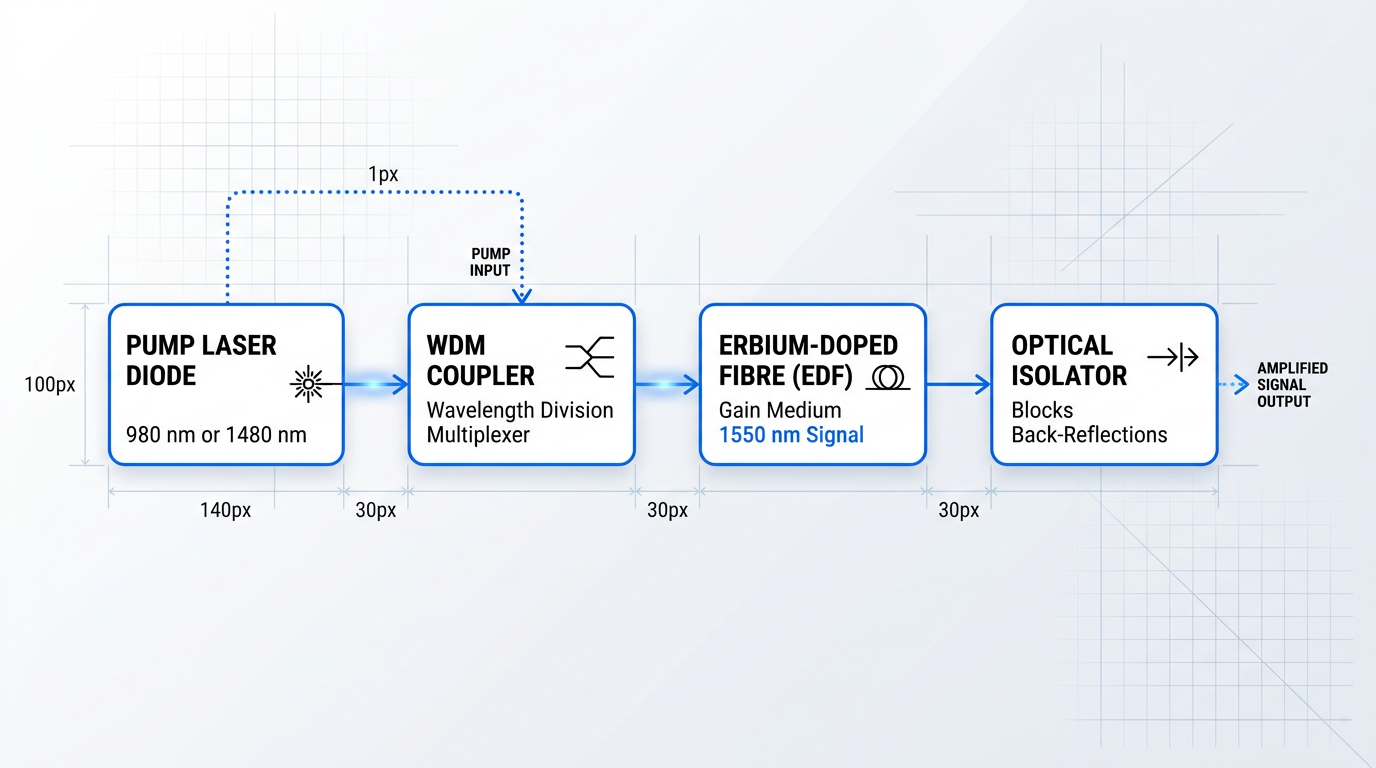
An EDFA amplifies optical signals by passing them through a length of erbium-doped fibre (EDF), a silica glass fibre whose core has been doped with trivalent erbium ions.
A pump laser — operating at either 980 nm or 1480 nm — excites those erbium ions into a higher energy state; when a signal photon in the 1550 nm telecommunications band passes through, it triggers stimulated emission, releasing an identical photon and amplifying the signal.
Four components make this work together as a practical device.
- Erbium-doped fibre: The gain medium. Erbium ions hosted in the silica core provide the population inversion needed for stimulated emission and signal amplification.
- Pump laser diode: Supplies the optical energy at 980 nm or 1480 nm that excites erbium ions into their upper energy state, enabling gain.
- WDM coupler: A wavelength-division multiplexer that combines the pump and signal wavelengths into a single fibre path entering the EDF.
- Optical isolator: Placed at the output to block back-reflections, preventing them from destabilising the amplifier or degrading noise performance.
This architecture is mature, compact, and manufacturable at scale — which is precisely why it has attracted serious attention for space laser communications.
Why EDFAs Are Used in Space
EDFAs offer a combination of properties that are difficult to match with alternative amplifier technologies: high gain, polarisation insensitivity, low noise, and low inter-channel crosstalk.
Equally important for space programmes is the technology's heritage — EDFAs are built from telecom-derived components with an established industrial supply base, which reduces development cost and qualification risk compared to purpose-built space photonics.
The growing deployment of optical inter-satellite links in LEO constellations and deep space relay architectures is translating that appeal into active procurement demand for EDFAs qualified to operate across a full mission lifetime in orbit.
What Radiation Hardening Means for an EDFA
In this context, radiation hardening means engineering the EDFA — principally the erbium-doped fibre and the surrounding system architecture — to maintain acceptable gain and noise figure performance across the full mission lifetime under the ionising radiation dose expected in the target orbit or trajectory.
The goal is not immunity to radiation; no passive optical component achieves that in a meaningful space radiation environment. The goal is controlled, predictable degradation within a performance envelope defined at mission design time — so that the link budget remains closed from launch through end of life.
A radiation hardened EDFA uses the same four functional building blocks as a standard device; the difference lies entirely in fibre material composition, co-doping chemistry, and system-level design choices that govern how the amplifier responds when ionising radiation begins accumulating in the glass.
The Core Tension: Why Hardening Is Non-Trivial
To create a viable gain medium, erbium ions must be incorporated into silica glass at concentrations high enough to produce useful amplification — but erbium has very low solubility in pure silica and tends to cluster at elevated concentrations, which quenches the gain.
The solution is to add co-dopants — most commonly aluminium, phosphorus, or germanium — which increase erbium solubility, suppress ion clustering, and shape the amplifier's gain spectrum.
Those same co-dopants are, unfortunately, the primary sources of radiation sensitivity in the fibre: they introduce structural sites in the glass matrix that, under ionising radiation, become light-absorbing defects known as colour centres, producing radiation-induced attenuation that robs the amplifier of gain.
The co-dopants that make an EDFA perform well are the same co-dopants that make it radiation-sensitive — you cannot simply remove them without degrading the amplifier.
This is not a problem that yields to a straightforward fix: stripping out the co-dopants to reduce radiation sensitivity also degrades gain performance, bandwidth, and noise figure, undermining the reasons for using an EDFA in the first place.
With that tension established, the next step is to examine what ionising radiation actually does to a fielded EDFA — the observable degradation in gain and noise figure that a system engineer would see at the link budget level, before the underlying material physics is examined.
Radiation-Induced Attenuation: The Measurable Cost
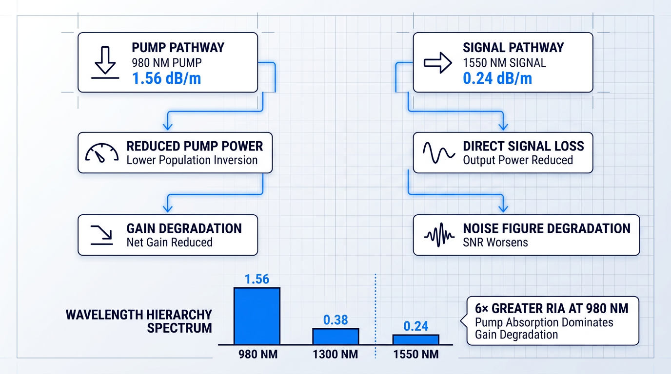
When ionising radiation strikes an EDFA, the damage is not random or vague — it manifests as a precise, measurable increase in optical loss called radiation-induced attenuation (RIA), and it attacks the amplifier through two simultaneous pathways: one that starves the gain medium of pump power, and one that directly absorbs the amplified signal.
RIA is defined as the increase in optical loss in a fibre caused by ionising radiation exposure, expressed in dB/m or dB/km at a specific wavelength. It is not a single number that characterises a fibre — it is a wavelength-dependent spectrum, and that wavelength dependence is central to understanding how radiation degrades an EDFA.
As the NASA GSFC Photonics Group summarises in its fibre radiation testing programme, RIA is dependent on dose rate, total dose, wavelength, and temperature — four independent variables, any of which can shift the measured result significantly.
Two Pathways: How RIA Erodes Gain and Noise Figure
RIA degrades EDFA performance through two distinct mechanisms that operate simultaneously, each attacking a different part of the amplification process.
- Pump pathway absorption: Increased loss at the pump wavelength (980 nm or 1480 nm) reduces the power reaching the erbium gain medium, lowering population inversion efficiency and cutting available gain.
- Signal pathway absorption: Increased loss at the signal wavelength (~1550 nm) directly attenuates the amplified output as it propagates through the irradiated gain fibre.
Both pathways reduce net gain. Both also degrade noise figure: a less efficiently inverted gain medium produces more amplified spontaneous emission (ASE) relative to the signal, worsening the signal-to-noise ratio at the amplifier output.
A NASA GSFC survey of erbium-doped fibre radiation effects describes this directly: radiation exposure induces colour centres that decrease small-signal gain by absorbing the pump signal, while the amplified signal is simultaneously absorbed, reducing output power.
Wavelength Dependence and Its EDFA Consequences
RIA is not uniform across wavelengths. The general trend, well established across fibre types and radiation sources, is that shorter wavelengths suffer greater radiation-induced absorption than longer wavelengths.
For an EDFA, this has a specific and important consequence: the 980 nm pump wavelength is substantially more susceptible to RIA than the 1550 nm signal wavelength.
Extrapolated data for a commercial erbium-doped fibre (HE980) at low dose rates illustrates the scale of this hierarchy clearly: at 200 krad total dose, the radiation-induced attenuation at 980 nm is approximately 1.56 dB/m, compared to roughly 0.38 dB/m at 1300 nm and 0.24 dB/m at 1550 nm — a factor of more than six between the pump and signal wavelengths.
This means pump absorption is the primary driver of gain degradation in most irradiated EDFA configurations, not a secondary concern. The pump wavelength selection decision — 980 nm versus 1480 nm — therefore carries direct radiation-performance implications, which later sections will develop.
Scale of the Problem: Fibre Composition Matters Enormously
The magnitude of RIA at 1550 nm varies by orders of magnitude depending on fibre composition, and this contrast is the single most important fact for understanding why fibre material selection is the primary lever in radiation-hardened EDFA design.
| Fibre Grade / Type | RIA at 1550 nm (1 MGy TID) | Notes |
|---|---|---|
| Radiation-hardened grade (pure silica core or F-doped) | <40 dB/km | Lowest RIA class; suitable for space optical systems |
| Radiation-tolerant grade (germanosilicate) | ~200 dB/km | Moderate sensitivity; higher RIA than PSC fibres |
| Radiation-sensitive grade (P-doped or Al-doped core) | >50,000 dB/km | Extreme sensitivity; used as dosimeters, not signal fibres |
Comparison of RIA at 1550 nm across fibre grade categories at 1 MGy total ionising dose, illustrating the orders-of-magnitude difference in radiation response between fibre types.
The contrast is stark: at the same total dose of 1 MGy, a phosphorus- or aluminium-doped fibre can exhibit RIA more than three orders of magnitude higher than a pure silica core fibre at 1550 nm.
Even at doses representative of typical space mission lifetimes, the separation remains dramatic. Pure silica core fibres achieve approximately 1 dB/km at 1550 nm for a total dose of 1000 Gy — a level that can be managed within a well-designed amplifier budget. Fibres doped with phosphorus or aluminium, by contrast, reach 10³ to 10⁴ dB/km at comparable doses, making them functionally unusable as gain media in any radiation environment.
This is why P-doped and Al-doped fibres, despite their advantages in terrestrial EDFA manufacturing, are exploited as radiation dosimeters in nuclear facilities rather than as candidates for space-qualified amplifiers.
Active vs Passive RIA Measurement: A Critical Distinction
Not all published RIA figures are equivalent, and engineers evaluating vendor radiation data need to understand a fundamental methodological distinction: whether a test was conducted under passive (unpumped) or active (pumped, operating) conditions.
Experimental comparisons of passive and active loss measurements in erbium-doped fibres show that active MOPA losses are consistently lower and recover more rapidly than passive losses measured at the same wavelengths.
The reason is that optical pumping causes concurrent partial recovery of radiation-induced defects — a process whose mechanism is covered in the next section on photobleaching. The practical consequence here is straightforward: passive fibre loss measurements will overestimate the RIA that an operating EDFA actually experiences, sometimes by a substantial margin.
NASA GSFC's fibre radiation testing programme explicitly flags this: fibres anneal very quickly after radiation exposure, meaning that measurements taken after irradiation rather than in-situ will underestimate RIA, while passive measurements taken without optical power will overestimate degradation in an active amplifier.
When reviewing radiation test data, the key question is always whether the measurement was in-situ and whether optical power was present — two conditions that can each shift the reported RIA figure significantly.
For the same total accumulated dose, a higher dose rate produces more RIA than a lower one. Laboratory irradiation tests necessarily run at dose rates many orders of magnitude above the actual space environment — meaning accelerated ground test data will systematically overestimate the RIA an EDFA accumulates in orbit. A dose rate reduction of 2 to 3 orders of magnitude can reduce radiation-induced effects by approximately one order of magnitude.
The dose-rate dependence of RIA has been confirmed across erbium-, ytterbium-, and co-doped fibre systems: for the same total dose, fibres irradiated at higher dose rates consistently exhibit greater photodarkening than those irradiated at lower rates, with differences on the order of 3–10% across the observed spectrum even for moderate dose-rate variations.
This matters directly for how ground test data should be read: an accelerated Co-60 test result is a conservative upper bound on in-orbit RIA, not a direct prediction of it — and the degree of conservatism scales with the ratio between test dose rate and mission dose rate.
With the observable consequences of radiation exposure now established — measurable RIA, dual-pathway gain degradation, wavelength-dependent severity, and the nuances of how that RIA is measured — the natural next question is why irradiated glass absorbs more light in the first place. That answer lies in the physics of colour centre formation, which the following section addresses.
Colour Centre Formation: Why Co-Dopants Are the Problem
The chemicals that make erbium-doped fibre work are the same chemicals that make it vulnerable to radiation. Co-dopants such as aluminium and phosphorus are chemically necessary to host erbium ions at useful concentrations in silica glass — but under ionising radiation, those same dopant sites become the primary sources of light-absorbing point defects that produce the RIA described in the previous section. This is the central tension in EDF design for space.
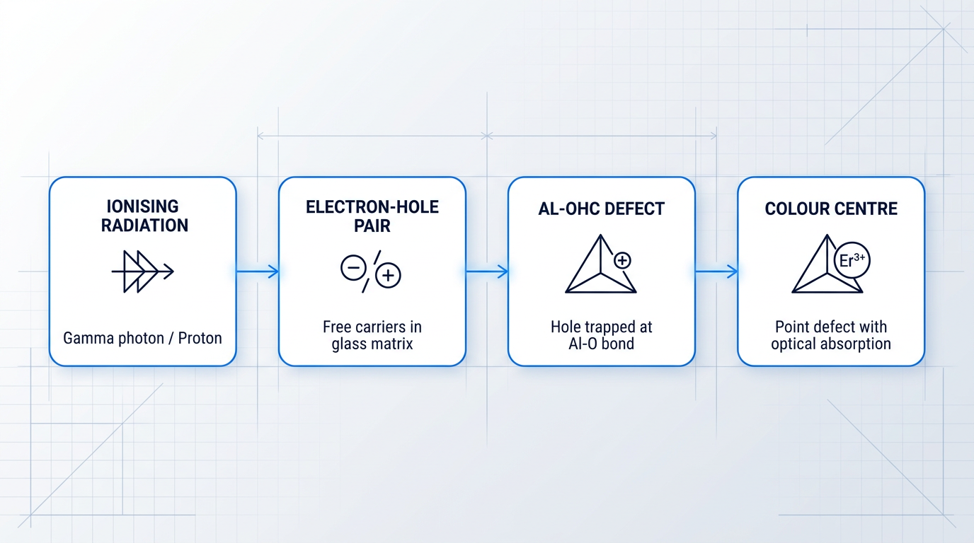
The root mechanism begins with energy deposition. When ionising radiation — gamma photons, protons, electrons — passes through the silica glass matrix, it excites electrons and generates electron-hole pairs throughout the material.
These free carriers migrate through the glass network until they encounter structural defect sites, where they become trapped. A trapped carrier at a defect site forms a colour centre: a point defect with a characteristic optical absorption band.
Colour centres in silica absorb light across a broad spectral range, with absorption tails that extend into the near-infrared — directly overlapping the pump band (~980 nm) and signal band (~1550 nm) relevant to EDFA operation. This is the microscopic origin of the RIA that degrades gain.
Pure silica glass, on its own, forms relatively few of these defects under radiation. RIA in pure-silica-core fibre is approximately 1 dB/km at 1550 nm for a total dose of 1000 Gy — a modest penalty that many systems can tolerate.
The problem is that pure silica cannot host erbium ions at the concentrations needed for practical amplification. In the absence of co-dopants, erbium ions aggregate into clusters, and concentration quenching through ion-ion energy transfer depopulates the upper laser level without producing stimulated emission, destroying gain efficiency.
Co-dopants solve this by modifying the local glass network around each erbium ion, increasing rare-earth solubility and spacing ions far enough apart to suppress quenching. Aluminium, for instance, forms [AlO₄]⁻ tetrahedral units in the silica network that create solvation shells around erbium ions, promoting dispersion and inhibiting clustering. Phosphorus similarly bonds preferentially with Er³⁺ ions, forming structured cages that prevent aggregation.
But those same structural modifications — the very sites that stabilise erbium in the glass — are preferentially susceptible to radiation-induced defect formation. The result is that fibres doped with aluminium or phosphorus exhibit RIA values of 10³ to 10⁴ dB/km at 1550 nm for a 1000 Gy dose: three to four orders of magnitude higher than pure silica.
Aluminium Oxygen Hole Centres (Al-OHC)
Aluminium is the most widely used co-dopant in erbium-doped fibres, valued for the broad, smooth gain spectra it produces. Under radiation, however, aluminium introduces the dominant class of absorbing defects in Al-co-doped glass: aluminium oxygen hole centres (Al-OHC).
An Al-OHC forms when a radiation-generated hole becomes trapped at an aluminium-associated site in the glass network — specifically at the oxygen atoms bonded to the [AlO₄]⁻ tetrahedra that aluminium substitutes into the silica lattice. The excess negative charge of these units makes them energetically favourable sites for hole capture, which is precisely why aluminium-doped glass is so susceptible.
Spectroscopic analysis of LEO-irradiated Er-doped fibres confirms that Al-related colour centres dominate the induced absorbance spectrum, with a characteristic absorption feature at approximately 2.2 eV (~560 nm) and an associated Al-OHC band near 3.1 eV (~400 nm), alongside contributions from intrinsic defects such as non-bridging oxygen hole centres (NBOHC).
Critically, the Al-OHC absorption is not confined to the visible. Its spectral tail extends into the near-infrared, contributing to loss at both the ~980 nm pump wavelength and the ~1550 nm signal wavelength — attacking EDFA performance through both the gain medium excitation and the signal channel simultaneously.
Phosphorus-Related Defects: P1 and P-OHC
Phosphorus co-doping introduces a distinct and particularly damaging class of radiation-induced defects. Two primary centres form under ionising radiation in phosphosilicate glass: the P1 defect (an electron-trap centre) and the phosphorus oxygen hole centre (P-OHC), where a hole is trapped on non-bridging oxygen atoms bonded to a phosphorus atom.
What makes phosphorus-related defects especially problematic for spaceborne amplifiers is their absorption location. The P1 centre absorbs at approximately 0.8 eV (~1600 nm) — placing it directly at the edge of and overlapping with the 1550 nm signal band, where absorption translates immediately into gain loss.
This signal-band absorption is the reason phosphorus-co-doped fibres are considered more detrimental for space applications than aluminium-co-doped fibres, despite aluminium's higher overall RIA magnitude: the P1 defect attacks the signal wavelength specifically, whereas aluminium-related centres affect a broader spectral range with comparatively less energy at 1550 nm.
Phosphosilicate fibres are common in Er/Yb co-doped fibre (EYDF) designs used for high-power amplification, where phosphorus is chosen to improve slope efficiency and promote energy transfer from Yb³⁺ to Er³⁺. Published results report a 30% gain degradation in EYDF amplifiers at a total dose of just 400 Gy — a consequence of this P1 and P-OHC vulnerability.
The P-OHC visible absorption band (centred near 500–505 nm in phosphate glass systems) also contributes to the overall induced loss profile, though the P1 centre's near-infrared absorption at ~1600 nm is the primary concern for signal-band operation.
Ion Clustering and Radiation Interaction
Even before radiation is considered, erbium ion clustering is a fundamental efficiency limit. When inter-ion separation falls below a critical threshold, excited-state energy transfer processes — particularly upconversion and pair-induced quenching (PIQ) — transfer energy between neighbouring ions rather than to the signal photon field.
This depopulates the upper laser level (the ⁴I₁₃/₂ manifold) without producing stimulated emission, reducing the population inversion available for gain. Conventional EDFAs are typically limited to erbium concentrations of approximately 0.1 wt% (~1 × 10¹⁹ ions/cm³) or below to keep PIQ effects manageable.
Radiation exposure can compound clustering effects by altering the local glass structure around erbium ions, potentially reducing the efficiency of energy transfer from the pump-excited manifold into the erbium gain transition and further degrading effective population inversion.
In erbium-doped fibres, it is the type and concentration of co-dopants — aluminium, phosphorus, germanium — that dominate radiation response, not the erbium concentration itself. The exact concentrations of rare-earth dopants only slightly affect radiation sensitivity, while the presence of dopants such as Al and P vastly increases induced loss. This makes co-dopant selection the primary lever for radiation hardening at the fibre level.
Understanding that radiation damage in EDF is fundamentally a co-dopant chemistry problem reframes the engineering challenge: the question is not how much erbium to use, but which co-dopants to choose and at what concentration — and whether their defect-forming tendency can be suppressed.
What the physics also reveals is that not all colour centres are equally stable. Some of the trap states that form under radiation can be depopulated by optical energy — a phenomenon that opens the door to partial recovery of transmission loss, which is the subject of the next section.
Photobleaching: How Optical Pumping Partially Reverses Radiation Damage
The colour centres established in the previous section are not all permanent fixtures. Some of the trap states created during irradiation are thermodynamically unstable, and optical energy can drive their depopulation — partially undoing the damage that radiation has done.
Photobleaching is the partial recovery of radiation-induced attenuation (RIA) that occurs when optical power is present in the fibre. It is an optically driven process — distinct from thermal annealing, which requires elevated temperatures to release trapped carriers — and it operates continuously whenever the fibre is illuminated.
The mechanism connects directly to the trap state physics described earlier. Colour centres formed during irradiation occupy energy levels within the silica glass matrix; photons at 980 nm pump wavelengths and at 1550 nm signal wavelengths both carry sufficient energy to excite trapped carriers out of a fraction of these states, reducing the absorbing defect population and thereby lowering RIA.
Research into actively pumped erbium-doped fibre amplifiers confirms that photobleaching produces measurable gain recovery during and after irradiation. The SPIE gamma radiation comparison study noted that gain was observed to increase during stabilisation periods with pumping present, explicitly attributing this to the photobleaching effect. Separately, the SPIE space-qualification work on 10 W PM amplifiers identified the ability to recuperate radiation-induced gain loss through photobleaching — pumping active fibres at nominal power for a period after irradiation — as the major practical result of their test programme.
Critically, this recovery is not linear with optical power. Research on the power dependence of photobleaching found that whilst fibres carrying light at 1050 nm showed large reductions in RIA compared to an unilluminated control fibre, the reduction was not proportional to power and saturates at higher powers — a result described as consistent with the theoretical models. Engineers cannot simply increase pump power indefinitely to recover gain; there is a threshold beyond which additional pump power yields diminishing returns.
For fibres with optimised core structures, the recovery achievable through photo-annealing can be substantial. A commercial radiation-tolerant erbium fibre, designed to exploit photoannealing from standard 980 nm pumping via a unique trivalent core matrix structure, demonstrated effective photoannealing recovery of up to 100% of RIA through excitation of the defects — illustrating the upper bound of what is achievable when fibre design is specifically engineered around this recovery mechanism.
For standard and commercial fibres, the practical implication is more modest but still meaningful. An EDFA that has experienced a radiation event — such as a transit through a high-flux region — may recover a significant fraction of lost gain once nominal pumping resumes, and this recovery trajectory should be factored into mission performance models rather than treated as a permanent worst-case loss.
Photobleaching also carries a consequential nuance for how ground-based qualification test results should be read. The dose-rate dependence observed consistently in rare-earth-doped fibre studies shows that higher ionising dose rates lead to more induced loss than lower dose rates for the same total accumulated dose. Since ground tests using Co-60 sources typically run at accelerated dose rates to reach the required total ionising dose in a manageable timeframe, the steady-state RIA measured during such a test will tend to be higher than what the same fibre would exhibit in orbit under the much lower, chronic dose rates of the actual space environment.
Because higher dose rates produce more induced loss than lower dose rates at equivalent total doses (a consistent finding across rare-earth-doped fibre studies), Co-60 qualification tests run at accelerated rates can overestimate the RIA a fibre will actually experience in orbit. This is a nuance in test interpretation, not an invalidation of ground testing — but it underscores why irradiation testing conducted with representative optical power present in the fibre provides more mission-representative performance data than passive testing alone.
With an understanding of photobleaching established — that optical pumping continuously and partially counteracts colour centre formation, that this recovery saturates with power, and that it is dose-rate-dependent — the next question is what this means for how an EDFA is operated during its mission. Whether the amplifier is powered ON or OFF during radiation exposure turns out to be a first-class design parameter, not a secondary consideration, and that is the focus of the next section.
How Operating Mode Defines End-of-Life Gain
Two EDFAs receive identical total ionising doses over the same mission duration. One was actively pumped throughout; the other spent critical phases in standby. At end of life, their gain performance diverges significantly — not because of any difference in the radiation environment, but because of a single design decision: whether the amplifier was powered ON or powered OFF during irradiation. This is one of the most consequential and least-discussed variables in spaceborne EDFA performance, and it deserves to be treated as a first-class design parameter.
The reason operating mode matters so much comes directly from the physics established in the preceding sections. Colour centres form continuously under irradiation. Photobleaching — driven by the optical field of the pump — continuously depopulates a fraction of those trap states. When the EDFA is powered, both processes run simultaneously, and they compete.
The Powered-ON Advantage: A Dynamic Steady State
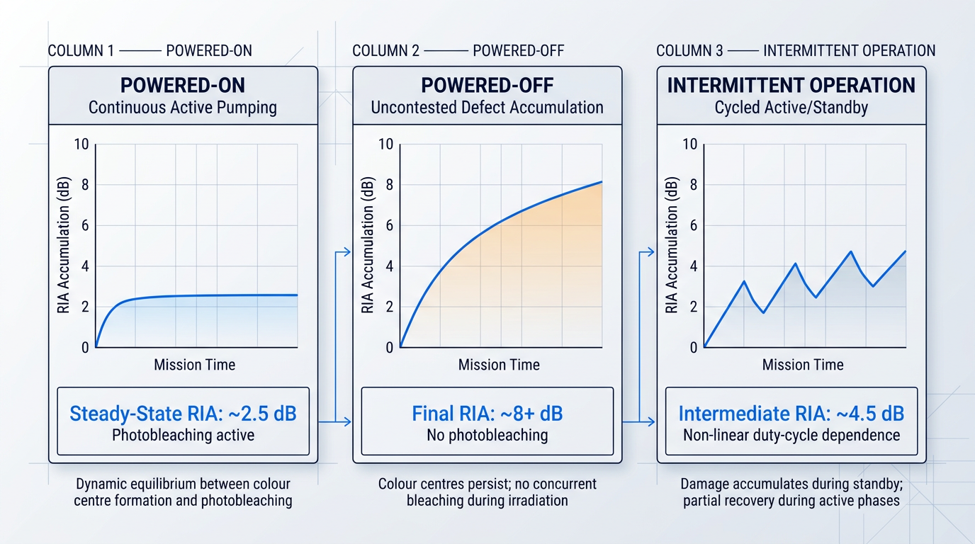
Under continuous active pumping, the gain fibre reaches a dynamic steady state in which the rate of colour centre formation is partially offset by the rate of photobleaching-driven depopulation.
The practical result is that the steady-state RIA accumulated by a continuously pumped fibre is substantially lower than the RIA that accumulates in an unpowered fibre receiving the same total dose.
Experimental data from gamma irradiation testing confirms this directional relationship. In studies comparing active and passive irradiation of erbium-doped fibres, passive (unpowered) EDF-PM fibres lost more than 8 dB of gain during irradiation, while actively pumped fibres operating at nominal power showed markedly lower gain loss under equivalent dose conditions — with photobleaching identified as the primary mitigating mechanism.
Critically, this is not simply a post-irradiation recovery effect: the photobleaching occurs during irradiation, suppressing the peak damage level rather than merely accelerating recovery afterwards.
The Powered-OFF Risk: Uncontested Defect Accumulation
An unpowered fibre accumulates colour centres without any concurrent bleaching. Every trap state that forms persists until the device is eventually switched on — at which point photobleaching begins, but from a much higher damage baseline.
The recovery that follows power-on is real but limited. As established in the preceding section, photobleaching provides only partial recovery: the recoverable fraction depends on the specific colour centre species present and their thermal stability, and some trap populations are effectively permanent on mission timescales.
The implication for mission planning is direct. A device left powered OFF through a high-dose-rate phase — such as Van Allen belt transit for beyond-LEO missions — may accumulate a damage level from which it cannot recover to within acceptable gain margins, even after extended photobleaching once on-orbit operations begin.
Space qualification testing has confirmed that photobleaching after irradiation can recuperate a meaningful portion of gain loss, with many commercial fibres achieving post-bleaching losses below 3 dB — but this figure represents the ceiling of recovery, not a guaranteed outcome, and it is substantially better than the 8+ dB loss seen in passively irradiated fibres before any recovery is applied.
Intermittent Operation: The Real-World Scenario
Most missions do not operate EDFAs at 100% duty cycle, nor do they keep them fully powered off throughout radiation exposure. The realistic scenario is intermittent operation: the amplifier cycles between active and standby modes according to mission scheduling, power budgets, and link demand.
During standby intervals, colour centres accumulate unimpeded. During active intervals, photobleaching partially clears them. The net damage level at any point in the mission reflects the cumulative history of this cycling — and the relationship is non-linear.
A device operated at 50% duty cycle does not accumulate 50% of the radiation damage of a fully powered-OFF device. The kinetics of colour centre formation and photobleaching-driven annealing interact in ways that make the damage-vs-duty-cycle relationship fundamentally non-linear — and that non-linearity must be modelled explicitly, not interpolated.
Experimental work within the ESA-funded EDURAC programme, conducted by Menlo Systems and iXblue, directly demonstrated this duty-cycle dependence. Fibres irradiated at 90% duty cycle showed meaningfully different RIA accumulation profiles compared to fibres irradiated at 10% duty cycle under the same total dose — confirming that operating duty cycle is a measurable driver of end-of-life performance, not merely a theoretical variable.
The EDURAC results also confirmed a directional principle: fibres age more slowly when operated at higher duty cycles, because more continuous pumping sustains a higher rate of concurrent photobleaching relative to defect formation.
Mission Planning: Specifying Operating Mode as a Design Parameter
The practical consequence of this physics is that the operating state of the EDFA during each mission phase should appear explicitly in the system specification — not be left as an undocumented consequence of power management decisions made elsewhere in the spacecraft design.
- Launch phase: Typically powered off for safety and vibration reasons, but radiation dose during launch ascent is generally low — this phase is not the primary concern.
- Van Allen belt transit: The highest dose-rate phase for GEO transfer and deep-space missions. Keeping the EDFA powered during transit can substantially limit damage accumulation.
- On-orbit operations: Duty cycle during normal operations sets the long-term steady-state RIA level. Higher duty cycle correlates with lower accumulated damage at end of life.
Engineers and mission planners who explicitly specify that the EDFA should remain powered ON during high-radiation-flux phases — and who design the power budget to accommodate this — can carry a meaningful performance advantage into end-of-life gain margin calculations.
This is not a minor optimisation. For missions transiting the Van Allen belts, the difference between a powered and unpowered amplifier during that phase can represent the difference between an amplifier that recovers to within gain specification and one that does not.
The Modelling Challenge: Static Test Data Is Not Enough
Predicting end-of-life gain for a duty-cycled mission profile is genuinely difficult, and current qualification practice has a structural gap here.
Published irradiation test datasets are almost universally collected under static conditions: either fully powered ON or fully powered OFF throughout the test. These datasets characterise the two performance extremes well, but they do not directly describe the intermediate damage trajectories that real duty-cycled missions will follow.
Bridging this gap requires nth-order kinetic models of colour centre formation and thermally-driven annealing — models of the type developed by Friebele and Griscom and extended by subsequent researchers — that can account for the time-varying interplay between irradiation and bleaching across a realistic mission timeline.
Williams, Putnam, and Friebele demonstrated that radiation-induced loss growth follows a power law of dose, and that recovery can be described by a sum of exponential decay terms — but also that simple colour centre models overestimate dose-rate effects, which underscores why extrapolating static test data to intermittent scenarios requires explicit modelling rather than linear scaling.
The takeaway for procurement and qualification teams is not that prediction is impossible, but that it requires deliberate modelling effort. Extrapolating a powered-OFF test result to a 60% duty-cycle mission profile by simple interpolation will produce an inaccurate end-of-life estimate — potentially an optimistic one, depending on the kinetics of the specific fibre composition.
Operating mode is a powerful lever, but it operates on top of whatever baseline radiation sensitivity the gain fibre possesses by virtue of its material composition and co-doping chemistry. A fibre with poor intrinsic radiation hardness will still accumulate substantial damage even under continuous pumping. That baseline is what the fibre design strategies covered in the next section address.
Fibre Design Strategies for Radiation Hardening
The preceding sections established that co-dopants — not erbium itself — are the primary architects of radiation damage in an EDFA gain medium. That diagnosis points directly toward the design response: if the dominant damage pathway runs through specific dopant chemistries, then the fibre composition is the first and most fundamental lever available to the engineer. Every strategy discussed here is an attempt to either eliminate the radiation-sensitive trap states from the glass matrix, or intercept the radiation-generated charge carriers before they can form the absorbing colour centres that degrade gain.
The challenge is that fibre composition cannot be freely optimised for radiation tolerance alone. Waveguide physics, erbium solubility, amplifier efficiency, and manufacturing constraints all impose competing demands. The strategies below each represent a specific trade-off within that co-optimisation space.
Pure Silica Core: Removing the Damage Source
The most direct response to the co-dopant problem is to remove co-dopants from the core entirely. Pure silica core fibres achieve this, and the radiation performance improvement is dramatic: RIA at 1550 nm is approximately 1 dB/km at a total dose of 1000 Gy — orders of magnitude lower than fibres doped with phosphorus or aluminium, which exhibit RIA in the range of 10³ to 10⁴ dB/km under equivalent conditions.
The reason for this improvement maps directly onto the colour centre physics established earlier. Without aluminium or phosphorus in the core, the Al-OHC and P-OHC hole centres that absorb strongly around 1550 nm simply cannot form in significant numbers. The dominant damage pathway is eliminated at its source.
The engineering difficulty is that standard single-mode fibres require a refractive index contrast between core and cladding to achieve waveguiding — and conventional designs achieve this by raising the core index with germanium, aluminium, or phosphorus. Removing these index-raising co-dopants from the core is therefore not a trivial substitution. Erbium must still be incorporated into the core for amplification, and achieving adequate erbium solubility in a pure silica host without radiation-sensitive co-dopants requires careful preform chemistry and manufacturing process control.
Fluorine-Doped Cladding: The Enabling Complement
Pure silica core fibres become practically realisable through a complementary approach to the waveguide index problem: rather than raising the core index, fluorine doping of the cladding lowers the cladding index instead. The necessary refractive index contrast is achieved without introducing any radiation-sensitive dopants into the core region where the guided optical mode is concentrated.
Fluorine-doped double-clad fibre is a well-established technology, widely used in high-power amplifier designs. Its role in radiation-tolerant fibre is the same in principle: it is the structural enabler that makes pure silica core geometry practical. Because the fluorine resides in the cladding rather than the core, it does not contribute to the colour centre population that matters for signal and pump attenuation at 1550 nm and 980 nm respectively.
The two approaches — pure silica core and fluorine-doped cladding — are not alternatives. They work together as a system, with fluorine-doped cladding providing the waveguide confinement that pure silica core fibres require.
Cerium Co-Doping: Intercepting Radiation-Generated Holes
Not all fibre systems can move to pure silica core architectures. High-efficiency erbium-ytterbium (Er/Yb) fibres typically require phosphorus co-doping to achieve adequate slope efficiency, and phosphorus is one of the most radiation-sensitive dopants in the silica system. For these fibre compositions, a different mitigation strategy is needed: one that suppresses colour centre formation without removing the necessary co-dopants.
Cerium co-doping addresses this at the charge carrier level. When ionising radiation generates electron-hole pairs in the glass matrix, cerium ions (Ce³⁺/Ce⁴⁺) act as competitive hole traps — they preferentially capture the radiation-generated holes before those holes can migrate to phosphorus sites and form the P-OHC colour centres described earlier. The cerium-related defects that do form do not absorb significantly at 1550 nm, so the interception is spectrally benign.
The consequences of unmitigated phosphorus-induced damage are substantial. Reported data for phosphorus-doped EYDF without cerium shows gain degradation of approximately 30% at a total dose of 400 Gy — a level of degradation that materially affects amplifier lifetime in space applications. Cerium co-doping mitigates this by trapping the hole defects responsible for P-OHC formation before they accumulate.
The limitations of this approach are significant and must be understood before treating cerium as a straightforward upgrade. Cerium is a targeted solution specifically for phosphosilicate systems where P-OHC formation dominates the damage response. It requires careful optimisation of the cerium concentration relative to the erbium, ytterbium, and phosphorus concentrations: insufficient cerium leaves the hole trapping incomplete, while excessive cerium can quench erbium emission through energy transfer mechanisms that reduce amplifier efficiency.
Cerium co-doping also complements photobleaching as a concurrent mitigation mechanism. Both act to limit colour centre accumulation during active operation, but through distinct pathways: cerium reduces the rate at which absorbing centres form, while photobleaching drives their partial destruction once formed.
Germanium Co-Doping: Spectral Selectivity as a Hardening Mechanism
The assumption that any dopant-induced radiation defect is harmful to EDFA performance deserves scrutiny. The relevant question is not whether a dopant creates defects under irradiation, but where those defects absorb. Germanium co-doping illustrates this distinction clearly.
When ionising radiation strikes a germanium-doped fibre, it induces hole-trapping defects including Ge(2) and Ge(3) centres. Critically, these defects absorb primarily in the ultraviolet-to-visible spectral range, not at 1550 nm or 980 nm. The signal and pump wavelengths that govern EDFA performance therefore pass through the germanium-doped glass with comparatively little additional loss, even as the germanium-related defect population grows under accumulated dose.
Recent experimental work comparing cerium and germanium co-doping in Er/Yb fibres has shown that large concentrations of germanium can significantly improve radiation hardness at 1550 nm, with germanium-doped EYDF matching cerium-doped EYDF amplification performance to within 10% — and in certain compositions outperforming cerium in terms of RIA mitigation around 1550 nm without measurably affecting optical performance.
This finding has practical implications for fibre design. Germanium has historically been used in fibre cores primarily as an index-raising co-dopant, and its radiation sensitivity at visible wavelengths was treated as a liability. The emerging picture is more nuanced: at the signal wavelengths that matter for space-borne optical amplifiers, germanium's radiation-induced absorption is weak, and its presence can actively suppress the formation of more damaging colour centres at 1550 nm.
A co-dopant that generates radiation-induced defects absorbing in the UV-visible range is far less damaging to a 1550 nm amplifier than one generating defects at the signal or pump wavelength. Germanium's defect spectrum makes it a spectrally selective hardening agent, not simply a radiation-sensitive impurity to be minimised.
Nanoparticle Doping: Decoupling the Rare-Earth Environment
In conventional solution-doped fibres, erbium ions are distributed through the bulk silica glass matrix, and their local chemical environment is determined by whatever co-dopants are present in the glass. This creates a fundamental tension: the co-dopants needed to solubilise erbium and suppress ion clustering are often the same co-dopants that generate radiation-sensitive colour centres.
Nanoparticle-doped fibres address this tension by incorporating rare-earth ions into discrete oxide nanoparticles embedded within the silica matrix rather than distributed through it. This architecture allows the local environment of the erbium ions to be controlled independently of the bulk glass composition: the nanoparticle chemistry can be optimised for erbium solubility and reduced ion clustering, while the surrounding silica matrix can be kept free of high concentrations of radiation-sensitive dopants.
The approach is under active investigation by the research community. Its potential advantage — decoupling rare-earth ion environment from bulk glass dopant chemistry — is mechanistically well-motivated, but the technique remains at the research stage rather than a mature commercial standard, and the design space for nanoparticle composition and size continues to be explored.
Hydrogen Loading: A Fundamental Wavelength Conflict
Hydrogen loading takes a different approach to radiation hardening: rather than modifying the dopant chemistry, it attempts to passivate the defect sites before radiation exposure occurs. H₂ molecules diffused into the glass matrix react with dangling bonds — unsatisfied silicon and oxygen bonds at structural defect sites — that would otherwise become radiation-induced absorbers under ionising exposure. By occupying these trap states before they can be activated by radiation, hydrogen loading reduces the available defect density.
The trade-off is fundamental and directly conflicts with the operating wavelength of EDFAs. Hydrogen incorporation into silica creates silanol (Si-OH) groups, which carry a strong absorption overtone at approximately 1.38 µm and an absorption tail that extends into the 1550 nm signal band. For an amplifier operating at 1550 nm, this OH-induced absorption competes directly with the signal, and can negate the gain benefit of reduced RIA.
Hydrogen loading is not a failed technique — it has genuine utility in fibre applications operating at other wavelengths, and it has been explored as a method for passivating non-bridging oxygen hole centres (NBOHCs) in radiation-tolerant passive fibres. For 1550 nm EDFA applications, however, the silanol absorption tail imposes a wavelength-compatibility constraint that limits its practical applicability as a hardening strategy for the gain fibre itself.
Taken together, these fibre-level strategies represent the foundational layer of radiation hardening for a radiation hardened EDFA: they determine the inherent sensitivity of the gain medium before any system-level choices are made. But fibre composition alone does not complete the picture. The next layer of mitigation — how the system architecture around the fibre is designed to manage accumulated damage through pump power, fibre length, and operational strategy — is the subject of the following section.
System-Level Mitigation: Pump Power and Architecture
Selecting a radiation-tolerant gain fibre is necessary — but it is only half the engineering problem. The system architecture surrounding that fibre determines how much of its residual radiation sensitivity actually manifests as end-of-life gain degradation. Fibre length, pump wavelength, pumping geometry, and redundancy strategy all interact with the fibre's material properties to set the performance floor a radiation hardened EDFA can hold across a multi-year mission.
Fibre Length vs Erbium Concentration: A Genuine Trade-Off
The intuitive response to radiation-induced attenuation (RIA) is to shorten the gain fibre: less active medium exposed to radiation means less total accumulated loss along the optical path.
The problem is that shortening the fibre while maintaining the same total gain requires a proportionally higher erbium doping concentration — and above a certain threshold, erbium ions begin to cluster.
Clustered ions degrade amplifier efficiency through concentration quenching and upconversion: instead of contributing to stimulated emission, excited ions transfer energy non-radiatively to neighbouring ions, dissipating it as heat rather than signal gain.
The optimum fibre length is therefore a balance between two competing failure modes: RIA accumulation, which worsens with increasing fibre length, and clustering-related efficiency loss, which worsens with increasing erbium concentration as fibre length is reduced.
This is a genuine design optimisation, not a rule of thumb — and the answer shifts depending on the target total dose, the specific fibre chemistry selected in §8, and the amplifier's gain requirement. A fibre with excellent intrinsic radiation tolerance can sustain a longer length before RIA accumulation becomes the dominant concern; a more radiation-sensitive fibre pushes the optimum toward shorter lengths despite the concentration penalty.
Pump Power Headroom and Dynamic Compensation
As radiation accumulates over a mission, colour centres absorb an increasing fraction of the pump power before it can drive population inversion in the erbium ions — the gain medium becomes progressively less efficient at converting pump photons into signal gain.
One well-established architectural response is to design the amplifier with deliberate pump power headroom at beginning-of-life: the pump diodes are capable of delivering more power than the amplifier needs at launch, so that power can be increased incrementally over the mission to compensate for growing pump absorption losses.
This strategy has been validated in space-qualified amplifier development programmes. ESA's STAR CuCo programme demonstrated that an oscillator whose output power decreased to 70% of its initial value under a 30 Gy (3 krad) radiation load could recover its target performance simply by increasing pump power — with no change to the optical spectrum or pulse characteristics.
The strategy has real limits, however. Pump diode output power is finite, and the diodes themselves degrade over mission lifetime through gradual output power reduction driven by thermal and electrical stress — even when derated.
This means the headroom margin must be sized to cover both the expected RIA-driven pump absorption increase and the anticipated pump diode degradation over the full mission duration — two degradation budgets that must be summed, not treated independently.
Pump Wavelength Selection: 980 nm vs 1480 nm
Under unirradiated conditions, 980 nm pumping is the preferred choice for most EDFA designs: it produces higher population inversion, lower noise figure, and better power conversion efficiency than 1480 nm pumping.
Radiation changes that calculus. Because colour centres absorb more strongly at shorter wavelengths, the 980 nm pump band is substantially more susceptible to RIA than the 1480 nm band.
| Wavelength | RIA Sensitivity (dB/m·krad) | Role in EDFA |
|---|---|---|
| 980 nm | ~0.013 | Primary pump wavelength |
| 1300 nm | ~0.004 | Intermediate reference |
| 1550 nm | ~0.0025 | Signal / 1480 nm pump band proxy |
Quantitative comparison of radiation-induced attenuation sensitivity at pump and signal wavelengths for erbium-doped fibre, from NASA GSFC data (Ott / Williams et al.)
The data shows an order-of-magnitude difference in radiation sensitivity between the 980 nm pump band and the 1550 nm signal band — and the 1480 nm pump wavelength sits close to that more-tolerant long-wavelength regime.
For a mission accumulating 100 krad total dose with several metres of gain fibre, the additional pump absorption at 980 nm can represent a substantial fraction of the available headroom budget — a loss that 1480 nm pumping would largely avoid.
The trade-off has no universal answer. 980 nm pumping is the right choice when end-of-life noise figure is tightly constrained and total dose is modest enough that pump absorption growth can be managed within the headroom margin. 1480 nm pumping becomes attractive for higher total dose missions or longer lifetimes where preserving pump efficiency matters more than achieving the lowest possible noise figure at beginning-of-life.
Bidirectional Pumping and Distributed Photobleaching
In a unidirectionally pumped amplifier, pump absorption is concentrated near the input end of the gain fibre, where pump intensity is highest — which means photobleaching activity is also concentrated there, leaving the distal portion of the fibre with weaker optical bleaching of radiation-induced colour centres.
Bidirectional pumping distributes the pump intensity more evenly along the full fibre length by injecting pump power from both ends simultaneously.
The radiation-tolerance benefit follows directly from the photobleaching physics established earlier in this guide: more uniform pump intensity means more uniform optical bleaching of colour centres along the entire gain medium, rather than a well-bleached input section followed by a progressively more damaged distal section.
This spatial distribution of photobleaching activity can meaningfully improve the effective radiation tolerance of a given fibre, without requiring any change to the fibre material itself — it is a system architecture choice that complements, rather than substitutes for, the material-level hardening strategies covered in the previous section.
Double-Clad Architectures for High-Power Applications
For inter-satellite link applications requiring output powers above approximately 1 W, cladding-pumped double-clad fibre architectures become necessary: the pump light propagates in the inner cladding rather than the core, allowing high-brightness multimode pump diodes to be used at power levels that core-pumped designs cannot reach.
The consequence is that pump intensity in the core is substantially diluted by the larger cladding cross-section, requiring higher erbium concentrations in the core to compensate — which reintroduces the clustering concern discussed under fibre length optimisation.
The same radiation-hardening strategies apply to double-clad designs, but the optimisation space is tighter: the concentration requirements are more demanding, the clustering threshold is easier to breach, and the pump headroom strategy must account for the inherently lower pump coupling efficiency of cladding-pumped geometries.
Redundancy, Derating, and Pump Multiplexing
Multiple pump laser diodes — combined through pump combiners and operated with cold-spare switching or derated drive currents — address two distinct but related problems: reliability against individual pump diode failure, and the operational flexibility needed to implement dynamic compensation.
Derating is particularly important. Space-qualified amplifier programmes have demonstrated that running pump diodes at a fraction of their rated output current — in some cases as low as one-quarter to one-third of maximum — substantially reduces thermal and electrical stress, with life-test data indicating no significant gradual degradation over mission-relevant durations when derated as planned.
In a cold-spare architecture, a failed primary pump diode is switched out and a previously unpowered spare is brought online — preserving the total available pump power without requiring the remaining active diodes to be driven harder.
Pump combiner reliability is a non-trivial engineering concern in multi-pump designs. SPIE evaluation programmes have found significant variation in combiner survival rates across suppliers under space environmental conditions, with temperature stress proving more destructive than vibration — underscoring that the combiner itself is a critical reliability element, not just a passive optical junction.
Pump multiplexing does not reduce RIA in the gain fibre itself — but it preserves the system's capacity to deliver adequate pump power throughout the mission, which is ultimately what determines whether the headroom strategy remains viable at end-of-life.
No single mitigation layer — not fibre material choice, not pump wavelength selection, not redundancy architecture — is sufficient on its own. End-of-life gain performance is determined by how well all these layers interact: a well-chosen fibre with poor pump management will still fail; a robust pump architecture cannot compensate for a fundamentally radiation-sensitive gain medium.
With both fibre-level and system-level mitigation strategies now in hand, the next step is understanding how different mission radiation environments translate these design choices into concrete specification requirements — and which strategies matter most for LEO, GEO, and deep space applications.
Mission Environments: LEO, GEO, and Deep Space
All of the mitigation strategies covered in the preceding sections — fibre length optimisation, pump power management, bidirectional pumping, cerium co-doping, pure-silica-core designs — are only meaningful once you know what radiation environment they must withstand. An EDFA designed for a 3-year LEO mission and one designed for a 15-year GEO communications satellite may use the same amplification physics, but they are fundamentally different engineering problems: different total ionising dose (TID) targets, different dominant radiation sources, and different qualification philosophies.
LEO: Moderate Doses, SAA Transients
In low Earth orbit, the dominant radiation sources are trapped protons and electrons in the inner Van Allen belts, with the South Atlantic Anomaly (SAA) acting as the primary dose contributor for most missions below 1,000 km altitude.
For a shielded component in a low-inclination LEO orbit at roughly 550 km, SPENVIS modelling with 2.54 mm aluminium shielding yields approximately 2.5 krad(Si)/year; a polar orbit at 800 km under the same shielding rises to approximately 5.6 krad(Si)/year, reflecting the greater time spent in high-latitude regions where the radiation belts dip lower. NASA guidance for low-inclination LEO missions consistently cites approximately 1–2 krad(Si)/year behind 100 mils (2.54 mm) of aluminium as a practical planning figure for shielded components.
From an EDFA specification standpoint, LEO's relatively moderate dose environment is the most accessible orbit for lightly radiation-tolerant gain fibres. More importantly, it is the environment where the powered-ON advantage discussed in the operating-mode section is most practically exploitable: continuous pump operation drives continuous photobleaching, which partially offsets accumulated colour centre formation over the mission lifetime.
The important nuance is that LEO is not simply a low-dose environment — it is a pulsed dose environment. Each SAA crossing delivers an intermittent dose-rate spike that can cause transient gain perturbations even when the total accumulated dose over the mission remains manageable, a distinction that matters for link-budget planning on optical communication payloads.
GEO: Higher Lifetime Doses, Longer Missions
Geostationary orbit sits outside the trapped radiation belts, so the dominant sources shift to galactic cosmic rays (GCRs) and solar particle events (SPEs). The character of the dose changes accordingly: instead of the pulsed, belt-dominated environment of LEO, GEO presents a steady GCR background punctuated by acute, unpredictable SPE events that can temporarily elevate dose rates by an order of magnitude.
Behind 2.54 mm aluminium shielding, SPENVIS modelling places GEO TID at approximately 259 krad(Si)/year — substantially higher than LEO. NASA guidance for a 7-year GEO mission cites approximately 50 krad(Si) assuming spacecraft shielding, while SPIE qualification work for GEO fibre-optic interrogation systems has reported expected TID in the range of 100–300 krad over a 15-year satellite lifetime.
The mission lifetime consequence is the critical driver: GEO communications satellites typically operate for 15 years. At a conservative shielded dose rate of 5–10 krad(Si)/year, the arithmetic is unambiguous — a GEO EDFA must be qualified to 75–150 krad(Si) before any radiation design margin is applied, and standard practice calls for a margin factor of at least 2, pushing the qualification target to 150–300 krad(Si).
This is where the fibre material choices discussed in the fibre design section become genuinely consequential. For a 3-year LEO mission, the difference in end-of-life gain between an aluminosilicate and a pure-silica-core fibre may be tolerable; for a 15-year GEO mission accumulating 150 krad(Si) or more, that same difference can determine whether the amplifier meets its link budget at end of life.
Deep Space and Interplanetary Missions
Beyond the magnetosphere, the trapped-belt contribution disappears entirely and galactic cosmic rays dominate continuously. The GCR environment is isotropic — arriving from all directions — energetic, and largely impossible to shield against completely, because the high particle energies mean that adding shielding mass beyond a practical threshold yields diminishing dose reduction.
The shielding sensitivity for deep space photonic devices is illustrated starkly by Mars mission data from NASA NTRS 20140002978: with 0.762 mm aluminium shielding, total mission dose for a Mars round trip is approximately 11.2 krad(Si); with no shielding at all, the same mission delivers approximately 253 krad(Si). The factor-of-22 difference between those two numbers is the engineering value of even minimal enclosure shielding for a deep space optical amplifier.
Any mission bound for deep space must also traverse the Van Allen belts on departure — a transit that contributes an acute dose on top of the steady-state GCR dose accumulated during cruise. The total dose from a direct Earth-to-Moon transfer behind 100 mils (2.54 mm) of aluminium is approximately 0.247 krad(Si), while a spiral low-thrust trajectory spending months in the belts can accumulate 177–545 krad(Si) behind the same shielding, depending on transit duration. For interplanetary missions, this Van Allen belt transit dose is front-loaded at the very start of mission life — before science operations begin.
The operating-mode decision during belt transit is therefore one of the most consequential early-mission design choices for a space EDFA. Specifying that the amplifier should be powered on — and therefore photobleaching — during the transit through the belts directly reduces the net accumulated damage at the point when dose rates are highest. This is a concrete, actionable design requirement that mission planners can write into the operational concept.
The data table below compares the three mission environments across the axes most relevant to EDFA specification.
| Parameter | LEO (low-inclination, ~550 km) | GEO (35,793 km) | Deep Space / Interplanetary |
|---|---|---|---|
| Dominant radiation sources | Trapped protons and electrons; SAA crossings dominate dose for low-inclination orbits | Galactic cosmic rays (GCRs); solar particle events (SPEs) | GCRs continuously; SPEs during solar events; trapped belts during Earth departure transit |
| Approx. TID rate (shielded, 2.54 mm Al) | ~2.5 krad(Si)/yr (550 km, 6° orbit); ~5.6 krad(Si)/yr (800 km polar) | ~259 krad(Si)/yr (SPENVIS); ~5–10 krad(Si)/yr behind heavier spacecraft shielding | ~10 rad(Si)/yr GCR-only in open space; 11.2 krad(Si) total for Mars mission (0.762 mm Al) |
| Typical mission duration | 3–7 years (commercial LEO constellations) | 15 years (GEO communications satellites) | 3–7 years (planetary missions) |
| EDFA qualification implication | Lightly radiation-tolerant fibres viable; powered-ON photobleaching offsets accumulated damage | High total dose (75–300 krad(Si) before margin) makes fibre material choice critical | Shielding strategy dominates; belt transit operating mode is a key early-mission design decision |
Comparison of LEO, GEO, and deep space radiation environments across the key axes that drive EDFA specification and qualification requirements.
The table reveals a pattern that goes beyond simple dose scaling: as orbit altitude and mission duration increase, not only does the cumulative TID requirement grow, but the character of the radiation environment changes in ways that affect which mitigation strategies are most effective. In LEO, the pulsed nature of SAA crossings means transient gain management matters alongside total dose hardness. In GEO, the steady GCR background and acute SPE risk require fibres that perform well under both chronic and acute exposure. In deep space, shielding decisions made at the spacecraft design stage — not component-level hardening alone — determine whether the EDFA survives the mission.
For any space EDFA, the mission radiation environment — derived from orbit, shielding configuration, and mission duration — is the correct starting point for qualification. A component datasheet showing radiation tolerance to a given level is only meaningful once you know whether that level actually covers your mission dose requirement. Generic figures are useful for early scoping; mission-specific modelling is required before any qualification programme begins.
NASA guidance published in NTRS 20140002978 provides practical starting points for translating environment into component-level test targets: 300 krad(Si) for unshielded external photonic devices on an interplanetary mission, and 15 krad(Si) for devices with at least 0.762 mm aluminium shielding (typically provided by the component package or enclosure). These figures are explicitly scoping values — the same document notes that mission-specific modelling using tools such as SPENVIS and SHIELDOSE-2 is the appropriate basis for deriving actual component requirements.
The correct engineering process is to model the specific orbit, shielding configuration, and mission duration using validated radiation transport codes, derive a component-level TID requirement, and then apply an appropriate radiation design margin — typically a factor of 2 or more — to account for environment variability and component-to-component spread. Picking a number from a table and treating it as a qualification target, without that mission-specific modelling step, is a common source of both over-specification and under-specification in photonic component procurement.
With the mission dose requirement established, the next question is how to test to it — which is where ground qualification programmes, accelerated dose-rate protocols, and the critical nuances of active versus passive irradiation become the focus. That is the subject of the following section on radiation qualification and testing.
Qualifying a Radiation-Hardened EDFA: Standards and Critical Nuances
Engineering radiation hardness into an EDFA is only half the problem. The other half — the half that separates a component that performs in orbit from one that merely looks credible on paper — is verification. And verification is harder than it sounds, because the test conditions used to generate qualification evidence can systematically misrepresent in-orbit performance in ways that are not immediately obvious from a data sheet.
Space-grade optical components are qualified against total ionising dose (TID), proton fluence, and dose rate specifications derived from mission-specific radiation environment models — the environments covered in the preceding section. The overarching framework governing this process is ECSS-Q-ST-60-15 (Radiation Hardness Assurance — EEE Components), which mandates a project-specific radiation hardness assurance programme covering test planning, component-level dose analysis, and qualification evidence requirements. The specific test procedure for TID testing is defined in ESCC 22900 (Total Dose Steady-State Irradiation Test Method), which governs source requirements, dose rate windows, temperature conditions, and measurement intervals. These standards exist for a straightforward reason: when a component fails in orbit, there is no recovery.
The industry-standard tool for TID testing of optical fibres and EDFAs is the cobalt-60 gamma source. A Co-60 source emits 1.17 and 1.33 MeV gamma rays, providing deep penetration and well-controlled dosimetry traceable to national standards. In a typical fibre irradiation test conducted under ESCC 22900, the fibre sample — active or passive — is exposed to the required cumulative dose in multiple steps, with optical transmittance or amplifier gain monitored in real time between exposures. MPB Communications, for example, conducted approximately ten such gamma radiation tests across three laboratories (ESA-ESTEC, Ecole Polytechnique Montreal, and Alter Technology Spain) to build their qualification evidence base for space-grade EDFA fibres.
Why Test Conditions Matter: Four Critical Variables
A radiation test report that does not disclose its test conditions in full is not useful qualification evidence. Four variables in particular can shift results substantially — and each one can bias the measured RIA in a direction that diverges from the actual in-orbit outcome.
- Active vs passive irradiation: Pumped (active) testing captures concurrent photobleaching that partially counteracts colour centre formation in real time. Passive measurements overestimate gain degradation in an operating EDFA.
- Dose rate: Accelerated ground tests use dose rates orders of magnitude above the space environment. Higher dose rates produce more RIA for the same total dose — a systematic upward bias.
- Temperature during irradiation: Lower temperatures suppress thermal annealing of colour centres, producing higher apparent RIA. Room-temperature tests may not represent actual on-orbit thermal conditions.
- Fibre length in the test setup: RIA is measured per unit length on short samples. Extrapolating to the operational fibre length is non-linear; population inversion dynamics change with fibre length.
Of these four, the dose-rate effect is the most consequential and the most frequently misunderstood. ESCC 22900 specifies two dose rate windows: Window 1 (Standard Rate) of 0.36 to 180 krad(Si)/hour, and Window 2 (Low Rate) of 36 to 360 rad(Si)/hour. Even the Low Rate window sits well above the dose rates experienced by components in actual orbits — NASA mission data shows typical fibre dose rates of approximately 0.01 to 0.04 rad/min for LEO and GEO missions, which translates to roughly 0.6 to 2.4 rad/hour.
The physical mechanism behind this matters. At high dose rates, colour centres form faster than photobleaching kinetics can counteract them, so the measured RIA reflects a damage state that never actually equilibrates in the slow-dose-rate space environment. At the low dose rates typical of real orbits, the balance shifts: photobleaching has time to partially reverse colour centre accumulation continuously, resulting in lower steady-state RIA than a high-dose-rate accelerated test would predict.
This is not a theoretical concern. NASA guidance for photonic component testing explicitly flags the dose rate as a key parameter alongside temperature and wavelength, and recommends using extrapolation models — such as the Friebele model — to convert high-dose-rate test data to low-dose-rate mission conditions. Testing at two dose rates simultaneously and fitting an extrapolation model to the results is the rigorous approach; accepting a single high-dose-rate result at face value is not.
High-dose-rate accelerated ground tests systematically overestimate in-orbit RIA for optical fibres and EDFAs. Unless a vendor's radiation test report includes dose-rate correction factors or extrapolation model results, the stated RIA figures cannot be directly compared to mission-derived dose rate conditions. Engineers should request explicit dose-rate correction data before accepting any radiation test result as qualification evidence.
Temperature during irradiation compounds the dose-rate problem. Lower temperatures reduce thermal annealing of colour centres, producing higher apparent RIA. NASA photonic guidance recommends using the coldest expected operational temperature as the test condition for a conservative result — but an engineer reviewing vendor data needs to verify whether the test temperature matches the expected on-orbit thermal environment, not simply assume worst-case conservatism was applied appropriately.
The fibre length variable is subtler but equally important. RIA figures reported in vendor data are typically measured on short fibre samples and expressed in dB/m or dB/km. The absolute gain degradation in a real EDFA depends on the total doped fibre length in the gain medium, and the extrapolation from a short-sample per-metre figure to a full amplifier gain prediction is not straightforward — population inversion dynamics change with fibre length, so the relationship is not simply linear. OSTI research on passive RIA measurements confirms that correlating short-sample passive data to active EDFA performance requires careful modelling of the amplifier's gain dynamics.
Bringing these nuances together into a practical discipline: when evaluating vendor-supplied qualification evidence for a radiation-hardened EDFA, engineers should verify five things explicitly — the dose rate used in testing versus the mission dose rate; whether the test was conducted under active or passive conditions; the temperature during irradiation versus the expected on-orbit temperature range; the fibre length in the test setup versus the operational gain fibre length; and the total dose tested versus the mission-derived component-level dose requirement. If any of these conditions diverge significantly from mission conditions without documented correction factors, the data should not be accepted uncritically as qualification evidence for that mission.
With the qualification framework and its critical nuances now covered, the guide closes by synthesising the design considerations that span all of the preceding topics — from fibre selection through pump architecture through testing discipline — into a coherent specification approach for engineers procuring or specifying a radiation-hardened EDFA.
Conclusion
Specifying a Radiation-Hardened EDFA: Key Design Considerations
A radiation-hardened EDFA is not the product of any single clever material choice — it is the outcome of getting fibre composition, co-doping chemistry, pump architecture, operating mode, and qualification methodology to work together as a coherent whole.
Of all the variables in that system, operating mode is the one most often treated as an afterthought; specifying a total dose requirement without also specifying the operational profile leaves a significant gap in the hardening case.
When reviewing vendor qualification data, the right question is whether the test conditions genuinely reflect the mission — not just whether a test was done.
Frequently Asked Questions About Radiation Hardened EDFAs
Practical answers to specification, testing, and design questions for engineers evaluating radiation-hardened EDFAs for space missions.
TID specification cannot be read from a table — it must be derived from a mission-specific radiation environment model accounting for orbit, shielding mass and material, and mission duration. NASA photonic devices guidance offers useful planning anchors: 300 krad(Si) for unshielded external devices on interplanetary missions, and 15 krad(Si) for devices behind at least 0.762 mm of aluminium shielding as a minimum starting point. Treat those figures as orientation, not qualification targets. The actual component-level requirement must come from a radiation environment model — tools such as SPENVIS or OMERE are standard — applied to your specific trajectory and shielding configuration. A radiation design margin of 2× is then applied on top of the modelled dose. The practical sequence: run the environment model, derive the shielded dose at component level, apply margin, and use the result as your qualification target.
COTS EDFAs are not inherently disqualified for space, but suitability depends on the mission radiation environment, the specific fibre composition of the product, and whether photobleaching under operational pumping is sufficient to offset accumulated RIA. Commercial fibres typically use aluminium or phosphorus co-doped cores — both radiation-sensitive dopants that generate colour centres absorbing at pump and signal wavelengths. In benign environments (short LEO missions with low TID accumulation and continuous operation), photobleaching during active pumping can partially compensate for RIA, making COTS viable with rigorous screening and end-of-life margin analysis. In higher-dose environments — GEO, interplanetary, or polar LEO orbits — RIA in commercial fibres will exceed what photobleaching can recover. Purpose-built radiation-hardened fibres (pure silica core, fluorine-doped cladding, cerium co-doped) become necessary at that point. As a practical decision threshold: COTS may be acceptable below roughly 5–10 krad(Si) with continuous operation and thorough screening; above that, or with any intermittent operation profile, purpose-built rad-hard fibres are the safer engineering choice.
The terms are not interchangeable, though vendor literature often uses them loosely. A radiation-tolerant EDFA exhibits reduced sensitivity to radiation due to its material properties — a fibre with fewer radiation-sensitive co-dopants, or one that benefits from photobleaching during normal operation, may carry that label even if it has never been specifically engineered or tested for a radiation environment. A radiation-hardened EDFA has been deliberately engineered through material choices (pure silica core, cerium co-doping, fluorine cladding), system-level design (pump power headroom, fibre length optimisation), and validated through radiation testing under representative conditions — specified TID, proton fluence, dose rate, and operating mode — to maintain defined performance over a stated mission lifetime. The practical implication: "radiation-tolerant" in a datasheet without supporting test data is a weak claim. "Radiation-hardened" should be backed by test data that specifies the standard followed, the dose level, the dose rate, and whether the device was tested in active or passive mode. Ask for that data before accepting either label at face value.
EYDFAs become necessary when output powers above approximately 1 W are required — a threshold directly relevant to high-throughput inter-satellite optical links. Ytterbium co-doping enables cladding-pumped double-clad architectures that scale to watt-level outputs that standard EDFAs cannot reach; space-qualified EYDFAs have been demonstrated at 10 W output levels. The radiation complexity is greater, however. Yb ions introduce their own radiation sensitivity: they can form radiation-induced absorbing centres, and the Yb-to-Er energy transfer pathway can be disrupted by radiation damage, degrading amplifier efficiency independently of any RIA in the Er-doped gain fibre. Cerium co-doping in Er/Yb phosphosilicate fibres has been demonstrated to limit this gain degradation, as covered in the fibre design section of this guide. The engineering implication: if your mission requires more than 1 W optical output, an EYDFA is the likely architecture, but the qualification programme must account for Yb-related radiation sensitivity as a separate failure mode — not just the Er-fibre RIA that governs standard EDFA qualification.
Yes — pump laser diodes are susceptible to radiation damage independently of the erbium-doped fibre, and a complete radiation-hardened EDFA qualification programme must address both components. The primary mechanism for pump diodes is displacement damage from proton irradiation (rather than TID from gamma), which displaces atoms in the semiconductor crystal lattice and creates non-radiative recombination centres. The practical effect is an increase in threshold current and a decrease in slope efficiency — both of which reduce the pump power actually delivered to the gain fibre. This matters because pump power headroom is a key mitigation for fibre RIA: increasing pump drive can partially compensate for gain loss in the erbium fibre. Pump diode degradation works directly against that strategy by reducing available drive power over time. These two mechanisms compound each other, making the end-of-life pump power budget a critical analysis item. When evaluating a radiation-hardened EDFA, request proton irradiation test data for the pump laser diodes alongside TID test data for the active fibre — both are necessary to characterise true end-of-life amplifier performance.
The two primary standards are ECSS-Q-ST-60-15 (ESA's radiation hardness assurance standard) and ESCC 22900 (the European Space Components Coordination standard for total dose steady-state irradiation testing). They govern different aspects of the qualification process. ECSS-Q-ST-60-15 covers the programme-level requirements: how to derive component-level dose requirements from a mission environment model, what margin factors to apply, and how to manage lot-to-lot variability. ESCC 22900 governs test execution: irradiation source (cobalt-60 gamma), dose rate, measurement intervals, and reporting requirements. For proton testing — relevant for pump laser diodes and for proton-dominated environments such as LEO — ESCC 23100 is the applicable standard. On the NASA side, there is no single equivalent standard for photonic and fibre-optic components, but NASA technical guidance documents (including the photonic devices in space guidance available via NTRS) provide recommended test levels and methodologies. When reviewing vendor radiation test data, verify which standard was followed and confirm that the test conditions — dose rate, temperature, fibre length, and active versus passive operating mode — are fully documented. Undocumented test conditions make the data difficult to interpret and potentially non-conservative.