

Introduction
Porosity in welds is one of the most common defects welders encounter — showing up across every process, every material, and every level of experience.
Whether you are troubleshooting a run that has just come out wrong, building a quality process for a fabrication shop, or evaluating welds against a formal code, the questions are broadly the same: why did this happen, and how do I stop it?
This guide gives you a complete picture — from understanding what porosity actually is, through the full range of causes, to practical prevention, detection, and repair.
It moves from the fundamentals through to the specifics, so you can follow it end to end or jump to wherever the problem sits.
TL;DR
Every cause of porosity in a weld traces back to the same root: gas that entered the weld pool and could not escape before the metal solidified around it.
Understanding that mechanism — not just memorising a checklist — is what lets you diagnose it reliably, prevent it systematically, and know when repair is necessary.
This article covers:

How gas becomes trapped during weld pool solidification
Porosity types and what each pattern signals
Causes: shielding gas, contamination, consumables, technique
Effects on weld strength, fatigue, and leak tightness
Aluminium hydrogen sensitivity and galvanised steel risks
Prevention, detection, acceptance criteria, and repair
What Is Porosity in a Weld?
Every weld that ever contained a bubble of trapped gas looked perfectly normal while it was forming — the problem was invisible, locked inside the metal before the arc even moved on.
Porosity in a weld is the presence of cavities or voids in solidified weld metal, caused by gas that was absorbed into the molten weld pool and failed to escape before the metal froze.
The mechanism behind it comes down to a fundamental property of metals: gases such as hydrogen, nitrogen, and oxygen have significantly higher solubility in molten metal than in solid metal.
While the weld pool is liquid, these gases dissolve into it freely — held in solution the way carbon dioxide is held in a pressurised drink.
As the pool cools and begins to solidify, that gas solubility drops sharply: the solid metal can hold only a fraction of the gas the liquid could, so dissolved gas is expelled from the solidifying material and races toward the surface.
Gas that reaches the surface escapes harmlessly into the atmosphere; gas that does not escape in time becomes trapped as a bubble or void in the solid weld metal.
Gas that dissolves freely in molten metal has almost no room in solid metal. The transition between those two states — not the heat, not the arc — is the precise moment porosity forms.
The window in which this entrapment occurs is the solidification range: the temperature band where both liquid and solid phases coexist simultaneously, sometimes called the mushy zone.
Within this zone, gas bubbles nucleate at the solid-liquid interface, where the concentration of expelled gas is highest — and the bubbles that cannot migrate to the surface fast enough are captured by the advancing solidification front.
Because heat is extracted from the outer edges of the weld inward, the weld centreline is the last region to solidify, making it the most vulnerable zone for gas accumulation and pore concentration.
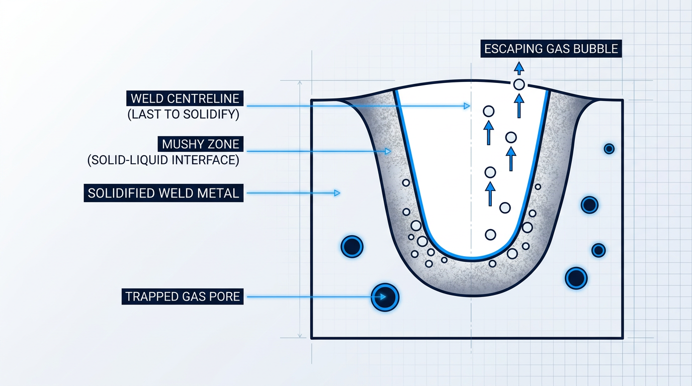
A note on terminology: a gas pore refers to a single trapped bubble, while porosity describes a population of multiple voids distributed through the weld volume.
In practice, and in most welding codes, both terms describe the same type of discontinuity — the distinction is one of scale rather than mechanism, and in most contexts calling the defect porosity is entirely correct regardless of whether one pore or many are present.
The gas that drives porosity comes from three broad source families: atmospheric contamination (nitrogen and oxygen from air that breaches or overwhelms the shielding); hydrogen introduced by moisture, oils, grease, or damp consumables; and gases generated by surface coatings or base metal chemistry, such as vapours from paint, primer, or galvanised zinc.
Each of these families has its own set of contributing conditions and failure modes, which the causes section explores in full — but understanding that all three ultimately work through the same entrapment mechanism is the key insight at this stage.
Structurally, porosity matters because each void reduces the effective load-bearing cross-sectional area of the weld, introduces stress concentration points at the pore boundaries, and degrades mechanical properties including tensile strength and fatigue life.
With that physical model in place, the next step is understanding the different forms porosity takes — because where pores form, how they are distributed, and whether they break the surface all have direct implications for detection, acceptance, and repair.
Types of Porosity in Welds
The pattern of porosity in a weld is rarely random noise — it is a diagnostic signal pointing back to a specific cause, and reading that pattern correctly is often the fastest route to a fix.
Porosity in welds presents in six recognised forms, each with a characteristic appearance, a typical location within the weld, and a cause signal that distinguishes it from the others.
Surface Porosity
Surface porosity — also called surface-breaking pores — consists of cavities that break through to the weld face and are therefore visible to the naked eye, making them the most immediately detectable form of porosity in a weld.
Their visibility can be misleading, however: visible surface pores frequently indicate a larger subsurface population, meaning the surface expression tends to understate the true extent of the defect.
The cause signal is severity — surface porosity is associated with gross shielding failure or heavy contamination rather than minor, transient disruption.
Distributed (Scattered) Porosity
Distributed porosity presents as multiple pores of varying sizes spread irregularly through the weld volume, with no clustering and no alignment along any particular axis.
The scattered, irregular pattern is the diagnostic signal: it points to a systemic, ongoing cause — such as a general shielding gas problem or widespread contamination across the joint — rather than a localised or momentary event.
Cluster Porosity
Cluster porosity consists of pores grouped together in an irregular pattern within a confined area, concentrated at one location rather than distributed through the weld.
This localised grouping is associated with faulty arc starts or arc stops, or with arc blow, and its key diagnostic value is precisely that concentration: it points to a momentary event at a specific location rather than a persistent condition.
Wormhole (Piping) Porosity
Wormhole porosity — also termed piping porosity — describes elongated cavities that are longer than they are wide, oriented approximately perpendicular to the weld face so that they run through the weld thickness rather than along it.
Forming these elongated tunnels requires large volumes of gas, which makes wormhole porosity a strong indicator of gross contamination or damp electrodes rather than a minor shielding disruption; on radiographs, the characteristic herringbone pattern is a well-recognised diagnostic marker for this type.
It is the most structurally significant form of porosity in a weld because the elongated cavities reduce weld cross-section more severely than spherical pores of equivalent volume, creating a larger plane of weakness through the joint — a consequence that will be examined further when weld integrity is covered later in this guide.
Aligned (Linear) Porosity
Aligned porosity presents as pores distributed along a line, typically at the weld interface or along the weld centreline.
The linear distribution reflects either a solidification geometry factor — the centreline is the last region to solidify, concentrating gas that cannot escape — or a repeating contamination source at a consistent position along the joint length.
Crater Pipe
A crater pipe is an elongated cavity at the weld finish crater, formed by rapid solidification and shrinkage when the arc is extinguished without adequate crater fill.
Technically, crater pipe is a shrinkage defect rather than a gas porosity defect, but it is included in this taxonomy because it commonly presents alongside gas porosity at the same location and is frequently misidentified — its diagnostic signal is unambiguous: it is always found at the weld finish crater and nowhere else.
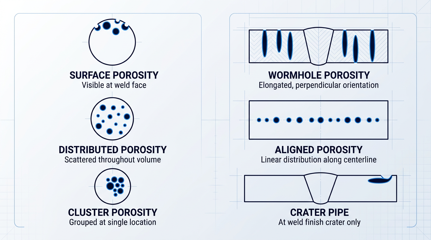
One further distinction cuts across this entire taxonomy and has direct consequences for inspection planning: surface porosity and surface-breaking wormhole porosity can be detected by visual inspection alone, but distributed, cluster, aligned, and subsurface wormhole porosity are invisible to the eye and require volumetric NDT — radiographic or ultrasonic testing — to detect and characterise.
Only surface-breaking pores are detectable by visual inspection. Distributed, cluster, aligned, and subsurface wormhole porosity all require radiographic or ultrasonic testing to find — a distinction that is critical to inspection planning and will be developed fully in the detection and acceptance criteria section of this guide.
With the six types established as a diagnostic vocabulary, the next question is what drives each of them — the causes and mechanisms behind porosity in welds, covered in the following section.
What Causes Porosity in Welds?
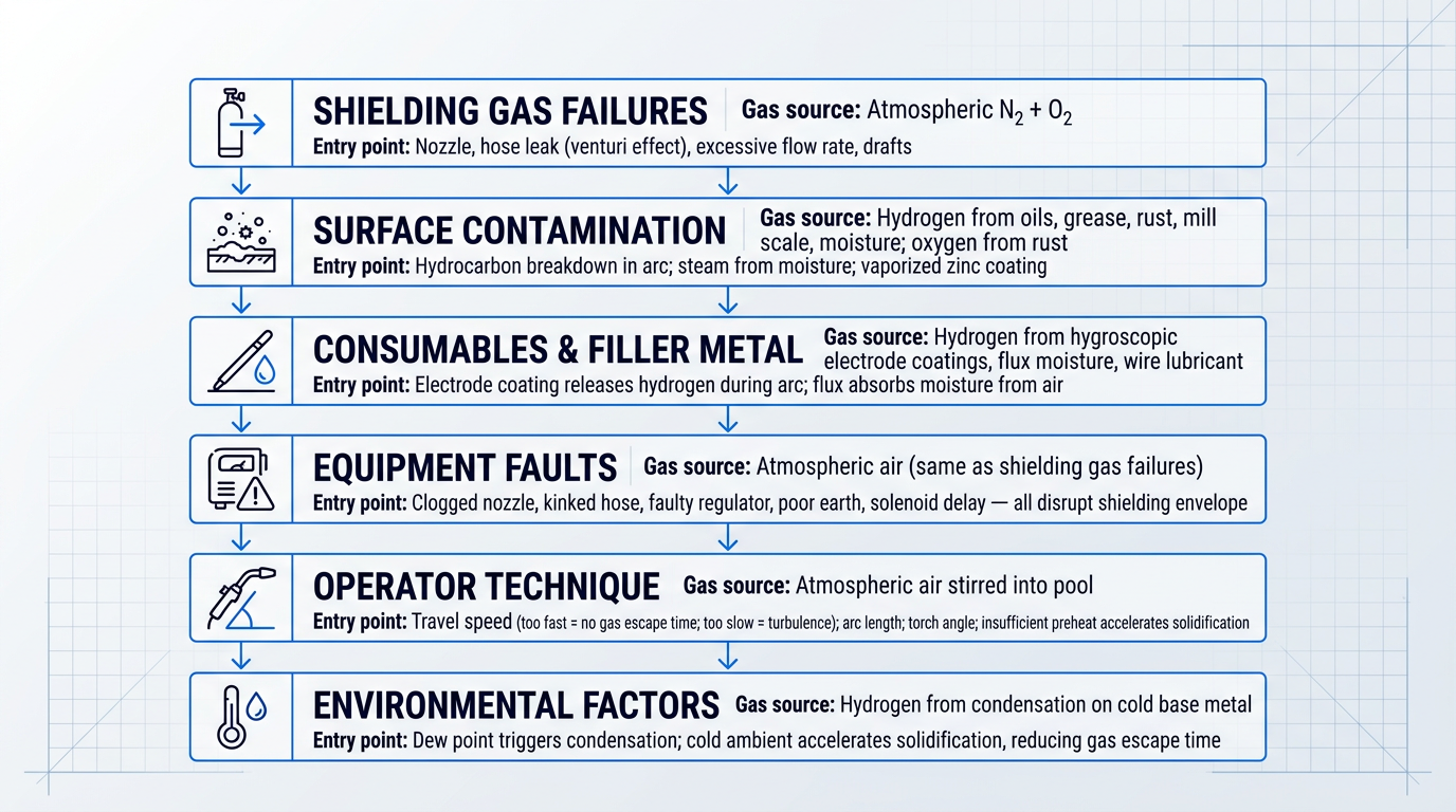
Porosity rarely has a single, obvious cause — and that is precisely what makes it frustrating to diagnose. The same symptom (gas cavities in the weld metal) can arise from a failing gas hose, a damp electrode, a contaminated base metal surface, or a travel speed that is slightly too fast.
Identifying the right cause requires understanding the underlying mechanism in each category, because the fix for one category will do nothing to address another.
Shielding Gas Failures
The shielding gas envelope exists to displace atmospheric nitrogen and oxygen from the weld pool — when that envelope fails, both gases dissolve into the molten metal and form pores as the pool solidifies. Even small amounts of air entrainment in the shielding gas stream are sufficient to cause distributed porosity, with higher levels of contamination producing gross surface-breaking pores.
What surprises many welders is that excessive flow rate is just as damaging as an insufficient one: too high a flow creates turbulence at the nozzle exit, which draws atmospheric air into the gas column rather than excluding it — the opposite of the intended effect.
Draughts and wind compound the problem by physically displacing the gas shield away from the pool, even when flow rate and equipment are correctly set — this is why outdoor or poorly screened welding environments consistently produce higher porosity rates.
On the equipment side, a pinhole leak in a gas hose can pull air into the stream via the venturi effect: the flowing gas creates a local pressure drop at the leak point, drawing atmospheric air inward rather than allowing shielding gas to escape outward. Spatter-clogged nozzles disrupt the laminar flow pattern of the gas, creating uneven coverage with gaps directly over the pool.
Surface Contamination
Oils and grease on the base metal are among the most controllable — and most underestimated — contributors to porosity in weld. When hydrocarbon chains encounter the intense heat of the arc, they break down and release atomic hydrogen, which dissolves readily into the molten weld pool; as the pool cools and solidifies, hydrogen solubility drops sharply and the gas is expelled, forming pores if solidification is faster than the gas can escape.
Rust and mill scale trap moisture within their porous structure, and that moisture converts to steam at arc temperatures, injecting both hydrogen and oxygen directly into the pool. Condensation on cold base metal acts by the same mechanism: water at the surface breaks down in the arc, releasing hydrogen into the melt.
Paint, primer, and other surface coatings generate combustion gases and fume as the arc passes over them, adding to the gas load in the pool. Galvanised zinc coatings present a particular challenge: zinc vaporises at a temperature well below the melting point of steel, so the coating turns to vapour before the base metal has fully melted — that vapour then struggles to escape through the already-solidifying pool above it. Both galvanised steel and aluminium carry material-specific contamination risks that are explored in depth in a later section.
Consumables and Filler Metal
Low-hydrogen electrodes such as E7018 are formulated specifically to limit hydrogen in the weld pool — but their coatings are hygroscopic, meaning they absorb moisture from the surrounding atmosphere when left exposed. Once moisture is absorbed, the electrode releases hydrogen during welding just as a contaminated base metal surface would, defeating the electrode's primary purpose and frequently producing wormhole porosity because the volume of gas released overwhelms the pool's capacity to expel it gradually.
An important nuance: cellulosic electrodes such as E6010 carry high inherent hydrogen content by design and must never be oven-dried in the way low-hydrogen types are — drying them alters their coating chemistry and affects arc performance. For flux-based processes such as FCAW and SAW, moisture absorbed into the flux is the principal hydrogen source, and filler wire stored improperly can accumulate drawing lubricant residues, surface oxides, and condensation that introduce the same contamination into the pool.
Equipment Faults
Equipment faults are particularly treacherous because they can produce porosity that looks identical to contamination or technique problems, sending the welder down the wrong diagnostic path.
- Clogged nozzles: Spatter build-up inside the nozzle disrupts laminar gas flow, creating uneven shielding coverage with gaps directly above the weld pool.
- Kinked or damaged hoses: Kinks restrict gas flow below the required rate; cracks or loose fittings allow air ingress via the venturi effect.
- Faulty regulators: A regulator delivering inconsistent pressure causes the flow rate to fluctuate, intermittently exposing the pool to atmosphere.
- Poor earth connections: A loose or corroded work clamp causes arc instability; an erratic arc makes the shielding envelope fluctuate, admitting atmospheric gas.
- Gas solenoid faults: Delayed or interrupted gas flow at arc start leaves the pool unshielded for the first moments of the weld, a common cause of cluster porosity.
Because these faults develop gradually and are often invisible during normal operation, systematic equipment checks are a necessary part of any thorough porosity diagnosis — not an optional step.
Operator Technique
Technique errors operate primarily through time: the weld pool has a finite window during which dissolved gas can float to the surface and escape before solidification locks it in place. Travel speed too fast deposits metal over gas bubbles before they can rise out; travel speed too slow creates excessive turbulence in the pool, stirring atmospheric gas into the melt rather than allowing a calm, well-shielded pool to form.
An incorrect torch angle disrupts the geometry of the gas coverage envelope, and a long arc length reduces shielding effectiveness because the gas column disperses before it fully covers the pool. Insufficient pre-heat on cold or thick base metal accelerates the solidification rate, compressing the time window for gas escape — especially significant in cold workshop environments where the base metal acts as a heat sink.
Environmental Factors
High ambient humidity raises the moisture load on both the base metal surface and consumables, but the critical threshold is the dew point: when the base metal temperature falls below the dew point of the surrounding air, condensation forms directly on the metal surface, introducing a hydrogen source that may not be visible to the welder.
Cold ambient conditions compound the problem through a second mechanism — lower base metal temperatures accelerate weld pool solidification, reducing the time available for dissolved gas to escape regardless of how that gas entered the pool in the first place.
Across surface contamination, consumable moisture, and environmental humidity, hydrogen is the dominant gas source in most non-shielding-failure porosity. Oils, rust, damp electrodes, wet flux, and condensation on cold metal all deliver hydrogen into the weld pool by different routes but through the same underlying mechanism — recognising this unifies the diagnostic picture and points toward a common family of controls.
With the cause categories established, the natural next question is what those trapped gas cavities actually do to the weld — how porosity translates into reduced strength, fatigue resistance, and leak tightness is what the following section addresses.
How Porosity Affects Weld Integrity
Understanding that porosity forms is only half the picture — the more pressing question for any fabricator or quality engineer is what it actually does to the joint once it is there.
The consequences span two distinct categories: mechanical performance (how the weld carries load) and functional integrity (whether the joint can contain pressure or fluid). Both matter, and they are not always correlated — a weld can pass a tensile test and still fail a leak test.
Mechanical consequences of porosity
The most direct consequence is a reduction in load-bearing cross-sectional area: a pore is a void, and a void carries no load.
As the area fraction of porosity in the fracture plane increases, tensile and yield strength degrade in proportion to the loss of sound metal — the relationship is straightforward because the mechanism is straightforward.
Ductility, however, is disproportionately sensitive to porosity, and this is a subtler and more dangerous consequence than the strength reduction alone would suggest.
The mechanism is inhomogeneous deformation: the material immediately surrounding a pore experiences far higher local strain than the bulk weld metal, because the pore cannot deform and the surrounding material must compensate.
This localised strain concentration accelerates failure initiation, meaning a weld can show nominally adequate tensile strength on a test report yet behave in a brittle manner under real loading conditions.
- Reduced tensile strength: Porosity removes load-bearing metal from the fracture plane; strength loss scales with the area fraction of voids present.
- Accelerated ductility loss: Local strain concentrations around pores cause earlier failure initiation than the tensile strength reduction alone would predict.
- Shortened fatigue life: Pore boundaries are stress concentration sites where cyclic cracks preferentially initiate, particularly under higher applied stresses.
- Position-dependent weakness: In horizontal welds, buoyancy concentrates pores in a plane normal to transverse loading, creating a coherent plane of weakness.
- Compromised leak tightness: Any through-thickness porosity path allows fluid or pressure to pass, regardless of the joint's structural strength.
Of these consequences, fatigue life reduction is particularly significant for structures subject to cyclic or dynamic loading — bridges, lifting equipment, and pressure vessels under thermal cycling.
The reason pores are such potent fatigue crack initiation sites lies in their geometry: the stress field peaks sharply at the pore boundary and diminishes into the surrounding matrix, creating a stress concentration that intensifies with each load cycle until a crack nucleates.
Weld position adds a further dimension that is easy to overlook: in horizontal-position welds, buoyancy causes gas pores to rise during solidification and concentrate near the upper face of the weld cross-section.
When that concentration aligns approximately normal to the direction of transverse loading, the result is not a random scatter of isolated voids but an effective plane of weakness — a far more serious condition than the same total pore volume distributed randomly through the weld.
Leak tightness: a separate failure mode
The mechanical consequences described above govern how a weld performs under load, but leak tightness is an entirely separate failure mode governed by connectivity rather than area fraction.
A single wormhole pore that traverses the full weld thickness, or a chain of interconnected pores that collectively bridges root to cap, provides a path for fluid or gas to pass — regardless of whether the joint would pass a tensile test.
This matters most in pipe fabrication, pressure vessel construction, and sanitary applications in the food, pharmaceutical, and dairy industries, where the functional requirement is containment, not just structural capacity.
The relationship between porosity and performance degradation is not binary — the severity depends on the extent, geometry, distribution, and nature of loading, which is why engineering practice treats porosity as a graduated concern rather than an automatic rejection criterion.
Small amounts of well-distributed internal porosity in a fillet weld may have a negligible effect on tensile performance. Wormhole-type porosity, a high area fraction, or pores concentrated in a plane normal to loading are a different matter entirely. The distinction between these cases is what makes quantified acceptance limits — rather than zero-tolerance rejection of all porosity — a rational engineering response.
For a quality engineer applying acceptance criteria intelligently, this graduated understanding is essential: the same total pore count can represent either an acceptable condition or a structurally significant defect, depending on where the porosity sits and how the joint is loaded.
The severity of these consequences is also not uniform across base materials — certain metals are inherently more susceptible to the porosity mechanisms that produce large pore volumes and unfavourable distributions, which is where the discussion turns next.
High-Risk Materials: Aluminium and Galvanised Steel
General porosity controls — clean base metal, sound shielding gas, dry consumables — are necessary but not sufficient for every material. Aluminium and galvanised steel each carry porosity risks rooted in their own chemistry and physics, and understanding those mechanisms is what separates persistent troubleshooting failure from a reliable fix.
Aluminium: The Hydrogen Solubility Problem
The core reason aluminium is disproportionately susceptible to porosity in weld comes down to hydrogen solubility: as TWI Global confirms, hydrogen solubility in molten aluminium is approximately 20 times higher than in solid aluminium.
As the weld pool solidifies, that dissolved hydrogen is forcibly expelled from the metal lattice — and if the cooling rate is too high for the resulting gas bubbles to escape before the pool freezes, they become trapped as porosity.
This means any hydrogen source in contact with the weld zone is a direct porosity risk. Hydrocarbon contamination — oils, grease, even skin oils from bare-hand contact — breaks down under arc heat to release atomic hydrogen into the pool. Drawing lubricant residues on filler wire carry the same risk: the lubricant decomposes in the arc and feeds hydrogen directly into the melt.
Moisture is equally problematic. The aluminium oxide layer that forms naturally on any exposed aluminium surface is hydrated — it holds chemically bound water that releases hydrogen when the arc heats it. Condensation on cold base metal or filler wire (when either falls below the ambient dew point) adds a further free-moisture hydrogen source.
The oxide layer creates a second, distinct complication beyond moisture. As confirmed by TWI Global and corroborated by Lincoln Electric, aluminium melts at approximately 660°C while its surface oxide (Al₂O₃) melts at approximately 2060°C — a differential so large that the oxide does not melt cleanly into the weld pool under normal welding conditions.
Because the oxide is porous in nature, it can absorb and trap contaminants before welding even begins. It must be removed mechanically using a dedicated stainless steel wire brush (never one shared with steel, which would transfer ferrous contamination) or by the cathodic cleaning action of AC TIG welding.
Critically, the oxide layer reforms very quickly after removal. Cleaned aluminium left exposed to the atmosphere will begin reabsorbing moisture into a freshly reformed oxide layer — which is why the interval between cleaning and welding matters as much as the cleaning itself.
Hydrogen solubility falls approximately 20 times as aluminium transitions from molten to solid (TWI Global). Every hydrogen source — hydrocarbons, moisture, oxide layer, filler wire lubricant — exploits this same mechanism. Eliminating hydrogen from the weld environment is the only reliable defence.
Aluminium-specific prevention priorities follow directly from these mechanisms, and the sequence matters as much as the individual steps.
- Degrease first: Apply a residue-free solvent before any mechanical cleaning. Brushing a contaminated surface smears hydrocarbons into the substrate, where the arc will later liberate them as hydrogen.
- Brush the oxide layer: Use a dedicated stainless steel wire brush immediately before welding to mechanically remove the oxide. Never share the brush with steel workpieces.
- Handle with clean dry gloves: Bare-hand contact deposits skin oils and sweat directly onto the prepared surface, reintroducing a hydrocarbon hydrogen source after cleaning.
- Store filler wire correctly: Keep wire in dry, sealed conditions to prevent condensation and lubricant contamination. Cold wire pulled into a warm, humid shop can condense moisture rapidly.
- Weld promptly after cleaning: The oxide layer reforms quickly on exposure to air. Delay between cleaning and welding allows moisture reabsorption into the fresh oxide, negating the preparation.
Each step in this sequence is anchored to a specific hydrogen-release pathway — skip any one of them and a hydrogen source remains active in the weld zone.
Galvanised Steel: Zinc Vapour and Joint Geometry
Galvanised steel presents a fundamentally different problem: the porosity source is not contamination in the conventional sense, but the zinc coating itself — an intended, functional part of the material.
As confirmed by both arcuscnc.com and Lincoln Electric, zinc boils at approximately 907°C, while steel melts at approximately 1,500°C. By the time the arc has heated the steel to its melting point, the zinc has already vaporised. That zinc vapour must escape upward through the molten weld pool before solidification; if it cannot clear the pool in time, it becomes trapped as internal or surface-breaking porosity.
This is why standard pre-weld cleaning protocols do not solve the problem: no amount of surface degreasing removes a metallurgically bonded zinc coating. The vapour source is intrinsic to the material.
Joint geometry dramatically affects how severe this porosity becomes. In a butt joint, zinc on the exposed weld zone surface has a relatively direct escape path upward through the pool to the atmosphere. In a lap joint, however, zinc exists on the sandwiched faying surfaces — the mating faces clamped together — and vapour generated there must travel laterally through the joint before it can rise through the full depth of the weld pool.
That extended, obstructed escape path is why lap joints in galvanised steel produce significantly more severe porosity than butt joints, and why the problem is particularly acute in structural and automotive fabrication where lap joints are the dominant joint type.
The most effective prevention is also the most direct: remove the zinc coating from the weld zone before welding. AWS D19.0 (Welding Zinc Coated Steel) addresses this directly — it calls for zinc to be removed at least 1 to 4 inches from either side of the intended weld zone on both sides of the workpiece, so that neither the weld metal nor the heat-affected zone contacts zinc during welding.
Where coating removal is impractical — field welding, high-production environments, or where post-weld corrosion protection of the stripped zone cannot be guaranteed — technique adjustments can reduce porosity severity, though they cannot eliminate it entirely. An oscillating or whipping torch motion ahead of the puddle volatilises zinc before the pool reaches it, giving vapour a chance to escape before the steel melts. A wider joint gap provides a physical vapour escape channel, particularly in lap joint configurations.
With the material-specific mechanisms for both aluminium and galvanised steel understood, the next section covers the complete prevention protocol applicable across all welding scenarios — integrating these material priorities into a comprehensive framework of surface preparation, consumable handling, equipment checks, and technique.
How to Prevent Porosity in Welds
Porosity in a weld is almost entirely preventable — the gap between a porous weld and a sound one is rarely a mystery of metallurgy, but a failure to apply the right controls consistently across four distinct levers: surface preparation, shielding gas management, consumable handling, and equipment and technique.
Surface Preparation: The Most Controllable Lever
Of all the contributing factors to porosity in weld, surface contamination is the most controllable — and the most underestimated.
Oils, grease, rust, mill scale, paint, and coatings are documented causes of porosity that exist before the arc is struck and can be completely eliminated before welding begins; the question is whether the cleaning method is thorough enough to do that job without introducing new problems.
The order of operations in surface preparation is not arbitrary — get it wrong and you compound the problem rather than solve it.
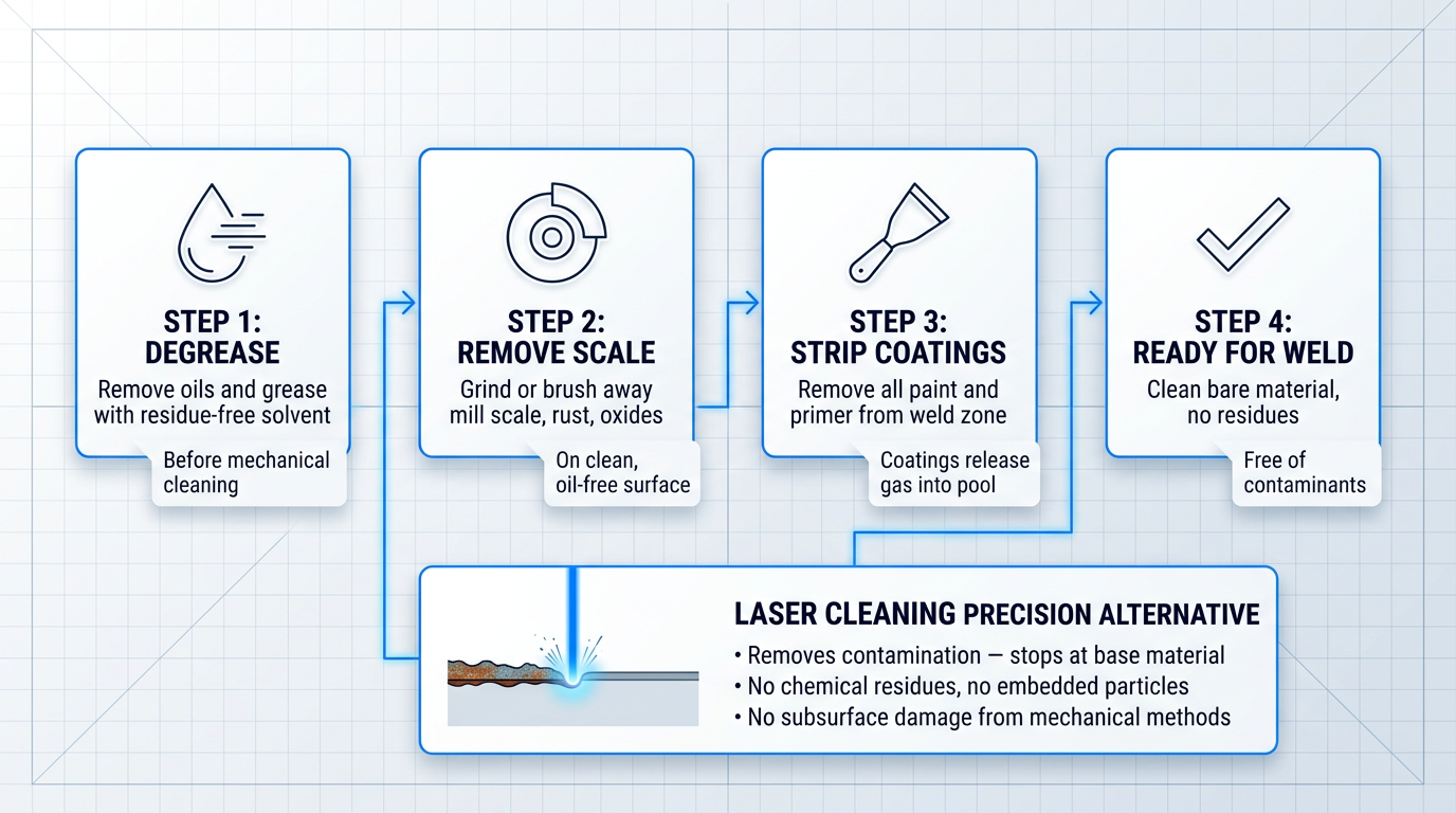
- Degrease first: Apply a residue-free solvent to remove oils and grease before any mechanical cleaning. Grinding or wire brushing a contaminated surface smears contaminants into the substrate.
- Remove oxides and scale: After degreasing, remove mill scale, rust, and surface oxides by grinding, wire brushing, or chemical methods — working on a surface already free of oils.
- Strip paint and primer: Remove all paint and primer from the weld zone. Coatings that survive into the arc release gas directly into the weld pool.
- Aluminium: brush and weld promptly: After solvent cleaning, use a dedicated stainless steel wire brush on aluminium. Weld as soon as possible — the oxide layer reforms quickly on a freshly cleaned surface.
The method of cleaning matters as much as the act of cleaning itself — solvent residues, embedded abrasive particles, and subsurface damage from aggressive mechanical methods can all contribute to gas entrapment in the finished weld.
Laser cleaning has emerged as a precision alternative to solvent wiping and mechanical grinding for pre-weld surface preparation, and quality-focused fabrication operations are increasingly adopting it for exactly this reason: the laser beam removes contamination — oils, rust, mill scale, oxides, paint, and coatings — and stops at the base material, leaving the substrate intact with no chemical residues, no embedded abrasive particles, and no subsurface damage that could itself become a source of gas entrapment.
Woodrow Scientific's ELASER is a portable industrial fibre laser cleaning system built around this principle, and it is notable for its world-first reduced hazard zone (RHZ) technology: WSL's patented approach collapses the laser hazard zone to a fraction of conventional size, enabling use in open workshops and mixed-use facilities without sealing off the area — a practical barrier that has historically limited laser cleaning to dedicated enclosures.
The ELASER's handheld scanner weighs under 3 kg with up to 50 m of delivery cable, so a single operator can cover large or complex weld preparations without a fixed installation; with no consumables and a total cost of ownership that compares favourably over time, it is a compelling option for operations running high cleaning volumes.
For production environments where parts move through a cleaning station repeatedly, Woodrow Scientific's AutoLASE takes a different approach: load the part, and the system's 3D machine-vision software scans it, builds a spatial map, and generates the cleaning path automatically — no programming, no path-setting, no specialist knowledge of part geometry required.
AutoLASE can also be configured with WSL's RHZ technology, removing the need for an enclosure entirely — a capability exclusive to WSL worldwide, making automated laser cleaning viable in facilities where a conventional enclosed cell would not be practical.
Both systems are CE and UKCA certified, designed and built in-house by WSL as the only UK-based laser cleaning manufacturer — which means engineering support, spares, and product improvements come directly from the people who built the machine, not from a reseller with a rebadged import.
Shielding Gas Management
A correctly set shielding gas flow rate is the difference between a weld pool protected from atmospheric contamination and one that is not — and both extremes cause porosity: too low and the pool is exposed to nitrogen and oxygen; too high and turbulence draws atmospheric gas into the shield.
Use a flow meter rather than a pressure gauge alone to verify the actual volumetric flow rate in cfh or l/min for the specific process and application — a pressure gauge does not confirm what is reaching the torch.
- Purge gas lines before welding: Moisture can condense inside hoses during storage. Purge the line before striking the arc to expel any accumulated condensation.
- Inspect all fittings and connections: Check hose connections and regulator fittings for leaks — a small air ingress at any joint undermines the entire gas shield.
- Use the correct gas for the process: Match the shielding gas type to the base material and welding process. An incorrect gas mix introduces reactive species directly into the weld pool.
- Shield the work area from draughts: Wind and air movement can displace a correctly set gas shield. Screens or baffles are necessary when welding in exposed or high-traffic areas.
Even a well-configured gas system is defeated by environmental conditions — draught protection is not optional in exposed or outdoor welding situations, and it is frequently overlooked as a root cause when flow rate and equipment both check out.
Consumable Handling and Storage
Low-hydrogen electrodes such as E7018 must be stored in sealed containers or electrode ovens and re-dried if they have been exposed to humidity — moisture absorbed by the flux coating is a direct source of hydrogen in the weld pool.
Cellulosic electrodes are the exception: these must not be re-dried, as their moisture content is part of their designed operating chemistry.
Filler wire should be stored in dry conditions within the manufacturer's specified temperature and humidity range, and both wire and electrodes should be handled with clean, dry gloves — skin oils and sweat introduce hydrogen directly into the weld pool at the point of contact.
Equipment Maintenance and Technique
Spatter build-up inside the nozzle is one of the most common and easily prevented causes of disrupted gas coverage — clean nozzles regularly as part of routine maintenance, not reactively when porosity has already appeared.
Inspect gas hoses for kinks, cracks, and loose connections on a scheduled basis; verify regulator function and confirm the earth (work) connection is clean and secure, as a poor earth can cause arc instability that contributes to gas entrapment.
Operator technique is equally consequential: maintain correct travel speed, torch angle, and arc length for the process — deviating from any of these disrupts the gas shield and can introduce atmospheric contamination even when all equipment is functioning correctly.
In GMAW, the push (forehand) technique lays the gas blanket ahead of the arc rather than trailing it, providing better atmospheric protection for the weld pool — a pull technique in the same process leaves the pool more exposed.
Where the welding procedure specification or base material requirements call for it, apply the specified pre-heat: slowing the cooling rate gives dissolved gases more time to escape the weld pool before solidification traps them.
Shielding gas failures, technique errors, and equipment faults all require active management during welding. Surface contamination is different: it can be completely removed beforehand. That distinction makes pre-weld cleaning the single highest-leverage intervention in any porosity prevention programme — yet it is the step most often treated as routine rather than critical.
Even with all four levers applied correctly, porosity can still occur — weld metal is complex, and no prevention regime eliminates every variable in every situation.
The next question is how to find it when it does, and what the applicable welding codes say about when it constitutes a reject — both of which are covered in the section that follows.
Detecting Porosity and Understanding Acceptance Criteria
Prevention is the primary control strategy for porosity in a weld — but prevention is never perfect, and every quality engineer eventually faces the same two questions: did I find all of it, and what do I do with what I found?
Visual inspection is the starting point for any weld examination, and it costs nothing beyond a trained eye and adequate lighting. Its hard boundary, however, is equally clear: visual examination detects only surface-breaking porosity — pores open to the weld face and surface-breaking piping porosity. Anything subsurface is invisible to the naked eye, no matter how thorough the examiner.
The professional nuance that separates experienced inspectors from novices is this: visible surface porosity frequently understates the true extent of the defect. Surface pores are often the tip of a larger subsurface population — the visible portion is a signal, not a census.
NDT methods for porosity detection
Volumetric non-destructive testing methods extend inspection capability beyond what the surface can reveal, and selecting the right method for the application requires matching technique to material, weld configuration, and the criticality of the joint.
- Penetrant Testing (PT) and Magnetic Particle Inspection (MPI): Surface-breaking imperfections only. Both methods enhance and reveal what is already open to the surface; neither can detect subsurface porosity.
- Radiographic Testing (RT): The most effective volumetric method for detecting and characterising porosity. Wormhole porosity produces a characteristic herringbone appearance on radiographs, aiding identification. Most commonly specified for critical welds.
- Ultrasonic Testing (UT): Detects subsurface porosity volumetrically. Practical where RT is impractical due to site constraints or radiation safety, though generally less sensitive to small individual pores than RT.
ISO 17635:2025 (Edition 4) is the current international framework practitioners use to select the appropriate NDT method — matching technique to code requirements, material type, weld thickness, welding process, and the extent of testing required. It does not set acceptance levels directly, but it is the practitioner's guide to making a defensible method selection.
Surface pores are frequently indicative of a larger subsurface cluster. Volumetric NDT is needed to characterise the full extent in any critical application — and because even volumetric methods have detection thresholds for very small pores, prevention remains a more reliable quality control strategy than detection alone.
Acceptance criteria: AWS D1.1 and ISO 5817
A quality engineer who understands the applicable acceptance criteria is operating at a fundamentally different level from one who rejects every visible pore. The codes set quantified limits, not zero-porosity demands — and knowing where those limits sit, and why, is a marker of professional competence rather than a technicality to be memorised.
Under AWS D1.1, the visual inspection acceptance criteria in Table 6.1 address piping porosity specifically — the elongated, depth-extending form whose major dimension lies approximately perpendicular to the weld face. Other forms of surface-breaking porosity are not specifically rejectable under D1.1 visual criteria alone. For CJP groove welds in butt joints transverse to the direction of computed tensile stress, Table 6.1 permits no visible piping porosity. A critical and commonly misunderstood distinction: internal porosity in CJP groove welds is not governed by visual criteria at all — it falls under the radiographic and ultrasonic acceptance criteria in Clause 6 of D1.1, which set separate dimensional and frequency limits for subsurface discontinuities.
ISO 5817 is the complementary international standard, covering fusion-welded joints in steel, nickel, titanium and their alloys (it is not a universal standard — aluminium alloy welds, for example, fall under ISO 10042). It defines three quality levels: B (stringent), C (intermediate), and D (moderate), each with specific dimensional limits for porosity. The quality level applied to a given weld is not chosen arbitrarily; it is driven by service conditions including static and fatigue loading, pressure, corrosion environment, and thermal exposure.
The engineering rationale behind code limits — rather than a zero-porosity requirement — is grounded in research. TWI has demonstrated that porosity in fillet welds must represent more than 5% cross-sectional area loss before tensile strength is meaningfully reduced. Codes reflect this reality: not all porosity is a structural concern, and a quality engineer who applies that understanding is exercising engineering judgement, not simply pattern-matching against a checklist.
With the acceptance criteria understood, the next question is what to do when porosity exceeds them — and how to address the operator knowledge gaps that allow it to get that far in the first place.
Repairing Porosity and the Role of Operator Training
Finding porosity that exceeds the applicable code limits is not the end of the job — it is the start of a decision process that requires both procedural discipline and a clear understanding of why the defect formed in the first place.
The first and most important professional competence point: not all porosity requires repair. Repair is triggered by the applicable welding code or specification's acceptance criteria — porosity within those limits requires no corrective action, and reflexively grinding out every visible pore reflects a misunderstanding of the standard, not rigour.
Why You Cannot Simply Weld Over Porosity
Welding over existing porosity without first removing the affected metal fails on three levels: the defect is buried beneath the new pass rather than eliminated, the original gas source remains in place, and the new pass is deposited into the same conditions that produced the original defect — making it highly probable the new weld inherits the same problem.
This is why the fix must address two things simultaneously: physically removing the porous metal and eliminating the root cause.
The porous metal must be removed back to sound metal, and the root cause must be identified and corrected. Satisfying only one of these conditions will not produce a sound weld — the defect will recur.
When porosity is localised to a specific zone, the repair follows a defined sequence that mirrors the rigour of the original welding procedure.
- Remove the affected metal: Grind or arc-gouge the porous zone back to sound metal. Partial removal is insufficient — all porous material must be eliminated.
- Verify the excavation: Inspect the prepared area visually and by NDT where required by the applicable WPS or code before proceeding.
- Eliminate the root cause: Apply the same pre-weld cleaning and preparation standards as the original weld. The contamination or moisture source must be resolved.
- Re-weld to the WPS: Re-weld in full compliance with the agreed Welding Procedure Specification — no relaxed standards apply to repair passes.
The key discipline in this sequence is that the repair weld is held to exactly the same preparation standards as the original — because the same failure modes remain possible if the root cause has not been genuinely resolved.
When porosity is distributed throughout the weld rather than confined to a localised area, the entire weld must be removed and the joint re-prepared before any re-welding begins.
Attempting to repair widespread porosity piecemeal, without first identifying and correcting the cause, will reproduce the defect in the new weld — this is the harder, more time-consuming outcome, and precisely the reason root cause identification matters before the arc is ever struck.
Once the repair weld is complete, it must be inspected against the same acceptance criteria as the original weld — there is no separate or relaxed standard for repaired joints. In many code-governed applications, the repair, the root cause identified, and the corrective action taken are expected to be formally documented as a matter of professional practice.
Training as a Systemic Prevention Lever
The majority of porosity causes are fully within the control of a knowledgeable operator — and defect rates in practice tend to reflect how well the operator understands the underlying mechanisms, not merely whether a checklist was followed.
An operator who understands why damp electrodes cause porosity will handle consumables correctly in every situation, including ones no checklist anticipated; one who only knows the rule will fail when the rule is ambiguous or the situation is novel.
In operations where porosity keeps recurring despite new procedures and equipment checks, the most durable corrective action is usually a structured training intervention that closes the root knowledge gap — not a new checklist, and not new equipment.
Checklist compliance produces brittle quality outcomes; understanding the mechanisms that drive gas entrapment in the weld pool produces durable ones — and that understanding is what separates a welder or quality engineer who solves the problem from one who keeps repairing the symptom.
With repair procedure and the systemic role of operator knowledge both covered, the final step is consolidating the core controls that keep porosity in a weld from forming in the first place — which is where this guide concludes.
Conclusion
Keeping porosity under control
At its core, porosity in a weld is a gas-entrapment problem — and that framing matters, because it means every variable that lets gas in or traps it in place is something an informed operator can address.
The controls are well understood and genuinely within reach: clean base metal, sound shielding, dry consumables, and technique that gives the pool time to breathe.
Where porosity keeps recurring despite that knowledge, structured training is the fix that checklists alone cannot provide — and for acceptance decisions, the applicable code is always the right place to start.
Frequently asked questions about porosity in welds
Common questions about porosity in welding, covering causes, acceptance criteria, repair, and terminology.
If the porosity exceeds the acceptance criteria of the applicable code or specification, grind or gouge out the affected area back to sound metal, identify and eliminate the root cause — whether contamination, shielding gas failure, or consumable moisture — then re-weld in accordance with the welding procedure specification (WPS). If the porosity is within code tolerance, no repair is required. Not all porosity is automatically a reject. Removal must be thorough enough to eliminate all porous material, not just the visible surface pitting. Critically, the root cause must be corrected before re-welding — applying a new pass over an unresolved contamination source or shielding gas fault risks reproducing the same defect in the repair weld.
Acceptance criteria depend on the applicable welding code and the weld type — there is no single universal limit. Under AWS D1.1, visual inspection criteria address piping porosity with specific size and frequency limits; internal porosity is evaluated under radiographic and ultrasonic acceptance criteria in Clause 6. ISO 5817 defines three quality levels — B (stringent), C (intermediate), and D (moderate) — with dimensional limits for porosity scaled to service conditions. The appropriate quality level or code clause depends on the application, service environment, and the engineer of record. Consult the applicable standard directly for the precise limits that govern your work.
Welding over existing porosity without removing it traps the defect beneath the new weld metal. The gas source — contamination, moisture, or a shielding gas failure — remains in place, and the new pass is exposed to the same conditions that caused the original porosity. The porous metal and its cause must both be addressed before re-welding. Beyond simply burying the defect, the heat of the new pass agitates the contaminated zone, which can worsen the problem rather than resolve it. The repair weld may inherit the same porosity, leaving the joint in a worse condition than before.
The primary cause is moisture pick-up in the electrode coating. E7018 is a low-hydrogen electrode designed to minimise diffusible hydrogen in the weld, but its flux coating is hygroscopic. When exposed to humidity outside of sealed packaging or a heated rod oven, it absorbs moisture. That moisture breaks down under arc heat to release hydrogen, which dissolves in the molten weld pool and becomes trapped as porosity during solidification — directly undermining the electrode's low-hydrogen purpose. E7018 electrodes should be stored in sealed containers or a heated electrode oven. If humidity exposure is suspected, re-dry according to the manufacturer's specification before use. Note that re-drying guidance applies to low-hydrogen electrodes; cellulosic electrodes should not be re-dried.
Not always, but visible surface porosity is frequently indicative of a larger subsurface population — the visible portion tends to understate the true extent of the defect. Surface-breaking pores are those that escaped the solidifying weld pool; pores that formed but did not reach the surface remain trapped internally and are invisible to visual inspection. Where surface porosity is detected in a critical application, volumetric NDT — radiographic testing (RT) or ultrasonic testing (UT) — is used to characterise the full extent of the porosity population before any repair decision is made.
Both terms describe gas-filled cavities in solidified weld metal. A gas pore typically refers to a single bubble or void; porosity refers to the presence of multiple such cavities, whether distributed, clustered, or elongated. In most practical welding and code contexts the distinction carries little weight, and the terms are used interchangeably. Standards such as ISO 5817 and AWS D1.1 use "porosity" as the umbrella term covering individual pores and populations of pores alike.