

Introduction
If you are reading this, you are probably not new to polarization-maintaining fibre — you are working with it, evaluating it, or trying to understand why a system is not behaving the way it should.
That distinction shapes everything that follows: this is a guide for practitioners, not a primer for the curious.
The coverage moves from the physics of how polarisation is preserved, through the principal fibre architectures and their real engineering trade-offs, into performance metrics and the measurement disciplines that make those metrics meaningful.
It then turns to the handling side — splicing, connectorisation, environmental factors — before closing with the application contexts where PM fibre is not just useful but structurally necessary.
TL;DR
PM fibre performance is not settled at the point of specification. The gap between what a datasheet promises and what a deployed system delivers is almost always the product of decisions made downstream: which architecture was chosen, how carefully measurements were taken, how precisely the fibre was handled, and how well the installation was designed for environmental stability.
This article covers:

The physics of polarisation maintenance and birefringence
PM fibre designs and their engineering trade-offs
Polarisation extinction ratio, crosstalk, and beat length
Measuring PER and crosstalk — and common errors
PM-specific splicing, connectorisation, and environmental stability
Applications where PM fibre is necessary and why
What Is Polarization-Maintaining Fibre?
Connect a standard single-mode fibre to a polarisation-sensitive component — a coherent receiver, an interferometer, a fibre optic gyroscope — and you immediately face a fundamental problem: the polarisation state of the light arriving at the output is unpredictable, time-varying, and essentially uncontrollable.
Standard SMF supports two orthogonally polarised modes, the degenerate HE₁₁ˣ and HE₁₁ʸ modes. In a theoretically perfect, circularly symmetric fibre these two modes propagate at identical phase velocities and do not exchange energy.
Real fibres are never perfectly symmetric. Manufacturing tolerances, residual stress introduced during fibre drawing, and trace impurities all create small, random departures from ideal circular geometry, producing small, random birefringence distributed along the fibre length.
Environmental perturbations — bending, twisting, lateral pressure, and temperature gradients — add further, time-varying birefringence on top of this residual fabrication birefringence, continuously coupling energy between the two polarisation modes in an unpredictable way.
The cumulative result is that the output polarisation state of a standard SMF fluctuates randomly with time, fibre routing, and ambient conditions. No amount of careful launch alignment can stabilise it.
PM Fibre: Intentional Birefringence as the Solution
A polarization-maintaining fibre is a specialty single-mode fibre — it supports exactly the same two orthogonally polarised HE₁₁ modes as standard SMF, and it is genuinely single-mode in the sense that only the fundamental mode propagates.
What distinguishes PM fibre is not the elimination of one polarisation mode, but the deliberate suppression of mode coupling between the two modes through the introduction of a large, engineered refractive index difference between them.
This engineered difference is intentional birefringence: the propagation constants of the two polarisation modes are made so different from each other that any perturbation capable of driving coupling in a standard SMF is orders of magnitude too small to efficiently transfer power between the modes.
Light launched into one polarisation mode encounters such a large barrier — the mismatch in propagation constant — that it remains in that mode along the full fibre length, locking the polarisation state to the axis of launch.
The Slow Axis, Fast Axis, and the Alignment Condition
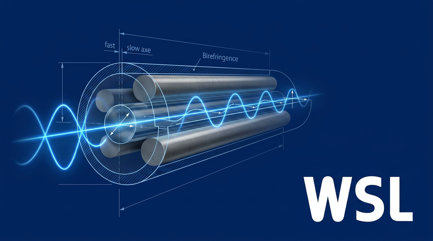
The intentional birefringence creates two distinct principal transmission axes. The slow axis is the axis with the higher refractive index, along which light propagates more slowly; the fast axis carries the lower refractive index and correspondingly higher propagation velocity.
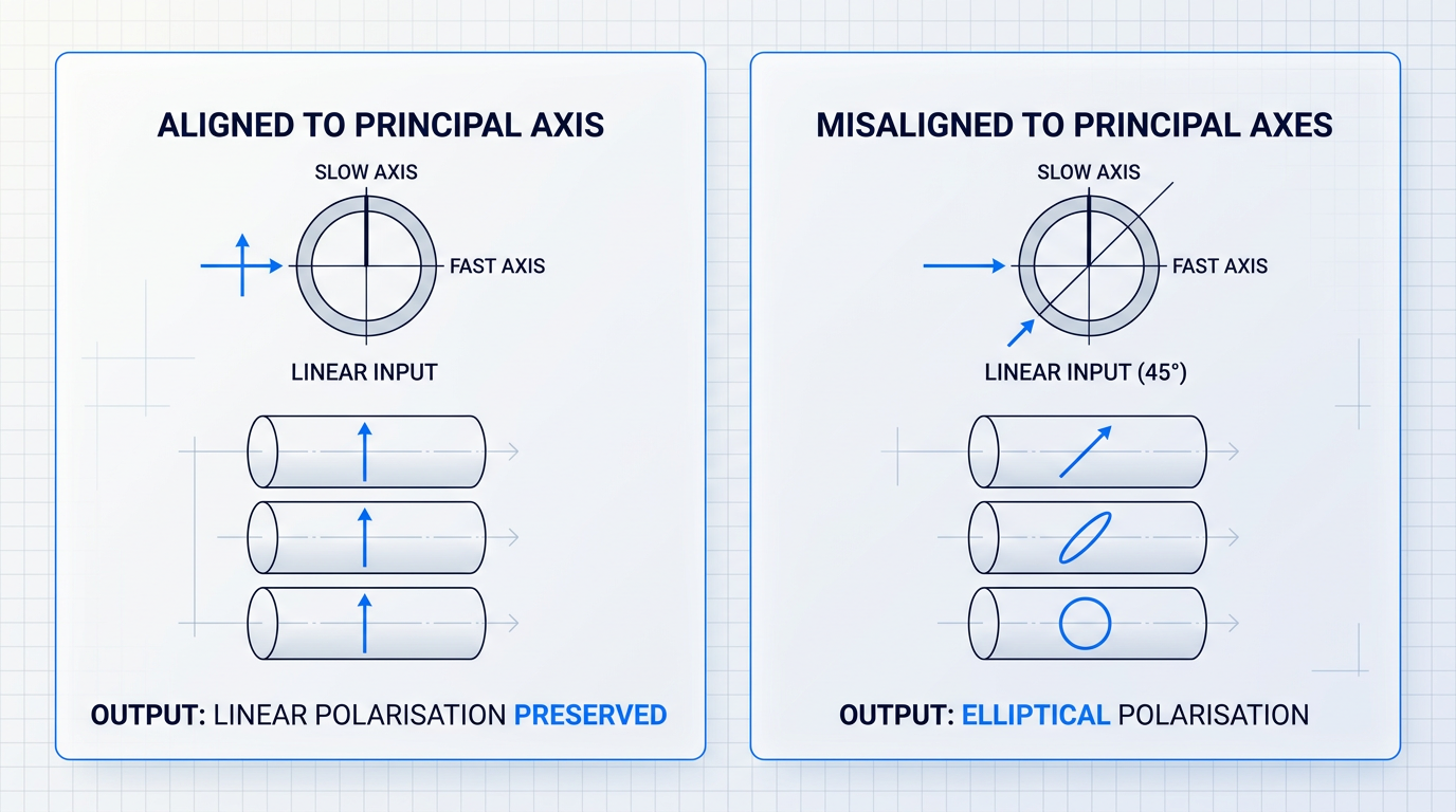
PM fibre preserves polarisation only when the input light is linearly polarised and aligned precisely to one of these two principal axes — either the slow axis or the fast axis.
If the input polarisation is misaligned, even slightly, a fraction of the optical power is launched into each axis simultaneously. The two components accumulate a phase difference as they propagate at different velocities, and the output polarisation state evolves into an elliptical, time-varying form.
PM fibre does not preserve arbitrary polarisation states — it preserves linear polarisation aligned to a principal axis. This distinction is critical and a common source of confusion in system design.
The strength of a PM fibre's birefringence is characterised by its beat length (L_B), defined as the distance along the fibre over which the phase difference between the two polarisation modes accumulates to 2π.
Physically, beat length is the distance over which the polarisation state would complete one full cycle of evolution if light were launched at 45° to the principal axes — a shorter beat length means a larger birefringence, faster phase accumulation, and stronger resistance to mode coupling.
Beat length is related to the fibre's modal birefringence B by the expression L_B = λ/B, where λ is the operating wavelength and B = n_slow − n_fast is the refractive index difference between the two axes.
High-birefringence PM fibres achieve beat lengths of 1–5 mm at 1550 nm (e.g. Thorlabs PM1550-XP: ≤5 mm). Standard SMF-28, measured at 1550 nm, has a beat length of approximately 11.8 m — more than three orders of magnitude longer. This gap is why intentional birefringence so effectively suppresses polarisation fluctuation.
The two physical mechanisms by which intentional birefringence is engineered into a PM fibre are fundamentally distinct, and different fibre designs exploit them in different proportions.
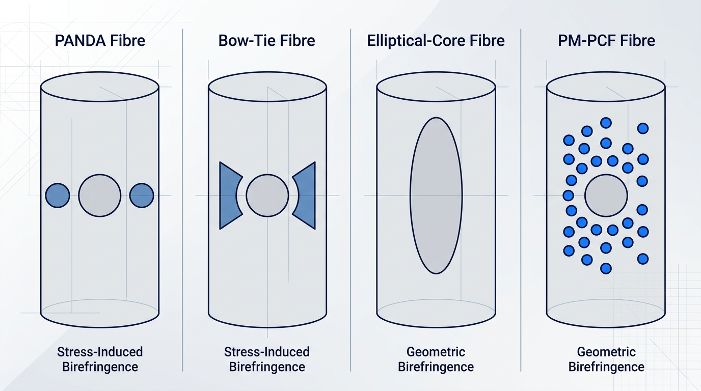
- Stress-induced birefringence: Asymmetric mechanical stress from structural elements with mismatched thermal expansion creates a refractive index difference via the photoelastic effect, frozen in during fabrication cooling.
- Geometric birefringence: A non-circular core cross-section presents a different waveguide geometry to each orthogonal polarisation mode, producing different effective refractive indices for each.
Both mechanisms contribute to the total modal birefringence B, which can be expressed as B = B_s + B_g, where B_s is the stress-induced birefringence component and B_g is the geometric birefringence component.
In practice, achieving purely geometric birefringence is challenging, since non-circular core geometries typically also introduce asymmetric stress distributions — meaning both components are present to some degree in most fibre designs.
With the physics of intentional birefringence established, the natural next question is how different fibre structures actually implement these mechanisms — and what engineering trade-offs each approach involves.
PM Fibre Architectures: Structures, Mechanisms, and Trade-offs
Knowing that intentional birefringence preserves polarisation is the starting point — the harder question is which physical structure should create that birefringence, and what engineering consequences follow from that choice. The four principal polarization-maintaining fibre architectures each answer this question differently, and each answer carries a distinct set of trade-offs that practitioners must weigh against their application's dominant constraints.
PANDA Fibre
PANDA fibre places two circular boron-doped stress rods symmetrically on either side of the core within the cladding — a cross-section that resembles a panda's face and gives the design its name. The stress rods have a higher coefficient of thermal expansion than the surrounding cladding glass; as the fibre cools after drawing, the rods contract more than the cladding, placing the core under asymmetric tension along one axis and generating stress-induced birefringence.
The cylindrical geometry of the stress rods is straightforward to maintain with high uniformity over long draw lengths, and it is this fabrication advantage — not any inherent optical superiority — that has made PANDA the dominant PM fibre design in telecommunications and the most widely produced PM fibre type.
Because the birefringence originates in differential thermal stress, it is temperature-dependent by nature: as temperature rises, the stress relaxes, beat length increases, and polarisation-holding capacity is reduced.
Bow-Tie Fibre
Bow-Tie fibre replaces PANDA's circular rods with wedge-shaped (trapezoidal prism) stress-applying regions, positioning the stress material closer to the core than the rod geometry allows — the same stress-induced birefringence mechanism, implemented with a different spatial relationship between stressor and core.
That closer proximity can yield higher birefringence per unit stress element, making Bow-Tie capable of stronger birefringence than PANDA for a given fibre geometry in some configurations.
The wedge geometry introduces meaningfully greater fabrication complexity than PANDA's cylindrical rods, and it creates a known risk of cracking under severe mechanical stress or tight bending — a real engineering constraint that must be factored into cable routing and deployment planning, not treated as a minor caveat.
Elliptical-Core Fibre
Elliptical-core fibre achieves birefringence through a fundamentally different route: the core cross-section is non-circular, so the two orthogonally polarised HE₁₁ modes propagate through different effective waveguide geometries and therefore at different phase velocities. This is geometric birefringence, with no stress-applying elements involved.
A significant and frequently underestimated engineering consequence is the divergence between group birefringence and phase birefringence: in elliptical-core designs this divergence is substantially larger than in stress-induced designs such as PANDA and Bow-Tie, complicating dispersion characterisation and the modelling of dispersive properties in ways that simply do not arise with stress-rod architectures.
Because geometric birefringence does not depend on differential thermal stress, elliptical-core fibre has lower temperature sensitivity than either PANDA or Bow-Tie — making it preferable for wide-temperature-range sensing applications such as fibre optic gyroscopes.
Photonic Crystal PM Fibre
Photonic Crystal Fibre (PM-PCF) achieves birefringence through an asymmetric arrangement of air holes in the microstructured cladding surrounding the core — asymmetry in hole size, spacing, or arrangement breaks the circular symmetry of the waveguide and creates geometric birefringence through a mechanism distinct from both the stress-rod and elliptical-core approaches.
PM-PCF designs can reach very high birefringence levels, and the air-hole geometry offers a degree of design freedom unavailable in solid-glass fibres: birefringence, dispersion, and mode field properties can be tuned simultaneously by adjusting the hole pattern.
The practical system integration constraint is significant: PM-PCF cores are substantially smaller than standard single-mode fibre, resulting in a fundamental mode field diameter mismatch that limits splice efficiency and compatibility with standard SMF components throughout the system.
Like elliptical-core fibre, PM-PCF's birefringence is geometric in origin rather than thermally driven, so it exhibits lower temperature sensitivity than the stress-induced designs.
Comparing the Designs: A Trade-off Framework
Across all four designs, temperature sensitivity divides cleanly along the line of birefringence mechanism: stress-induced designs are inherently sensitive to temperature because the differential thermal stress that creates their birefringence diminishes as temperature rises, while geometric designs are not bound by this constraint.
PANDA and Bow-Tie are fundamentally temperature-sensitive because their birefringence decreases as thermal stress relaxes with rising temperature. Elliptical-core and PM-PCF designs, relying on geometry rather than stress, are not subject to this constraint — making them the preferable choice whenever polarisation stability across a wide temperature range is the dominant requirement.
The table below maps all four designs across the key trade-off axes a practitioner must evaluate when selecting a PM fibre for a given application.
| Design | Birefringence Level | Temperature Sensitivity | Bend / Crack Risk | Fabrication Complexity | MFD Compatibility with Standard SMF |
|---|---|---|---|---|---|
| PANDA | High | High — stress relaxes as temperature rises | Low bend risk; no cracking risk | Moderate — cylindrical rods maintain uniform geometry over long draw lengths | Good — MFD closely matched to standard SMF |
| Bow-Tie | Very high (potential) | High — same stress-induced mechanism as PANDA | Elevated cracking risk under tight bending or severe mechanical stress | High — wedge geometry harder to maintain uniformly than cylindrical rods | Good — MFD closely matched to standard SMF |
| Elliptical-core | Moderate to high | Low — geometric mechanism not driven by thermal stress | Low; no stress elements present to crack | Moderate — elliptical preform geometry adds complexity vs. circular core | Good — MFD broadly compatible with standard SMF |
| PM-PCF | Very high | Low — geometric mechanism not driven by thermal stress | Low crack risk; microstructure requires careful handling | High — air-hole pattern requires precise preform stack and draw control | Limited — substantially smaller MFD creates mode field mismatch at splices |
Multi-axis comparison of the four principal PM fibre designs to support application-driven selection decisions
PANDA's position in this table explains its fabrication-driven market dominance: moderate complexity, good SMF compatibility, and reliable high birefringence make it the lowest-friction choice for telecom and most laboratory applications where temperature range is not the binding constraint.
Bow-Tie's potential birefringence advantage is real, but the cracking risk and higher fabrication complexity narrow its preferred application space to scenarios where that extra birefringence margin is genuinely needed and routing conditions can be controlled.
Elliptical-core and PM-PCF are the natural choices when temperature stability is the dominant requirement — but each arrives with its own constraint: elliptical-core's group/phase birefringence divergence complicates dispersion measurement, while PM-PCF's mode field mismatch demands careful attention at every splice and connection point in the system.
Selecting the right design is ultimately an exercise in identifying which constraints the application cannot tolerate and matching those to the architecture that leaves them off the table — and doing that well requires knowing how to characterise and verify the performance each design actually delivers, which is where polarisation extinction ratio, crosstalk, and beat length come in.
PER, Crosstalk, and Beat Length Explained
Beat length, polarisation extinction ratio, and crosstalk are not three ways of saying the same thing — they measure fundamentally different aspects of polarisation performance, are used in different contexts, and appear in different places on a datasheet. A practitioner who conflates them will misread manufacturer specifications and make poor system-level design decisions.
Beat length, PER, and crosstalk: what each measures
Beat length is the one parameter that belongs to the fibre itself, independent of how it is deployed, routed, or connectorised.
Physically, it is the distance along the fibre over which the phase difference between the two orthogonally polarised modes accumulates to 2π, equivalent to the ratio of the operating wavelength to the modal birefringence (L_B = λ / Δn_eff).
The directionality matters: a shorter beat length means stronger birefringence and better polarisation-holding potential, because the two polarisation modes are more strongly decoupled from one another.
For high-birefringence PM fibres, typical beat lengths lie between 1 and 2 mm at 1550 nm according to SPIE TT90, though commercial PANDA fibres from Corning specify beat length ranges of 2.5–4.5 mm at 1550 nm on their RC-PANDA-PM datasheet.
Because beat length is a material and structural property of the fibre, it does not change with deployment conditions: it is reproducible, unambiguous, and the parameter that fibre manufacturers reliably specify — typically at one or more wavelengths over a defined operating temperature range, as confirmed by both Thorlabs and Corning product documentation.
Polarisation extinction ratio (PER) is a fundamentally different kind of quantity: the ratio, expressed in dB, of optical power in the desired polarisation axis to power in the orthogonal axis at the fibre output.
Unlike beat length, PER is not a property of the fibre — it is a characterisation of the deployed fibre system, dependent on fibre length, routing, input alignment, and environmental conditions at the time of measurement.
As Thorlabs notes explicitly in their PM fibre product documentation, it is difficult for manufacturers to specify PER because this parameter depends on the length of the fibre, how it is routed, and the polarisation and alignment of the input light — which is why PER does not appear on fibre manufacturer datasheets.
It follows that a stronger beat-length specification — that is, a shorter beat length indicating higher birefringence — gives a fibre greater polarisation-holding potential, but does not by itself guarantee any particular PER in a deployed system.
Polarisation crosstalk (CT) is the fraction of optical power that has coupled from the launched polarisation mode into the orthogonal mode due to random perturbations distributed along the fibre, when power is launched into one polarisation mode only.
Crosstalk is expressed in dB with a negative sign, where a more negative value indicates better polarisation-holding capacity — for example, −40 dB is better than −25 dB.
The practical distinction between crosstalk and PER lies in how each is used: crosstalk characterises the fibre itself at a standard length, while PER characterises the complete deployed system including its connectors, routing, and input alignment.
Fibre manufacturers specify crosstalk at standard lengths — the Corning RC-PANDA-PM datasheet specifies a maximum crosstalk of −25 dB at 100 m and a typical value of −40 dB at 4 m, a convention also reflected in Thorlabs PM fibre specifications.
- Beat length: Specified by fibre manufacturers at one or more wavelengths (e.g. 1310 nm, 1550 nm) over a defined temperature range. A fibre-intrinsic property.
- Crosstalk: Specified at a standard length — typically −25 dB max at 100 m and −40 dB typical at 4 m. Characterises the fibre independent of system configuration.
- PER: Not specified by fibre manufacturers. Characterises the complete deployed system; depends on alignment, routing, length, and measurement conditions.
This three-tier structure — beat length as the fibre-intrinsic parameter, crosstalk as the fibre-characterisation parameter, and PER as the system-level parameter — is the framework that makes PM fibre datasheets legible.
What drives PER degradation in deployed systems
Input misalignment is the dominant factor limiting PER in real PM fibre systems: when the polarised source is not perfectly aligned to the fibre's slow axis (or fast axis), power is launched into both polarisation modes simultaneously, and the output PER is bounded by the launch condition regardless of the fibre's intrinsic quality.
The relationship is quantified by a formula confirmed in OZ Optics application notes: for a perfectly polarised input beam misaligned by an angle θ with respect to the slow axis of an ideal fibre, the achievable extinction ratio is bounded by ER ≤ −10 log(tan²θ).
OZ Optics application notes ART0001 and APN0005 both confirm the two practical tolerance anchors that follow from this relationship: to achieve a PER greater than 20 dB, angular misalignment must be kept below 6°; to achieve 30 dB, it must be kept below 1.8°.
| Misalignment angle (θ) | PER upper bound (dB) | Source |
|---|---|---|
| < 1.8° | 30 dB | OZ Optics ART0001, APN0005 |
| < 6.0° | 20 dB | OZ Optics ART0001, APN0005 |
Source-confirmed angular misalignment tolerance anchors versus achievable PER upper bound, giving system designers the two verified reference points from OZ Optics application notes.
The practical implication is that the difference between 30 dB and 20 dB PER is only 4.2° of angular tolerance — which is why PM fibre connectors use keyed ferrules and why axis alignment is treated as a precision operation rather than a coarse adjustment.
The same physical PM fibre can yield 30 dB or 15 dB PER depending entirely on input alignment and routing. A fibre datasheet cannot tell you what PER your system will achieve — only careful alignment and system-level characterisation can.
Cascaded degradation compounds the alignment problem whenever multiple PM fibre segments or components are connected in series: each imperfect junction couples some power into the orthogonal mode, and system PER degrades at every connection point.
OZ Optics DTS0092 states the rule of thumb directly: reduce the system PER by approximately 3 dB for each additional fibre connection — so a 20 dB PER component spliced directly onto a 20 dB PER assembly yields a combined system PER of approximately 17 dB.
For system designers budgeting PER across a multi-component PM fibre assembly, the combined system PER can be estimated from the individual component PERs, making it essential to specify each component's PER before committing to a system architecture.
Understanding what PER and crosstalk mean physically — and what degrades them — is the prerequisite for the next question: how are these parameters actually measured in practice, and where do those measurements go wrong?
Measuring PER and Crosstalk: Methods, Errors, Accuracy
A supplier's quoted PER and the value a practitioner reads on the bench are often not the same number — and the gap is rarely the fibre's fault. PER measurement looks deceptively simple on paper: launch polarised light, analyse the output, compute the ratio. In practice, it is one of the most error-prone operations in PM fibre work, with several independent artefact sources each capable of producing a result that looks credible but is entirely wrong.
Two standardised methods exist for measuring PER, and the choice between them is not merely a matter of equipment — it determines which physical artefacts you are exposed to.
Cross-Polariser and In-Line Measurement Methods
The cross-polariser method (CPM) uses a broadband, low-coherence source to launch polarised light into the fibre, then passes the output through a rotating linear polariser onto a power meter, recording the maximum and minimum transmitted power to compute PER = 10 log(Pmax/Pmin).
Because the source is broadband, the coherence length is short — the fast- and slow-axis modes do not maintain a fixed phase relationship over the fibre length, so their interference averages out across the measurement bandwidth. This is CPM's key advantage: it avoids the coherent-source artefact that plagues narrowband setups.
The in-line measurement method (ILM) substitutes a narrowband, high-coherence source and replaces the rotating polariser with a polarimeter, making the measurement faster and more readily automated. The trade-off is that the fixed phase relationship between the two propagating modes — a direct consequence of high source coherence — can produce an artificially optimistic PER reading.
With a coherent source, the phase difference between the fast and slow axes is frozen at a single value determined by the fibre's current configuration. If that phase happens to favour the desired polarisation state, the measured PER will be higher than the fibre can actually sustain under varying real-world conditions.
The remedy is to cycle through all phase relationships during the measurement by mechanically stressing or gently heating the fibre while logging the output continuously. This forces the phase difference to sweep through all possible values, revealing the true minimum PER rather than a phase-lucky snapshot. Skipping this step when using a coherent source is not a minor procedural shortcut — it produces a systematically optimistic result.
When using a narrowband source for ILM, the fibre must be mechanically stressed or thermally cycled during measurement to sweep through all phase relationships. Without this step, the measured PER reflects a single, potentially favourable phase condition — not the fibre's actual polarisation-holding performance.
Even with the correct method and source type, the measurement can still fail — and the dominant reason is almost always axis alignment error.
Sources of Measurement Error in PER Characterisation
As established in the previous section, angular misalignment between the input polarisation state and the fibre's slow axis imposes a hard ceiling on measured PER: a misalignment of just 1.8° limits the achievable reading to approximately 30 dB, regardless of the fibre's actual quality. That angular sensitivity is not just a system-level concern — it is the dominant error source on the measurement bench.
- Axis misalignment: The single largest error source. Even small angular offsets between input polarisation and the fibre's slow axis impose a PER floor that reflects the setup, not the fibre.
- Poor end-face preparation: Contaminated or poorly cleaved end faces scatter light into the orthogonal mode, artificially depressing measured PER independent of true fibre quality.
- Coherent-source phase lock: Using a narrowband source without phase cycling produces a phase-dependent snapshot that may substantially overstate the fibre's true extinction ratio.
- Single-direction measurement: Structural asymmetries or uneven end-face quality can make PER direction-dependent; measuring only one way risks reporting the more favourable, non-representative value.
Correcting for axis misalignment requires an iterative approach: rotate the input polarisation state by a small increment, record the PER, rotate again, and repeat until the reading reaches a clear maximum. That maximum is the closest the setup can get to true alignment — and therefore the closest the measurement can get to the fibre's actual PER.
A practical sanity check for alignment is the mandrel wrap test: wrap the fibre for three turns around a mandrel of approximately 50 mm diameter while monitoring the minimum output power through the analyser. If the minimum power increases by more than 1–2 dB when the mandrel is applied, the input polarisation is not correctly aligned to the fibre's polarisation axis and the alignment procedure must be repeated.
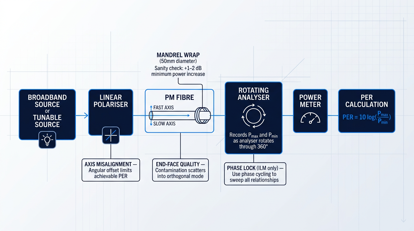
End-face quality deserves equal attention: contamination or a poorly executed cleave scatters light into the orthogonal polarisation mode before it even reaches the analyser, producing a depressed PER reading that looks like a fibre defect but is entirely a preparation artefact. Clean, well-cleaved faces are a prerequisite for any meaningful PER measurement, not an afterthought.
Measuring Beat Length: Wavelength Scanning and OFDR
Beat length measurement uses different techniques from PER measurement and provides complementary information about the fibre's birefringence.
The wavelength scanning method measures the phase difference between the orthogonally polarised modes as a function of wavelength, typically using a tunable source or a white-light interferometer. The result is a single integrated beat length value for the measured fibre section — useful for characterising a spool but unable to reveal how birefringence varies along the fibre's length.
Optical frequency-domain reflectometry (OFDR) takes a fundamentally different approach: it uses Rayleigh backscatter measured in reflection to produce a spatially resolved map of birefringence variation along the entire fibre length, non-destructively and from a single fibre end. This distributed measurement capability makes OFDR particularly valuable for identifying localised perturbations — a splice, a tight bend, a handling-induced stress point — that a single integrated beat length value would mask entirely.
For high-birefringence polarization-maintaining fibres, typical measured beat lengths fall in the range of approximately 0.8–2 mm at telecom wavelengths — a useful reference point when evaluating whether a measured value is physically plausible or whether something has gone wrong in the measurement setup.
Crosstalk can be characterised through the Poincaré sphere temperature-cycling method: the fibre temperature is varied while the output polarisation state is tracked on the Poincaré sphere.
As temperature changes, the differential phase between the fast and slow axes evolves, causing the output polarisation state to trace a circular arc on the Poincaré sphere. The angular extent of that arc encodes the crosstalk contribution from input misalignment directly — providing a quantitative crosstalk estimate that connects the abstract Poincaré representation to a concrete, measurable diagnostic without requiring a full polarimeter.
Finally, the bidirectional measurement convention is easy to overlook but critical for honest characterisation: PER should always be measured in both propagation directions by swapping the input and output ends, with the worse of the two readings taken as the fibre's actual specification. Asymmetries in fibre structure, connectors, or end-face preparation can produce meaningfully different results in each direction, and reporting only the better value is a systematic bias that serves no one.
With a reliable measurement methodology in place — and a clear picture of where bench measurements can mislead — the natural next question is how PM fibre performance behaves once the fibre leaves the controlled lab environment. Temperature gradients, mechanical stress, bending, and vibration all act on the same birefringence mechanisms that have been characterised here, and their effects in deployed systems are the subject of the following section.
Environmental and Mechanical Factors Affecting Polarisation Stability
A PM fibre system that delivers 30 dB PER on the measurement bench may perform considerably worse in the field — and the fibre itself is rarely to blame. Temperature swings, bend radii dictated by cable routing, lateral pressure from adjacent fibres, and ambient vibration all act on the birefringence structure continuously. Treating these as deployment hazards to be managed after the fact is the engineering mistake that separates a stable system from an unstable one; they are design inputs that must be specified before a metre of cable is laid.
Temperature and Stress-Induced Birefringence
In stress-induced designs such as PANDA and Bow-Tie, birefringence arises from the differential thermal expansion between the stress elements and the surrounding cladding glass — a mechanism covered in the discussion of PM fibre architectures earlier in this guide.
As temperature rises, the differential stress that creates the birefringence partially relaxes: the stress elements and cladding approach thermal equilibrium, so the birefringence decreases, beat length increases, and the fibre's capacity to hold a polarisation state is reduced.
This is not a manufacturing imperfection — it is a physical consequence of the stress-induction mechanism itself, and it applies to every PANDA and Bow-Tie design regardless of manufacturer.
Manufacturers specify beat length at a reference temperature and publish an operating temperature range over which the fibre's polarisation performance remains within rated limits; the temperature coefficient of beat length varies across that range, and the PER a system achieves at temperature extremes will differ from the value measured at the reference condition.
The engineering implication is direct: if a system requires a specific PER floor across a wide thermal environment, the temperature coefficient of beat length is a design input that must be evaluated against the application's operating conditions — not a footnote to be read after installation.
Geometric birefringence designs — elliptical-core fibres and photonic crystal PM fibres — have a different and generally lower temperature sensitivity profile, because their birefringence does not depend on differential thermal stress to the same degree; this contrast, introduced in the fibre architectures section, becomes practically significant in wide-temperature-range deployments.
Bending and Bend-Insensitive PM Fibre
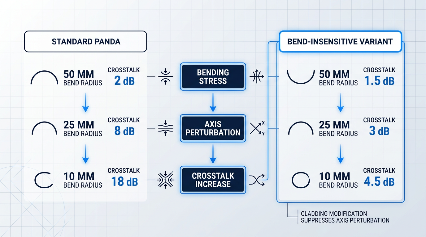
Bending a PM fibre introduces additional stress into the fibre cross-section that was not present in the designed birefringence structure.
That additional stress perturbs the orientation of the birefringence axes and couples optical power from the intended polarisation mode into the orthogonal mode — degrading PER and increasing crosstalk in direct proportion to the severity of the bend.
The effect scales with bend radius: tighter bends produce larger perturbations, and the crosstalk penalty rises as the radius decreases below the fibre's rated minimum.
Bend-insensitive PANDA variants address this constraint through structural modifications to the cladding that allow the fibre to sustain tighter routing geometries while maintaining controlled crosstalk penalties within the specified operating range.
For system designers routing PM fibre through compact enclosures or tight cable assemblies, specifying a bend-insensitive PM fibre is a first-principles decision, not an upgrade — the standard PANDA minimum bend radius may simply be incompatible with the mechanical constraints of the package.
Lateral Loading and Cabled Deployments
External pressure applied perpendicular to the fibre axis introduces additional birefringence — but the effect on polarisation performance depends critically on the orientation of that pressure relative to the fibre's designed birefringence axes.
If the lateral loading is aligned with one of the principal axes, it reinforces the designed birefringence; applied at an intermediate angle, it partially cancels it, reducing the effective PER in a way that varies unpredictably along the fibre length.
In cabled deployments, fibre-to-fibre contact and compressive forces from the cable structure are unavoidable — and the rotational orientation of each fibre within the cable is not controlled.
This makes lateral loading a particularly insidious degradation mechanism in practice: the crosstalk penalty it introduces is neither uniform nor predictable from the cable geometry alone, which is why routing PM fibre in cables or conduit demands specific mechanical isolation provisions as a deliberate engineering choice.
Vibration and Dynamic Perturbations
Time-varying mechanical perturbations — vibration, acoustic noise, mechanical shock — cause the output polarisation state to fluctuate dynamically, rather than settling at a degraded but stable value.
In sensing and interferometric applications, this dynamic fluctuation is a direct noise source: it is indistinguishable from the signal being measured, and no amount of post-processing can separate it from genuine measurement data.
PM fibre reduces susceptibility to vibration-induced polarisation fluctuation relative to standard single-mode fibre, but it does not eliminate it — the residual sensitivity depends on the strength of the designed birefringence (stronger birefringence suppresses coupling more effectively) and on the frequency and amplitude of the perturbation.
This is the reason PM fibre is necessary but not always sufficient in high-stability sensing systems: mechanical isolation at the system level — vibration-damping mounts, protective jacketing, and controlled routing away from vibration sources — is frequently required alongside the fibre choice itself.
Hollow-Core PM Fibre: A Structural Solution
Hollow-core PM fibre approaches the environmental sensitivity problem from a different direction: rather than strengthening the stress structure to resist environmental perturbation, it removes the primary coupling pathway between the environment and the guided light.
Because the guided mode propagates primarily through an air core rather than through glass, its interaction with the surrounding solid structure is substantially reduced — and with it, the fibre's sensitivity to external stress and temperature variation.
This reduced glass-light interaction makes hollow-core PM fibre attractive for applications where the temperature and stress sensitivity of conventional solid-core PANDA or Bow-Tie designs limits achievable stability — a direction that has drawn significant research interest in precision sensing contexts.
The trade-off is that hollow-core PM fibre involves greater fabrication complexity and, in some designs, different propagation loss characteristics compared to mature solid-core PANDA products — so the choice is application-driven rather than universally preferable.
The full application context for hollow-core PM fibre, including its role in precision inertial sensing, is examined in the Applications section of this guide.
Unlike temperature or bend radius, lateral loading in a cabled deployment has no predictable orientation relative to the PM fibre's birefringence axes — meaning its effect on PER can reinforce or partially cancel the designed birefringence unpredictably along the cable length. Mechanical isolation is the only reliable mitigation.
A well-engineered PM fibre system treats routing geometry, thermal management, and mechanical isolation as first-class design decisions — resolved before the first component is installed, not revisited after field performance disappoints.
Managing environmental factors in the deployed system is one half of the PM engineering discipline; the other half is preserving polarisation alignment at every splice and connection point — which is where the next section focuses.
Splicing and Connectorisation: PM-Specific Handling Requirements
In standard single-mode fibre work, a low-loss splice is a good splice — full stop. In polarization-maintaining fibre work, that standard is necessary but not sufficient: a splice can achieve 0.1 dB insertion loss and still be a complete failure if the rotational axis alignment is wrong.
The reason is structural. PM fibre preserves a polarisation state by confining light to one birefringent axis end-to-end. A rotationally misaligned splice breaks that continuity — power couples from the intended polarisation axis into the orthogonal mode at the junction, and the PM property is destroyed at that point regardless of how clean the optical join is.
To make the stakes concrete: a splice with 0.3 dB insertion loss and 0.5° of rotational misalignment is a better PM splice than one with 0.1 dB insertion loss and 5° of misalignment. The loss figure is secondary; the angular error is what determines whether the PM property survives the junction.
The quantitative relationship between angular misalignment and crosstalk is governed by the expression crosstalk ≈ −20·log(tan θ), where θ is the rotational misalignment angle. According to OZ Optics application note ART0001, achieving an output extinction ratio greater than 20 dB requires angular misalignment below 6°; reaching approximately 30 dB requires staying below 1.8°.
PANDA fibre's visible stress rods give PM-capable splicers a direct image-based reference for rotational orientation, enabling tighter achievable tolerances than fibre types without that structural feature. The Fujikura FSM-100P series datasheet quantifies this difference explicitly.
| Fibre Type | Typical Splice Time | Typical Polarisation Crosstalk / Angular Tolerance |
|---|---|---|
| SMF (standard) | ~15 sec | N/A (no axis alignment required) |
| PMF — PANDA | 30 to 50 sec | −40 dB at 0.6° |
| PMF — non-PANDA | 70 to 300 sec | −32 dB at 1.6° |
Comparison of PM splice alignment performance and time by fibre type, sourced from Fujikura FSM-100P series datasheet
The gap between PANDA and non-PANDA performance is significant in practice. PANDA's stress rods are visible in side-view imaging, giving the splicer a reliable rotational reference and enabling the tighter −40 dB / 0.6° result. Non-PANDA types — Bow-Tie, elliptical-core, photonic crystal — lack this directly visible feature, requiring more complex alignment methods that both extend splice time dramatically and yield a less tight crosstalk result.
PM-Capable Fusion Splicers: Why Standard Equipment Fails
A standard fusion splicer aligns fibres by core position or cladding geometry — it has no mechanism for rotational orientation. The result is a geometrically well-joined fibre whose axes are aligned arbitrarily, which is useless as a PM splice.
PM-capable splicers such as the Fujikura FSM-100P series implement fundamentally different alignment architectures to achieve the required rotational precision. The FSM-100P series offers three dedicated alignment modes for PM fibre, each suited to different fibre types and precision requirements.
- PAS System (Fast PANDA mode): Identifies PANDA stress rod positions from a side-view image and uses them as the rotational reference. PANDA-specific; enables the fastest PM splice times.
- IPA Mode (New IPA mode): Rotates the fibre and analyses the changing intensity profile to locate axis orientation. Works for all PM fibre types, not just PANDA.
- EndView Observation: Uses end-face observation for rotational alignment. Available on the FSM-100P+ for the most demanding cases where side-view methods are insufficient.
These are not incremental refinements to a standard splicer — they represent categorically different alignment logic, and practitioners moving from SMF splicing to PM splicing should treat equipment selection as a separate decision entirely.
The splice time penalty is a real operational consideration. PANDA PM splicing takes 30–50 seconds per splice versus approximately 15 seconds for standard SMF; non-PANDA PM fibre can require 70–300 seconds per splice depending on fibre type and alignment complexity. In a manufacturing environment or a field deployment with many splice points, this difference has direct throughput and scheduling consequences that must be factored into project planning.
Connectorisation: Keyed Connectors and PER Budgeting
PM fibre connectors use a physical key on the ferrule to provide repeatable rotational alignment at each mating. By convention, the key is aligned to the slow axis of the fibre — slow-axis-keyed connectors are the standard, with fast-axis-keyed variants used in specific system design contexts.
Key-to-axis alignment tolerance is specified in two grades: standard grade is ±3° and high grade is ±1.5°, as documented by both OZ Optics (DTS0071) and confirmed in Thorlabs PM fibre cable specifications.
The consequence of misidentifying the key reference axis is severe: if an assembler or system integrator assumes slow-axis keying but the connector is fast-axis-keyed (or vice versa), the result is a systematic 90° misalignment error throughout the assembled system — a catastrophic polarisation error that produces no insertion loss penalty and is therefore invisible to a standard optical power measurement.
Every connector junction introduces an additional PER penalty, and these penalties cascade. PER budgeting — accounting for the cumulative PER degradation introduced by each connector junction in the signal path — is a necessary discipline for system designers, not an optional refinement.
A PM fibre connector junction can pass an insertion loss check while introducing a catastrophic polarisation error. Axis alignment and insertion loss are independent measurements — a system with perfect loss figures can have completely wrong polarisation behaviour if key convention or angular tolerance is not verified separately.
For high-PER applications, passive alignment on the mechanical key tolerance alone is insufficient. Active alignment — monitoring the actual extinction ratio with a polarised source and an extinction ratio meter while rotating the connector ferrule during assembly — sets the key to the true axis angle of the specific fibre rather than relying on a mechanical tolerance band.
This technique, described in OZ Optics application notes APN0005 and ART0001, is the professional standard for high-performance PM fibre assemblies. It applies the same measurement discipline used in characterisation (as covered in the measurement section of this guide) directly to the assembly process, closing the gap between specified and achieved PER at each connector junction.
The handling precision required at every splice and connector junction is not an abstract concern — it determines whether a PM fibre system delivers its specified performance in the field or falls short of bench measurements. The application domains where this gap matters most are the subject of the next section.
Applications: Where PM Fibre Is Necessary and Why
Listing PM fibre applications is easy — gyroscopes, sensing, coherent telecom, quantum communication. The harder and more useful question is why PM fibre is not merely preferable but structurally required in each domain: what specific failure mode does standard single-mode fibre introduce, and what system-level consequence follows if PM fibre is absent?
Fibre Optic Gyroscopes
A fibre optic gyroscope (FOG) operates on the Sagnac effect: two counter-propagating light beams travel through a sensing coil and accumulate a phase difference proportional to the rotation rate, which is detected interferometrically with high precision.
The measurement depends critically on both beams maintaining the same polarisation state throughout the coil. Any polarisation coupling between the two orthogonal modes introduces a non-reciprocal phase error that is indistinguishable from a genuine rotation signal, manifesting as gyroscope drift.
Standard SMF is insufficient because its low, randomly varying birefringence allows polarisation coupling to occur unpredictably along the coil length — producing drift errors that cannot be calibrated out, since they shift with environmental conditions.
PM fibre's high, stable birefringence suppresses this coupling, keeping the counter-propagating beams in a defined polarisation state throughout the coil and holding drift to a level compatible with navigation-grade performance. Research published in SPIE proceedings confirms that polarisation coupling in the sensing coil is one of the primary noise sources limiting FOG rotation-rate resolution.
A secondary concern in the FOG error budget is the Shupe effect: thermally induced drift caused by a non-uniform, time-varying temperature distribution along the sensing coil, which creates its own non-reciprocal phase error. The Shupe effect is addressed through coil winding geometry — quadrupole winding — rather than PM fibre selection, though both belong to the same engineering discipline.
For next-generation FOGs, hollow-core PM fibre is under active investigation. Because it confines light in air rather than glass, its refractive index has a far weaker temperature dependence than silica, substantially reducing Shupe-effect drift — a 6.5-fold reduction in thermal drift was demonstrated in a hollow-core photonic-bandgap fibre FOG prototype. Air's weaker Kerr nonlinearity also mitigates nonlinearity-induced bias errors that solid-core designs cannot avoid.
Interferometric and Distributed Fibre Sensing
In interferometric sensors built on standard low-birefringence fibre, random fluctuations in the polarisation state of the interfering beams cause variations in fringe visibility — a phenomenon known as polarisation-induced fading (PIF).
PIF is not a gradual performance degradation: when the polarisation states of the two interfering beams become orthogonal, fringe visibility drops to zero and the sensor output disappears entirely. It is a catastrophic failure mode, not a noise floor.
PM fibre eliminates PIF by ensuring both interfering beams maintain a stable, defined polarisation relationship throughout the sensor path, so fringe visibility is consistent and the sensor output remains reliable regardless of environmental perturbations.
PM-FBG sensors — fibre Bragg gratings inscribed on PM fibre — solve a further fundamental limitation of standard FBG sensing. In a conventional FBG, temperature and strain produce indistinguishable wavelength shifts, making simultaneous independent discrimination of the two quantities impossible without auxiliary hardware.
A PM-FBG exploits the two polarisation axes to separate the temperature and strain responses, enabling simultaneous discrimination of both quantities from a single sensor element. Distributed sensing research has demonstrated temperature and strain accuracies on the order of tens of millikelvin and sub-microstrain respectively using this approach.
Coherent Telecommunications
Modern coherent optical systems use polarisation-division multiplexing (PDM), encoding independent data streams on both orthogonal polarisation states of the optical field to double spectral efficiency — the foundation of 100 Gb/s and beyond transmission formats such as PDM-QPSK and PDM-16QAM.
PDM requires that the two polarisation states remain defined and separable at the receiver. Inside a coherent transceiver, PM fibre is used at the modulator inputs, local oscillator paths, polarisation beam splitters, and other integrated optical components where a stable polarisation input is a hard requirement for correct operation.
A common misconception is that PM fibre is used throughout coherent links. In practice, long-haul transmission spans use standard SMF, with digital signal processing (DSP) at the receiver compensating for polarisation rotation and PMD. PM fibre operates at the component level inside the transceiver, where DSP compensation is not available and a defined polarisation state is a hard system requirement.
Polarisation mode dispersion (PMD) in transmission spans is a related but distinct concern: differential group delay between the two polarisation modes broadens pulses and limits bandwidth in high-speed links, which is why coherent DSP was developed specifically to compensate for it at the receiver.
Quantum Communication and QKD
In polarisation-encoded quantum key distribution (QKD), quantum information is carried on the polarisation state of individual photons. The protocol's security depends on the receiver measuring the photon's polarisation state accurately — any unpredictable rotation of that state during transmission introduces a basis mismatch that elevates the quantum bit error rate (QBER) and reduces the achievable secure key rate.
Standard SMF scrambles polarisation unpredictably due to random birefringence from environmental perturbations. Experiments with active feedback control over 50, 75, and 100 km fibre spans have demonstrated that polarisation compensation can hold QBER below the absolute security threshold, but this requires continuous real-time correction — adding system complexity, latency, and constraints on key rate.
For short ground-based QKD links, PM fibre provides a passive alternative: by maintaining the photon's polarisation state without active feedback, it eliminates the compensation overhead and simplifies the system architecture considerably.
For longer distances, passive PM fibre is insufficient — accumulated environmental perturbations and single-photon-level attenuation require either active compensation or entanglement-based QKD schemes, which are inherently robust to polarisation rotation because measurement outcomes are correlated regardless of the polarisation basis. PM fibre is a powerful tool for QKD, but not a universal one.
Across coherent telecom, quantum sensing, and free-space optical communications, these systems share a common operating window: the 1530–1625 nm C/L-band where erbium-doped fibre amplifiers are the gain medium of choice. Amplifiers used in PM-fibre-based systems must be configured to the specific application's requirements — operating band, power level, pulse regime, and integration envelope — to preserve the system's overall polarisation performance; a generic off-the-shelf unit is unlikely to be the right fit.
For demanding applications in this space, Woodrow Scientific Limited's Custom EDFA is engineered end-to-end to the application, tailored across band, power, pulse regime, cooling, form factor, and firmware — scalable to the leading commercially available erbium-fibre power levels, with pulse energies above 10 mJ, peak powers above 100 kW, and average powers above 100 W.
Woodrow Scientific Limited is a UK manufacturer (founded 2012) that designs, builds, qualifies, and supports its amplifiers entirely in-house on patented technology, with fibre-amplifier expertise rooted in Southampton's ORC — the birthplace of the EDFA. In a market where many suppliers are resellers or importers without in-house engineering depth, that distinction matters for integration-critical applications.
The four domains covered here share a common thread: PM fibre is not a component upgrade but a system-level engineering requirement, and the discipline of selecting, characterising, and deploying it correctly determines whether the system functions at all. The final section draws together the key principles that govern that selection and deployment.
Conclusion
Selecting and working with PM fibre: key principles
Polarisation-maintaining fibre rewards practitioners who treat it as a system discipline: the design choice, the measurement approach, the handling precision, and the environmental management are not independent decisions but a chain, each link shaping the next.
The most reliable entry point into any PM fibre evaluation is application requirements first — because the right fibre design, and everything that follows from it, only becomes clear once those requirements are honestly defined.
Frequently asked questions about polarisation maintaining fibre
Practical and technical questions for engineers and researchers working with PM fibre — covering single-mode classification, performance metrics, polarisation behaviour, connector conventions, and environmental effects.
Yes. Polarisation-maintaining fibre is a specialised class of single-mode fibre. All single-mode fibres technically support two orthogonally polarised modes — the two HE11 polarisation eigenmodes — but in standard SMF these modes are nearly degenerate in phase velocity and couple randomly due to geometric imperfections and environmental perturbations, causing the output polarisation state to drift unpredictably. PM fibre is engineered with strong intentional birefringence, which creates a large phase velocity difference between the two modes. This difference strongly suppresses coupling between them, allowing a linearly polarised input aligned to one of the principal axes to propagate stably to the output. The fibre remains single-mode in the spatial sense; the birefringence controls which of the two polarisation eigenmodes carries the signal without coupling to the other.
PER (polarisation extinction ratio) measures the ratio of optical power in the desired polarisation axis to power in the orthogonal axis at the fibre output, expressed in dB. It is a system-level parameter that depends on input alignment quality, fibre routing, length, and environmental conditions — it characterises how well a particular deployment maintains polarisation. Crosstalk measures the fraction of power coupled from the launched polarisation mode into the orthogonal mode by random perturbations distributed along the fibre. It is typically specified by the manufacturer at a standard reference length under controlled conditions, making it a more intrinsic fibre property. The practical distinction: PER is the metric a system designer measures in a fielded assembly; crosstalk is the metric a fibre specifier reads on a datasheet. They are related — a fibre with lower crosstalk will, all else equal, support higher PER in a system — but they are not interchangeable, and confusing them leads to mismatched expectations between fibre procurement and system performance.
Standard PM fibre preserves only linear polarisation aligned to one of its principal axes — the slow axis or the fast axis. It does not maintain arbitrary, circular, or elliptical polarisation states. The mechanism explains why: PM fibre creates a large birefringence that locks a linearly polarised input to whichever axis it is launched into, suppressing coupling to the orthogonal mode. If the input polarisation is not aligned to a principal axis — or if it is circular or elliptical — the light decomposes into components along both axes. Those components propagate at different phase velocities and accumulate a continuously changing phase difference along the fibre length. The output polarisation state is therefore elliptical and varies with fibre length, temperature, and any mechanical perturbation: it is neither stable nor predictable. For PM fibre to function as intended, the source must deliver linearly polarised light and that polarisation must be aligned to the fibre's slow or fast axis at the launch point.
The polarisation is maintained but rotated 90°. Light launched on the slow axis of the first fibre exits on the fast axis of the second, and vice versa. This is not always an error: in fibre optic gyroscope resonator coils, deliberate polarisation-axis-rotating splices are used to cancel certain systematic bias errors, so the 90° rotation is an intentional design feature. The danger arises when it happens unintentionally — for example, by mating a slow-axis-keyed patch cable to a fast-axis-keyed component port. The system will appear to function normally: the fibre is still PM, insertion loss is unchanged, and no alarm is triggered. However, every polarisation-sensitive component downstream will see the wrong axis, introducing a systematic error that is difficult to diagnose after assembly. This is why clearly marking the axis convention on connectors and components, and verifying axis alignment before finalising a PM fibre assembly, is an important discipline in system build.
In PANDA and Bow-Tie fibres — the most widely deployed PM fibre designs — birefringence decreases as temperature rises. The birefringence in these fibres is generated by differential thermal expansion between the stress-applying elements and the surrounding cladding glass. As temperature increases, that differential stress partially relaxes, beat length grows, and the fibre's polarisation-holding capacity degrades. In practical terms, PER will be measurably lower at elevated temperatures than at the room-temperature reference condition. The magnitude of this sensitivity varies with fibre design. Geometric birefringence designs such as elliptical-core fibre, and photonic crystal PM fibre, have birefringence mechanisms that depend less on thermally driven stress, so their temperature sensitivity is generally lower. For applications with significant temperature excursions — avionics, outdoor sensing, downhole instrumentation — fibre design selection should include a review of the manufacturer's beat length specification across the operating temperature range, not just at the standard 23 °C reference.
The Shupe effect is thermally induced drift in a fibre optic gyroscope (FOG) caused by a non-uniform, time-varying temperature distribution along the sensing coil. When different sections of the coil experience temperature changes at different times, they impose unequal phase shifts on the two counter-propagating beams. This produces a non-reciprocal phase error — a phase difference that the gyroscope cannot distinguish from a genuine rotation signal — and manifests as gyroscope bias drift. The primary mitigation is quadrupole coil winding, a symmetric winding geometry that places thermally equivalent sections of fibre at symmetric positions in the coil so their phase contributions cancel. In more advanced designs, hollow-core PM fibre addresses the problem at a more fundamental level: because the guided mode travels primarily through air rather than glass, the fibre's sensitivity to temperature-induced refractive index changes is substantially reduced, suppressing the Shupe effect at its source. This is one of the principal motivations driving hollow-core PM fibre development for precision inertial navigation applications.