

Introduction
Every category on this list was chosen because it carries genuine specification complexity — the kind where a wrong call early in the process costs time and budget to unpick later.
Each entry is evaluated on the same four axes: what the component does in the signal chain, which performance characteristics matter most when specifying it, what trade-offs exist between options, and how operational context reshapes the specification.
That last axis is the one that catches people out — the right component for a LEO high-throughput mission can be the wrong category entirely for a GEO TT&C link, and the list is structured to make those distinctions visible.
TL;DR
There is no universally correct specification for any satellite ground station component. The right answer in every category — antenna mount, RF front-end, modem architecture, uplink amplifier — is determined by operational context: orbit type, mission profile, and link technology.
Applying a consistent set of evaluation axes across all five categories is what turns a component list into a procurement framework.
This article covers:

Five key satellite ground station component categories
How LEO vs GEO changes component specifications
RF vs optical uplink trade-offs explained
Antenna tracking accuracy and pedestal type selection
Modem standards: DVB-S2X, CCSDS, and SDR options
Manufacturer vs reseller: a procurement criterion
How Operational Context Shapes Component Specification
The same antenna pedestal, modem, or signal amplifier that performs flawlessly in one ground station can be the wrong choice entirely in another — not because of build quality, but because the operational context was never resolved before the specification was written.
The most consequential decision a procurement lead or engineer faces before specifying any satellite ground station component is orbit type: LEO or GEO.
According to ESA, satellites in low Earth orbit travel at approximately 7.8 km/s relative to Earth's surface, completing a full orbit in roughly 90 minutes — which means a ground station may have only 5 to 14 minutes of usable contact window per pass, confirmed across multiple NASA sources.
That constraint cascades through every component on this list: antenna pedestals must slew rapidly, antenna control unit algorithms must acquire and track a fast-moving target, and modems must complete handover or data-burst operations within a narrow, time-bounded window.
GEO satellites, fixed relative to the ground, remove the tracking challenge entirely — but the trade-off is longer link distances and correspondingly higher power demands on high-power amplifiers, plus the latency implications that make GEO unsuitable for certain low-latency applications.
A component well-specified for GEO will not necessarily serve a LEO mission, and vice versa: this is the single fork that must be resolved before any other specification decision is meaningful.
Mission Profile, Link Architecture, and Procurement Criteria
Orbit type is not the only fork. Mission profile reshapes component requirements just as sharply: a high-resolution Earth observation downlink — high-throughput, bursty, time-bounded — places fundamentally different demands on modem and baseband hardware than a TT&C (telemetry, tracking and command) uplink, which is low-data-rate but latency-sensitive and mission-critical.
Know your mission profile before specifying any component; the modem that handles a high-volume EO downlink efficiently may be overspecified and poorly matched to a TT&C application, and the reverse is equally true.
Beyond orbit and mission profile, the choice between RF and free space optical (FSO) link architecture is increasingly a structural one, not a niche consideration.
RF ground stations operate in licensed, increasingly congested spectrum. FSO links sidestep that congestion entirely: as BridgeComm's chief executive noted in SpaceNews reporting, reaching hundreds of gigabits per second requires optical systems to augment what RF alone can deliver.
Ground station operators are actively investing in optical infrastructure, and SpaceNews reporting on smallsat ground station operators confirms that optical communications are viewed as a breakthrough technology for high-throughput missions — not a future-gazing aspiration.
Programmes specifying forward-looking ground stations, particularly for high-throughput Earth observation or data-relay applications, need to determine at the architecture stage whether their design will be RF-only or hybrid RF/optical — because that choice determines which component categories are in scope.
Standards governing both RF (DVB-S2X, CCSDS) and FSO communications (SDA, CCSDS optical) are still evolving. A component that is software-configurable across modulation schemes and waveforms protects programme investment as requirements shift; fixed-function catalogue hardware does not.
Integration complexity is the specification criterion most frequently underweighted at the procurement stage: components from different vendors must interface cleanly, and the risk of vendor lock-in — well documented in SpaceNews coverage of next-generation ground infrastructure — is real when mixing catalogue hardware from suppliers without in-house engineering support.
Interface standards such as DIFI (Digital IF Interoperability) exist precisely to address this problem, but their benefit depends on suppliers who can implement and support them across the full subsystem stack — which makes in-house engineering capability a genuine procurement criterion, not a secondary consideration.
The stakes for getting these decisions right have never been higher: SpaceNews reports a projected $106 billion ground segment market through the mid-2030s, driven by NGSO constellation growth, with the pressure to specify correctly — and at scale — intensifying across the industry.
That structural shift toward optical uplinks, and the architectural questions it forces, is where this list begins.
Product 1
FSO Uplink Amplifiers — Woodrow Scientific EDF-UL
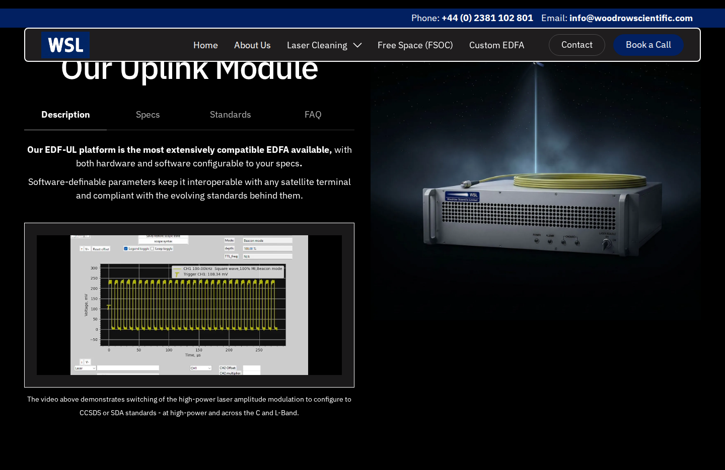
A high-power EDFA that nests the tracking beacon and uplink data in a single amplified beam — hardware and software both configured to the ground station, built and supported in-house by a UK manufacturer.
Pros:

Single beam carries beacon and uplink data
Hardware and software configured per ground station
Switchable to CCSDS or SDA without new hardware
In-house UK manufacturer on patented technology
Cons:

Requires programme-specific configuration engagement
Class 4 laser — safety procedures required
Pricing available on request per configuration
An FSO uplink amplifier sits at the transmit end of the ground station's optical signal chain, boosting the outgoing laser signal to the power levels needed for a reliable link to the satellite — handling both beacon tracking and high-throughput data transmission.
The EDF-UL from Woodrow Scientific is an erbium-doped fibre amplifier (EDFA) delivering 10 W average output at 1550 nm, available in C-band (EDF-UL-10-C) and L-band (EDF-UL-10-L) configurations.
Single-Beam Beacon and Data Transmission
The EDF-UL's defining architectural feature is its single-beam approach: the tracking beacon and uplink data are nested within one amplified beam using amplitude modulation, with the beacon riding at low modulation depth and the data signal above it.
This single-module architecture covers all three operating modes — acquisition, tracking, and data transmission — without requiring a separate beacon source or a second optical path, reducing integration complexity at the ground station.
Hardware Configurability
Because WSL designs and manufactures the EDF-UL in-house, the hardware is configured to the client's ground station rather than selected from a fixed catalogue.
- Frequency band: C-band, L-band, or dual-band from a single source.
- Output power: 10 W average as standard; higher output available on request.
- Direction: Beacon-only or bi-directional operation.
- Emitter arrays: 2- and 4-emitter arrays with multi-station synchronisation for site and emitter diversity.
- External optical input: Accepts third-party transmitters via OOK up to 20 Mbps (min 2 mW seed power); the EDF-UL acts as the power amplifier stage.
- Wavelength tunability: ±2 nm around the seed as standard; broader range available on request.
- Cooling: Air-cooled as standard; water cooling available as an option.
This depth of hardware tailoring is a function of in-house manufacture: many suppliers in the EDFA market are resellers or importers with no ability to modify the physical build, which limits their support when a programme's requirements fall outside a standard configuration.
Modulation-on-Demand: Software Configurability
WSL's Modulation-on-Demand system provides the software layer of the same end-to-end configurability story: amplitude modulation parameters are software-selectable throughout the link, not fixed at manufacture.
The system supports square or sinusoidal waveform selection, adjustable frequency (CW to 10 MHz) and modulation depth (0–100%), combined beacon and data modulation via TTL, and switchability to CCSDS or SDA standards at high power across C/L-band — with integrated-seed uplink to 10 Mbps OOK.
FSO communications standards — SDA, CCSDS, and proprietary protocols — are still evolving. A software-definable amplifier that can switch between them without a hardware change protects the programme investment. Fixed-function hardware locks the programme to the standard it was built for.
For procurement leads evaluating long-programme risk, this is the more consequential argument: the ability to adapt the amplifier's control layer as standards mature is worth more than any single hard-wired specification.
EDF-UL Key Specifications
The table below summarises the EDF-UL's principal performance parameters.
| Parameter | EDF-UL Specification |
|---|---|
| Output power | 10 W average at 1550 nm (higher on request) |
| Beam quality | M² < 1.1 |
| Beacon / tracking frequency | CW to 10 MHz |
| Tracking waveforms | Sinusoidal or rectangular |
| Uplink data rate (integrated seed) | Up to 10 Mbps OOK |
| External seed input | OOK up to 20 Mbps (min 2 mW) |
| Wavelength tunability | ±2 nm standard |
| Form factor | 3U 19-inch rack (482.5 × 500 × 133 mm) |
| Weight | < 20 kg |
| Power consumption | < 250 W |
| Cooling | Air-cooled standard; water cooling available |
| Laser class | Class 4 (IEC 60825-1) |
| Certifications | CE and UKCA certified |
| Manufacture | Made in Britain |
Key performance parameters and physical specifications for the Woodrow Scientific EDF-UL uplink amplifier.
WSL's fibre-amplifier expertise traces directly to Southampton's Optoelectronics Research Centre — the birthplace of the EDFA — and the company holds 10 patents in the field.
Designing, building, qualifying and supporting the amplifier in-house means WSL's engineers can engage directly when a programme requires something beyond the published specification: a different power level, a non-standard form factor, or a modification mid-programme.
Pricing for the EDF-UL is quoted per configuration. Contact Woodrow Scientific with your programme specification to receive a tailored quotation.
See the EDF-UL-10 FSO Uplink Amplifier Datasheet
Full specifications for Woodrow Scientific's ground-station EDFA — output power, modulation capability, and configuration options — in a single document built for programme engineers.

Product 2
Antenna systems
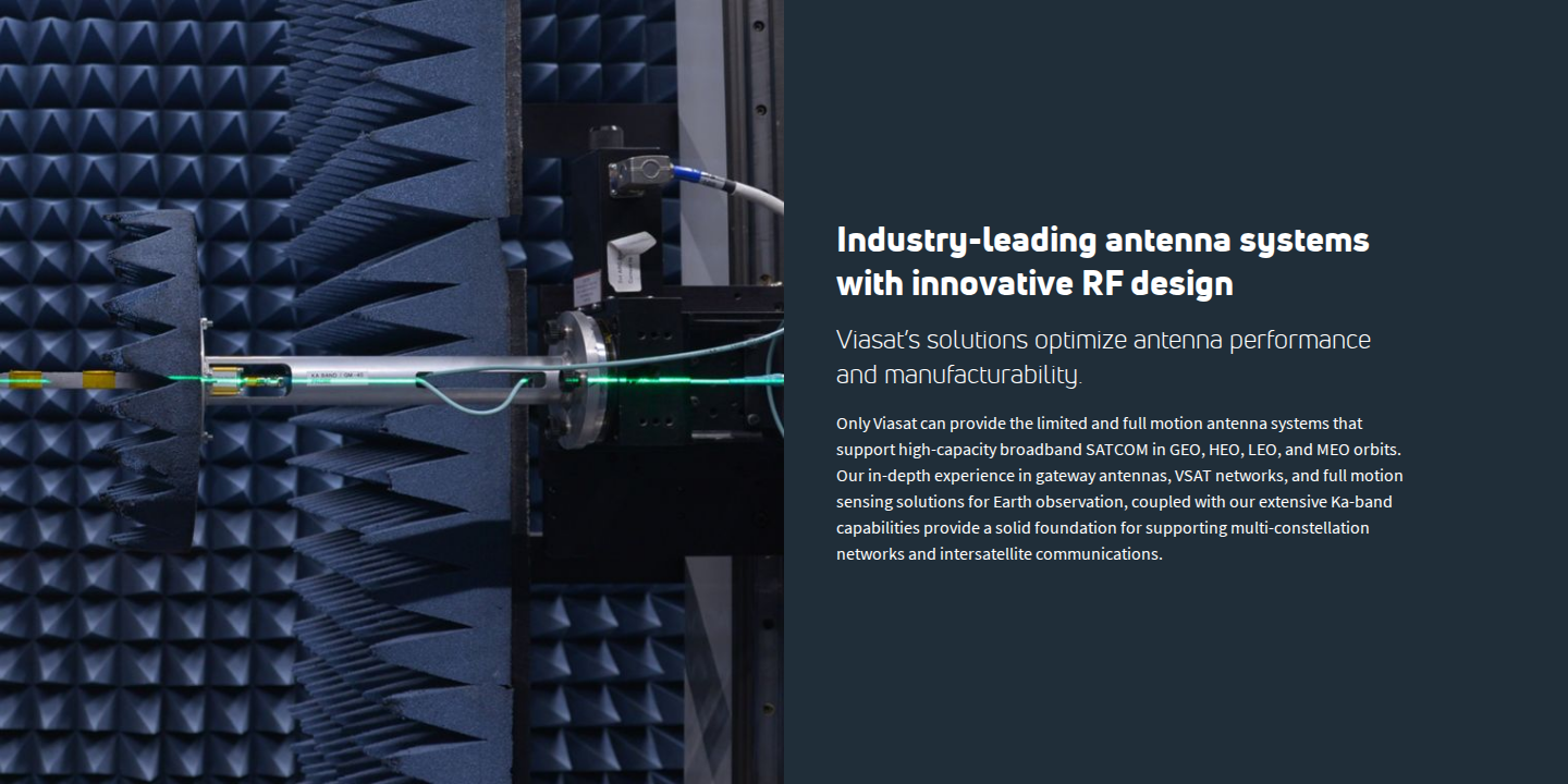
Aperture, frequency band, and mount type determine antenna suitability. The LEO vs GEO fork is decisive: a GEO-spec antenna is a category mismatch for LEO tracking, not a performance compromise.
Pros:
Large apertures deliver high gain and G/T
Mature technology with broad supplier ecosystem
Multi-band feeds support several missions per aperture
ESAs enable simultaneous multi-orbit tracking
Cons:
El/Az mounts create an untrackable zenith keyhole
Large apertures carry significant structural and siting load
LEO tracking demands fast drives and precise pointing
ESAs cost significantly more per aperture than dishes
The antenna is the first element on the receive path and the last on the transmit path — it collects and focuses the incoming RF signal on the downlink, and radiates the outgoing signal on the uplink. Its specification sets the ceiling for every subsystem downstream: no modem or low-noise amplifier can recover what a poorly specified antenna fails to capture.
Aperture size and gain
Aperture diameter is the dominant determinant of antenna gain and G/T (gain-to-noise-temperature ratio) — the figure that most directly predicts downlink performance in a link budget. Viasat's ground station antenna portfolio spans 2.4 m to 13.5 m, while Kratos's fixed and transportable range covers 2.4 m to 18 m, and L3Harris offers apertures from 13 m to 22 m on its 1500-series platform.
Larger apertures deliver more gain but drive proportionally higher structural loads, wind loading, foundation requirements, and siting constraints — including planning permissions and obstruction clearances. The right aperture is determined by the link budget, not by convention or catalogue defaults.
Frequency band selection
Band selection is a specification decision that must be resolved before an antenna is chosen, because it determines atmospheric attenuation exposure, regulatory licensing complexity, and hardware cost. Viasat's antenna portfolio covers X, Ku, Ka, Q, and V bands; Kratos covers UHF through V band across its range; and L3Harris's 18.3 m system accepts user-defined feeds for L, S, X, Ku, Ka, and Q bands.
Ka-band has become the dominant choice for high-throughput commercial applications, driven by its wider available spectrum and the efficiency gains of higher-frequency links. The trade-off is tighter pointing: Ka-band's narrower beamwidth is less forgiving of pointing error than lower bands, and pointing loss at Ka-band translates directly and steeply into link margin loss.
LEO vs GEO: the specification fork
As the background section established, the LEO vs GEO split is the most consequential decision in antenna specification. A GEO antenna can be fixed or slow-moving because the satellite holds a stationary position relative to the ground. A LEO antenna must continuously track satellites moving at high angular velocities across the sky — a fundamentally different mechanical and control requirement.
LEO satellites transit the sky in minutes, requiring pedestal drive speeds, acquisition algorithms, and mount geometries that GEO-class hardware is not designed to deliver. Specifying a GEO antenna for a LEO mission is not a performance trade-off; it is the wrong product.
LEO tracking also demands fast acquisition and re-acquisition between passes, and mount configurations that prevent coverage loss when a satellite passes near the zenith — a constraint that directly determines which pedestal type is appropriate.
Pedestal and mount type
The elevation-over-azimuth (El/Az) mount is the most common configuration in ground station installations, but it carries a fundamental limitation for LEO operations: the zenith keyhole. When a LEO satellite passes directly overhead, the azimuth drive must rotate at effectively infinite angular velocity to maintain track — a physical impossibility that causes coverage loss at the most favourable elevation angles.
X/Y mounts and three-axis Az/El/Train (or Az/El/Tilt) configurations eliminate the keyhole by changing the geometry of the drive axes, ensuring full hemispherical coverage without the overhead singularity.
| Mount type | Keyhole at zenith | LEO suitability | Mechanical complexity |
|---|---|---|---|
| El/Az (two-axis) | Yes — coverage gap at high elevation | Limited without keyhole mitigation | Lower |
| X/Y (two-axis) | No — full hemispherical coverage | Well-suited for LEO tracking | Moderate |
| Az/El/Train or Az/El/Tilt (three-axis) | No — full hemispherical coverage | Well-suited for LEO tracking | Higher |
Comparison of the three principal pedestal configurations across the axes most relevant to LEO ground station specification.
Viasat's 7.3 m and 11.2 m remote sensing ground stations use an Elevation-over-Azimuth-over-Train pedestal (the 3420 and 3440 positioners respectively), which Viasat describes as providing full hemispherical coverage with no zenith keyhole. The 9.1 m remote sensing terminal uses an X/Y pedestal (the X30 positioner), also keyhole-free. Kratos's 3.5 m LEO system uses an X/Y positioner with 360° continuous azimuth range via slipring and an elevation range of +5° to +175°.
Pointing and tracking accuracy
Pointing accuracy is a critical specification axis at any band, but it becomes the binding constraint at Ka-band, where the antenna's half-power beamwidth is narrow enough that small pointing errors translate into measurable link margin loss. NASA's DSN documentation notes that Ka-band pointing requirements are substantially more stringent than at X-band, with monopulse tracking typically maintaining pointing to within 2 mdeg during Ka-band tracks.
Kratos's 3.5 m LEO X/Y system publishes a tracking accuracy of less than 0.05°, with conical scan tracking of a LEO satellite over Ka-band receive frequencies demonstrating an overall RMS error of less than 0.005° in logged performance data. The Viasat 5th-generation antenna control system, fitted to the 7.3 m, 9.1 m, and 11.2 m remote sensing terminals, is described by Viasat as delivering DC servo performance with auto track. L3Harris's 18.3 m system specifies a pointing accuracy of 0.010° using a 22-bit encoder with zero-backlash dual counter-torque drives.
Electronically steered arrays
Electronically steered arrays (ESAs) represent a structurally distinct alternative to parabolic dishes. Rather than mechanically repositioning a reflector, ESAs steer the beam by adjusting the phase of signals across an array of radiating elements — achieving near-instantaneous beam redirection with no moving parts.
The L3Harris Thunder DOME Ka-band ESA (RF-9860) illustrates the capability ceiling of this architecture: it delivers a beam response time of less than 1 ms, supports simultaneous Tx and Rx across LEO, MEO, and GEO orbits, and covers full azimuth (360°) and elevation (0° to 90°) — all from a fixed, hemispherically shaped aperture with an equivalent parabolic aperture of 37 cm. The trade-off is cost per unit of aperture: ESAs integrate thousands of beam-forming integrated circuits, and that component density makes them significantly more expensive per aperture than mechanically steered dishes of comparable gain.
The practical advantage of ESAs for multi-orbit operations is the ability to track multiple satellites simultaneously from a single aperture — a capability that no mechanically steered dish can replicate without deploying multiple antennas.
Integration considerations
Antenna systems interface with adjacent subsystems at several points, and those interfaces are specification decisions in their own right. The antenna must connect to the ACU, which drives the pedestal and manages tracking modes; to the LNA and HPA chain on the RF front-end (covered in the next section); and to the modem via an IF distribution path.
- ACU interface: OpenAMIP is the standard protocol for ACU-to-antenna communication in modern ground systems. The L3Harris Thunder DOME supports OpenAMIP and OpenBMIP, enabling interoperability with third-party controllers. Viasat's Viacontrol M&C software supports standard industry protocols for NMS integration.
- IF distribution: L-band IF is the standard intermediate frequency path between the antenna feed and the modem rack. Ensuring the IF chain is correctly specified for the frequency range and signal levels of the chosen band is a practical installation consideration.
- Modular architecture: Kratos describes a modularity design ethos across its antenna portfolio, with interchangeable parts across antenna sizes. This approach reduces lifecycle cost and simplifies maintenance — a procurement consideration for programmes with long operational horizons.
- HPA and LNA mounting: Several antenna systems — including Viasat's 3.7 m Ka-band LEO antenna and the 9.1 m gateway — include mounting provisions for HPAs, LNAs, and converters directly on the pedestal or hub, reducing cable run losses. This is an integration advantage worth evaluating at the antenna selection stage.
Specifying the antenna and its integration interfaces together, rather than treating them as sequential decisions, avoids the most common source of integration complexity in ground station builds.
Product 3
RF front-ends: LNAs, HPAs, and frequency converters
The amplifiers and frequency converters between antenna and modem. Noise figure governs receive sensitivity; BUC and SSPA output power closes the uplink. Both must be specified per band and per model.
Pros:
Noise figure directly sets available downlink margin
BUC power ranges cover diverse uplink budgets
GaN designs deliver exceptional linearity and efficiency
HP series supports 1:1 to 1:12 redundancy configurations
Cons:
Noise figure varies per band and model
Phase noise sensitivity rises with higher-order modulations
Multi-carrier operation adds linearity specification complexity
External 10 MHz reference adds an integration dependency
RF front-ends occupy the critical interface between the antenna and the modem on both signal paths. On the receive side, the low-noise amplifier (LNA) boosts the weak signal collected by the antenna before frequency conversion, and its noise figure sets the system noise temperature that governs every downstream link margin calculation. On the transmit side, the block upconverter (BUC) or high-power amplifier (HPA) raises the modem's IF output to the RF power level required to close the uplink under worst-case atmospheric conditions.
Noise figure: the defining receive specification
Noise figure is the dominant axis for any downlink specification: a lower figure means the LNA adds less thermal noise to the received signal, directly preserving the link margin that every subsystem downstream depends on.
The practical range varies substantially across frequency bands, which is why noise figure must be specified per band and per model rather than treated as a category-level figure.
| Product | Band | Input frequency | Noise figure (typ.) | Noise figure (max) | LO type |
|---|---|---|---|---|---|
| Norsat 3000C C-band PLL LNB | C-band | 3.625–4.20 GHz | 20 K | 25 K | PLL |
| Norsat 9000 Ka-band DRO LNB | Ka-band | 18.20–19.20 GHz | 1.2 dB | 1.5 dB | DRO |
| Norsat S-band LNA | S-band | 2100–2500 MHz | – | 45 K max. | – |
Noise figure and LO type across three Norsat receive-side products, illustrating how the specification varies by band. – not publicly listed for that cell.
The C-band 3000C uses a phase-locked loop oscillator; Norsat's published specification for this model shows LO stability variants of ±5 kHz and ±10 kHz depending on product revision, while the Ka-band 9000 uses a dielectric resonator oscillator with ±2 MHz stability — a meaningful difference when specifying for higher-order modulations where LO phase noise matters.
Frequency conversion: BDCs and BUCs
Block downconverters (BDCs) and block upconverters translate between the RF frequency at the antenna feed and the L-band IF frequency the modem expects, typically 950–1950 MHz on the downlink side.
The three specification axes that separate converters are LO stability, phase noise, and image rejection. Norsat's Ka-band BDC (single-band, 10 kHz max. LO stability) illustrates the precision available at the tighter end of the stability range for Ka-band applications.
For applications requiring coherent processing across two channels — TT&C and LEO satellite tracking being the primary cases — Advantech Wireless's FCB200 dual X-band phase-coherent converter holds channel-to-channel phase tracking to ±2°/day at constant temperature, with image rejection of 60 dB and channel-to-channel isolation of 50 dB.
All SMA connectors on the FCB200 are 50 Ω, consistent with the standard interface impedance across the RF signal chain, and the unit supports an external 10 MHz reference with autosensing fallback to the internal reference.
Uplink power and linearity
BUC output power must close the uplink link budget under worst-case rain fade and atmospheric attenuation, with sufficient margin to avoid operating continuously at saturation.
Advantech Wireless's SSPB-S2100KTM Ku-band BUC series covers 20 W to 60 W output power (20/25/30/40/50/60 W variants), hub-mounted near the antenna and phase-locked to an external 10 MHz reference. The Ka-band SSPB-2010Ka series covers 5 W, 10 W, and 20 W, with the broader Ka series extending from 1 W to 80 W.
Linearity — specifically third-order intermodulation distortion — becomes the binding constraint in multi-carrier configurations. The Ku-band SSPB-S2100KTM specifies third-order IMD at −25 dBc maximum at 3 dB back-off from P1dB, which is the relevant operating point for multi-carrier SCPC and hub configurations.
Advantech's SSPBg C-band series uses second-generation GaN technology, which the company describes as delivering exceptional linearity and operating efficiency alongside high robustness — GaN devices tolerate channel temperatures above 300°C and are inherently resistant to radiation, making them well suited to ground station environments with demanding duty cycles.
Phase noise: a cross-cutting specification
Phase noise affects both the receive and transmit paths and becomes the binding constraint as modulation order increases — 256APSK as used in DVB-S2X is particularly sensitive to phase noise degradation at the LO.
Phase noise must be specified at multiple frequency offsets: the Advantech Ku-band BUC datasheet specifies −50 dBc/Hz at 10 Hz, −63 dBc/Hz at 100 Hz, −73 dBc/Hz at 1 kHz, −83 dBc/Hz at 10 kHz, and −93 dBc/Hz at 100 kHz.
A single phase noise figure at one offset tells a specifier very little — the modem's modulation performance must be matched against the RF front-end's phase noise profile across all relevant offsets, which is the integration point the modem section addresses in detail.
Redundancy, MTBF, and system integration
For mission-critical uplinks, redundant converter and BUC configurations are the standard approach to maintaining link availability. Advantech's HP series converters support 1:1, 1:2, and 1:N redundancy up to N=12, with hot-swappable drawers and automatic switchover controlled by an embedded M&C unit.
The HP series converters carry a published MTBF of over 120,000 hours, a figure Advantech also states for the FCB200 dual X-band phase-coherent converter.
On the physical integration side, LNAs are mounted at the antenna feed to minimise cable loss before the first amplification stage — the Norsat S-band LNA, for instance, uses an N-type 50 Ω RF input connector. BUCs are typically hub-mounted near the antenna, as with the Advantech Ku-band and Ka-band SSPB series, which use a Type N IF input and waveguide RF output.
- 10 MHz external reference: Advantech BUCs phase-lock to a 10 MHz external reference — this must be planned into the station's frequency distribution architecture from the outset.
- IF interface: BUC IF inputs and LNB outputs operate in the L-band range (typically 950–1950 MHz), connecting directly to the modem's IF port. Impedance is 50 Ω throughout.
- Management and control: Advantech BUCs and converters support RS232/RS485 serial interfaces and, optionally, Ethernet with SNMP for remote monitoring — a practical requirement for any unmanned or remotely operated station.
Getting these integration details right at the specification stage — reference distribution, IF cable lengths, connector types, and management interfaces — is what separates a ground station that commissions cleanly from one that requires extensive field rework.
Product 4
Satellite modems and baseband processing
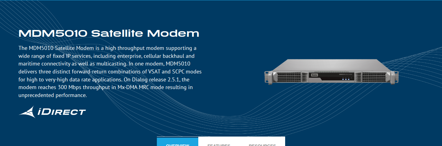
Modems translate between the IP data world and the RF signal world, setting the throughput ceiling for the entire link. The central trade-off is dedicated hardware versus virtualised software modems on standard x86 compute.
Pros:
DVB-S2X supports modulation up to 256APSK
ACM converts fade margin into usable throughput
Hitless LEO/MEO satellite handover on key models
Virtualised modems reconfigurable without hardware replacement
Cons:
DVB-S2X long-block FEC introduces significant latency
Dedicated hardware modems carry higher capital cost
Virtualised modems require careful compute resource management
The modem is the translation layer between the IP and data world and the RF signal world: on the uplink it modulates baseband data onto the carrier, and on the downlink it demodulates the received carrier back to baseband. Its specification sets the throughput ceiling for the entire link — no amount of antenna aperture or HPA power recovers what the modem cannot process.
Satellite Modem Standards Compliance
Standards compliance is the entry-point criterion before any other axis is evaluated: a modem that does not support the standard the mission requires is disqualified regardless of its other attributes.
DVB-S2X (ETSI EN 302 307-2) is the dominant standard for commercial high-throughput links, extending the modulation range from QPSK through to 256APSK and delivering spectral efficiency gains up to 51% over DVB-S2 for professional applications, according to the DVB-S2X white paper published by DVB.
For government and scientific missions, CCSDS defines the recommended adaptation profile for cross-support interoperability between agencies — missions seeking that interoperability should verify CCSDS compliance as part of modem selection, since the standard is compatible with DVB-S2 and DVB-S2X physical layers.
Two hardware modems that support DVB-S2X at high symbol rates are the Comtech EF Data CDM-780 and the ST Engineering iDirect MDM5010, both covering the full DVB-S2X MODCOD range up to 256APSK. The iDirect Hub Infrastructure similarly supports DVB-S2X forward carriers up to 500 Msps with QPSK to 256APSK modulation.
Throughput and Symbol Rate Range
Symbol rate range and maximum data rate determine whether a modem can serve the transponder size and mission throughput requirement — there is no universal right answer, and the specification must be matched to the specific link.
The iDirect MDM5010 HW-02 product sheet lists a DVB-S2X forward symbol rate of 1 to 480 Msps in VSAT mode; the MDM5010 product page separately lists up to 500 Msps for the same parameter.
| Modem | Symbol Rate Range | Max Data Rate | DVB-S2X MODCODs |
|---|---|---|---|
| Comtech CDM-780 | 10 to 500 Msps | >2.4 Gbps simplex / >4.8 Gbps duplex | QPSK to 256APSK |
| iDirect MDM5010 (VSAT mode) | – see text | 1.2 Gbps (DVB-S2X fwd + SCPC return) | QPSK to 256APSK |
| iDirect MDM5010 (SCPC P2P) | 1 to 220 Msps | 1.6 Gbps | QPSK to 256APSK |
Symbol rate range and peak data rate for the Comtech CDM-780 and iDirect MDM5010, drawn from the respective vendor datasheets. CDM-780 figures are from the Comtech EF Data datasheet. – see text: the MDM5010 VSAT forward symbol rate is stated as 1 to 480 Msps in the HW-02 product sheet; see the paragraph above for detail.
The CDM-780's 10 to 500 Msps range in 1 sps steps makes it well-suited to wide-transponder HTS operation, while the MDM5010's VSAT mode targets network deployments where forward and return waveforms must coexist on the same modem.
Adaptive Coding and Modulation
Adaptive Coding and Modulation (ACM) allows the modem to adjust modulation and FEC in real time to match actual link conditions, rather than designing to worst-case margins — converting fade margin into usable throughput during clear-sky periods and maintaining link availability during degradation.
Comtech's VersaFEC-2 implements ACM in both Long-Block and Short-Block modes, designed so that far-end demodulator metrics reporting requires no additional overhead. iDirect's FlexACM is a cross-layer implementation that propagates physical-layer modulation changes up through the data network, maintaining committed information rates even during fading.
Modem Latency as a Specification Axis
Modem-introduced latency is a meaningful specification criterion for real-time TT&C and LEO constellation operations, and DVB-S2X long-block frames are the principal source of that latency.
Comtech's VersaFEC-2 technology page gives a direct comparison: at 512 kbps with QPSK Rate 0.5, DVB-S2 or DVB-S2X long-block delivers 275 milliseconds of end-to-end processing latency (excluding satellite), while VersaFEC-2 Long-Block at the equivalent ModCod delivers 41 milliseconds — an 85% reduction. For low-latency applications, verify modem latency figures at the operating symbol rate and modulation before finalising the specification.
Hardware vs Virtualised Modems
The structural trade-off in this category is between dedicated hardware modems and virtualised software modems — and it maps directly to the software-definability criterion that distinguishes forward-looking procurement from a like-for-like hardware refresh.
Dedicated hardware modems such as the Comtech CDM-780 and iDirect MDM5010 are proven across HTS, GEO, MEO, and LEO deployments, with fixed hardware processing architectures and established deployment heritage in commercial and government ground stations.
Kratos OpenSpace quantumRX and quantumTX take a different approach: they run as virtualised network functions on standard x86 servers with no FPGAs or GPUs, and can be reconfigured in software for new waveforms and standards without hardware replacement. Kratos investor materials report demonstrated throughput exceeding 1.2 Gbps at 32APSK on a DVB-S2 carrier on x86-based general-purpose compute.
The trade-off axis is capital cost against operational flexibility and scalability on demand: hardware modems require physical procurement and installation for capacity additions, while virtualised modems can scale by spinning up additional software instances — but at high throughputs, compute resource management becomes a specification discipline in its own right.
LEO-Specific Modem Requirements
Make-before-break handover between satellite passes is the defining LEO modem requirement that GEO-specification modems may not satisfy.
- CDM-780 handover: Supports hitless antenna handover and satellite handover for HTS, GEO, MEO, and LEO operation, configurable as a modem with 1TX and 2RX for make-before-break connections.
- MDM5010 handover: Dual Tx/Rx ports enable operation on any satellite constellation with make-before-break handover between satellite passes, per the iDirect HW-02 product sheet.
- Verification requirement: If the mission involves non-GEO satellites, verify handover capability explicitly against the modem datasheet — not all modems in either vendor's range carry this feature.
The CDM-780 can also be configured as up to three demodulators or three modulators in a single chassis, giving programme managers flexibility to architect the ground station for simultaneous multi-satellite tracking without additional modem units.
Satellite Modem Integration
The modem's RF interface picks up directly from the L-band IF output of the BUC and LNA chain covered in the preceding section: the CDM-780 modulator operates across 950 to 2150 MHz, and the MDM5010 Tx interface spans 950 to 2400 MHz, both accepting the 10 MHz external reference that the BUC and LNB also require for frequency coherence.
Management interfaces on the CDM-780 — including HTTP, SNMP, Telnet, and serial — connect the modem into the ground station's monitor and control system, which is the domain of the antenna control units and tracking systems covered in the next section.
Speak With a Laser Communications Expert
Woodrow Scientific works with programme engineers and procurement teams on ground station optical uplink technology. Book a 30-minute call to discuss your requirements.

Product 5
Antenna control units and tracking systems
The ACU commands the antenna pedestal to point at and track the satellite, closing the tracking loop between signal feedback and predictive algorithms. At Ka-band, pointing accuracy determines whether the link is made at all.
Pros:
Supports LEO and GEO tracking modes
Hybrid predictive and feedback tracking for LEO
Multi-satellite database for complex pass scheduling
Ethernet, SNMP, and NTP for M&C integration
Cons:
El/Az pedestals create an untrackable zenith keyhole
Ephemeris tracking requires accurate, current orbital data
Step-track degrades in low signal-to-noise conditions
Beacon receiver interface compatibility must be verified
The ACU sits at the intelligence layer of the ground station: it translates pointing commands from the control system into precise motor instructions for the antenna pedestal, and closes the tracking loop by reading signal feedback from beacon receivers. Without it, the antenna, LNA, HPA, and modem covered in the preceding sections have nothing to lock onto.
Pointing accuracy is the headline specification axis, and it matters most at Ka-band, where antenna beamwidths are narrow enough that even small pointing errors translate directly into significant link margin loss. The NASA 2024 State of the Art: Ground Data Systems report cites Ka-band pointing requirements of 0.01° for autotrack and 0.05° for program track for NASA ground station antennas — figures that illustrate how little margin exists before the link degrades.
LEO Tracking and Keyhole Avoidance
LEO satellites are the hardest specification case for an ACU. A NASA technical paper on D3 systems (NTRS 19970017397) puts the maximum angular tracking rate required at ground terminals at approximately 0.5°/s for an 800 km orbit and approximately 1.0°/s for a 400 km orbit — and the entire pass window may last only a few minutes.
The ACU must acquire the satellite quickly, maintain continuous track through the pass, and hand off cleanly at pass end — all without losing lock during the highest-rate portion of the trajectory.
The most acute problem for El/Az-mounted pedestals is the zenith keyhole: when a satellite passes directly overhead, the azimuth drive would need to rotate 180° instantaneously to keep tracking, which no mechanical system can achieve. X/Y pedestals relocate the keyholes to the east and west horizons — away from typical LEO pass geometries. Three-axis (Az/El/Train) pedestals, such as Viasat's 3420 positioner used in its 7.3m remote sensing ground station, achieve full hemispherical coverage with no zenith keyhole by adding a third axis that tilts the azimuth axis before each pass.
The Kratos NGC-IDU supports variable-speed motor control for two- and three-axis motor systems, making it compatible with pedestal configurations that address the keyhole problem. The Orbit AL-4000 includes a dedicated zenith pass mode: when the satellite approaches the zenith cone, the ACU moves the antenna to the estimated exit point, re-acquires the target, and renews autotrack — providing a practical backup for momentary tracking disruptions at high elevation.
Tracking Algorithm Options
Three algorithm families cover the range of operational contexts, each with distinct trade-offs.
- Step-track: Periodically jogs the antenna in small increments and fits the measured signal levels to find the pointing peak. Simple and self-contained — requires no orbital data — but slow to converge and unreliable in low signal-to-noise conditions where the signal gradient is shallow.
- Ephemeris / program track: Points the antenna using a pre-loaded trajectory derived from NORAD TLE orbital elements, regenerating angle commands periodically as the satellite moves. Fast and smooth, with no signal-strength dependency — but entirely reliant on the accuracy and freshness of the TLE data. Stale TLEs can introduce pointing errors that exceed the beam half-width, breaking the link before step-track can recover it.
- Hybrid modes: Combine predictive and feedback tracking. The Kratos NGC-IDU's SmarTrack algorithm builds a mathematical model of the observed satellite orbit from a history of Az/El readings, then switches to predictive mode once the model is reliable — using occasional signal peaking to update it. The Orbit AL-4000's program track mode supports NORAD TLE ephemeris sets for LEO and MEO satellites, with autotrack as the feedback layer. Hybrid approaches reduce motor wear compared to continuous step-track and are more robust than pure ephemeris tracking when TLE data is imperfect.
Before committing to an ephemeris-dependent approach, the reader must verify their orbital data pipeline: how frequently TLEs are refreshed, whether the ground station software can ingest updates from Celestrak or Space-Track.org automatically, and what the fallback behaviour is when the predicted position diverges from the received signal.
Integration with Beacon Receivers and Modems
ACUs close the autotrack loop by reading AGC (automatic gain control) or AM signal levels from beacon receivers, translating signal-strength variations into corrective pointing commands. This interface is a genuine integration risk: the ACU's input specification must match the beacon receiver's output range before the two can work together.
The Kratos NGC-IDU accepts any analog beacon receiver with a 0–10V DC output — a common standard, but one that must be confirmed against the specific receiver in the system. The Orbit AL-4000 takes a broader approach: it supports up to eight tracking receivers simultaneously, automatically selecting the one with the highest AGC signal strength. That multi-receiver capability is a meaningful operational advantage for complex missions where receiver redundancy or multi-band tracking is required.
Monitor and Control Integration
A modern ACU must integrate with the ground station's network management system via standard interfaces, and satellite database capacity is a practical operational criterion that is easy to overlook at the specification stage.
- Kratos NGC-IDU: Provides a 10/100 BaseT Ethernet interface running TCP/IP, SNMP v1, and NTP time synchronisation. Its working table holds up to 60 satellites for ready access, backed by a global database of 1,000 satellites. The global table can be updated from Celestrak or Space-Track.org TLE files via USB flash drive — though the ephemeris tables require periodic manual updates.
- Orbit AL-4000: Interfaces over standard Ethernet IP, with dual Ethernet ports and support for third-party management systems. Its program track mode configures satellite TLE ephemeris sets directly through the ACU interface, with on-the-fly threshold calibration for tracking receiver AGC levels.
- Viasat Viacontrol: A wider M&C software example from Viasat's 7.3m remote sensing ground station. Viacontrol handles multi-satellite pre-mission planning, automated pre-pass system set-up and alignment, signal routing assignments, and post-mission analysis — interfacing with the network management system via standard industry protocols. It illustrates how ACU-level control integrates into a broader ground station M&C architecture.
The ACU is the component that determines whether every other element in the satellite ground station signal chain — antenna, LNA, HPA, modem — is working toward a closed link or generating noise into a void. Specifying it well means resolving pointing accuracy requirements, pedestal type, algorithm choice, orbital data pipeline, and M&C interface compatibility before the procurement decision is made.
Conclusion
Choosing the right satellite ground station components for your programme
Across every component category, software configurability is the criterion that separates a procurement decision from a future upgrade problem — standards shift, mission requirements evolve, and a component that cannot adapt without hardware replacement quietly becomes a liability.
Equally important is knowing whether the supplier behind a component can actually support it at the engineering level, or whether they are simply reselling someone else's design.
For programmes moving toward optical uplinks, engage a manufacturer early — the configuration depth that matters most is only accessible through that conversation.
Frequently asked questions about satellite ground station components
Technical answers to the questions engineers and procurement leads most commonly ask when specifying or procuring satellite ground station hardware.
Costs vary enormously by scope and configuration. A basic LEO ground station — small antenna, LNA, modem, and ACU — sits at one end of the range. A large Ka-band GEO gateway with high-power HPA, high-gain antenna, and redundant modem infrastructure represents a substantially larger investment. An optical ground station with FSO uplink amplifier, telescope, and pointing-acquisition-tracking system is a bespoke build quoted per configuration. The dominant cost drivers are antenna aperture and mount type, HPA output power, the degree of redundancy built into the modem and RF infrastructure, and whether the station is a new-build or an upgrade of existing hardware. Operational costs — staffing, maintenance, and backhaul connectivity — add further to the total cost of ownership and vary significantly by site and mission profile.
An LNA (low-noise amplifier) amplifies the received RF signal at the antenna feed without any frequency conversion — the output remains at the received satellite frequency. An LNB (low-noise block downconverter) integrates an LNA with a local oscillator and frequency converter, translating the received RF signal down to an L-band intermediate frequency in a single unit. LNBs are common in VSAT and broadcast receive applications where a compact, single-unit solution at the feed is appropriate. Standalone LNAs are used in more complex professional ground station architectures where frequency conversion is handled separately downstream — typically where each stage is individually specified, optimised, and maintained, and where the flexibility to replace or upgrade individual components independently is operationally important.
DVB-S2X (formally ETSI EN 302 307-2) is the extension of the DVB-S2 satellite modulation standard, approved in 2014. Its key additions over DVB-S2 include finer MODCOD granularity, sharper roll-off filtering options (down to 5%), support for higher-order modulations including optionally 128APSK and 256APSK, and new very-low SNR MODCODs that extend operation to link conditions as low as -10 dB Es/N0. For modem selection, DVB-S2X compliance is now effectively the baseline expectation for commercial high-throughput satellite links. The finer MODCOD steps allow adaptive coding and modulation to extract more throughput from a given link budget — the modem shifts to higher-order modulations when conditions allow and drops back gracefully when they do not. A modem that supports DVB-S2X's full MODCOD set, including the very-low SNR modes, gives the operator the widest operational envelope across varying link conditions, orbits, and weather environments.
CCSDS (Consultative Committee for Space Data Systems) defines the telecommand, telemetry, and data link protocols used by the majority of government, scientific, and defence space missions. Formed in 1982 by the major space agencies of the world, CCSDS currently counts 11 member agencies — including NASA, ESA, JAXA, CNES, and the UK Space Agency — and its standards have been adopted by more than 1,000 space missions. A CCSDS-compliant component can interoperate with spacecraft and ground infrastructure across those member agencies, which is critical for programmes that require cross-support between networks. For a modem, CCSDS compliance means the framing and protocol stack is switchable to CCSDS TM, TC, and AOS data link standards. For an FSO uplink amplifier such as the Woodrow Scientific EDF-UL, CCSDS compliance means the modulation and framing formats are software-selectable to CCSDS standards — enabling the amplifier to support programmes that must cross-support with government or agency ground networks without requiring hardware changes.
A dedicated hardware modem uses fixed ASIC or FPGA processing optimised for a specific waveform set. It delivers deterministic, high-throughput performance, but reconfiguring it for new standards or waveforms typically requires hardware replacement. A software-defined radio (SDR) or virtualised modem runs signal processing algorithms on standard compute hardware — typically x86 servers — making it reconfigurable in software for new waveforms and standards without touching the hardware. Kratos OpenSpace quantumRX is an example of the virtualised approach: it runs entirely on x86-based general-purpose computers with no FPGAs or GPUs, and has demonstrated over 1.2 Gbps throughput on DVB-S2 waveforms in that configuration. The trade-off is real: SDR and virtualised modems offer operational flexibility and scalability on demand, but require careful compute resource management at high throughputs. Dedicated hardware modems offer predictable capacity planning and a fixed processing architecture well-suited to stable, established waveform sets — though that same architecture becomes a constraint when standards evolve.