

Introduction
Beneath every video stream, financial transaction, and cloud workload lies infrastructure most people will never see: vast networks of glass fibre carrying information as pulses of light, spanning continents and ocean floors alike.
This guide is written for engineers, researchers, and telecom professionals who want a rigorous, well-structured reference on optical telecommunications — not an introductory primer, and not a product catalogue.
The coverage moves from first principles — how light propagates through fibre and why it degrades — through the components, fibre types, amplification, and multiplexing technologies that define modern systems, and on to network architectures, real-world applications, deployment engineering, and the trends reshaping capacity at the frontier.
TL;DR
Optical telecommunications is a deeply integrated engineering discipline: the physics of light propagation, the component chain, signal impairment management, and network architecture are not independent choices — they are interdependent constraints.
Knowing how each layer interacts is what separates practitioners who can design and evaluate real systems from those who only know the vocabulary.
This article covers:

Physics of light transmission through optical fibre
Core components of a fibre optic system
Fibre types, signal degradation, and amplification
Multiplexing technologies and optical network architectures
Industry applications and deployment considerations
Future trends shaping optical network capacity
What is optical telecommunications?
Every video call, financial transaction, and search query you make almost certainly travels, at some point, as a pulse of light through a strand of glass thinner than a human hair. Optical telecommunications is the transmission of information over distances using light as the carrier signal — typically guided through glass or plastic optical fibres — rather than electrical signals carried through copper conductors.
The distinction from copper-based transmission is fundamental: where copper carries electrons, optical fibre carries photons, and the physical properties of photons in glass give optical systems a set of performance characteristics that electrical cables cannot match at scale.
The physics: total internal reflection
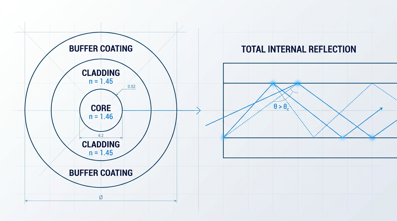
The mechanism that makes optical fibre work is elegantly simple. Light travelling through the glass core of a fibre is confined and guided along its length by a phenomenon called total internal reflection.
When a light ray travels from a medium with a higher refractive index into one with a lower refractive index — in fibre, from the core into the surrounding cladding — it bends away from the normal at the interface. As described by Snell's Law, there exists a specific angle of incidence, the critical angle, at which the refracted ray would run exactly along the boundary between the two media.
For any angle of incidence greater than the critical angle, no light escapes into the cladding at all — the entire ray is reflected back into the core with no loss of energy at the boundary. This is total internal reflection, and it is the operating principle of every optical fibre in service today.
The critical angle is determined by the ratio of the refractive indices of the two materials. In a typical silica fibre, the core has a refractive index of approximately 1.46 and the cladding approximately 1.45 — a difference of less than 1%, yet sufficient to confine light over thousands of kilometres.
The practical consequence is that light undergoes many thousands of reflections per metre as it propagates along the fibre, losing negligible energy at each reflection, and arrives at the far end with a signal integrity that electrical transmission over equivalent distances cannot approach.
Fibre structure: core, cladding, and buffer
An optical fibre has three concentric layers, each with a distinct function. The core is the central region of high-refractive-index glass through which light propagates. Surrounding it is the cladding, a layer of lower-refractive-index glass whose purpose is to create the refractive index differential that enables total internal reflection at the core-cladding boundary.
Encasing both is the buffer coating — a protective polymer layer that shields the glass from moisture, mechanical stress, and physical damage. The buffer plays no optical role; it is purely structural, preserving the integrity of the fibre during handling, installation, and long-term deployment.
Why light outperforms copper as a carrier
Optical fibres offer a combination of characteristics that copper conductors cannot replicate at high capacity and long distance: immunity to electromagnetic interference, very low signal attenuation, and the ability to carry enormous information bandwidths through a technique called wavelength-division multiplexing (WDM).
- EMI immunity: Light signals are unaffected by electromagnetic interference or crosstalk between adjacent cables, making fibre inherently more reliable in electrically noisy environments.
- Very low attenuation: Modern single-mode silica fibre achieves losses as low as approximately 0.2 dB/km at 1550 nm, enabling link spans of tens to hundreds of kilometres between amplifiers.
- Massive bandwidth via WDM: WDM allows dozens to hundreds of independent channels, each on a distinct wavelength, to travel simultaneously through a single fibre strand.
The 0.2 dB/km attenuation figure at 1550 nm is a reference anchor that recurs throughout this guide: it is the performance baseline against which fibre types, amplification strategies, and link budgets are all evaluated.
A brief history of the field
The story of optical telecommunications is, at its heart, a story about recognising that an apparent physical barrier was actually an engineering problem in disguise. By the mid-1960s, glass fibres were known to act as waveguides for light, but losses of around 1,000 dB/km made long-distance transmission seem physically hopeless.
In 1966, Charles Kao and George Hockham, working at Standard Telecommunication Laboratories in England, published a paper that reframed the problem entirely. They argued that the catastrophic losses observed in glass fibres were not a fundamental property of glass, but a consequence of impurities — and that sufficiently purified silica could achieve losses as low as 20 dB/km, making long-distance fibre transmission viable.
Kao and Hockham's 1966 paper showed that fibre's high losses were caused by impurities, not by fundamental physics — meaning the barrier to long-distance optical transmission was one of materials science, not of nature. Kao received the Nobel Prize in Physics in 2009 for this work.
The hypothesis was validated four years later. In 1970, Robert Maurer, Donald Keck, and Peter Schultz at Corning Glass Works fabricated a silica fibre with a loss of just 16 dB/km — below the 20 dB/km threshold Kao and Hockham had identified as the minimum for practical communications. By the end of the 1970s, loss had fallen further still, reaching approximately 0.2 dB/km at 1550 nm.
The next pivotal development came not in the fibre itself, but in how signals were sustained across long distances. In 1985, Robert Mears, then a graduate student at the University of Southampton's Optoelectronics Research Centre (ORC), demonstrated the first erbium-doped fibre amplifier (EDFA) — a device capable of amplifying optical signals directly, without converting them to electrical form.
The EDFA's significance was transformational: by keeping signals optical across intercontinental distances, it eliminated the need for electronic regeneration every few tens of kilometres and made it practical to amplify multiple wavelength channels simultaneously, opening the door to the high-capacity DWDM networks that carry global traffic today.
The transition from laboratory to global infrastructure was marked by the commissioning of TAT-8 in 1988 — the first transatlantic fibre-optic cable, connecting North America to Europe and demonstrating that fibre was ready to underpin the world's communications backbone.
The scale of modern optical infrastructure
The field Kao and Hockham seeded with a single paper now forms the physical substrate of the global internet. Submarine fibre-optic cables carry over 99% of all intercontinental data, with more than 1.5 million kilometres of submarine cable in service globally as of early 2026, spanning 694 active and planned cable systems.
With the definition, physics, and historical arc of optical telecommunications established, the natural next question is how a complete fibre optic link is actually assembled — which components convert, transmit, amplify, and receive the light signals that travel through it.
Core components of a fibre optic communication system
A fibre optic communication link is best understood as a chain of functional elements, each with a defined role in moving information from one point to another as light. The engineering elegance lies in how these elements — transmitter, fibre, amplifiers, receiver, and the passive interconnects that join them — are composed into a system whose reach and capacity far exceed anything achievable with electrical signalling alone.
Transmitters: converting electrical signals to light
The transmitter's function is to convert an electrical data stream into a modulated optical signal suitable for launch into the fibre. The dominant light sources in optical telecommunications are semiconductor laser diodes, which produce coherent output through stimulated emission in a forward-biased semiconductor junction; light-emitting diodes (LEDs) are used in lower-cost, lower-bandwidth applications but are largely confined to short-reach links where spectral purity is not critical.
Three laser types address the principal application classes. Distributed feedback (DFB) lasers incorporate a Bragg grating into the waveguide structure that forces single-longitudinal-mode operation, giving them the narrow linewidth required for long-haul dense WDM systems. Vertical-cavity surface-emitting lasers (VCSELs) use distributed Bragg reflector mirrors above and below a very short active cavity, lasing perpendicular to the substrate; their low threshold current and high modulation bandwidth make them the standard choice for short-reach multimode data centre links, typically at 850 nm. Fabry-Perot (FP) lasers, which emit across multiple longitudinal modes from a cavity formed between cleaved facets, are suited to short-reach links below roughly 40 km where chromatic dispersion is not a limiting factor.
Data is encoded onto the optical carrier by modulation — the process of varying a property of the light wave in proportion to the electrical data signal. In direct modulation, the laser drive current is varied directly to produce the optical bit stream; this is simple and cost-effective, but it introduces frequency chirp that interacts destructively with chromatic dispersion, limiting its use to lower bit rates and shorter spans.
At 25 Gbps and above, or over long-haul routes where chirp penalties accumulate, external modulation is preferred. Here the laser operates in continuous-wave mode and a separate electro-optic device — most commonly a Mach-Zehnder modulator (MZM) — imposes the data pattern onto the optical field, producing a chirp-reduced signal with higher extinction ratio and better tolerance to dispersion.
The fibre: guiding light over distance
Once launched from the transmitter, the optical signal propagates through the fibre, guided by total internal reflection at the core-cladding boundary — the physical mechanism established in the preceding section. The same medium serves links spanning a few metres in a data centre patch panel and transoceanic submarine cables running to thousands of kilometres; the fibre type, operating wavelength, and system design determine which regime applies.
The fibre itself is examined in detail in the next section. For the purposes of this component overview, the key point is that the fibre is the transmission channel: a passive optical waveguide whose loss and bandwidth characteristics set the fundamental constraints on every other element in the link.
Receivers: converting light back to electrical signals
At the far end of the link, the receiver's photodetector converts the incoming optical signal into a photocurrent, which the subsequent preamplifier and signal-conditioning electronics process to recover the transmitted bits. The two principal photodetector families in optical telecommunications are the p-i-n photodiode and the avalanche photodiode (APD).
A p-i-n device operates with an intrinsic layer between the p-type and n-type semiconductor regions, producing a photocurrent directly proportional to incident optical power with no internal gain; it is well suited to shorter links and applications with adequate received power. An APD applies a high reverse bias that triggers impact ionisation within the device, providing an internal multiplication factor typically between 10 and 100, improving sensitivity in low-light and long-haul scenarios at the cost of additional noise from the stochastic multiplication process.
Receiver sensitivity — defined as the minimum average optical power required at the detector to achieve a specified bit error rate (BER) — is the key figure of merit for any receiver design. It sets the hard floor on system reach: once the received power falls below this threshold, the link fails regardless of transmitter output, and the only remedies are amplification, lower-loss fibre, or a more sensitive detector.
Optical amplifiers: maintaining signal strength
Over long spans, fibre attenuation progressively reduces the signal power until it approaches the receiver sensitivity threshold. Erbium-doped fibre amplifiers (EDFAs) address this by amplifying the optical signal directly at the optical layer, without converting it back to electrical form — avoiding the cost and complexity of electronic regeneration at each intermediate point.
In practice, EDFAs are placed periodically along the route to compensate for accumulated fibre loss and keep the signal power within the operating range of the link. The detailed treatment of EDFA operation, gain characteristics, and placement strategy is covered in a later section; the point here is simply that the amplifier occupies a defined position in the system architecture between the transmitter and receiver.
Connectors and splices: joining the link
No practical link is a single unbroken strand of fibre. Cables are joined at intervals, terminated at equipment panels, and patched between systems using a combination of splices and connectors — passive interconnection elements that introduce discrete loss events at every junction.
Fusion splicing permanently joins two fibre ends by welding them together using an electric arc. It is the preferred method for outside plant and long-haul installations, yielding typical splice losses below 0.1 dB for singlemode fibre. Mechanical splicing holds fibre ends in alignment using a coupling device with index-matching gel, without heat; it is field-deployable where fusion equipment is unavailable, but carries somewhat higher typical loss, around 0.2 dB.
Connectors provide demountable connections at equipment interfaces and patch panels. The three types most commonly encountered in optical telecommunications are listed below, each associated with a characteristic deployment context.
- LC (Lucent Connector): Small-form-factor connector dominant in high-density data centre environments; average insertion loss around 0.2 dB for singlemode.
- SC (Subscriber Connector): Push-pull square-bodied connector widely used in telecom outside plant and access networks; average insertion loss around 0.2 dB.
- FC (Ferrule Connector): Threaded connector preferred for test equipment and precision singlemode applications where vibration resistance and repeatability are required.
The insertion loss of each connector or splice — the optical power lost at that junction — accumulates across the full link. Typical factory-polished singlemode connectors produce losses below 0.3 dB per mated pair; the FOA loss estimation guide recommends budgeting approximately 0.3 dB per connector for adhesive/polish types. These discrete losses, alongside fibre attenuation, form the basis of the link loss budget examined in detail later in this guide.
Before EDFAs, every long-haul span required electronic regenerators that decoded the optical signal to electrical, re-amplified it, and retransmitted it — a process that was both costly and inherently bit-rate-specific. All-optical amplification removed that constraint, allowing a single installed fibre plant to carry increasing capacity as modulation formats and line rates evolved, without replacing the amplification infrastructure.
With the component model in place — transmitter generating and modulating the signal, fibre guiding it over distance, amplifiers maintaining power along the route, receiver recovering the electrical data, and connectors and splices joining every segment — the system can be understood as a coherent end-to-end architecture rather than a collection of parts.
The medium through which the signal travels determines much of what is possible: its modal behaviour, attenuation profile, and bandwidth capacity shape every other design decision. The next section examines the optical fibre itself in detail — covering the distinction between single-mode and multimode fibre and the characteristics that govern each type's role in optical telecommunications.
Types of optical fibre: single-mode vs multimode
Of all the decisions made when designing an optical telecommunications link, the choice of fibre type has some of the most far-reaching consequences — determining the maximum reach, the achievable data rate, the transceiver technology, and ultimately the cost structure of the entire system.
All telecommunications-grade silica fibre shares the same 125 µm cladding diameter, but it is the core that defines the category — specifically, how large the core is and what refractive index profile it carries.
Single-mode fibre (SMF)
Single-mode fibre has a core diameter of approximately 8–10 µm — narrow enough that only the fundamental propagation mode can exist within it.
The physical consequence of supporting a single mode is the elimination of intermodal dispersion: because there is only one propagation path, all optical energy arrives at the receiver at the same time, with no pulse broadening from differential mode delay.
This makes SMF the natural choice for any application where reach or data rate is the binding constraint — long-haul terrestrial routes, submarine systems, metropolitan rings, and high-capacity access backhaul all rely on SMF as their default medium.
Standard SMF achieves typical attenuation of around 0.20 dB/km at 1550 nm, while ultra-low-loss variants reach below 0.15 dB/km at that wavelength, enabling unamplified spans of tens of kilometres and amplified links extending hundreds of kilometres.
Multimode fibre (MMF)
Multimode fibre has a much larger core: 50 µm for modern laser-optimised designs, and 62.5 µm for legacy OM1 fibre.
The larger core admits many simultaneous propagation modes, each travelling a slightly different path and therefore arriving at the receiver at slightly different times — a phenomenon known as intermodal dispersion (or modal dispersion), which broadens transmitted pulses and limits the bandwidth-distance product.
MMF also exhibits higher attenuation than SMF: at 850 nm, the primary operating wavelength for short-reach MMF transceivers, maximum attenuation is specified at 3.0–3.4 dB/km depending on fibre grade, compared to SMF's 0.35 dB/km at 1310 nm.
Despite these limitations, MMF remains the dominant medium for data centre and enterprise campus deployments at distances below 550 m, because the 850 nm VCSELs used with MMF are significantly cheaper to manufacture than the DFB lasers required for SMF — a cost advantage that outweighs the fibre's distance ceiling in most intra-building scenarios.
The OM grading system classifies multimode fibres by their bandwidth-distance capability, providing a practical shorthand that procurement and standards documents use consistently.
| Fibre Type | Core Diameter | Typical Attenuation | Typical Reach at 10 Gbps | Primary Use Case |
|---|---|---|---|---|
| SMF (G.652) | 8.2 µm | ~0.20 dB/km @ 1550 nm | >40 km (amplified: hundreds of km) | Long-haul, metro, access backhaul |
| OM1 (62.5 µm MMF) | 62.5 µm | 3.4 dB/km @ 850 nm | 33 m @ 850 nm | Legacy enterprise; largely superseded |
| OM2 (50 µm MMF) | 50 µm | 3.0 dB/km @ 850 nm | 150 m @ 850 nm | Enterprise LAN; short backbone runs |
| OM3 (50 µm, laser-opt.) | 50 µm | 2.8 dB/km @ 850 nm | 300 m @ 850 nm (10GBASE-SR) | Data centre, enterprise backbone |
| OM4 (50 µm, laser-opt.) | 50 µm | 2.8 dB/km @ 850 nm | 550 m @ 850 nm (10GBASE-SR) | Data centre, high-density backbone |
| OM5 (50 µm, wideband) | 50 µm | 2.2 dB/km @ 850 nm | 400 m @ 850 nm (IEEE 802.3ae) | Data centre SWDM, 40/100G+ applications |
Comparison of SMF and key MMF grades on core diameter, attenuation, typical reach at 10 Gbps, and primary use case — sourced from Corning, OFS, and ITU-T specifications.
The table makes the trade-off explicit: SMF's reach advantage is orders of magnitude greater than any MMF grade, but OM3 and OM4 cover the vast majority of real data centre link lengths — Corning's deployment data shows that 90–95% of installed OM3/OM4 links operate within 100 m, well inside the capability of either grade at 40G or 100G.
OM5, the newest grade, extends the wideband specification to cover the 850–953 nm range for short-wavelength division multiplexing (SWDM) applications, enabling 100G duplex transmission over two fibres to 150 m — a meaningful reach extension over OM4 for the SWDM transceiver ecosystem.
Graded-index multimode fibre
Early multimode fibre used a step-index design: an abrupt refractive index boundary at the core-cladding interface, with a uniform index throughout the core.
In a step-index core, higher-order modes travel longer zig-zag paths and arrive later than lower-order modes, producing severe pulse broadening that limits usable bandwidth to a fraction of what the fibre's raw bandwidth might suggest.
Modern MMF uses a graded-index design instead: the refractive index decreases parabolically from the centre of the core outward toward the cladding boundary, rather than dropping sharply at the interface.
This parabolic profile causes higher-order modes, which travel longer paths near the periphery, to propagate faster in the lower-index outer region — partially compensating for the additional path length and substantially equalising the group velocities of all modes.
The ITU-T Optical Fibre Handbook notes that graded-index design can reduce pulse spreading by a factor of 100 or more compared to step-index, which is what makes the bandwidth-distance products of OM3 and OM4 achievable in practice.
OM3 and OM4 fibres achieve their 2,000 and 4,700 MHz·km effective modal bandwidth specifications not through larger cores or better glass purity, but through precise control of the parabolic refractive index profile — a manufacturing challenge that defines the quality difference between fibre grades.
All current laser-optimised 50 µm MMF — OM2 through OM5 — uses graded-index construction; step-index multimode is largely confined to legacy installations and specialist applications outside telecommunications infrastructure.
ITU-T single-mode fibre standards
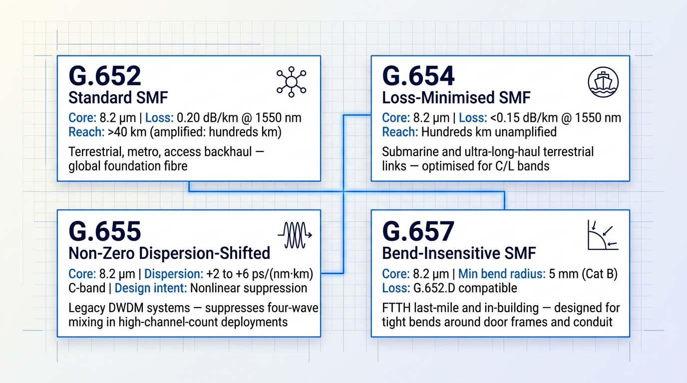
For single-mode fibre, the ITU-T G-series recommendations define the parameters that govern procurement, interoperability, and system design across the industry — four of which the practising engineer will encounter repeatedly.
- G.652: Standard SMF with zero-dispersion wavelength around 1310 nm; the most widely deployed fibre globally, used in terrestrial, metro, and access networks.
- G.654: Cut-off-shifted, loss-minimised SMF optimised for the 1530–1625 nm window; used where ultra-low attenuation is paramount, such as long submarine links.
- G.655: Non-zero dispersion-shifted SMF engineered to maintain a small but non-zero chromatic dispersion in the C-band, suppressing nonlinear effects in dense multi-channel systems.
- G.657: Bend-insensitive SMF for access networks and in-building installations; the standard choice for FTTH drop cables where tight bends are unavoidable.
G.652 is the foundation of the global fibre plant — first standardised in 1984 and continuously revised, with subcategories A through D accommodating evolving PMD and water-peak attenuation requirements while remaining backward-compatible with legacy G.652 cables.
G.654 sacrifices the dispersion-optimised 1310 nm window in favour of an exceptionally low loss floor in the C and L bands, making it the preferred choice for repeatered submarine systems and long terrestrial amplified links where every fraction of a dB/km matters.
G.655 addresses a specific failure mode of early DWDM deployments: when many optical channels co-propagate at near-zero dispersion, four-wave mixing and other nonlinear effects grow rapidly and corrupt the signal.
By engineering a small but non-zero dispersion coefficient across the C-band (1530–1565 nm), G.655 fibre suppresses those nonlinear interactions without abandoning the low-attenuation window — a deliberate design compromise that enabled the first generation of high-channel-count DWDM systems.
G.657 was introduced specifically to address the mechanical realities of FTTH last-mile deployment, where cables must navigate tight bends around door frames, through conduit bends, and across building risers.
Category A fibres (G.657.A1, G.657.A2) are fully compliant with G.652.D and can be used throughout the network; Category B fibres (G.657.B2, G.657.B3) tolerate minimum bend radii as low as 5 mm and are optimised for the most demanding in-building routes, though with slightly different splicing characteristics.
Choosing between SMF and MMF
The selection framework is straightforward in principle: distance and environment are the primary axes, with transceiver economics as the decisive factor at shorter reaches.
For any link beyond approximately 550 m at 10 Gbps — or beyond 1 km at 1 Gbps — SMF is the only viable option; multimode fibre simply cannot support the required bandwidth-distance product regardless of grade.
Below that threshold, the decision becomes economic rather than technical: OM3 or OM4 fibre with 850 nm VCSEL transceivers is materially cheaper per port than SMF with DFB laser transceivers, and the fibre itself is easier to terminate and connect in the field.
For metro and long-haul links, the choice within SMF depends on the application: G.652 for the overwhelming majority of terrestrial deployments, G.654 where submarine or ultra-long-haul loss budgets are the binding constraint, G.655 in legacy DWDM systems where nonlinear suppression was engineered into the fibre, and G.657 wherever the physical installation environment imposes tight bends.
Neither fibre type is universally superior — the right choice is always context-dependent, and experienced network designers treat fibre selection as a system-level decision that accounts for reach, data rate, transceiver cost, and the physical environment in equal measure.
Understanding which fibre is in use also determines which signal degradation mechanisms dominate: SMF eliminates intermodal dispersion entirely but remains subject to chromatic dispersion and attenuation, while MMF contends with all three — and the way those mechanisms interact with data rate and reach is the subject of the next section.
Signal degradation: attenuation, dispersion, and nonlinear effects
Optical system design is a serious engineering discipline precisely because light, for all its speed and bandwidth, degrades as it travels through glass. Three categories of impairment govern this degradation: attenuation, which steadily drains optical power from the signal; dispersion, which smears pulses in time until adjacent bits become indistinguishable; and nonlinear effects, which corrupt the signal's phase and spectrum when optical intensity is high. Understanding each — its physical origin, its scaling behaviour, and its system-level consequence — is the prerequisite for understanding every architectural and engineering choice that follows.
Attenuation
Attenuation is the exponential decay of optical power with propagation distance, expressed in dB/km. Two intrinsic mechanisms define the loss spectrum of silica fibre: Rayleigh scattering, which arises from sub-wavelength density fluctuations frozen into the glass during manufacture and scales with the inverse fourth power of wavelength (1/λ⁴), making it the dominant loss mechanism at shorter wavelengths; and infrared absorption, which arises from molecular vibration in the silica lattice and dominates at longer wavelengths.
The interplay of these two mechanisms produces a loss minimum in the region around 1550 nm — the point where Rayleigh scattering has fallen sufficiently and infrared absorption has not yet risen to dominate. This is not an incidental feature: the entire DWDM and EDFA ecosystem is engineered around this window precisely because it is where silica fibre is most transparent.
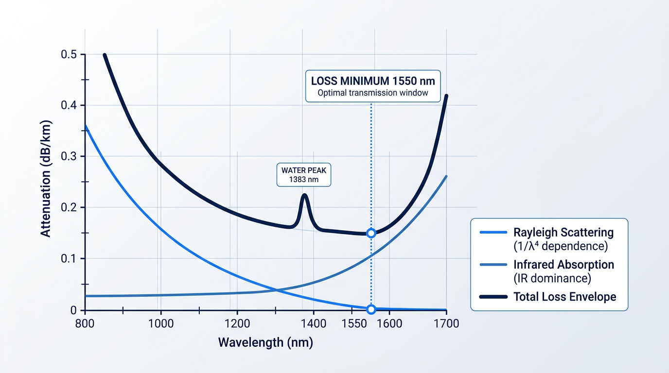
Extrinsic attenuation contributors add to this intrinsic baseline. OH⁻ ion absorption — the so-called water peak — creates a pronounced loss spike near 1383 nm, caused by hydroxyl ions incorporated during fibre manufacture; low-water-peak variants of G.652 fibre are engineered specifically to suppress this peak and open the E-band for transmission. Transition-metal impurities from the manufacturing process also absorb at specific wavelengths, though modern fabrication techniques have reduced these to near-negligible levels.
Bending losses remain the most practically significant extrinsic contributors in deployed systems. Macrobending occurs when a fibre is routed around a bend tighter than its critical radius, causing guided modes to radiate energy into the cladding. Microbending arises from microscopic deformations along the fibre axis — typically from mechanical stress, poor cabling, or inadequate buffer protection — and produces distributed, often difficult-to-localise loss.
The practical engineering consequence is direct: attenuation sets the maximum unrepeatered span length in any long-haul system. Without amplification, signal power decays exponentially until it falls below the receiver's sensitivity threshold, and that distance is determined by the fibre's loss coefficient and the available power margin at launch. This is the physical reason why optical amplifiers must be placed periodically along a long-haul link.
Chromatic Dispersion
Chromatic dispersion arises because the group velocity of light in a single-mode fibre is wavelength-dependent: different spectral components of a modulated pulse travel at slightly different speeds, causing the pulse to broaden in time as it propagates. At the receiver, this temporal broadening reduces the eye opening and ultimately makes adjacent bits indistinguishable — a fundamental limit on the achievable bit rate over a given distance.
Chromatic dispersion has two physical components. Material dispersion arises from the intrinsic wavelength-dependence of the silica refractive index. Waveguide dispersion arises from the geometry of the core-cladding structure, which guides different wavelengths with different effective indices. In standard G.652 single-mode fibre, these two components partially cancel near 1310 nm — the zero-dispersion wavelength — but at 1550 nm, where loss is minimised, the residual dispersion is approximately 17 ps/nm·km.
Dispersion accumulates linearly with distance and its impact scales with both the dispersion coefficient and the signal's spectral bandwidth, which in turn scales with bit rate. This relationship is captured by the concept of the bit-rate-distance product: doubling the bit rate halves the tolerable span length for a given dispersion coefficient, making dispersion management progressively more demanding as system capacity increases.
The engineering responses to this 1550 nm dispersion penalty shaped fibre standards for decades. Dispersion-shifted fibre (G.653) was developed to move the zero-dispersion point to 1550 nm, eliminating the penalty at the low-loss window. However, as discussed in the next subsection, near-zero dispersion at 1550 nm proved catastrophic for multi-channel systems because it enabled efficient four-wave mixing. Non-zero dispersion-shifted fibre (G.655) was the practical resolution: it retains a small but non-zero dispersion at 1550 nm — sufficient to suppress four-wave mixing while remaining manageable through dispersion compensation.
Polarisation Mode Dispersion
Polarisation mode dispersion (PMD) is a distinct impairment mechanism arising from the fact that real single-mode fibres are not geometrically perfect. Core ellipticity, internal stress from manufacturing, and external mechanical forces all introduce slight birefringence — meaning the two orthogonal polarisation states of the fundamental mode propagate at marginally different group velocities. The resulting differential group delay (DGD) between these polarisation components broadens the received pulse in a manner analogous to chromatic dispersion, but with a fundamentally different character.
PMD is stochastic in nature: the birefringence axes and their magnitudes vary randomly along the fibre length and fluctuate with temperature, vibration, and mechanical perturbation. This statistical behaviour makes PMD significantly harder to compensate than chromatic dispersion, which is deterministic and stable. For long fibres with random birefringence coupling, the mean DGD grows with the square root of distance — a slower scaling than chromatic dispersion, but one that becomes serious at high bit rates over transoceanic or continental spans.
PMD is largely inconsequential at bit rates below 2.5 Gbps over typical terrestrial distances, but at 10 Gbps and above it becomes a design-limiting impairment. Modern coherent receivers equipped with digital signal processing (DSP) can track and compensate PMD electronically in real time, which is one of the principal engineering advantages of coherent transmission — a technology addressed in the next section.
Nonlinear Effects
In ordinary bulk glass, the refractive index is effectively independent of optical intensity. Inside a single-mode fibre core, however, the combination of high optical power density and propagation distances measured in hundreds or thousands of kilometres allows nonlinear effects to accumulate to engineering significance. These effects fall into two categories: those arising from the Kerr effect — the intensity-dependence of the refractive index — and those arising from inelastic scattering processes involving the glass medium itself.
In multi-channel systems, where many wavelengths co-propagate at high combined power, the nonlinear interactions between channels compound rapidly with channel count, making nonlinearity a defining constraint on system capacity.
- Self-phase modulation (SPM): A channel's own intensity modulates the refractive index it experiences, inducing a phase shift that broadens the signal spectrum and interacts with chromatic dispersion to compress or broaden pulses.
- Cross-phase modulation (XPM): Intensity fluctuations in one channel modulate the phase of co-propagating channels via the Kerr effect, producing inter-channel crosstalk that worsens as channel count and launch power increase.
- Four-wave mixing (FWM): Three co-propagating waves generate new spectral components at combinations of their frequencies. FWM is most efficient when channels are closely spaced and chromatic dispersion is near zero — the core reason G.653 fibre proved unsuitable for DWDM.
- Stimulated Raman scattering (SRS): An inelastic process in which photons from shorter-wavelength channels transfer energy to longer-wavelength channels, downshifted by approximately 13 THz in silica, producing a systematic power tilt across the channel spectrum.
- Stimulated Brillouin scattering (SBS): A narrowband inelastic interaction with acoustic phonons that generates a backward-propagating Stokes wave, imposing a relatively low threshold on the maximum launch power of narrow-linewidth continuous-wave signals.
These effects collectively impose a ceiling on the launch power that can be used in a long-haul system. The tension is fundamental: attenuation favours high launch power, because a stronger signal maintains margin above the receiver noise floor for a longer distance before amplification is needed. Nonlinear effects favour low launch power, because the magnitude of Kerr-based and scattering-based impairments grows with intensity. The optimal launch power — the point that maximises reach while keeping nonlinear penalties within tolerance — is therefore not a fixed specification but a system-level design parameter that must be determined for each span configuration.
Every long-haul optical system operates within a power corridor bounded below by attenuation (too little power and the signal drowns in noise) and above by nonlinearity (too much power and the signal corrupts itself and its neighbours). Finding the optimal launch power within that corridor is one of the defining engineering tasks in DWDM system design.
None of these impairments operates in isolation: the interaction between chromatic dispersion and SPM or XPM is itself a coupled phenomenon, where the dispersion sign and magnitude determine whether nonlinear phase shifts compress or broaden pulses. Managing one impairment category without accounting for the others is a reliable path to suboptimal system performance.
These three impairment categories — attenuation, dispersion, and nonlinear effects — are the physical constraints that have driven every major advance in optical telecommunications engineering, from periodic amplification to dispersion-compensating fibre to coherent detection with DSP. The engineering responses to each are the subject of the next section.
Optical amplification, multiplexing, and coherent transmission
Before all-optical amplification existed, every long-haul optical link depended on electronic regenerators spaced every few tens of kilometres: the optical signal was converted to electrical, cleaned up, and re-converted back to light — a process known as OEO conversion.
Each regenerator was wavelength-specific and bit-rate-specific, making multi-wavelength systems prohibitively expensive and architecturally rigid; scaling capacity meant deploying more regenerators, not simply adding channels to the same fibre.
That bottleneck was broken by the erbium-doped fibre amplifier, a device that amplifies optical signals directly in the optical domain — no conversion, no wavelength specificity, and gain spanning tens of nanometres simultaneously.
Erbium-doped fibre amplifiers
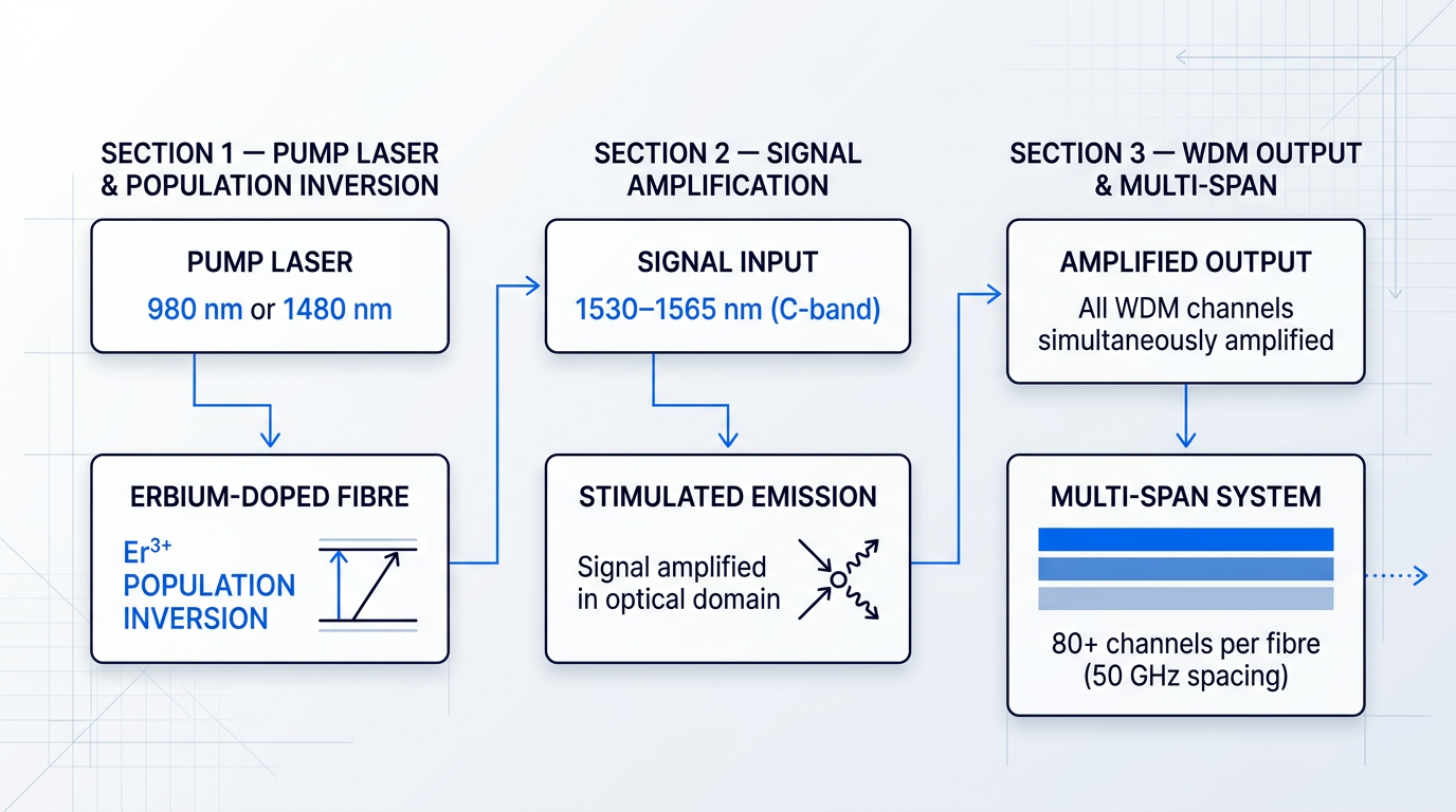
An EDFA works by splicing a length of silica fibre doped with trivalent erbium ions (Er³⁺) into the signal path, then injecting pump light from a laser diode operating at either 980 nm or 1480 nm.
At 980 nm, pump photons excite erbium ions from the ground state to a short-lived higher energy level, from which they rapidly relax into the metastable ⁴I₁₃/₂ state — creating population inversion; at 1480 nm, the pump drives transitions directly into the upper manifold of that same gain level, trading the cleaner inversion of 980 nm pumping for higher efficiency in high-power configurations.
When a signal photon in the 1530–1565 nm window passes through the doped fibre, it triggers stimulated emission from the inverted erbium ions, producing an identical photon and amplifying the signal without any OEO conversion.
The EDFA was first demonstrated by Robert Mears and colleagues at the University of Southampton's Optoelectronics Research Centre (ORC) in 1985, with the achievement reported in Electronics Letters and the invention filed in UK Patent Applications 8520300/8520301 — a development widely regarded as one of the most significant in the history of modern telecommunications.
The Er³⁺ gain spectrum in silica glass spans the C-band (1530–1565 nm), which aligns precisely with the loss minimum of silica fibre near 1550 nm established in earlier sections of this guide — a coincidence of physics that made the EDFA exceptionally well-suited to long-haul transmission.
Extending pump power and adjusting erbium inversion levels opens the L-band (1565–1625 nm), pushing the amplification window out to 1625 nm and approximately doubling the available spectral real estate when C and L bands are operated together.
The choice of operating band is a fundamental system design decision — not a configuration detail — because it determines channel count, reach, amplifier architecture, and the long-term upgrade path of the entire network; C+L band deployment is a strategic capacity lever in modern DWDM infrastructure, not merely an incremental option.
Four engineering parameters govern EDFA performance in practice, and understanding them is essential to designing a multi-span system that meets its optical signal-to-noise ratio (OSNR) budget.
- Gain: Typically 20–40+ dB per stage; gain exceeding 30 dB is achievable with a few milliwatts of pump power in well-designed erbium fibre.
- Noise figure: Practical EDFAs achieve 4–6 dB noise figure; 980 nm pumping yields lower noise than 1480 nm, making it preferred for pre-amplifier stages.
- Amplified spontaneous emission (ASE): The principal noise mechanism: spontaneously emitted photons are amplified alongside the signal, accumulating across a multi-span chain and degrading OSNR.
- Gain-flattening filters: Optical filters inserted after the active fibre to equalise gain across the amplification band, ensuring all WDM channels receive uniform amplification.
- Booster amplifier: Placed immediately after the transmitter to raise launch power into the first fibre span; optimised for high output power.
- In-line amplifier: Positioned at repeater sites along the route, typically every 60–100 km on terrestrial links, to compensate for span loss without OEO conversion.
- Pre-amplifier: Placed immediately before the receiver to boost a weak incoming signal; optimised for low noise figure rather than output power.
In a long chain of in-line amplifiers, ASE accumulates with each stage, progressively degrading OSNR; the governing design metric for any multi-span system is therefore the end-of-line OSNR margin, which must remain above the receiver's threshold across the full channel plan and over the system's design lifetime.
Wavelength-division multiplexing: CWDM and DWDM
Wavelength-division multiplexing (WDM) transmits multiple optical channels simultaneously on a single fibre, each at a distinct wavelength (or colour), combined at the transmit end by a multiplexer and separated at the receive end by a demultiplexer.
CWDM (coarse WDM), standardised in ITU-T G.694.2, uses 20 nm channel spacing across a wavelength range from 1271 nm to 1611 nm, supporting up to 18 channels; its wide spacing tolerates uncooled lasers and lower-cost passive components, making it well-suited to cost-sensitive metro and access applications.
DWDM (dense WDM), standardised in ITU-T G.694.1, uses a frequency grid anchored to 193.1 THz with channel spacings from 12.5 GHz to 100 GHz; at 50 GHz spacing, a C-band system can carry 80 or more channels on a single fibre, and the 50 GHz and 100 GHz spacings have been the most widely deployed in long-haul networks.
The reason EDFAs made DWDM economically viable is direct: a single EDFA simultaneously amplifies every WDM channel within its gain window, eliminating the per-wavelength, per-bit-rate regenerators that would otherwise be required at every repeater site.
A single EDFA amplifies all DWDM channels within its gain window simultaneously — this is the physical fact that made multi-terabit long-haul networking economically and technically viable, replacing hundreds of wavelength-specific regenerators with a single all-optical stage.
Combining C-band and L-band amplification approximately doubles the number of available DWDM channels per fibre, and this C+L band strategy — governed by the same ITU-T G.694.1 frequency grid — is the primary spectral capacity lever available to operators before moving to more radical architectural changes such as additional fibre pairs or space-division multiplexing.
Coherent transmission and modulation formats
Early optical systems used on-off keying (OOK) — encoding a binary one by turning the light on and a zero by turning it off — which exploits only the amplitude of the optical carrier and yields just one bit per symbol.
Coherent detection changes the fundamental encoding strategy by exploiting the amplitude, phase, and polarisation of the optical carrier together, multiplying the information carried per symbol by the number of distinguishable states in each dimension.
The modulation format hierarchy reflects this: DP-QPSK (dual-polarisation quadrature phase shift keying) encodes four bits per symbol across two polarisations and became the workhorse of 100G long-haul systems; 16QAM encodes 16 constellation points for 200G and 400G applications; and 64QAM pushes spectral efficiency further for higher-capacity shorter-reach links where the OSNR budget is more generous.
Coherent receivers paired with high-speed digital signal processing (DSP) can compensate for chromatic dispersion and polarisation mode dispersion entirely in the electrical domain — removing the need for physical dispersion-compensating fibre in many deployments and simplifying system architecture considerably.
The commercial capacity trajectory of coherent transmission is one of the most sustained engineering progressions in telecommunications: Nortel announced the first commercial coherent 40G system in March 2008, and by late 2009 the first live 100G coherent network was operating on Verizon's Paris–Frankfurt route; 400G is now widely deployed across carrier networks globally; 800G entered commercial shipment and deployment from 2020 onwards, with over 100,000 800G coherent modems shipped by late 2023; and 1.6 Tbps single-carrier solutions have been announced for near-term availability.
This is an ongoing trajectory, not a completed story — vendor roadmaps and field trials continue to push single-wavelength capacity and reach simultaneously, with each generation of DSP unlocking modulation formats that would have been computationally impractical in the previous one.
As coherent DWDM approaches the Shannon capacity limit of conventional single-mode fibre, the next frontier is space-division multiplexing (SDM): multi-core fibre (MCF) and few-mode fibre (FMF) multiply per-cable capacity by exploiting independent spatial paths within a single physical cable rather than squeezing more bits into each existing channel — a topic covered fully in the future trends section of this guide.
Beyond telecommunications, the EDFA platform underpins a growing range of demanding applications where the amplifier must be engineered around the specific use case rather than selected from a fixed catalogue: high-power LiDAR, free-space optical communications (FSOC), distributed acoustic sensing, and directed-energy research all place requirements on operating band, output power, pulse regime, and integration envelope that a standard telecom-grade amplifier is not designed to meet.
For these applications, Woodrow Scientific Limited's Custom EDFA represents the engineering approach of building the amplifier around the application rather than adapting the application to the amplifier: designed, built, qualified, and supported entirely in-house in Southampton — where the EDFA was invented — on patented technology, with engineering heritage rooted directly in the ORC.
The platform is configurable across C-band, L-band, or dual C+L from a single unit through a single cable, with output power, pulse regime (CW, short-pulse, or custom), cooling (air or water), form factor, and control firmware all specified per project; WSL pushes pulse energies above 10 mJ, peak powers above 100 kW, and average powers above 100 W — at the leading commercially-available levels for erbium fibre — and the complete platform carries CE and UKCA certification, operates at the eye-safer 1550 nm wavelength with reduced-hazard-zone builds available, and is backed by direct engineering support throughout integration.
This distinction between an in-house manufacturer and a reseller or importer matters practically: only a company that designs and builds its own amplifiers can deeply support integration, modify the design for a new requirement, or accelerate spares and fixes when a programme demands it.
With amplification, multiplexing, and coherent modulation now established as the core enabling technologies, the following section examines how these capabilities are assembled into deployable network architectures — from passive optical networks serving the access layer to the OTN transport frameworks that carry traffic across continents.
Optical network architectures: PON, AON, and OTN
Every component and phenomenon covered so far — the lasers, the fibres, the amplifiers, the multiplexed wavelengths — exists in service of a larger purpose: building networks that move information between real places at real scale. The physics becomes engineering, and the engineering assembles into recognisable architecture families, each suited to a different layer of the network hierarchy and a different set of deployment constraints.
Passive optical networks (PON)
A passive optical network uses a point-to-multipoint topology in which a single fibre from the central office fans out to multiple customer premises via an unpowered optical splitter in the distribution network. The three functional elements are: the Optical Line Terminal (OLT) at the central office, which aggregates traffic and manages the downstream and upstream transmission; the Optical Network Units (ONUs) or Optical Network Terminals (ONTs) at customer premises, which terminate the optical signal; and the passive optical splitter between them, which requires no power supply, no active management, and no environmental enclosure.
The defining characteristic of PON is that there are no active electronics between the OLT and the ONU — the distribution network is entirely passive, which substantially reduces outside plant complexity and maintenance obligations compared with architectures that place powered equipment in the field.
PON technology has evolved through successive ITU-T G-series standards, each raising capacity while preserving the same passive distribution infrastructure. The five principal generations with commercial deployments are listed below.
- GPON (ITU-T G.984): 2.488 Gbps downstream, 1.244 Gbps upstream. The most widely deployed PON generation; supports Ethernet, ATM, and TDM traffic.
- XG-PON (ITU-T G.987): 10 Gbps downstream, 2.5 Gbps upstream. Designed as an asymmetric upgrade path for GPON operators.
- XGS-PON (ITU-T G.9807): 10 Gbps symmetric downstream and upstream. Addresses the upstream bottleneck of XG-PON.
- NG-PON2 (ITU-T G.989): 40 Gbps aggregate using TWDM — up to four 10 Gbps wavelength channels. Coexistent with GPON and XG-PON on the same ODN.
- 50G-PON (ITU-T G.9804): Current leading-edge standard; achieves 50 Gbps per wavelength over 20 km or 40 km using advanced DSP and FEC.
Typical split ratios range from 1:32 to 1:128, and the standard physical reach from OLT to ONU is 20 km, with logical reach extendable to 60 km via reach extenders in some standards.
The inherent trade-off in PON is that the splitter divides both downstream optical power and upstream capacity among all connected ONUs — bandwidth is shared across the split ratio, not dedicated to individual users.
Active optical networks (AON)
An active optical network takes the contrasting approach: each customer has a dedicated fibre run, with active Ethernet switches placed in the distribution network between the central office and the customer premises. Those switches — powered, managed, and housed in environmental enclosures — are the defining element that distinguishes AON from PON.
Because each customer's fibre is dedicated end-to-end, AON delivers guaranteed bandwidth per subscriber with no sharing; a user's link capacity is not affected by the traffic patterns of neighbours on the same distribution segment.
The cost implication is significant: the active field switches require power supply infrastructure, weatherproof enclosures, and ongoing maintenance, raising both CAPEX and OPEX relative to PON's passive plant. In return, the Ethernet switching layer integrates naturally with enterprise and carrier Ethernet service models, making it straightforward to deliver differentiated service tiers on a per-customer basis.
PON vs AON: key trade-offs
Neither architecture is universally superior. The practical choice between PON and AON turns on deployment context: the density of the subscriber base, the mix of service tiers required, the cost of powering field equipment, and the operator's preference for outside plant simplicity versus per-customer service flexibility.
| Trade-off axis | PON | AON |
|---|---|---|
| Topology | Point-to-multipoint; single OLT port serves multiple ONUs via passive splitter | Point-to-point; dedicated fibre from central office (or active switch) to each customer |
| Bandwidth model | Shared across the split ratio (e.g. 1:32 to 1:128); upstream uses TDMA scheduling | Dedicated per customer; full link capacity available to each subscriber independently |
| Outside plant | Passive splitters — no field power, no active management, no environmental housing required | Active Ethernet switches in the field — require power supply, enclosures, and maintenance |
| Operational complexity | Simple once installed; no powered field equipment to manage or replace | Higher OPEX; field switches need power, software management, and periodic maintenance |
| Service flexibility | Shared medium constrains per-customer differentiation at the physical layer | Dedicated fibre per customer enables straightforward differentiated service tiers |
| Scalability | Single OLT port serves many users via splitting; fibre count from CO is low | One port and one fibre per customer; port count and fibre count scale linearly with subscribers |
Direct comparison of PON and AON across the five principal deployment trade-off axes to assist network planners in assessing which architecture suits a given context.
For high-density residential deployments where outside plant simplicity and low maintenance cost are priorities, PON's passive distribution network is typically the more economical choice. Where the subscriber base demands guaranteed bandwidth, granular service differentiation, or integration with existing enterprise Ethernet infrastructure, AON's dedicated-fibre model justifies its higher operational overhead.
Optical transport networks (OTN)
Optical Transport Network (OTN), defined by ITU-T G.709, is a standardised digital wrapper framework for transporting client signals — including Ethernet and SDH — transparently over optical infrastructure. Where PON and AON are access-layer architectures connecting end users to the network edge, OTN operates in the metro and long-haul transport domains, carrying aggregated traffic between nodes across cities and continents.
OTN defines a four-layer hierarchy, each adding overhead and capability as the client signal is wrapped for transport.
- OPU (Optical channel Payload Unit): Carries the client payload. The client signal is mapped into the OPU, which forms the innermost layer of the OTN wrapper.
- ODU (Optical channel Data Unit): Wraps the OPU and adds overhead for tandem connection monitoring (TCM) and fault management across network segments.
- OTU (Optical channel Transport Unit): Wraps the ODU and adds forward error correction (FEC) and frame synchronisation for physical-layer transport.
- OCh (Optical channel): The individual wavelength on the DWDM fibre that carries the OTU signal end-to-end between nodes.
The capabilities OTN adds over legacy SONET/SDH are substantial. The ITU-T G.709 Reed-Solomon FEC provides approximately 6.2 dB of coding gain in signal-to-noise ratio — compared with 4 dB for SDH in-band FEC — enabling longer spans or higher-order modulation at equivalent error rates. G.709 also defines six levels of tandem connection monitoring (TCM), allowing operators to isolate and attribute faults to specific network segments without disrupting end-to-end service. Client signals are carried bit-transparently: the original signal is encapsulated without modification and recovered intact at the far end.
OTN's role in the overall network stack is to provide the management and operations layer that sits on top of the DWDM optical layer covered in the previous section, giving operators the visibility, fault isolation, and performance monitoring needed to run large-scale transport networks carrying coherent high-capacity signals.
Reconfigurable Optical Add-Drop Multiplexers (ROADMs) are the switching nodes that give modern DWDM transport networks their flexibility. A ROADM can add, drop, or pass through individual wavelengths in a DWDM system without converting signals to electrical form, and can be reconfigured remotely — redirecting wavelengths across the network without dispatching field technicians. This capability enables mesh network topologies in which wavelengths are routed dynamically, and it is the physical-layer foundation on which software-defined optical networking is built.
PON and AON solve the access problem — connecting end users to the network edge. OTN and DWDM solve the transport problem — moving aggregated traffic between nodes at scale. Choosing the right architecture requires first identifying which layer of the network hierarchy you are designing for; the two families are complementary, not competing.
Taken together, these architecture families occupy distinct but complementary layers: PON and AON form the access layer, connecting residential and enterprise users to the network edge; OTN and DWDM form the metro and long-haul transport layer, aggregating and carrying that traffic across the wider network. With this layered model in place, the next step is to see how these architectures appear in practice — and why different deployment contexts consistently favour different members of the family.
Industry applications of optical telecommunications
Every technical concept covered in this guide — the 0.2 dB/km loss minimum at 1550 nm, EDFA gain, DWDM channel grids, PON splitter ratios, Rayleigh backscatter — exists because real infrastructure demands it. From the repeater housings resting on the ocean floor to the fibre strand embedded in a railway embankment, optical telecommunications is not an abstraction. It is the physical substrate of the modern world.
Telecommunications backbone and long-haul networks
The foundational application of optical fibre — and the one that drove the development of every technology this guide has covered — is the terrestrial long-haul backbone: the fibre routes connecting cities, regions, and national networks.
DWDM over single-mode fibre is the enabling combination, packing dozens to hundreds of independent wavelength channels onto a single fibre pair and delivering aggregate capacities in the terabit-per-second range across multi-thousand-kilometre routes.
What makes these distances viable is the EDFA. As established in the amplification section, EDFAs amplify all DWDM channels simultaneously in the optical domain, eliminating the need for electronic regeneration at every span and allowing signals to traverse thousands of kilometres with only periodic amplification.
ROADM-based mesh architectures, as covered in the network architecture section, give operators the flexibility to add, drop, and route individual wavelengths at intermediate nodes — allowing backbone networks to adapt capacity dynamically without re-engineering the physical layer.
Submarine cable systems
If terrestrial long-haul is the backbone of national networks, submarine cables are the backbone of the global internet — the physical infrastructure across which virtually all intercontinental data traffic flows.
As of early 2026, TeleGeography tracks more than 600 active and planned submarine cable systems, with over 1.5 million kilometres of cable in service globally — a figure that makes the submarine cable network one of the largest engineered systems on Earth.
The engineering challenge is straightforward to state and formidable to solve: optical signals attenuate over distance, and ocean basins are thousands of kilometres wide. The solution is the submarine repeater, a pressure-hardened amplifier housing placed on the seabed approximately every 60–80 km, regenerating signal power across the entire transoceanic span without any electronic conversion.
The capital intensity of these systems reflects the engineering challenge. According to TeleGeography, a transatlantic cable spanning roughly 7,000 km costs approximately $250 million to build; trans-Pacific routes, which are substantially longer, reach approximately $400 million.

The ownership structure of submarine cables has undergone a structural transformation over the past decade. In 2010, traditional telecommunications carriers consumed roughly 75% of international bandwidth and led most cable construction through shared consortia. Today, according to TeleGeography, content providers — Google, Meta, Amazon, Microsoft — have flipped that equation, now consuming over 75% of international bandwidth.
Crucially, these hyperscalers are no longer passive bandwidth buyers. On the Atlantic, 100% of planned new cables are content-provider-led; on the Pacific, content providers back approximately 80% of new investment. The physical infrastructure of the global internet is increasingly owned by the platforms that run on top of it.
Content providers (Google, Meta, Amazon, Microsoft) now consume over 75% of international bandwidth and fund 100% of planned new transatlantic cables — a structural shift that has made the world's largest internet platforms its primary infrastructure investors.
Data centre interconnect (DCI)
Data centre interconnect refers to the high-speed, low-latency fibre links that connect geographically dispersed data centres — whether across a metropolitan area or between campuses hundreds of kilometres apart.
The technology that has redefined this space is the 400ZR/ZR+ coherent pluggable optic. Developed under the OIF 400ZR Implementation Agreement and commercially available since 2020, 400ZR modules fit directly into the QSFP-DD and OSFP ports of standard switches and routers — eliminating the need for dedicated transponder chassis and enabling direct router-to-router 400 Gb/s connectivity over amplified DWDM links up to 120 km.
This is coherent transmission technology — the same DP-16QAM modulation and DSP-based impairment compensation covered in the amplification and coherent transmission section — miniaturised into a pluggable module form factor. The OIF reports that 400ZR and its derivatives have sold three times the volume of any other coherent type at the same point in commercial maturity, making it the most successful coherent interface of all time.
The current growth driver for DCI capacity is AI training and inference. Large-scale AI workloads require massive data movement between GPU clusters, storage systems, and inference endpoints — often distributed across multiple data centre sites. This is creating an order-of-magnitude increase in interconnect bandwidth requirements that is fundamentally reshaping how operators plan and procure DCI capacity.
5G fronthaul, midhaul, and backhaul
Fifth-generation mobile networks are, at their core, a fibre problem. The radio access network (RAN) architecture that makes 5G performance possible requires optical fibre at every tier of the transport network — collectively referred to as 5G xHaul.
The distinction between fronthaul and backhaul is technically significant and frequently confused. Fronthaul is the link between the centralised Baseband Unit (BBU) and the Remote Radio Head (RRH) at the cell site — a connection that must meet a latency budget of 100 microseconds or less, carry high instantaneous capacity, and maintain precise timing synchronisation to coordinate signals across multiple radio heads.
Backhaul, by contrast, aggregates traffic from base stations and carries it to the core network. The latency requirements are less severe than fronthaul, but the capacity demands are substantial: a 5G MIMO antenna array can generate upwards of 64 Gb/s of fronthaul traffic, and that load cascades through the backhaul to metro and regional networks.
The fibre densification challenge is the defining deployment reality of 5G. To exploit the higher frequency bands that deliver 5G's peak throughput, operators must deploy small cells at far greater density than 4G macro cell networks — and each small cell requires a fibre connection. This is driving significant new civil infrastructure investment in urban environments where fibre availability has historically been limited.
OTN and PON architectures — covered in the previous section — play a direct role here: OTN's G.709 framing provides the precise timing and performance monitoring that fronthaul demands, while PON offers a cost-effective passive distribution architecture for aggregating traffic from dense small cell deployments.

Enterprise and campus networks
Within buildings and across campus environments, the fibre type selection follows a clear economic logic: OM3 and OM4 multimode fibre for shorter intra-building and campus links, and single-mode fibre where distances or future capacity requirements exceed multimode's reach.
At 10 GbE, OM3 supports links up to 300 m and OM4 up to 400 m; at 40 GbE and 100 GbE, those distances compress to 100 m and 150 m respectively for OM3 and OM4 under IEEE 802.3 standards — sufficient for the vast majority of intra-building and short campus runs, where VCSEL-based transceivers are substantially cheaper than coherent single-mode alternatives.
For campus-wide connectivity and WAN access, single-mode fibre takes over, supporting distances to tens of kilometres and beyond. PON architecture — as covered in the network architecture section — provides a cost-effective passive distribution model for both enterprise campus access and residential broadband, eliminating active electronics between the optical line terminal and the end point.
Distributed fibre sensing
The most technically distinctive application of optical fibre has nothing to do with carrying data. In distributed fibre sensing, the fibre itself is the sensor — the same strand of glass that can carry terabits of traffic can simultaneously measure physical disturbances along its entire length, continuously and in real time.
The enabling mechanism is Rayleigh backscatter — the same phenomenon introduced in the signal degradation section as a source of optical loss. In sensing applications, that scattered light is not a nuisance to be minimised but an information-carrying signal to be interrogated. By launching precisely timed laser pulses into the fibre and analysing the phase and intensity of the returning backscatter, a single interrogator unit can localise and quantify physical disturbances at metre-scale resolution over tens of kilometres of fibre.
This is the conceptual reversal that makes distributed sensing remarkable: a loss mechanism in data transmission becomes the primary sensing modality in a physically distributed measurement system.
Three principal sensing modalities have emerged from this foundation, each exploiting different scattering physics:
- Distributed Acoustic Sensing (DAS): Uses Rayleigh backscatter phase changes to detect vibrations and acoustic events along the fibre. Spatial resolution to the metre level over tens of kilometres.
- Distributed Temperature Sensing (DTS): Uses Raman backscatter intensity ratios to profile temperature continuously along the fibre, with spatial resolution as fine as 1 metre over distances up to 30–70 km.
- Structural Health Monitoring (SHM): Uses Brillouin or Rayleigh scattering to measure static and dynamic strain in embedded or surface-mounted fibre, detecting deformation in bridges, tunnels, dams, and piles.
Deployment contexts span a wide range of industries. In oil and gas, DAS and DTS systems are deployed in production wells to monitor flow profiles, hydraulic fracturing, and downhole pressure — providing continuous distributed data that discrete point sensors cannot match. In pipeline monitoring, fibre cables installed along or attached to pipelines detect leak-induced pressure waves, unauthorised excavation, and structural deformation in real time.
In rail and transport infrastructure, DAS systems convert existing or co-installed fibre into continuous arrays of virtual acoustic sensors capable of detecting track defects, intrusions, and structural anomalies across hundreds of kilometres of route. In perimeter security, the same technology detects micro-vibrations caused by climbing, digging, or cutting along fenced boundaries. In seismology, DAS systems deployed on existing telecommunications cables — including submarine cables — have demonstrated the ability to detect and characterise seismic events with geophone-like resolution.
The practical implication is significant: fibre infrastructure installed for data transmission can be simultaneously operated as a distributed sensing network at no additional hardware cost along the fibre path, using only an interrogator unit at one end. A single fibre strand can carry traffic and monitor the physical environment through which it passes.
Understanding where optical fibre is deployed — and the specific technical demands each environment places on the network — raises an equally important question: how are optical networks engineered to perform reliably across such varied and demanding conditions? That is the focus of the next section, covering link budgets, OSNR management, and the practical realities of optical network deployment.
Network design, link budgets, and deployment considerations
Selecting the right fibre type, modulation format, and amplifier architecture is only half the engineering problem. The other half — the half that determines whether a deployed system actually performs as designed — lies in the disciplines of link budget calculation, span planning, dispersion management, and the organisational realities of getting cable in the ground. These are not implementation details; they are where theoretical performance either holds or collapses.
Link budget engineering
A link budget is the quantitative accounting of all optical power gains and losses along a transmission path. The calculation begins with transmitter launch power, subtracts every loss contributor — fibre attenuation over distance, connector insertion loss, splice loss, and mux/demux insertion loss — and compares the result against the receiver's minimum sensitivity threshold to determine whether adequate signal power will arrive at the far end.
In practice, connector losses average around 0.3 dB per connector for well-made adhesive/polish or fusion splice-on connectors, while fusion splice loss typically runs 0.1–0.2 dB per splice for singlemode fibre. For outside plant singlemode fibre, attenuation is approximately 0.4 dB/km at 1310 nm and 0.25 dB/km at 1550 nm — figures that accumulate quickly over long routes and must be calculated span by span, not estimated in aggregate.
Cisco's DWDM planning guidance and the Fiber Optic Association both specify that a design margin of at least 3 dB above the calculated loss is required. This margin is not conservatism for its own sake — it absorbs component ageing, future repair splices added over the link's lifetime, manufacturing variation between components, and temperature-induced loss changes. An under-margined link fails before its design life; an over-margined one wastes capital on unnecessary transmitter power or shorter amplifier spans.
The power budget formula is straightforward: Margin = Transmitter output power − Receiver sensitivity − Sum of all losses (dB). Every element in the optical path — patch panels, DWDM filters, OADMs, attenuators — must be accounted for, and calculations should be performed independently for each direction of transmission, since budgets frequently differ between transmit and receive fibres.
Span planning and OSNR management
In long-haul DWDM systems, EDFAs are typically spaced 60–80 km apart on terrestrial routes. This spacing is not arbitrary — it reflects the engineering trade-off between span loss accumulation and the practical limits of amplifier placement at accessible sites along a route. Each span must be planned so that the signal arriving at the amplifier input remains above the minimum acceptable power level before gain is restored.
The critical constraint across a multi-amplifier chain is OSNR management. Each EDFA stage introduces amplified spontaneous emission (ASE) noise, and this noise accumulates with every successive amplifier. The OSNR at the receiver is therefore a function of the entire chain, not just the final amplifier — and it must remain above the threshold required for error-free detection (typically 20–21 dB for OC-48/OC-192 class systems) at the far end of the link.
Longer spans demand higher launch power to maintain adequate OSNR at the amplifier input, but higher launch power worsens nonlinear penalties — four-wave mixing, cross-phase modulation, and self-phase modulation all intensify with increasing optical power density in the fibre. This three-way tension between span length, OSNR accumulation, and nonlinear penalty is the central optimisation problem in long-haul system design, and it has no single universal answer: the right balance depends on fibre type, channel count, symbol rate, and modulation format.
Dispersion management is the companion discipline to OSNR planning. Chromatic dispersion accumulates at approximately 17 ps/nm/km in standard G.652 singlemode fibre at 1550 nm — at 10 Gb/s, the uncompensated dispersion limit is roughly 60 km; at 40 Gb/s it falls to around 4 km. The legacy engineering response was dispersion-compensating fibre (DCF): a short segment of fibre with large negative dispersion (around −80 to −120 ps/nm/km) inserted periodically to cancel accumulated positive dispersion, at the cost of additional insertion loss and nonlinear penalty. Modern coherent systems, standard for 100 Gb/s and above since roughly 2010, compensate dispersion entirely in the electronic domain via DSP equalisation, eliminating the need for inline optical compensators.
One nuance worth noting: dispersion-shifted fibre (DSF, G.653), which moves the zero-dispersion wavelength to 1550 nm, appears to solve the dispersion problem but creates a new one in DWDM systems — very low local dispersion near the operating wavelength makes channels highly susceptible to four-wave mixing, which requires some residual dispersion to suppress. Non-zero dispersion-shifted fibre (NZDSF, G.655) was developed specifically to navigate this trade-off.
Infrastructure investment and deployment economics
The most important economic fact in optical network deployment is one that technology discussions consistently understate: the fibre and optical equipment are frequently a minority of total project cost. Civil works — trenching, ducting, road reinstatement, and right-of-way acquisition — dominate the budget. The ITU-T notes that outside plant physical layer construction represents between 60% (urban) and 90% (rural) of total plant cost; Ofcom's analysis of next-generation access deployment in the UK similarly finds civil works can account for up to 80% of total infrastructure CAPEX.
Civil works — trenching, ducting, and right-of-way acquisition — account for up to 80% of total fibre deployment CAPEX according to Ofcom and ITU-T analysis. The optical technology itself is often a minority of the total project cost.
Per-kilometre installation costs vary substantially by terrain, population density, and deployment method — aerial, direct burial, and duct-based installation each carry different civil cost profiles, and urban deployment along roads can involve significant reinstatement costs. At the far end of the cost spectrum, as established in the previous section, transoceanic submarine cable systems require capital investment of $250M–$400M per route, with repeater hardware, landing station construction, and multi-jurisdiction permitting adding to the cable plant cost itself.
The practical implication for network planners is that infrastructure reuse — deploying in existing ducts, co-deploying with utilities, or sharing physical infrastructure between operators — can dramatically alter project economics. The European Commission's Gigabit Infrastructure Act, for instance, is projected to save approximately €14.5 billion in deployment costs across EU member states by streamlining permit processes and mandating infrastructure sharing, underscoring how much cost is embedded in the civil and regulatory layer rather than the optical layer.
Obtaining the necessary permissions to deploy is itself a serious project management challenge. Right-of-way approval processes typically span multiple jurisdictions — national, regional, and municipal authorities each with different procedures and timelines — and the ownership of rights over public and private land is frequently fragmented across a wide range of bodies. ITU guidance notes that these processes are often slow, lack clear procedures, and create transparency problems for investors; delays can extend project timelines by months or years regardless of how well the optical engineering is planned.
Infrastructure sharing frameworks offer the most effective lever for reducing both cost and permitting burden. Access to existing ducts, co-deployment with utility networks, and coordinated civil works across operators can substantially reduce the per-kilometre cost of new routes — but realising these savings requires policy coordination that goes well beyond the engineering team's remit.
Operational challenges in the field
Even with a sound link budget and a well-planned route, the quality of the deployed link ultimately depends on the precision of the installation work itself.
- Fusion splicing precision: A well-executed fusion splice adds 0.1–0.2 dB of loss on singlemode fibre; a poor splice can add significantly more, and each excess loss compounds across a long link.
- OTDR verification: The optical time-domain reflectometer is the standard field instrument for fault localisation and link verification, producing a spatial map of attenuation, splice events, and connector reflections along the entire fibre span.
- Skilled labour availability: Shortage of trained splicing and installation technicians is a recognised deployment barrier in many markets, driving interest in pre-connectorised solutions that reduce field splicing requirements.
The FOA and IEEE standards both require insertion loss testing — using a calibrated light source and power meter — as the mandatory acceptance criterion for an installed cable plant, with OTDR testing added for outside plant links with intermediate splices to verify individual splice quality. These tests are not a formality: they are the mechanism by which the theoretical link budget is confirmed or refuted against the physical installation.
Achieving a link that performs within its design margin over its full operational lifetime is, in this sense, a craft discipline as much as an engineering one. The gap between a competently designed system and a competently installed one is where many real-world deployments fall short of their modelled performance.
Understanding these engineering and economic constraints — the precision of link budgets, the compounding nature of OSNR across amplifier chains, and the civil cost structures that govern what is actually buildable — provides the essential context for appreciating why emerging technologies matter. The next section examines where the field is heading: developments that directly address the physical and economic limits that current deployments must work within.
Future trends in optical telecommunications
The optical telecommunications infrastructure described throughout this guide already carries virtually all of the world's long-distance data — yet the engineering community is under no illusion that today's systems are sufficient for what comes next. AI training clusters, hyperscaler data centres, and the sheer growth of global internet traffic are placing demands on per-cable capacity that conventional single-mode fibre, even with the most advanced coherent transceivers, will struggle to meet within this decade. The response is a convergence of four distinct technical trajectories: a fundamentally different fibre medium, a new spatial dimension for multiplexing, expansion across the full silica spectral window, and continued scaling of coherent technology — all accelerated by the largest wave of submarine cable investment in a generation.
Hollow-core fibre
Every fibre optic link described in this guide transmits light through glass — and glass imposes hard physical limits, including the Rayleigh scattering floor that sets the ~0.2 dB/km attenuation minimum for conventional single-mode fibre. Hollow-core fibre (HCF) breaks from this entirely: light propagates through an air-filled core, guided by a microstructured glass cladding rather than total internal reflection through solid glass.
The leading design is the nested anti-resonant nodeless fibre (NANF), pioneered at the University of Southampton's Optoelectronics Research Centre. NANF arranges pairs of nested glass tubes around the inside of the hollow core; the tube surfaces curve away from the core centre, creating anti-resonant conditions that confine light to the air region without relying on a photonic bandgap. The practical consequence is that only between one ten-thousandth and one hundred-thousandth of the light travels through the glass over a kilometre of fibre.
This architecture delivers three interconnected advantages over solid-core fibre: reduced nonlinearity (air has a far lower Kerr coefficient than silica, making nonlinear impairments roughly 1,000 times weaker); lower latency (light travels approximately 50% faster in air than in glass, since glass has a refractive index of ~1.5, reducing propagation delay by around 30%); and loss below the silica Rayleigh floor, which is simply inaccessible to any glass-core design.
Laboratory results confirm the loss advantage is real and substantial. Nokia reports demonstrated attenuation of around 0.05 dB/km in NANF designs, with average losses near 0.08 dB/km across an approximately 18 THz bandwidth — well below the ~0.14 dB/km record for conventional solid-core fibre. A 2025 Nature Photonics result from Southampton demonstrated a double-NANF design with loss below 0.1 dB/km across that same 18 THz window, and below 0.2 dB/km across a 66 THz bandwidth — a 260% improvement in low-loss spectral span over today's telecom fibre.
Early commercial interest is concentrated in latency-sensitive applications where the speed-of-light advantage is directly monetisable: high-frequency trading infrastructure, AI data centre interconnect within and between campuses, and 5G fronthaul. Microsoft and Amazon have publicly discussed HCF deployments of tens of thousands of kilometres for scale-across AI interconnect — a market considerably larger than the high-frequency trading segment that initially drove HCF adoption.
The engineering challenges that remain are not trivial. Three in particular constrain the pace of commercialisation:
- Manufacturing cost and yield: HCF fabrication is more complex than conventional fibre drawing; costs are falling as volumes increase but remain higher than standard SMF.
- Connector and splice ecosystem: Today's installation tooling — splicers, connectors, test equipment — is optimised for solid-core fibre. HCF is mechanically more sensitive and requires a parallel ecosystem.
- Amplifier compatibility: HCF's wide low-loss window does not align neatly with the C-band EDFA gain spectrum, requiring new amplification strategies for long-haul HCF links.
These are solvable problems — the depth of research activity at OFC 2026, with 35 papers directly addressing HCF including system-level demonstrations of real-time bidirectional links, splicing solutions, and hybrid HCF/SMF network designs, signals that the field is moving from laboratory proof-of-concept toward deployment engineering.
Space-division multiplexing towards commercialisation
As introduced earlier in this guide, space-division multiplexing (SDM) adds a new physical dimension to capacity scaling by routing independent data streams through spatially separated channels within a single fibre or cable. The two principal SDM fibre types are multi-core fibre (MCF), which embeds multiple light-guiding cores within a common glass cladding, and few-mode fibre (FMF), which supports a small number of guided spatial modes within a single core and uses MIMO digital signal processing to separate them at the receiver.
The capacity case for SDM is straightforward: conventional single-mode fibre is approaching the Shannon limit for a single spatial channel, with the maximum capacity of one SMF estimated at around 110 Tb/s. SDM multiplies that ceiling by the number of cores or modes, making it the principal route to multi-petabit-per-second per cable capacity.
Laboratory demonstrations have already crossed the petabit threshold by a substantial margin. A 19-core randomly-coupled MCF transmission experiment achieved 1.7 Pb/s over 63.5 km, transmitting 381 wavelength channels across 19 cores using 64-QAM signals — more than an order of magnitude higher than currently operational SMF-based systems. Combined few-mode MCF experiments using 38-core 3-mode configurations have demonstrated 10.66 Pb/s in laboratory conditions. In field environments, a 12-core coupled-core fibre achieved a record net bitrate of 455 Tb/s over a single 53.5 km span and 389 Tb/s over 1,017 km.
Standardisation is the clearest signal that commercialisation timelines are shortening. The ITU published its first technical report on SDM optical fibre — establishing a framework for standards covering single-core SDM designs (including FMF and reduced-cladding-diameter fibre) and multi-core designs (weakly coupled MCF, randomly coupled MCF, and few-mode MCF) — with industry consensus across standards development organisations. ITU-T has since initiated work on a new Recommendation (G.smmcf) covering SDM MCF, and IEC is developing a companion technical report on SDM amplifiers.
Three engineering challenges remain before SDM reaches wide commercial deployment. Transceiver development for multi-core fibres is still nascent — no commercially available multi-core transceiver product has been reported as of the most recent IEEE assessments. MIMO DSP complexity scales with the number of modes or cores, and for few-mode fibres in particular, the computational burden of separating spatially mixed signals over long distances remains a significant power and cost factor. And amplifier compatibility is an active research problem: conventional EDFAs are single-spatial-channel devices, and multi-core or few-mode amplifiers capable of simultaneously amplifying all spatial channels are still in development, with IEC's SDM amplifier technical report still in progress.
Multiband transmission and coherent evolution
The C-band and L-band together exploit only a fraction of the silica fibre low-loss window, which spans more than 50 THz in total. Multiband transmission aims to recover that unused spectrum by operating simultaneously across the S-band (1460–1530 nm), and ultimately the E-, O-, and U-bands as well, though each additional band brings its own amplification and dispersion challenges.
The S-band is the most immediate expansion target beyond C+L. Amplifying S-band signals requires thulium-doped fibre amplifiers (TDFAs) rather than the erbium-doped amplifiers that dominate today's networks — a non-trivial engineering and supply-chain challenge, since TDFA components are less mature and less widely available than EDFA pump laser diodes. Research combining TDFAs, discrete Raman amplifiers, and L-band EDFAs has demonstrated continuous gain across 16.83 THz (1484–1620 nm), achieving 178 Tb/s throughput over 40 km. Full six-band transmission across O, E, S, C, L, and U bands has demonstrated 402 Tb/s through installed fibre, though this required six separate amplifier technologies operating in parallel.
Multiband and SDM are complementary capacity levers, not competing ones. The pathway to multi-Pb/s per cable runs through their combination: more spatial channels from SDM, more spectral bandwidth from multiband, and higher spectral efficiency from advanced modulation. This is a medium-term research trajectory rather than a near-term commercial deployment, but the laboratory results confirm the physics is sound.
On the coherent technology side, the scaling trajectory continues from where the current generation stands. 800G per wavelength is commercially deployed today, with 7 nm DSPs operating at 90–96 Gbaud and 64-QAM modulation. The next generation, using 5 nm silicon photonics integrated with DSPs operating at 130 Gbaud, targets 1.2 Tbps per wavelength — a rate already demonstrated in field trials over live metro and long-haul networks. Beyond that, 1.6 Tbps architectures are in development, leveraging 2 nm CMOS process nodes, advanced materials including thin-film lithium niobate, and multi-subcarrier designs.
The key enabling technique across generations is probabilistic constellation shaping (PCS), which assigns higher transmission probabilities to lower-power constellation points, producing a signal distribution that closely approximates the optimal Gaussian shape and narrows the gap to the Shannon limit. PCS implementation improves reach by approximately 1 dB (around 25%), and when co-optimised with advanced forward error correction, allows fine-grained capacity-reach trade-off adjustment — a particularly valuable capability in long-haul and submarine links where every decibel of margin has economic consequence.
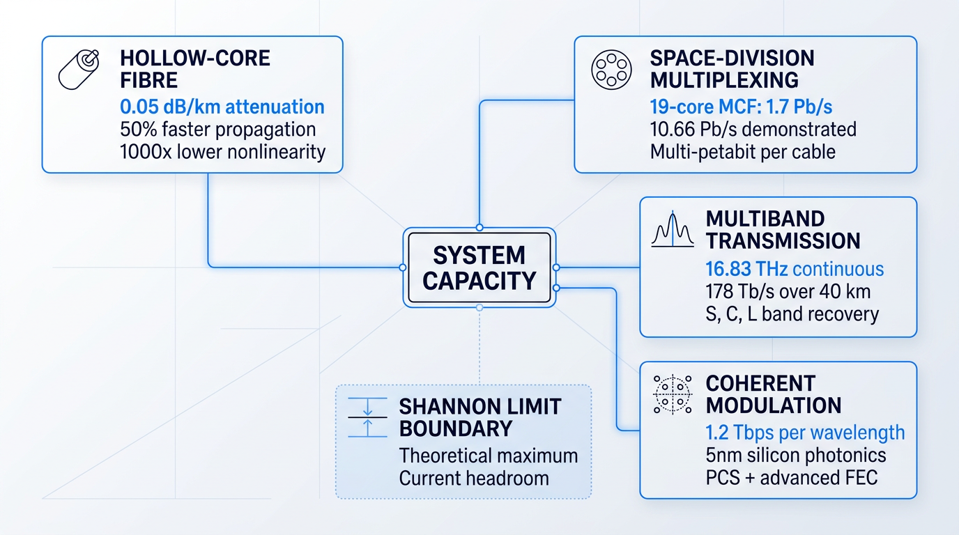
AI and data centre demand as the capacity forcing function
The engineering trends above do not exist in isolation from economic reality — they are being pulled forward by a demand signal of unusual scale and urgency. AI training and inference workloads require data movement between GPU clusters, between storage and compute, and between geographically dispersed data centres at bandwidths that dwarf conventional internet traffic. International content provider bandwidth — the category that includes hyperscalers, cloud providers, and AI platform companies — accounted for 75% of all used international capacity globally in 2025, and is forecast to increase ninefold between 2025 and 2035.
This demand is reshaping who builds the physical infrastructure of the internet. Content providers have shifted from being customers of wholesale capacity to being the dominant constructors of new submarine cable systems, either as sole owners of private cables or as majority investors in consortium builds. On trans-Atlantic routes, 100% of planned new cables are content provider-led; on trans-Pacific routes, content providers account for approximately 80% of investment.
The financial scale of the current build cycle is without modern precedent. According to TeleGeography, the value of new submarine cables planned to enter service from 2026 to 2029 exceeds $16 billion — a level of investment not seen since the telecoms boom of 2000–2001, and one that is projected to sustain at an average of $5 billion annually through 2035.
The $16 billion+ submarine cable investment cycle is not just a capacity story — it is the forcing function that determines which research directions receive commercial investment and on what schedule. HCF is being deployed for AI interconnect latency; SDM is advancing because per-cable capacity must scale; coherent technology is evolving because cost-per-bit must fall. Hyperscaler demand has compressed the gap between laboratory demonstration and commercial deployment for all three.
From the first experiments guiding light through glass to today's petabit-scale submarine systems, optical telecommunications has always advanced when the engineering constraints of one generation became the solved problems of the next. Hollow-core fibre, space-division multiplexing, multiband amplification, and coherent scaling at 1.2 Tbps and beyond represent that next generation — and with the investment now committed, the transition from research to infrastructure is already underway.
Conclusion
Optical telecommunications: the field in perspective
The distance from total internal reflection to a transoceanic cable system carrying terabits per second is enormous — yet it is a single, unbroken line of physics becoming engineering becoming infrastructure.
Optical telecommunications rewards those who understand not just the components, but the discipline of assembling them: link budgets, dispersion management, amplifier placement, and fibre selection are where systems are won or lost.
The field is still moving, and the principles covered here are the foundation for engaging with whatever capacity frontiers come next.
Frequently asked questions about optical telecommunications
Quick, self-contained answers to the questions professionals most commonly ask about optical telecommunications technology and networks.
Optical telecommunications is the transmission of information over distance using light, typically guided through glass or plastic optical fibres. Light is confined within the fibre by total internal reflection — the physical principle that causes light to bounce along the fibre core rather than escape through the cladding. This technology forms the backbone of modern global communications infrastructure. Optical fibre now carries the vast majority of the world's digital data, spanning subsea cables connecting continents, long-haul terrestrial backbone networks, and access networks delivering broadband to homes and businesses.
The primary distinction is core diameter: single-mode fibre has a core of approximately 8–10 µm, while multimode fibre has a core of 50 µm or 62.5 µm. Single-mode supports only the fundamental propagation mode, eliminating intermodal dispersion and enabling far superior bandwidth over long distances. Multimode supports many modes simultaneously, which limits its usable bandwidth-distance product. Single-mode achieves significantly lower attenuation than multimode, making it the choice for long-haul, metro, and high-capacity links. Multimode is well suited to shorter connections within data centres and enterprise campus environments, where its lower transceiver cost offsets its bandwidth limitations.
Dense Wavelength Division Multiplexing (DWDM) is a technique that transmits multiple optical channels simultaneously on a single fibre, each at a slightly different wavelength. Rather than upgrading physical infrastructure, operators multiply capacity by adding more wavelength channels to the same fibre strand. The ITU-T G.694.1 standard defines narrow channel grids across the C-band (1530–1565 nm), enabling tens of channels — commonly 40 to 80 or more — to coexist on a single fibre. Erbium-doped fibre amplifiers (EDFAs) are essential to DWDM's practicality: they amplify all wavelengths simultaneously within the C-band without converting signals to electrical form, making long-haul DWDM economically viable. Extending operation into the L-band (1565–1625 nm) alongside the C-band — known as C+L band operation — is a further capacity lever, effectively doubling the number of available channels on a single fibre.
The principal downside is the high upfront cost and complexity of physical deployment. Civil works — trenching, ducting, and securing right-of-way — represent the dominant share of total fibre deployment capital expenditure, making fibre rollout significantly more expensive than upgrading copper or deploying wireless infrastructure. Multi-jurisdiction permitting and right-of-way negotiations can add months or years to project timelines, and skilled installation and splicing labour is in short supply in many markets. For consumers, the practical consequence is limited availability in rural and low-density areas, where deployment costs are hardest to recover. Installation can also cause temporary disruption to roads and properties. Once deployed, however, fibre offers superior long-term economics, performance, and longevity compared to copper or wireless alternatives. The downside is front-loaded capital and complexity — not ongoing performance.
Signal loss — formally called attenuation — in optical fibre arises from two intrinsic mechanisms. Rayleigh scattering dominates at shorter wavelengths: it is caused by microscopic density fluctuations frozen into the glass during manufacture, and scales with wavelength as 1/λ⁴. Infrared absorption dominates at longer wavelengths, arising from molecular vibration in the silica lattice. Extrinsic contributors add further loss: OH⁻ ion absorption creates a pronounced water peak in the 1380–1390 nm region; transition-metal impurities scatter and absorb light; and bending losses — both macrobending from cable routing and microbending from physical stress or poor installation — can be significant in practice. The 1550 nm transmission window is preferred precisely because it sits at the minimum of the combined intrinsic loss curve, where standard single-mode fibre achieves its lowest attenuation values.
There is no single answer — unamplified reach is a system design question governed by the link budget: transmitter launch power, fibre attenuation, splice and connector losses, and receiver sensitivity all interact to set the practical limit. For standard single-mode fibre operating at 1550 nm, signal power typically falls below the receiver's sensitivity threshold after a few tens of kilometres. In long-haul DWDM systems, EDFAs or electronic regenerators are therefore required at regular intervals to restore signal power across extended distances. Shorter-reach applications operate comfortably without amplification: enterprise campus and data centre interconnect links commonly span a few kilometres, and PON access networks routinely reach approximately 20 km from the central office to the subscriber without any amplification at all.
Coherent optical transmission is a detection technique that encodes information in the amplitude, phase, and polarisation of the optical carrier — rather than just its intensity, as in traditional on-off keying. By exploiting all four dimensions of the optical field, coherent systems achieve far greater spectral efficiency and support per-wavelength capacities of 400G, 800G, and beyond. Coherent receivers use a local oscillator laser paired with digital signal processing (DSP) to decode the full optical field. The DSP also compensates electronically for chromatic dispersion and polarisation mode dispersion, removing the need for physical dispersion-compensating fibre in many deployments. Higher-order modulation formats — DP-QPSK, 16QAM, 64QAM — trade spectral efficiency against reach, and operators select the appropriate format based on each link's capacity-reach requirement. Coherent technology has evolved through successive generations, from early 100G commercial deployments through to 400G, which is now mainstream, with 800G systems in active development and deployment.