

Introduction
Optical fibres are already at work around you — carrying the broadband signal feeding your screen, threading through an endoscope in a hospital, and monitoring the structural health of bridges and pipelines.
What makes them so widely relied upon comes down to physics, materials science, and precision engineering working together in a strand thinner than a human hair.
This guide moves from the physical structure of a single fibre, through the science that keeps light trapped inside it, through fibre types and real-world performance, and out to the applications and emerging developments that depend on all of it.
Whether you're a student, an engineer, or simply curious, each section builds naturally on the last — no prior knowledge required, no need to look elsewhere.
TL;DR
Optical fibres are far more than a faster alternative to copper wire. Their physical properties — guiding light with minimal loss, immune to electromagnetic interference, scalable to extraordinary bandwidths — make them the foundational medium for modern communications, medical imaging, industrial sensing, and scientific instrumentation alike.
This article covers:

Optical fibre physical structure and light guidance
Single-mode, multimode, and specialty fibre types
Technical performance: attenuation, dispersion, and bandwidth
Applications across telecommunications, medicine, sensing, and industry
Optical fibre vs. copper and installation challenges
What Are Optical Fibres?
The broadband cable feeding your router, the thin illuminated strands in a decorative lamp, the slender probe a surgeon guides through a patient's body — all of these rely on the same fundamental technology: a strand of transparent material so precisely engineered that it can carry light from one end to the other with almost no loss along the way.
An optical fibre is a thin, flexible strand of highly transparent material — typically silica glass or, in some applications, polymer plastic — designed to act as a waveguide for light. Unlike a copper wire, which carries electrical current, or a structural cable, which bears mechanical load, an optical fibre has one purpose: to guide light from point A to point B with minimal loss. Fibres made from silica glass dominate telecommunications and industrial uses; those made from plastic, known as plastic optical fibre (POF), serve shorter-range, lower-cost applications.
The Three-Layer Structure
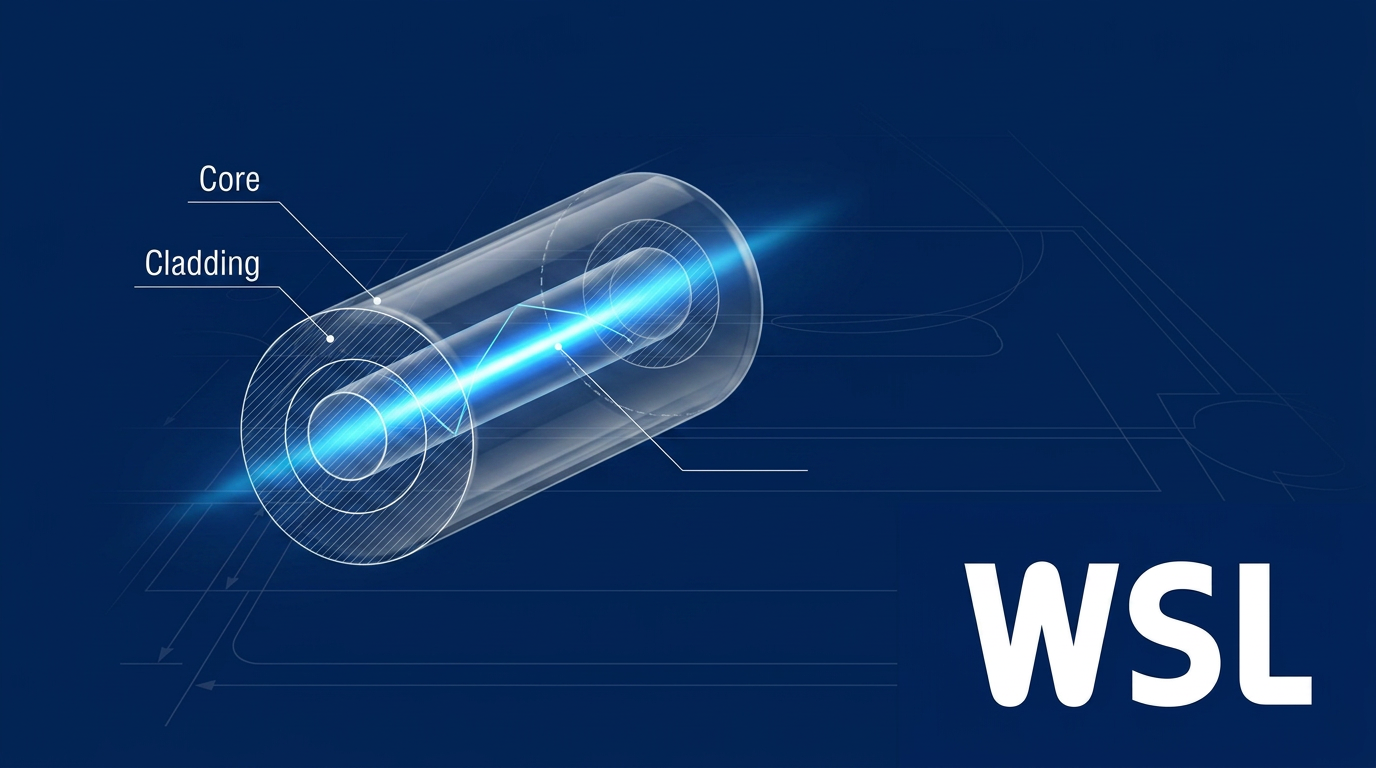
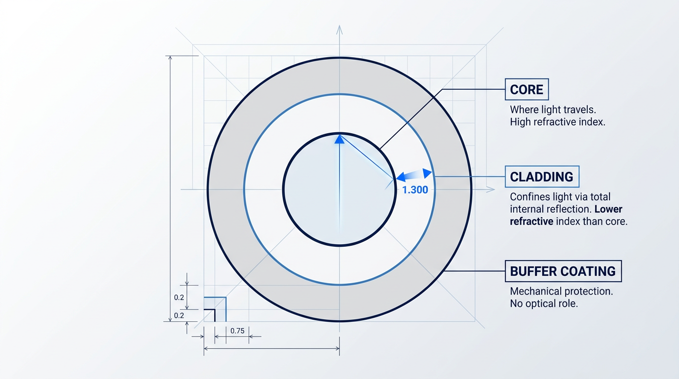
Every optical fibre is built from three concentric layers, each serving a distinct and necessary role. Stripping away any one of them would either destroy the fibre's ability to guide light or leave the glass vulnerable to damage.
- Core: The innermost region, where light actually travels. Made of highly transparent glass or plastic with a relatively high refractive index.
- Cladding: Surrounds the core with a slightly lower refractive index. This small difference is what confines light inside the core rather than letting it escape.
- Buffer Coating: An outer plastic jacket providing mechanical protection against abrasion, moisture, and handling. It plays no optical role whatsoever.
It is worth pausing on the cladding, because it is easy to mistake it for a passive sleeve. In fact, the cladding is an active optical component: without its carefully controlled refractive index — held slightly lower than the core's — light would simply leak out through the sides of the fibre rather than being guided along it.
The refractive index of a material is a measure of how much it slows light down relative to its speed in a vacuum: the higher the index, the more slowly light travels through that material. The core is formulated to have a slightly higher refractive index than the cladding, and it is this contrast — small but precise — that creates the optical boundary making light guidance possible.
The refractive index difference between the core and cladding of a typical silica fibre is very small — a fraction of a percent — yet this fractional contrast is sufficient to trap light entirely within the core, preventing it from escaping through the sides across kilometres of fibre.
This trapping mechanism is called total internal reflection (TIR). When a ray of light travelling through the core strikes the core-cladding boundary at a sufficiently shallow angle, it bounces back into the core rather than passing through into the cladding. The fibre acts as a flexible light pipe: light zigzags along the core, reflecting off the boundary repeatedly, travelling from one end of the fibre to the other.
To appreciate the precision involved, consider the physical scale. A complete optical fibre is roughly the diameter of a human hair, yet the layers within it are engineered to tolerances measured in micrometres. The core diameter varies significantly by fibre type: single-mode fibres, designed to carry a single ray of light, have very narrow cores; multimode fibres, which carry multiple light paths simultaneously, have considerably wider ones. This difference in core size is the foundation for understanding why the two fibre types behave so differently — a distinction explored fully in a later section.
One distinction worth establishing now: a single optical fibre is not the same as an optical fibre cable. A cable is the deployable assembly — multiple individual fibres bundled together with strength members and an outer protective jacket — that is actually laid in the ground, pulled through conduit, or strung across ocean floors.
With the structure, materials, and guiding mechanism established, the natural next question is: how exactly does total internal reflection work, and what determines whether light stays inside the fibre or escapes? The next section examines the underlying physics in full.
How Total Internal Reflection Works
Light travels in straight lines — so what keeps it trapped inside a hair-thin strand of glass that can bend, coil, and run for kilometres? The answer is a precise optical phenomenon that turns the glass-cladding boundary into a perfect mirror, and it begins with a rule that governs every boundary between two transparent materials.
Snell's law describes what happens when a ray of light crosses from one medium into another with a different refractive index: the ray changes direction at the boundary, a process called refraction. The direction of that bend depends on which way the refractive index changes.
When light moves from a denser medium (higher refractive index) into a less dense one (lower refractive index), it bends away from the normal — the imaginary line perpendicular to the surface at the point of entry. Intuitively, the light speeds up as it enters the less dense medium, causing the wavefront to pivot outward, so the transmitted ray angles further from perpendicular than the incoming ray.
The Critical Angle and Total Internal Reflection
As the angle of incidence increases — that is, as the incoming ray strikes the boundary at a shallower and shallower angle relative to the normal — the refracted ray bends further and further away from the normal on the other side. There is a specific angle at which the refracted ray no longer passes through into the less dense medium at all: it travels exactly along the boundary, at 90° to the normal. That angle is the critical angle.
The critical angle is not arbitrary — it is set by the ratio of the two refractive indices, derived directly from Snell's law. A larger contrast between the two indices produces a lower critical angle, making the threshold easier to reach. In a typical silica optical fibre, the refractive index difference between core and cladding is less than 1%, which places the critical angle very close to 90° — meaning light must travel nearly parallel to the fibre axis to satisfy the condition.
At any angle of incidence below the critical angle, refraction occurs and some light escapes into the cladding. At the critical angle and beyond, no refracted ray exists: every photon is reflected back into the core. This is total internal reflection (TIR) — and unlike ordinary partial reflection, it is theoretically lossless.
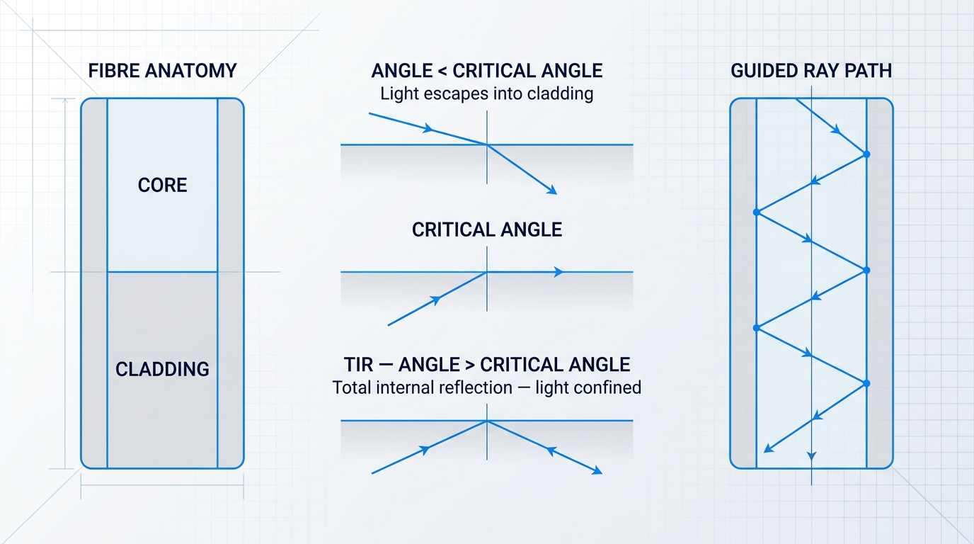
In an optical fibre, light injected into the core travels at a shallow angle to the fibre axis and repeatedly strikes the core-cladding interface as it propagates forward. Provided each strike occurs at an angle greater than the critical angle, the light is reflected back into the core and continues onward — bouncing in a zig-zag (or, for off-axis rays, a helical) path along the entire length of the fibre.
The practical significance of TIR being lossless is enormous. Partial reflection — what occurs below the critical angle — allows some light to escape at every bounce; over thousands of bounces per metre, the cumulative loss would be catastrophic. TIR retains essentially all the light at each reflection, which is precisely what makes optical fibres viable for transmitting signals over long distances.
The Acceptance Cone and Numerical Aperture
TIR only works if the light inside the core is actually striking the interface at an angle above the critical angle. That condition places a constraint on how light can be fed into the fibre in the first place: rays entering the end face at too steep an angle — too far from the fibre axis — will hit the core-cladding boundary at an angle below the critical angle and leak straight out into the cladding.
The range of input angles for which TIR is maintained throughout the fibre defines the acceptance cone: a cone of directions, centred on the fibre axis, within which incoming light will be successfully guided. Light arriving from outside this cone is not guided and is lost.
The numerical aperture (NA) is the quantitative expression of the acceptance cone. It is a dimensionless number equal to the sine of the half-angle of the cone, and it is determined entirely by the refractive indices of the core and cladding. A higher NA corresponds to a wider acceptance cone — the fibre gathers light more easily and tolerates a broader range of input angles.
Higher NA also means that more distinct propagation paths — more modes — can satisfy the TIR condition simultaneously. The NA is therefore a key specification: it tells you both how easy it is to couple light into the fibre and how many propagation modes the fibre can support, which has direct consequences for bandwidth.
Why the Cladding Does More Than Lower the Index
TIR depends entirely on the integrity of the core-cladding interface. Consider what would happen with a bare glass core and no cladding: the interface would exist between the glass and whatever happens to surround it — air in an ideal laboratory setting, but in practice dust, oils, fingerprints, moisture, or physical abrasions.
Any contamination at that interface alters the local refractive index in an uncontrolled way. Where the refractive index contrast is disrupted, the critical angle condition may no longer be met, and light leaks out at that point. Over the full length of a fibre, even microscopic surface irregularities would cause cumulative losses that make the fibre useless.
The cladding solves this by providing a precisely controlled, uniform material with a known refractive index across the entire length of the fibre. It is not a passive structural shell — it is the active guardian of the optical interface, ensuring that the refractive index contrast the fibre was designed for is maintained consistently from end to end.
The refractive index difference between core and cladding in a typical silica fibre is less than 1% — yet this small contrast is sufficient to confine light with near-total efficiency over kilometres. The reason is that TIR, unlike partial reflection, loses essentially nothing at each bounce. Thousands of reflections per metre accumulate no meaningful loss, provided the interface remains clean and the critical angle condition is met.
Bend radius limits follow directly from the same geometry. When a fibre is bent, the angle at which a guided ray strikes the core-cladding interface changes: on the outside of the curve, the effective angle of incidence decreases. At a sharp enough bend, rays that were comfortably above the critical angle now fall below it — and light escapes into the cladding at that point.
The tighter the bend, the more propagation modes are pushed below the critical angle threshold and the more light is lost. This is the physical origin of the minimum bend radius specification that every optical fibre carries — a constraint that flows directly from TIR geometry rather than from mechanical fragility alone. The practical implications, including specific bend radius values and bend-insensitive fibre designs, are covered in the installation and maintenance section later in this guide.
With TIR established as the guiding mechanism, the next question is how a fibre is actually built to exploit it — specifically, how manufacturers engineer the precise refractive index contrast between core and cladding that makes the whole system work.
How Optical Fibres Are Made
A finished optical fibre is thinner than a human hair, yet its optical properties are engineered to tolerances measured in nanometres — the refractive index difference between core and cladding precisely controlled, the glass so pure that light can travel kilometres before losing even a fraction of its power. That level of precision does not emerge from ordinary glassmaking. It is the product of a manufacturing chain that begins with ultra-pure chemistry and ends with a coated strand ready to carry data across continents.
Why Ultra-Pure Silica Glass
The starting material for virtually all telecommunications-grade optical fibre is fused silica — amorphous silicon dioxide (SiO₂) of extraordinary purity, quite different from the silica in ordinary window glass.
Purity governs performance directly: impurities in the glass, particularly hydroxyl (OH) ions absorbed during manufacture, create absorption peaks that consume light at specific wavelengths, while microscopic density variations in the amorphous structure cause Rayleigh scattering, deflecting light out of the core.
These density fluctuations are unavoidable to some degree — they are effectively frozen into the glass at the high temperatures of the drawing process — but controlling impurity levels to below parts-per-billion concentrations is what allows modern single-mode silica fibre to achieve attenuation as low as approximately 0.2 dB/km near 1550 nm, approaching the fundamental physical limit set by Rayleigh scattering itself.
This extraordinary transparency is what makes kilometre-scale transmission possible: the light that total internal reflection keeps bouncing along the core must survive the journey, and that survival depends entirely on the purity of the material it travels through.
The Preform: Engineering at Scale
The central object of fibre manufacturing is the preform — a solid glass rod, typically around 1 metre long and 2 cm or more in diameter, whose cross-section encodes the complete optical design of the finished fibre at a scale hundreds of times larger.
The logic of starting large is precision: achieving a specific refractive index profile across a core just 8–50 µm wide is far easier when you first build it at centimetre scale and then draw it down proportionally, preserving every ratio in the geometry as the glass narrows.
Three principal methods are used to build preforms, all based on controlled chemical vapour deposition of silica and dopant compounds, layer by layer, to construct the desired refractive index profile from the inside out or outside in.
- MCVD: Modified Chemical Vapour Deposition deposits doped silica glass layers inside a rotating silica tube, using an external traversing torch to drive the chemical reactions.
- OVD: Outside Vapour Deposition builds up layers of glass soot on the outside of a rotating mandrel; the mandrel is removed and the porous soot body is dried and sintered into solid glass.
- VAD: Vapour Axial Deposition deposits glass along the preform's axis, enabling continuous production and making it well-suited to high-volume manufacturing.
Each method achieves the same fundamental outcome: a glass rod whose radial composition profile will become the fibre's optical architecture once drawn.
Dopants and Refractive Index Engineering
The refractive index difference between core and cladding — the physical condition that total internal reflection depends on — is not an intrinsic property of silica itself; it is engineered into the glass through precise dopant chemistry.
- Germanium dioxide (GeO₂): Raises the refractive index of silica. Added to the core region to create the higher-index waveguide that confines light through total internal reflection.
- Fluorine: Lowers the refractive index of silica. Used in the cladding to depress the index below the undoped silica baseline, increasing the core-cladding contrast.
The concentration gradient of these dopants across the preform cross-section determines not just the magnitude of the index difference but its shape — whether the index steps abruptly from core to cladding (step-index) or grades smoothly from the centre outward (graded-index).
This is the manufacturing mechanism behind the fibre type distinctions the next section will explore: the dopant profile written into the preform during deposition is precisely what distinguishes a single-mode step-index fibre from a multimode graded-index fibre before a single millimetre of fibre has been drawn.
The Drawing Tower
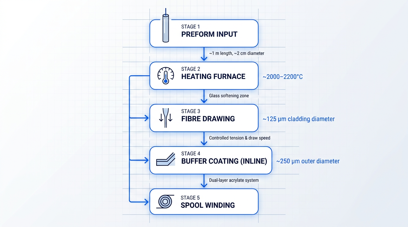
Once the preform is complete, it is loaded into a drawing tower — a precision apparatus several metres tall — where its lower tip is fed into a furnace operating at approximately 2,000–2,200°C.
At that temperature the glass softens, and a thin strand is drawn downward under controlled tension, cooling rapidly into a fibre of ~125 µm cladding diameter — the standard for all telecommunications-grade silica fibre.
Draw speed and furnace temperature are controlled with high precision: variations in either translate directly into diameter fluctuations, which produce signal loss and connector alignment problems in the finished fibre.
Immediately after drawing, a buffer coating — typically a dual-layer acrylate system — is applied inline before the bare glass contacts any surface, protecting the pristine glass from abrasion and moisture that would degrade its mechanical strength; the coated fibre typically reaches an outer diameter of around 250 µm.
Plastic Optical Fibre: A Different Material Family
Plastic optical fibre (POF) is not a budget substitute for silica — it is a fundamentally different engineering trade-off, built from transparent polymer materials with a distinct set of performance characteristics suited to a different class of applications.
The most common form uses a PMMA (polymethyl methacrylate) core with a fluorinated polymer cladding; like silica fibre, total internal reflection at the core-cladding boundary confines the light, but the optical and mechanical properties of the two material systems diverge sharply.
| Property | Step-Index PMMA POF | Single-Mode Silica Fibre |
|---|---|---|
| Core diameter | ~1 mm (1000 µm) | ~8–10 µm |
| Cladding diameter | ~1 mm total (plastic cladding) | 125 µm |
| Attenuation | ~150–200 dB/km at 650 nm | ~0.2 dB/km at 1550 nm |
| Practical link distance | ~50–100 m | Tens to hundreds of kilometres |
| Termination method | Cleave and polish; no fusion splicing | Fusion splicing or precision connectors |
| Mechanical flexibility | High; not brittle | Brittle; requires careful handling |
Direct comparison of key specifications between step-index PMMA POF and standard single-mode silica fibre, illustrating the material trade-offs that determine where each is used.
The attenuation gap is stark: POF loses roughly 1,000 times more signal per kilometre than single-mode silica, which is why practical POF links are limited to roughly 50–100 metres.
Step-index PMMA POF exhibits attenuation of approximately 150–200 dB/km, compared to ~0.2 dB/km for standard single-mode silica at 1550 nm — a difference of roughly three orders of magnitude that caps practical POF link lengths at around 50–100 metres.
Within that short-range envelope, however, POF's large core diameter makes it highly tolerant of mechanical misalignment, its polymer construction means it can be terminated with a sharp knife and simple polish rather than fusion splicing equipment, and its flexibility without brittleness makes it practical in environments where glass would be a liability.
These properties explain its established presence in home audio digital links (TOSLINK/S/PDIF), automotive multimedia networks (the MOST bus), and short industrial control links — applications where installation simplicity and low connector cost outweigh any need for long reach.
Cable Construction: From Strand to Deployable Cable
A coated fibre strand, however pure and precisely drawn, is not yet a cable — it is fragile glass that would fail under the tensile loads of installation and the environmental stresses of a deployed network.
Strength members — typically aramid yarn (sold under the brand name Kevlar) or fibreglass epoxy rods — are incorporated into the cable structure to carry mechanical tension during pulling and installation, keeping the glass itself free from tensile stress.
The buffer configuration chosen around each fibre determines the cable's environmental suitability: in loose-tube construction, fibres float freely in a gel-filled plastic tube that accommodates thermal expansion and provides moisture protection, making it the standard for outdoor and direct-burial cables; in tight-buffer construction, a thick plastic layer is extruded directly over the fibre coating, producing a more rugged and handleable structure suited to indoor riser and distribution cables.
The outer jacket material is selected for the deployment environment: PVC for general indoor use, polyethylene for outdoor exposure, and steel or aluminium armour for direct-burial or rodent-prone environments where the cable must resist mechanical damage from outside.
With the manufacturing chain complete — from ultra-pure silica chemistry through preform deposition, drawing, coating, and cable assembly — the differences between fibre types become visible as deliberate choices made at each stage: the dopant profiles and core dimensions established in the preform are precisely what separate single-mode from multimode fibre, and step-index from graded-index designs, as the next section explores.
What Are the Different Types of Optical Fibre?
Not all optical fibres are the same — and that is precisely the point. The diversity of fibre types reflects the diversity of what light-based technology needs to do: carry a signal across an ocean, link servers inside a data centre, deliver a surgical laser to tissue, preserve a polarisation state for an inertial navigation system. Each architecture is an engineering answer to a specific set of constraints, and understanding those answers is what makes the fibre type landscape coherent rather than confusing.
Single-Mode Fibre
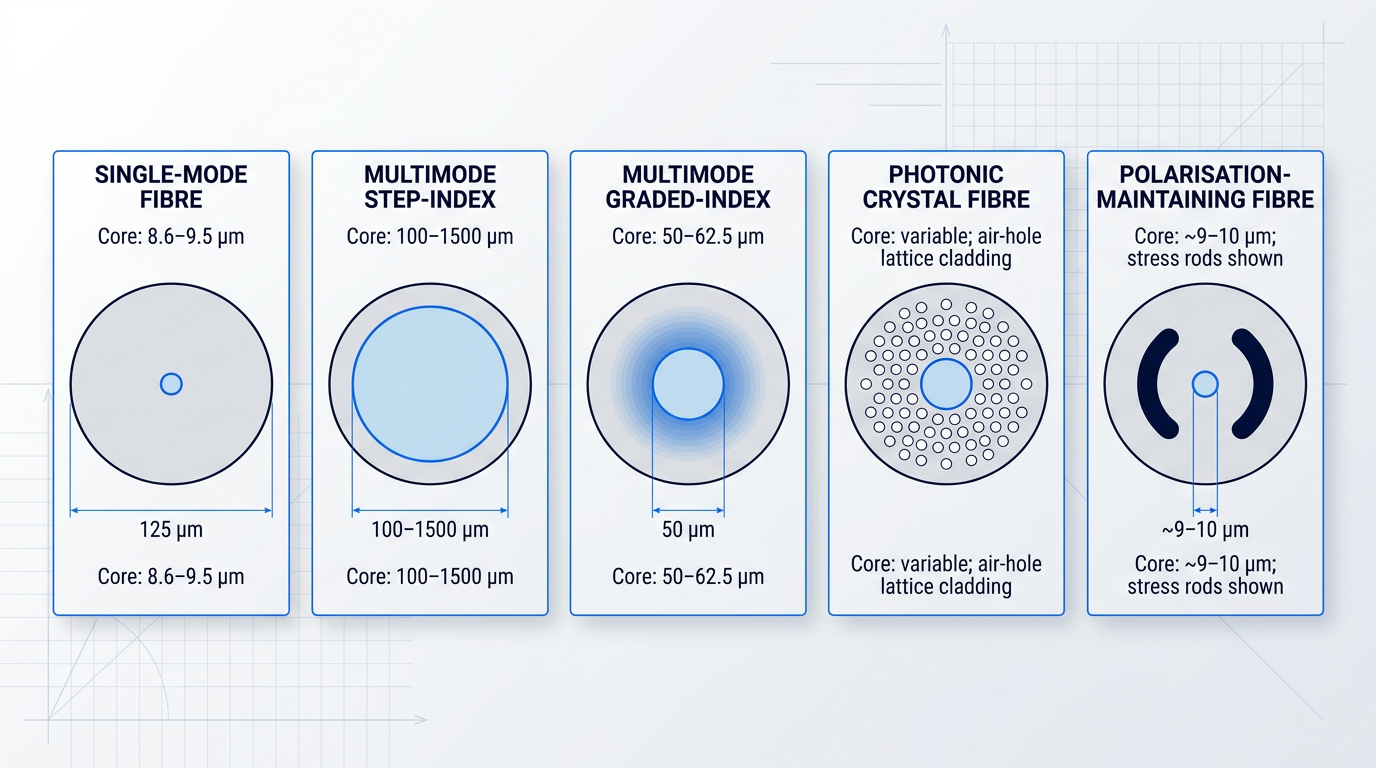
Single-mode fibre (SMF) has a very small core — the ITU-T G.652 standard, the most widely deployed SMF specification, defines a mode field diameter in the range of 8.6–9.5 µm at 1310 nm, with a cladding diameter of 125 µm.
That narrow core supports only a single propagation mode, which eliminates intermodal dispersion entirely: there are no competing ray paths to arrive at different times and spread the pulse.
Without intermodal dispersion, very high bandwidth signals can travel very long distances without pulse spreading — which is why SMF dominates long-haul telecommunications, submarine cables, and metropolitan backbone networks where distance is the primary constraint.
Multimode Step-Index Fibre
Step-index multimode fibre takes the opposite approach: a large core with a refractive index that remains constant across its full width, then drops abruptly at the core-cladding boundary.
That abrupt index change means many propagation modes are supported, each travelling a different path through the core and arriving at slightly different times — a phenomenon known as intermodal dispersion that limits both bandwidth and usable distance.
Step-index multimode fibres are available in core sizes ranging from 100 to 1500 µm, and that large core is a genuine engineering advantage for applications where power delivery matters more than bandwidth: the wide aperture is easy to couple light into, tolerates high optical power, and offers a high numerical aperture for efficient light collection.
Industrial laser delivery and medical laser procedures — where kilowatts of optical power must reach a target with minimal coupling loss — are the natural home for step-index multimode fibre, as will be explored in later sections on applications.
Multimode Graded-Index Fibre
Graded-index multimode fibre solves the intermodal dispersion problem of step-index designs by engineering a core whose refractive index decreases gradually from the centre outward, rather than dropping abruptly at the boundary.
This graduated profile — achieved through a precisely controlled dopant concentration gradient during manufacture, as established in the previous section — causes light rays to follow curved, sinusoidal paths that continuously refocus towards the axis, equalising mode arrival times and dramatically reducing intermodal dispersion.
The standard core sizes are 50 µm and 62.5 µm, both with a 125 µm cladding diameter — a geometry common across the industry and confirmed by Corning and Thorlabs product specifications.
In practice, graded-index multimode fibre is specified for data centre and enterprise network use through the OM-grade classification system: OM3 fibre delivers a minimum effective modal bandwidth (EMB) of 2000 MHz·km at 850 nm, supporting 10 Gigabit Ethernet to 300 m; OM4 doubles that to 4700 MHz·km EMB, reaching 400 m at 10G and 150 m at 40/100G; and OM5, approved by ISO/IEC in 2016, adds bandwidth characterisation at 953 nm to support short wavelength division multiplexing (SWDM) for 40G and 100G applications.
Graded-index multimode fibre dominates data centre interconnects because it combines adequate bandwidth at short distances with a significant cost advantage: multimode transceivers use VCSELs (vertical-cavity surface-emitting lasers) at 850 nm, which are substantially less expensive than the single-mode transceivers required for SMF links, making it the optimal choice for the short reaches typical of most data centre deployments.
Photonic Crystal Fibre
Photonic crystal fibre (PCF) departs from the conventional core-cladding architecture entirely: instead of a solid glass cladding with a slightly different refractive index, PCF has a microstructured cladding of air holes running along the full length of the fibre, forming a two-dimensional periodic lattice.
Two distinct guidance regimes exist within this family. In index-guiding PCF, the solid silica core is surrounded by the air-hole lattice, which reduces the effective refractive index of the cladding below that of the core — enabling total internal reflection by the same mechanism covered in §4, but with a structure that can be tuned in ways impossible with conventional fibre.
The hole size, spacing, and lattice geometry can be adjusted independently to achieve properties including endlessly single-mode behaviour across a very wide wavelength range (from the ultraviolet to the infrared), tunable dispersion, and very high or very low optical nonlinearity depending on design.
The second sub-type, hollow-core PCF, guides light through a central air channel via a photonic bandgap mechanism — the periodic air-hole cladding creates a two-dimensional photonic crystal structure that forbids light at certain frequencies from propagating laterally, trapping it in the hollow core. This is a fundamentally different confinement mechanism from total internal reflection, making hollow-core PCF the notable exception to the TIR-based guidance rule.
PCF's engineering value lies in enabling optical properties simply not achievable in conventional glass fibre; its hollow-core variant in particular is a topic of active development, with implications for future communications and sensing that will be explored in the later section on trends.
Polarisation-Maintaining Fibre
In a standard single-mode fibre, the polarisation state of light drifts unpredictably as it travels: bending, temperature changes, and mechanical stress all perturb the polarisation, making it impossible to deliver a known, stable polarisation state at the output.
Polarisation-maintaining fibre (PMF) solves this by introducing a large, deliberate birefringence into the fibre structure — a significant refractive index difference between two orthogonal propagation axes, which suppresses coupling between polarisation modes and locks light launched along one axis into that state.
The birefringence is created through stress-applying elements embedded in the cladding during manufacture. The two dominant designs are PANDA fibre, which uses two cylindrical stress rods placed symmetrically beside the core, and bow-tie fibre, which uses wedge-shaped stress regions; in both cases, the rods contract more than the surrounding cladding as the fibre cools after drawing, placing the core under asymmetric tension and creating two distinct propagation axes with different effective refractive indices.
The applications that depend on PMF are those where polarisation fidelity is the primary engineering constraint: fibre optic gyroscopes (which detect rotation via the Sagnac effect and require a stable polarisation state throughout the sensing coil), coherent optical communications, quantum key distribution using polarisation-encoded photons, and interferometric sensors.
Comparing Fibre Types at a Glance
The table below summarises the five fibre types across the dimensions that define their engineering role, drawing on ITU-T, Corning, Thorlabs, Newport, and IEEE source data.
| Fibre Type | Typical Core Diameter | Guidance Mechanism | Key Optical Property | Primary Application Domain |
|---|---|---|---|---|
| Single-mode (SMF) | 8.6–9.5 µm mode field diameter (ITU-T G.652) | Total internal reflection | Zero intermodal dispersion; supports very long distances | Long-haul telecoms, submarine cables, metropolitan backbone |
| Multimode step-index | 100–1500 µm | Total internal reflection | High intermodal dispersion; high numerical aperture; high power tolerance | Industrial and medical laser power delivery |
| Multimode graded-index | 50 µm or 62.5 µm (cladding 125 µm) | Total internal reflection | Reduced intermodal dispersion via parabolic index profile; OM3/OM4/OM5 grades | Data centre interconnects, enterprise LANs (short-reach high-speed links) |
| Photonic crystal (PCF) | Solid core: variable; hollow core: air channel | Index guiding (solid-core) or photonic bandgap (hollow-core) | Endlessly single-mode; tuneable dispersion; very high or low nonlinearity | Nonlinear optics, supercontinuum generation, specialised sensing, future low-latency links |
| Polarisation-maintaining (PMF) | Single-mode core (e.g. ~9–10 µm at 1310/1550 nm) | Total internal reflection with stress-induced birefringence | Stable linear polarisation state over full fibre length | Fibre optic gyroscopes, coherent comms, quantum key distribution, interferometric sensors |
Side-by-side comparison of the five optical fibre types by core diameter, guidance mechanism, key optical property, and primary application domain.
The most striking pattern in this landscape is the enormous range of core diameters — from under 10 µm for single-mode fibre to over a millimetre for some step-index power delivery fibres — which directly reflects the diversity of optical tasks being solved.
Guidance mechanism also varies more than is often appreciated: four of the five types rely on total internal reflection, but hollow-core PCF breaks that rule entirely, confining light in air through photonic bandgap effects rather than through glass refractive index contrast.
The right fibre is always the one matched to the application's dominant constraint. Single-mode for distance and bandwidth. Graded-index multimode for cost-effective short-range high-speed links. Step-index multimode for power delivery. PCF and PMF where conventional fibres cannot meet the optical requirement. Choosing by application, not by perceived sophistication, is how engineers actually specify fibre.
Understanding which fibre type is in use is the essential prerequisite for interpreting its performance — because attenuation figures, dispersion behaviour, and bandwidth limits are all fibre-type-specific. The next section examines exactly those characteristics: how each fibre type performs in terms of signal loss, pulse spreading, and usable bandwidth.
Attenuation, Dispersion, and Bandwidth Explained
Knowing what type of optical fibre you have tells you relatively little on its own. What actually determines whether a fibre is fit for purpose in a given deployment are three measurable performance parameters: attenuation, dispersion, and bandwidth. These are the numbers engineers reach for when deciding whether single-mode fibre will carry a signal across a continent, or why graded-index multimode fibre is the right choice for a data centre floor.
Attenuation: Why Signals Fade Over Distance
Attenuation is the loss of optical power as light travels along the fibre, measured in decibels per kilometre (dB/km). It sets the distance ceiling: how far a signal can propagate before it falls below the receiver's sensitivity threshold and requires amplification or regeneration.
The dominant intrinsic cause is Rayleigh scattering — the scattering of light by microscopic density fluctuations frozen into the silica glass during manufacture. These fluctuations are smaller than the wavelength of light, and the scattering they produce is inversely proportional to the fourth power of wavelength. Double the wavelength and scattering falls by a factor of sixteen. This is the fundamental physical reason why longer wavelengths are preferred for long-distance transmission.
The second intrinsic cause is absorption by impurities in the glass, particularly hydroxyl (OH) groups introduced as water contamination during manufacturing. These create strong absorption peaks at specific wavelengths — most notably around 1383 nm, which historically blocked use of the E-band entirely. Modern ultra-dry fibres compliant with ITU-T G.652.D have largely eliminated this water peak: the standard requires that attenuation at 1383 nm be no greater than the maximum specified for the 1310–1625 nm range after hydrogen ageing.
Extrinsic causes — macrobending (sharp bends that cause light to leak from the core) and microbending (microscopic lateral stresses from cabling or environmental pressure) — also contribute to loss, but these are installation and cabling considerations rather than intrinsic fibre properties, and are addressed separately.
Wavelength Windows: Where Loss Is Minimised
Because attenuation is so strongly wavelength-dependent, telecom systems are designed to operate in the spectral windows where loss reaches its lowest values. Three windows dominate practical deployment.
At 850 nm, attenuation is relatively high — around 3 dB/km for multimode fibre. Yet this window is standard for short-range multimode applications in data centres and LANs, because vertical-cavity surface-emitting laser (VCSEL) sources at this wavelength are inexpensive and straightforward to manufacture. When distances are short, high loss per kilometre is acceptable.
At 1310 nm, standard G.652 single-mode fibre achieves a maximum attenuation of 0.4 dB/km. Critically, this window also coincides with near-zero chromatic dispersion in G.652 fibre — a combination that makes it the preferred window for metro-area and access networks where both loss and pulse spreading must be managed.
At 1550 nm, G.652 single-mode fibre reaches its lowest attenuation: approximately 0.2 dB/km, with high-performance variants achieving 0.18 dB/km or below. This is the dominant window for long-haul and submarine systems, and the region in which erbium-doped fibre amplifiers (EDFAs) operate — a convergence that made 1550 nm the workhorse of global fibre networks.
| Fibre Type | 850 nm (dB/km) | 1300/1310 nm (dB/km) | 1550 nm (dB/km) |
|---|---|---|---|
| G.652 single-mode (standard) | — | ≤ 0.40 | ≤ 0.35 |
| G.652 single-mode (low-loss, e.g. SMF-28e+ / SMF-28 LL) | — | ≤ 0.32–0.35 | ≤ 0.18–0.20 |
| OM3 50/125 µm multimode | ≤ 3.0 | ≤ 1.5 | — |
| OM4 50/125 µm multimode | ≤ 3.0 | ≤ 1.5 | — |
Comparison of maximum attenuation at the three principal operating wavelengths across standard single-mode (G.652) and multimode (OM3/OM4) fibre types, sourced from ITU-T G.652, Corning product datasheets, and TIA-568.3-D.
The table makes the performance gap between single-mode and multimode fibre immediately clear. Multimode fibre is not designed for the 1550 nm window at all — its operating domain is 850 nm and 1300 nm, where VCSEL sources are cost-effective and distances are short. Single-mode fibre's attenuation advantage at 1550 nm, by contrast, is what makes intercontinental transmission practical: at 0.2 dB/km, a signal can travel 100 km with only 20 dB of total fibre loss before amplification.
Dispersion: The Data Rate Ceiling
Where attenuation limits how far a signal travels, dispersion limits how fast it can carry data. Dispersion is the spreading of a light pulse as it propagates along the fibre: a pulse that broadens too much overlaps with adjacent pulses, causing inter-symbol interference and capping the maximum achievable data rate.
Intermodal dispersion affects multimode fibres only. Different propagation modes travel at different velocities through the core, arriving at the receiver at slightly different times. In step-index multimode fibre, this effect is severe — the fastest axial modes and the slowest higher-order modes can differ substantially in path length, producing significant pulse broadening.
Graded-index multimode fibre largely corrects this through its parabolic refractive index profile. Modes travelling near the core axis experience higher refractive index and therefore travel more slowly, while modes taking longer outer paths experience lower index and travel faster. The two effects largely cancel, compressing the arrival-time spread dramatically — pulse broadening in graded-index fibre is typically reduced by a factor of around 100 compared with equivalent step-index multimode fibre.
Chromatic dispersion is present in all fibre types but becomes the dominant constraint in single-mode fibre, where intermodal dispersion is absent. It arises because different wavelengths within a source's spectral width travel at slightly different speeds. Two mechanisms contribute: material dispersion (the refractive index of silica glass varies with wavelength) and waveguide dispersion (the distribution of the guided mode between core and cladding also varies with wavelength). Crucially, these two components have opposite signs and partially cancel at a specific wavelength — the zero-dispersion wavelength.
In pure bulk silica, zero material dispersion occurs near 1270 nm. However, waveguide dispersion shifts the total zero-dispersion point to approximately 1310 nm in standard G.652 single-mode fibre — which is why 1310 nm became the first major telecom window. The ITU-T G.652 standard specifies the zero-dispersion wavelength as falling between 1300 nm and 1324 nm.
At 1550 nm, the preferred low-loss window, chromatic dispersion in G.652 fibre is approximately 17 ps/(nm·km) — confirmed by both the ITU-T G.652 representative link value and Corning single-mode datasheets specifying ≤ 18 ps/(nm·km) at 1550 nm. A source with a 1 nm spectral width travelling 100 km therefore accumulates around 1700 ps of pulse spreading. At data rates of 10 Gbps and above, this becomes a significant design constraint.
This tension between the low-loss window and the low-dispersion window drove the development of dispersion-shifted fibre (DSF), classified as ITU-T G.653. By modifying the waveguide geometry, DSF moves the zero-dispersion wavelength to 1550 nm, solving the dispersion problem at the lowest-loss point. However, DSF proved problematic for dense wavelength division multiplexing (DWDM) systems: near-zero dispersion at 1550 nm promotes four-wave mixing between co-propagating channels, generating crosstalk that degrades signal quality.
The practical solution was non-zero dispersion-shifted fibre (NZDSF), classified as ITU-T G.655. Rather than placing zero dispersion at 1550 nm, G.655 fibre maintains a small but deliberately non-zero dispersion coefficient throughout the C-band (1530–1565 nm), specified at an absolute value between 0.1 and 10.0 ps/(nm·km). This residual dispersion is sufficient to suppress four-wave mixing while remaining manageable with dispersion compensation — a textbook example of engineering trade-offs rather than single-parameter optimisation.
Bandwidth: How Capacity Is Expressed
For multimode fibre, capacity is quantified as a bandwidth-distance product, expressed in MHz·km or GHz·km. The product reflects a direct trade-off: a fibre rated at 500 MHz·km supports 500 MHz over 1 km, or 250 MHz over 2 km. As distance doubles, available bandwidth halves.
Modern multimode grades are defined by their effective modal bandwidth (EMB), measured with laser sources to reflect real-world VCSEL performance rather than overfilled launch conditions. OM3 fibre is specified at 2000 MHz·km EMB at 850 nm; OM4 at 4700 MHz·km; OM5 matches OM4 at 850 nm (≥ 4700 MHz·km) and adds a specification at 953 nm (≥ 2470 MHz·km) to support short-wavelength division multiplexing across the 850–940 nm range.
Single-mode fibre does not carry a bandwidth-distance product in the same sense, because there is no intermodal dispersion to limit it. Instead, single-mode capacity is bounded by chromatic dispersion — and, at very high data rates, by polarisation mode dispersion (PMD). In practice, this gives single-mode fibre vastly superior capacity for long-haul use: coherent digital signal processing and dispersion-compensating modules can manage chromatic dispersion over thousands of kilometres in ways that have no equivalent for multimode fibre.
Step-index multimode fibre has the highest intermodal dispersion and the lowest bandwidth of any common fibre type — making it unsuitable for high-speed data transmission. Yet its large core, high numerical aperture, and high power-handling capacity make it the correct engineering choice for delivering surgical or industrial laser energy. When the task is moving optical power rather than modulated data, bandwidth is completely irrelevant.
These three parameters — attenuation setting the distance ceiling, dispersion setting the data rate ceiling, and bandwidth governing short-range capacity — explain the logic behind every major fibre application covered in the next section.
Optical Fibre Applications: Communications, Medicine, and Sensing
The physics of total internal reflection, the engineering of single-mode and multimode cores, the attenuation windows at 1310 nm and 1550 nm — all of it pays off here. Optical fibres are not a single-purpose technology: they carry internet traffic across ocean floors, guide surgical lasers to tissue, and turn kilometres of buried cable into a continuous earthquake detector.
Telecommunications and Data Communications
Single-mode fibre is the physical backbone of virtually every long-haul and submarine communications network on the planet, a position it holds because its 8–10 µm core eliminates intermodal dispersion and delivers attenuation as low as 0.17 dB/km at the 1550 nm minimum-loss window.
What multiplies that capacity to extraordinary scale is Dense Wavelength Division Multiplexing (DWDM): by assigning each data channel a distinct wavelength in the C and L bands (1530–1625 nm), a single fibre strand can carry 40 channels at 100 GHz spacing, 80 channels at 50 GHz spacing, or up to 160 channels at 25 GHz spacing — each channel running at 100 or 400 Gbit/s, giving aggregate capacities exceeding 10 Tbit/s per fibre in deployed systems.
The practical result is visible in today's submarine cable infrastructure: the Pacific Light Cable Network, for example, carries a nominal capacity of 24,000 Gbit/s across six fibre pairs spanning 13,000 km, and laboratory demonstrations using extended spectral bands have pushed single-fibre throughput past 178 Tbit/s.
- Long-haul backbone: Single-mode fibre spans continents and ocean floors, exploiting the 1550 nm attenuation window and DWDM to carry terabits per second over thousands of kilometres.
- FTTH/FTTP broadband: GPON (ITU-T G.984) delivers fibre to the home via passive optical splitters serving 16–64 subscribers from a single feeder fibre, with downstream rates up to 2.4 Gbit/s.
- Data centre interconnects: OM3/OM4/OM5 multimode fibre dominates short-reach links (up to 150 m) where low-cost VCSEL transceivers make multimode the most cost-effective choice at 40/100/400G.
- 5G fronthaul and backhaul: Dense small-cell deployments connect remote radio heads to centralised baseband pools via single-mode fibre, meeting the 50–250 µs round-trip latency budget 5G NR requires.
The data centre case deserves a closer look: as established when covering fibre types, OM3/OM4/OM5 graded-index multimode fibres are optimised for 850 nm VCSEL sources, and Corning's own cost analysis confirms that multimode 400G SR8 delivers a 20%+ cost benefit over single-mode solutions for enterprise data centres where 90–95% of links are under 100 m.
For 5G, the architecture makes fibre indispensable: centralised baseband processing (C-RAN) separates the remote radio head at the antenna from the baseband unit pool, and the fronthaul link between them must carry digitised radio signals at 10–25 Gbit/s per cell with latency measured in tens of microseconds — a requirement that fibre's low latency, high capacity, and immunity to electromagnetic interference satisfy where no other medium at scale can.
Medical Applications of Optical Fibres
Yes — endoscopy uses optical fibres, and has done so since Basil Hirschowitz at the University of Michigan built the first flexible fibre-optic gastroscope in the late 1950s, replacing rigid instruments that offered limited reach and significant patient discomfort.
The key to endoscopic imaging is the distinction between two types of fibre bundle: a coherent bundle — in which thousands of individually clad fibres (each typically 8–20 µm in core diameter) are arranged identically at both ends — preserves spatial image information, so an image projected onto the distal tip is faithfully reproduced at the proximal end for the clinician to view; an incoherent (non-ordered) bundle, by contrast, scrambles the fibre positions and is used solely for illumination.
The physical properties that make optical fibres uniquely suited to endoscopy are not incidental — they are the reason copper-based alternatives cannot replicate the application.
- Thin and flexible: Fibre bundles can be routed through tight anatomical curves inaccessible to rigid instruments, enabling minimally invasive access to the gastrointestinal tract and airways.
- Chemically inert: Silica glass is unaffected by bodily fluids, cleaning agents, and sterilisation chemicals, making fibres safe for repeated clinical use.
- Sterilisable: Glass fibres withstand autoclaving and chemical sterilisation protocols, meeting the infection-control requirements of clinical environments.
- EMI-immune: Being entirely dielectric, fibre bundles do not pick up or emit electromagnetic interference — critical in environments with MRI equipment and electrosurgical devices.
Beyond imaging, step-index multimode fibres with large cores — typically 200–600 µm in diameter — are used to deliver high-power laser energy through endoscope working channels to treatment sites; the large core and high numerical aperture prioritise power handling over bandwidth, which is irrelevant in this context.
For mid-infrared surgical lasers such as the CO₂ (10.6 µm) and Er:YAG (2.94 µm) systems, silica fibres cannot transmit the relevant wavelengths — a gap filled by hollow-core photonic bandgap fibres, which guide light through an air-filled core and enable delivery of these wavelengths to tissue with low loss, as covered in the specialty fibre types discussed earlier.
Optical coherence tomography (OCT) represents a further application where fibre properties are the enabling technology: single-mode fibre delivers and collects near-infrared light in an interferometric setup that reconstructs cross-sectional tissue images with axial resolution below 2 µm, producing detail comparable to low-power microscopy without physical contact with the tissue.
OCT is used clinically in ophthalmology (retinal imaging), cardiology (coronary artery assessment), gastroenterology, and dermatology — applications documented across multiple peer-reviewed studies — and in each case it is single-mode fibre's spatial coherence that makes the interferometric detection scheme practical.
Fibre Optic Sensing: FBGs and Distributed Systems
Perhaps the most surprising thing about optical fibres is that they need not be passive conduits for signals generated elsewhere — the fibre itself can be the sensor, responding to the physical world and encoding that response in light.
The first sensing architecture is the fibre Bragg grating (FBG): a periodic modulation of refractive index inscribed directly into the germanium-doped silica core by ultraviolet laser exposure, creating a structure that reflects a specific narrow wavelength — the Bragg wavelength — while transmitting all others.
The sensing mechanism is elegant: temperature shifts the Bragg wavelength through thermal expansion and the thermo-optic effect, while strain shifts it through the photoelastic effect, with typical sensitivities of approximately 10 pm/°C and 1.2 pm/microstrain for a standard 1550 nm FBG.
Because each grating reflects at a distinct wavelength, wavelength division multiplexing allows a single interrogator to address arrays of dozens to hundreds of FBG sensors along one fibre — an 80 nm wavelength span can accommodate up to 70 temperature or 40 strain sensors on a single optical channel.
FBG arrays are deployed for structural health monitoring of bridges, aircraft composite panels, and oil and gas downhole pressure and temperature measurement — environments where the fibre's immunity to EMI and its ability to operate at extreme temperatures give it advantages no electrical sensor can match.
The second sensing architecture takes the concept further: distributed sensing dispenses with discrete sensor points entirely, turning a standard telecom fibre into a continuous measurement system along its full length.
- Distributed Temperature Sensing (DTS): Uses Raman backscattering — laser pulses interrogate the fibre and the ratio of Stokes to anti-Stokes backscatter encodes temperature at every point along the fibre.
- Distributed Acoustic Sensing (DAS): Uses coherent Rayleigh backscattering — acoustic waves compress and elongate the fibre, producing detectable phase shifts in backscattered light that reconstruct the acoustic waveform at each location.
Distributed temperature sensing (DTS) achieves temperature resolution down to 0.01°C at every metre along sensing ranges up to 60 km from a single instrument, with measurement points taken every 2 m — providing over 100,000 measurement points along a single pipeline span.
Distributed acoustic sensing (DAS) effectively converts the fibre into a distributed microphone array: acoustic events anywhere along the cable — a pipeline leak, an intruder crossing a perimeter, a passing train, a seismic event — produce characteristic phase-shift signatures that can be located to within metres.
In distributed sensing, no discrete sensors are installed along the route — a single standard telecom fibre, already in the ground, becomes a continuous measurement system spanning tens of kilometres, detecting temperature changes of 0.01°C or acoustic events at every metre of its length.
Practical DAS applications confirmed in deployment include pipeline leak detection, perimeter security monitoring, seismic sensing, railway integrity monitoring, and in-well monitoring for oil and gas — a range that extends into industrial environments wherever a fibre can be routed alongside the asset being monitored.
With the breadth of applications now clear — from submarine cables carrying petabits per second to a buried fibre detecting a pipeline leak in real time — it is worth examining directly why optical fibre has displaced copper in so many of these roles, and where copper still holds its ground.
Optical Fibres vs. Copper Cable
Copper cable built the modern communications network — and for decades it was the only practical choice. But as bandwidth demands have grown and distances have stretched, the physics of electrical signalling have become a hard ceiling, while optical fibre has continued to scale. The comparison between the two is not a story of one medium being universally better; it is a story of two technologies with genuinely different strengths, and the right choice always depends on what the link needs to do.
The headline advantage of fibre is the gap in bandwidth and distance capacity. Cat6 copper Ethernet is constrained to approximately 100 metres before signal degradation requires active repeating — and at 10 Gbps, standard Cat6 is limited to just 55 metres. Single-mode fibre, by contrast, supports 10 Gbps links for up to 40 kilometres unrepeated, and in dense WDM configurations a single fibre strand can carry aggregate capacities exceeding 150 Tb/s — enough to support 30 million simultaneous HD video streams, according to Corning.
The attenuation differential explains why those distance figures are so different. As established in the performance section of this guide, signal loss is the fundamental constraint on any transmission medium. Over 100 metres, copper loses approximately 94% of its signal strength; fibre loses approximately 3% over the same distance. That is not a marginal difference — it is a 30-fold gap that makes copper impractical for any link where distance or signal integrity matters.
A separate and equally important advantage is electromagnetic interference immunity. Because fibre carries light rather than electrical current, it is completely immune to EMI and RFI — a property that copper cannot replicate without expensive shielding. In industrial environments near high-voltage switchgear, power lines, and electric motors, this immunity is an operational necessity: OFS Optics notes that fibre's intrinsic EMI/RFI immunity makes it the standard choice for communication links in electrical substation automation, where copper would require shielding and would still be vulnerable to interference.
Fibre also holds clear advantages on security and physical profile. Unlike copper, which can be intercepted with a simple cable splice, optical fibre is nearly untappable — accessing the signal requires physically disturbing the fibre itself, a disruption that is detectable by monitoring equipment. Physically, fibre cables are approximately a quarter of the diameter and a tenth of the weight of copper cables carrying equivalent bandwidth, which matters in high-density data centres and any installation where cable mass or conduit space is constrained.
Where Copper Still Holds Its Ground
Copper retains real, practical advantages that make it the right choice in a significant range of deployments. For short in-building runs, Cat6 cable is cheaper to purchase, simpler to terminate, and familiar to any network installer — fibre connectors demand a level of cleanliness and care that copper connectors simply do not. At distances of 1–7 metres inside a rack, direct-attach copper twinax cables are a cost-effective alternative to multimode fibre transceivers, drawing as little as 0.1 W per port against 1–4 W for optical equivalents.
The most significant functional limitation of fibre is one that no engineering workaround has resolved: it cannot carry electrical power. Power over Ethernet (PoE), standardised under IEEE 802.3, delivers DC power alongside data over copper twisted-pair cabling — a capability that is copper-only and has no fibre equivalent. This is why IP cameras, VoIP phones, wireless access points, and building automation devices almost universally run on copper, even in buildings whose backbone infrastructure is entirely fibre.
| Comparison Axis | Optical Fibre | Copper Cable (Cat6/Cat6A) |
|---|---|---|
| Maximum practical distance (unrepeated) | Single-mode: up to 40 km at 10 Gbps | ~100 m at 1 Gbps; ~55 m at 10 Gbps (Cat6) |
| Attenuation over 100 m | ~3% signal loss | ~94% signal loss |
| Maximum bandwidth capacity | >150 Tb/s per strand (dense WDM) | Up to 10 Gbps; limited by frequency and crosstalk |
| EMI/RFI immunity | Completely immune — carries light, not current | Susceptible; requires shielding in high-EMI environments |
| Security (tap resistance) | Nearly untappable; physical access is detectable | Relatively easy to intercept via cable splice |
| Weight and physical profile | ~1/10th the weight, ~1/4 the diameter of equivalent copper | Heavier and bulkier per unit of bandwidth |
| Power over Ethernet (PoE) | Not possible | Yes — IEEE 802.3 standards up to 90 W (4PPoE) |
| Installation complexity | Higher — requires clean connectors and specialist splicing | Lower — standard termination, widely familiar |
| Upfront cost (short links) | Higher — cable, transceivers, and installation | Lower — cable and connectors are inexpensive |
Side-by-side comparison of optical fibre and copper cable across nine key performance, functional, and practical axes, using sourced figures.
The table's pattern is clear: fibre dominates every performance axis — distance, attenuation, bandwidth, EMI immunity, security, and physical footprint — while copper wins on cost, simplicity, and PoE for short-range links. The practical decision rule follows directly: for any link beyond roughly 100 metres, any deployment in an EMI-sensitive environment, or any application requiring high aggregate bandwidth, fibre is the technically superior choice. For short in-building runs powering PoE devices, copper remains the pragmatic and often the only functional option.
Optical fibre cannot deliver electrical power. Power over Ethernet (PoE) is copper-only under IEEE 802.3, which is why IP cameras, VoIP phones, and wireless access points almost always run on copper — regardless of whether the building's backbone is entirely fibre.
Choosing fibre over copper for a given link is only half the decision: the other half is understanding what working with fibre in practice actually involves, from connector cleanliness and fusion splicing to bend radius limits and maintenance protocols — all of which the next section covers in detail.
Installation, Maintenance, and Practical Challenges
Optical fibre's performance figures are genuinely impressive — kilometre-scale attenuation measured in fractions of a decibel, bandwidth that dwarfs any copper alternative. But those figures describe fibre under ideal conditions. In the field, the glass must be routed around corners, joined at splice points, terminated into connectors, and kept scrupulously clean across its entire length. Each of those steps introduces constraints and potential loss sources that determine whether a real link actually performs as designed.
Fragility and Bend Radius
Glass fibre is paradoxically strong: under pure axial tension, it outperforms steel by weight. But it is brittle under bending, and every fibre has a minimum bend radius — the tightest curve it can sustain before light strikes the core-cladding boundary below the critical angle and escapes, sharply increasing attenuation.
Standard G.652 single-mode fibre is typically specified at a minimum bend radius of around 25 mm for long-term installation, whereas G.657 bend-insensitive fibre — designed for FTTH and in-building routing — tolerates radii as tight as 7.5 mm (G.657 Class A2/B2) or even 5 mm (G.657 Class B3), making it the correct choice wherever cables must navigate tight corners around door frames, conduit bends, or furniture.
During installation, pulling tension is an equally critical constraint: the tensile load must be applied only to the cable's strength members (aramid yarn or a fibreglass rod), never to the glass itself, and must not exceed the cable's rated maximum — typically 600 lbs (approximately 2,670 N) for outside plant cable and less for indoor runs.
Splicing: Joining Fibres Permanently
Splicing is the process of permanently joining two fibre ends to create a continuous optical path. The critical requirement in any splice is precise core alignment: lateral offset, angular misalignment, or a poor end-face cleave each translate directly into higher splice loss, because any light that misses the receiving core is simply gone.
| Method | Typical Insertion Loss | How It Works | Primary Use Case |
|---|---|---|---|
| Fusion splicing | < 0.1 dB | Electric arc melts and welds the two cleaved fibre ends together with precise core alignment. | Permanent links — the standard for installed network infrastructure. |
| Mechanical splicing | ~0.2 dB (up to 0.5 dB) | Cleaved ends are physically aligned in a sleeve with index-matching gel and held mechanically. | Emergency repairs, temporary connections, rapid field deployment. |
Comparison of fusion splicing and mechanical splicing by typical insertion loss, method, and appropriate use case — the key practical differentiator between the two approaches.
The tenfold difference in typical loss figures between the two methods is significant at the system level: a link with many fusion splices carries a predictable, very low cumulative splice loss, whereas mechanical splices contribute more loss per joint and are less stable over time, particularly as the refractive index of the gel varies with temperature.
Fusion splicing requires a dedicated fusion splicer — a precision instrument that aligns the fibres optically before firing the arc — and is the industry standard for any permanent installation where long-term reliability matters. Mechanical splicing trades some optical performance for speed and simplicity, making it the practical choice when a link must be restored quickly and a fusion splicer is not available.
Connectors and Connector Loss
Unlike a splice, a connector is a demountable joint — it can be mated and unmated repeatedly. That flexibility comes at a cost: every connector pair in a link introduces insertion loss, typically in the range of 0.1–0.5 dB per connection, and those losses accumulate across every patch panel, cross-connect, and equipment port in the path.
- LC (1.25 mm ferrule): The most widely deployed connector today. Small form factor suits high-density patch panels; typical insertion loss 0.1–0.25 dB.
- SC (2.5 mm ferrule): Push-pull latching connector with excellent loss performance. Common in general networking and outside plant terminations.
- FC (2.5 mm ferrule, threaded): Screw-lock stainless-steel housing resists vibration. Preferred in high-vibration environments and test equipment.
- MPO/MTP (multi-fibre): Single connector housing 8–24+ fibres in one ferrule. Standard for data centre parallel optics and high-density backbone cabling.
Connector choice is driven by the deployment context: LC dominates in data centres and enterprise patch panels where port density is paramount; FC suits instrument-grade or high-vibration applications; MPO/MTP connectors are essential for parallel optic links running 40G, 100G, and beyond, where multiple fibres must be managed as a single assembly.
The practical implication is that minimising connector count in a link design is a genuine engineering objective — not merely a cost consideration — because each additional mated pair brings its own insertion loss contribution into the loss budget.
Contamination: The Leading Cause of Link Failures
A single-mode fibre core is just 8–9 µm in diameter. A dust particle of comparable size sitting on that end face can block or scatter a substantial fraction of the guided light — and even a 1 µm particle can generate measurable insertion loss and back-reflection, degrading signal quality and increasing error rates.
The discipline is straightforward but non-negotiable: every connector end face must be inspected at 100–400× magnification before mating, and cleaned if it fails the cleanliness criteria defined by IEC 61300-3-35 — the international standard that sets specific pass/fail thresholds for the number, size, and location of scratches and defects in each zone of the end face (core, cladding, adhesive, and contact).
An NTT Advanced Technology study found that 98% of installers and 80% of network owners identified connector contamination as the greatest cause of network failure — ahead of all mechanical and environmental factors. This is a procedural discipline problem as much as a physical one: the best connectors in the world will fail if their end faces are dirty.
The inspection-before-connection rule applies to every end face without exception — factory-terminated connectors, brand-new patch cords, and equipment ports included — because contamination can be introduced by dust caps, handling, or the cleaning process itself.
Environmental Durability
Outdoor optical fibre cables must withstand a demanding combination of environmental threats, and cable construction is engineered specifically to address each one.
- Moisture ingress: Addressed by gel-filled loose-tube designs or dry water-swellable tapes and yarns that block water migration if the outer jacket is breached.
- UV radiation: Carbon-black compounded into the outer jacket provides maximum UV protection; standard indoor cables lack this and must not be used in direct sunlight.
- Temperature extremes: Aerial cables require sag allowance (typically 2.5 ft per 150 ft span) to accommodate thermal expansion and contraction without stressing the fibre.
- Rodent damage: Armoured cable constructions — with steel or corrugated aluminium tape under the jacket — provide mechanical protection against gnawing in buried installations.
A more specialised environmental threat arises in oil and gas downhole and submarine applications: hydrogen ingress. Molecular hydrogen diffuses readily through silica glass and creates distinct absorption peaks — most prominently at 1240 nm and 1380 nm — that can extend into the 1310 nm and 1550 nm operating windows, adding attenuation that is not present in the original fibre specification.
The engineering response is carbon-coated (hermetic) fibre, where a thin carbon layer deposited during manufacture acts as a diffusion barrier against hydrogen, water vapour, and corrosive chemicals. Corning's hermetic fibre, for example, shows no measurable hydrogen-induced loss after 375 days under 11 atmospheres of hydrogen at 85°C — a performance level that standard fibre cannot approach in the same environment.
Loss Budget Planning
All of the individual loss sources described in this section — and the fibre attenuation figures established in the performance discussion earlier — converge in a single system-level discipline: the loss budget.
A loss budget is the calculated sum of every loss source in a link: fibre attenuation (attenuation coefficient × distance) plus connector insertion losses (loss per connection × number of connections) plus splice losses (loss per splice × number of splices), with a system margin of typically 3 dB reserved for degradation over the link's operational life. That total must fall within the power budget of the transceiver pair — the difference between transmitter output power and receiver sensitivity.
The Fibre Optic Association frames it precisely: the loss budget is calculated before installation to confirm the design will work, and then compared against actual test results after installation to confirm it was built correctly — any significant discrepancy between the calculated and measured loss points directly to a problem in the cable plant.
With the practical realities of fibre deployment fully mapped — from the minimum bend radius of a G.657 cable to the hydrogen resistance of hermetic coatings — the final consideration is where optical fibre technology is heading, both in established industrial applications and in the emerging developments that are redefining what this medium can do.
Industrial Applications and the Future of Optical Fibre
The same physical precision that makes optical fibre demanding to install — ultrapure glass, geometrically exact cores, nanometre-level tolerances — is precisely what makes it indispensable in industrial manufacturing and scientific instrumentation. From robotic welding lines to observatory spectrographs, fibre's ability to route light with minimal loss and no electromagnetic interference opens applications that fixed optical systems simply cannot reach.
Industrial Laser Delivery
High-power fibre lasers and fibre-delivered solid-state lasers have become the workhorses of modern manufacturing, handling cutting, welding, marking, and surface treatment across automotive, aerospace, and electronics production.
The enabling fibre type is the large-core step-index multimode design discussed earlier in this guide — cores ranging from roughly 100 µm up to 600 µm, capable of guiding kilowatts of continuous-wave power over delivery cables that can extend to tens or hundreds of metres.
The critical practical advantage is mechanical decoupling: the fibre separates the laser source entirely from the processing head, so a robotic arm can move the delivery optic freely across a workpiece while the laser itself remains stationary, vibration-free, and easily serviced — something impossible with a fixed beam path.
Laser cleaning is a particularly clear illustration of this principle in action: fibre-delivered pulses remove contamination from surfaces by ablation, with the stationary laser source connected to a lightweight handheld or robotic head via the fibre optic cable, enabling controlled energy delivery at range without disturbing the base material.
Our own ELASER system — built by Woodrow Scientific Limited, the only UK-based laser cleaning manufacturer, which designs, builds, and supports its machines entirely in-house — uses a fibre optic delivery cable of up to 50 m, allowing the operator or robotic head to move freely while the laser source stays stationary.
Woodrow Scientific has taken fibre-delivered laser cleaning further still with the ELASER-RHZ, a world-first reduced hazard zone variant whose patented technology collapses the laser hazard zone to a fraction of conventional size — enabling cleaning in open workshops and public-facing settings where conventional laser cleaning cannot operate.
Scientific Instrumentation
Beyond manufacturing, optical fibre has become an enabling component in scientific instrumentation wherever light must be routed precisely over distance or into environments that would be inaccessible to conventional optics.
In remote spectroscopy, fibres deliver excitation light to samples and collect the returning signal — allowing a spectrometer to analyse hazardous, high-temperature, or physically confined materials without placing the instrument at risk or degrading signal integrity over the delivery path.
Modern astronomical spectrographs use arrays of optical fibres to feed light from dozens or even hundreds of stars and galaxies simultaneously to a single spectrograph — a technique called multi-object spectroscopy that would be physically impossible with conventional fixed optics, and which has dramatically accelerated the pace of large-scale sky surveys.
Fibre optic gyroscopes (FOGs) exploit the Sagnac effect: two counter-propagating light beams are launched into opposite ends of a coil of polarisation-maintaining fibre, and any rotation of the coil produces a measurable phase shift between them proportional to the rotation rate.
FOG coils are wound from the polarisation-maintaining fibre introduced earlier in this guide — its high birefringence suppresses the cross-coupling errors that would otherwise degrade rotation sensitivity — making FOGs the inertial navigation technology of choice for aircraft, spacecraft, and autonomous vehicles where reliability and the absence of moving parts are essential.
The properties that make fibre so effective in these demanding industrial and scientific roles — low loss, broad wavelength range, immunity to electromagnetic interference, and the ability to guide light through air rather than glass — are now being pushed further in a new generation of fibre designs.
Emerging Developments in Optical Fibre
Three research directions are attracting the most sustained engineering effort: hollow-core fibre, space-division multiplexing, and quantum communications. Each addresses a distinct limitation of conventional silica fibre, and together they sketch a credible trajectory for where optical fibre technology is heading.
Hollow-Core Fibre
In a hollow-core fibre (HCF), light is guided predominantly through an air-filled core rather than solid glass — a structural inversion that changes the fundamental physics of transmission.
Because light travels through air rather than silica, the nonlinear coefficient is approximately 1,000 times lower than in standard single-mode fibre, and propagation latency is reduced by around 30% as light travels closer to its vacuum speed — both figures confirmed in published research on anti-resonant HCF designs.
On loss, the progress has been striking: a 2025 study in Nature Photonics by researchers at the University of Southampton and Microsoft reported a double-nested antiresonant nodeless fibre (DNANF) achieving a measured loss of 0.091 dB/km at 1,550 nm — below the ~0.14 dB/km Rayleigh scattering floor that represents the fundamental loss limit of solid silica, and the lowest average loss ever recorded in any optical waveguide.
Beyond the headline loss figure, HCF enables two capabilities that solid-core fibre cannot match: low-loss transmission at wavelengths where silica absorbs (opening new spectral windows from 700 nm to beyond 2,400 nm in research demonstrations), and damage-free delivery of ultrashort, high-peak-power pulses that would destroy a conventional silica core.
HCF remains a research and early-deployment technology rather than commercial infrastructure at scale, but the trajectory is clear and the loss figures are now competitive with — and in some measurements better than — conventional single-mode fibre.
Space-Division Multiplexing
Space-division multiplexing (SDM) addresses a different problem: the looming capacity ceiling of single-mode fibre, where wavelength-division multiplexing is approaching its theoretical limits on a single spatial channel.
SDM exploits additional spatial degrees of freedom — either by using multicore fibres with multiple independent cores in a single cable, or by transmitting multiple spatial modes through a single large core — to multiply aggregate capacity beyond what any single fibre channel can carry.
Research demonstrations have reached impressive aggregate figures: a 2014 study in Nature Photonics demonstrated 255 Tbit/s gross throughput over a single few-mode multicore fibre using 50 wavelength carriers, and more recent field experiments using 7-core and 12-core multicore fibres have achieved net transmission rates in the hundreds of Tb/s range over deployed cable links.
SDM is not yet a deployed commercial technology at scale, but the IEEE and ITU-T are actively developing international standards for multicore fibre — a signal that the engineering community regards it as a practical near-term direction rather than a speculative one.
Quantum Communications
Optical fibre is the medium of choice for quantum key distribution (QKD) networks, which use the quantum properties of individual photons to distribute cryptographic keys that are physically impossible to intercept without detection.
Field-deployed metropolitan QKD networks have demonstrated that practical operation is achievable: the Cambridge quantum network, reported in npj Quantum Information, operated over lit fibres already carrying 100 Gbps classical traffic, achieving QKD link key rates exceeding 3 Mbps over short metropolitan distances — sufficient to support tens of thousands of users.
The principal technical challenge for QKD on conventional fibre is Raman scattering from the classical channels, which generates broadband noise that degrades the quantum signal — an effect that grows with the power and volume of co-propagating classical traffic.
Hollow-core fibre substantially reduces this problem: because light travels through air rather than silica, Raman scattering is nearly eliminated, enabling quantum and classical channels to coexist on the same fibre at much higher classical powers.
Research published in npj Quantum Information demonstrated entanglement distribution alongside four 200 Gbps classical channels over an 11.5 km hollow-core NANF link — a result that would be extremely difficult to achieve on conventional single-mode fibre, and which points toward the eventual integration of quantum channels into existing high-capacity networks.
Lower latency for data networks, new wavelength windows for industrial laser delivery, and dramatically reduced Raman noise for quantum communications — hollow-core fibre's air-guided propagation unlocks all three simultaneously.
From kilowatt-scale industrial laser delivery to single-photon quantum networks, optical fibre is not a mature technology standing still — it is an active engineering frontier, and the guide's conclusion draws together the full arc of what that means for anyone working with or specifying optical fibre today.
Conclusion
Optical Fibres: The Foundation of Modern Light-Based Technology
Every application this guide has explored — from transoceanic cables to surgical endoscopes, structural sensors to industrial laser delivery — traces back to the same physical principle: a precise refractive index difference between a glass core and its cladding, keeping light guided along a strand thinner than a human hair.
That is what makes optical fibre remarkable: its extraordinary breadth is not despite its simplicity, but because of it.
Understanding that foundation is the clearest lens through which to follow wherever the technology goes next.
Frequently Asked Questions About Optical Fibres
Common questions about optical fibre technology — how it works, what types exist, and how it is used across communications, medicine, and industry.
An optical fibre is a thin, flexible strand of highly transparent material — typically silica glass or plastic — that guides light along its length by exploiting total internal reflection (TIR) at the boundary between its core and surrounding cladding. Because light rather than electricity carries the signal, optical fibres offer far greater bandwidth and reach than copper wire. In use, they span four main domains: telecommunications (broadband internet, long-haul data transmission, and undersea cables); medicine (endoscopy and surgical imaging); sensing (structural health monitoring and temperature or strain measurement in bridges, pipelines, and buildings); and industrial applications (delivering laser energy for cutting, welding, and surface cleaning).
The most widely encountered example is fibre-to-the-premises (FTTP/FTTH) broadband — the fibre cable that runs directly into homes and commercial buildings to deliver high-speed internet. Beyond that, endoscopes used in hospitals thread flexible fibre bundles into the body so clinicians can examine internal organs without open surgery. Fibre optic sensors are embedded in bridges, pipelines, and large structures to continuously monitor for strain, temperature change, and structural movement. And the submarine cable networks that cross every major ocean basin — carrying the vast majority of international internet and telephone traffic between continents — are built entirely from optical fibre.
There are five principal types. Single-mode fibre has a very small core (around 8–10 µm) that supports only one propagation mode, making it the standard choice for long-haul telecommunications and high-bandwidth links. Multimode step-index fibre has a larger core with an abrupt refractive index change at the cladding boundary, suited to high-power laser delivery and short-range industrial use. Multimode graded-index fibre has a core whose refractive index decreases gradually outward, which reduces intermodal dispersion; OM3, OM4, and OM5 grades are widely used in data centre interconnects. Photonic crystal fibre (PCF) uses a microstructured cladding of air holes to enable capabilities — including hollow-core guidance and tunable dispersion — not achievable in conventional fibres. Polarisation-maintaining fibre (PMF) preserves a single linear polarisation state and is used in fibre gyroscopes, coherent communications, and quantum key distribution.
Yes. Endoscopy relies on flexible bundles of optical fibres to transmit illumination light to internal organs and carry image data back to the physician. In coherent fibre bundles, the spatial arrangement of individual fibres is maintained consistently from one end to the other, preserving the geometry of the image so the clinician sees a faithful picture of the internal site. Fibre optic endoscopy was one of the earliest medical applications of the technology, with practical instruments developed during the 1950s and 1960s. The fibres used are thin, flexible, chemically inert, and immune to electromagnetic interference — properties that make them well suited to the biological environment of the human body.
It depends on fibre type and operating wavelength. Single-mode fibre at 1550 nm can carry signals approximately 80–100 km without amplification. With optical amplifiers (EDFAs) inserted at intervals, transoceanic submarine cables span thousands of kilometres, crossing entire ocean basins. Multimode graded-index fibre (OM3/OM4) is typically limited to a few hundred metres for high-speed links — for example, 10 Gbps over roughly 300 m on OM3 — which is why it is used in data centres rather than long-haul networks. Plastic optical fibre (POF) is more restricted still, generally limited to 50–100 m even at lower data rates, making it suitable only for very short-range links such as home networks or automotive systems.
At bends tighter than the minimum bend radius, light strikes the core-cladding boundary at angles shallower than the critical angle required for total internal reflection. When that condition is violated, light escapes the core rather than being guided along it, causing signal loss (attenuation) that increases sharply as the bend tightens. There is also a mechanical dimension: sharp or repeated bending introduces stress in the glass that can weaken it over time and eventually cause fracture — glass is brittle under bending even though it is strong under tension. Bend-insensitive fibres (ITU-T G.657) were developed specifically for FTTH and in-building installations where routing around tight corners is unavoidable; they achieve minimum bend radii as small as 5–10 mm, compared with around 25 mm for standard G.652 single-mode fibre.
Fusion splicing permanently welds two fibre ends together using an electric arc that melts the glass, fusing them into a single continuous strand. Mechanical splicing physically aligns two fibre ends inside a sleeve or housing and holds them in contact with index-matching gel, but does not bond them permanently. The performance difference is significant: fusion splices achieve typical insertion losses of 0.02–0.10 dB and are the preferred method for permanent installed links; mechanical splices incur higher losses of 0.1–0.5 dB and are used for temporary repairs or rapid deployment where a fusion splicer is unavailable. Fusion splicing requires specialist equipment and greater skill, but produces a more durable, lower-loss joint. Mechanical splicing is faster and needs simpler tooling, but the joint is not permanent and carries higher attenuation.