

Introduction
Optical amplification is one of those topics where the surface explanation is simple and the engineering beneath it is anything but.
This guide is written for engineers, researchers, and technical buyers who want more than a surface explanation — whether you are encountering Raman fibre amplification for the first time or already know the basics and need depth on pumping configurations, noise characterisation, or system trade-offs.
The guide follows a full arc: from the underlying physics through to real-world deployment contexts, including sensing, biomedical, and scientific instrumentation alongside telecommunications.
Follow it front-to-back to build understanding progressively, or jump directly to the engineering sections that matter most to your work.
TL;DR
Raman amplification is uniquely powerful because the gain medium is the transmission fibre itself — no special doping required, no fixed spectral window, no discrete amplifier box.
That flexibility comes with real engineering trade-offs in noise, pump power, and architecture — trade-offs that determine whether Raman, EDFA, or a hybrid of both is the right choice for a given system.
This article covers:

Stimulated Raman scattering physics and how gain arises
Distributed versus discrete amplification architectures
Forward, backward, and bidirectional pumping trade-offs
Noise mechanisms: ASE, Rayleigh backscattering, RIN, PDG
Raman versus EDFA across bandwidth and deployment context
Hybrid Raman-EDFA architectures and applications
What is a Raman Fiber Amplifier?
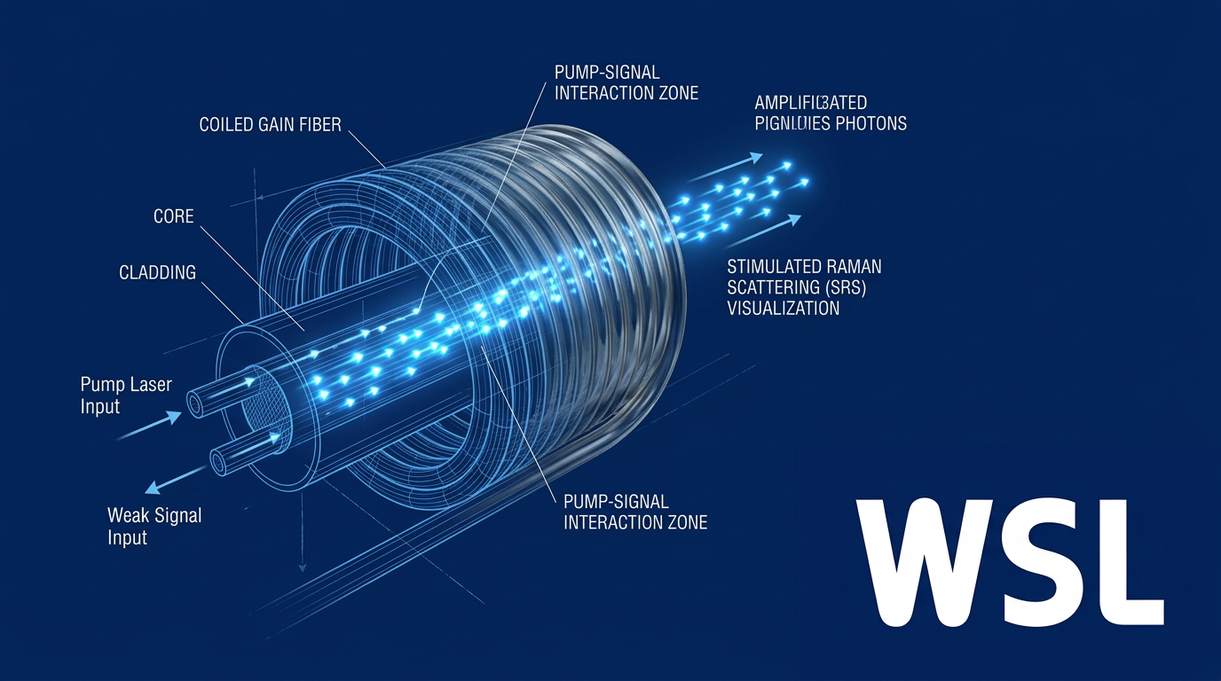
Most optical amplifiers work by doping a fibre with rare-earth ions and exciting those ions with a pump laser — the gain lives in a specially prepared active medium. A Raman fiber amplifier takes a fundamentally different approach: it exploits a nonlinear optical property of silica itself, so the ordinary transmission fibre becomes the gain medium without any dopants at all.
The physical mechanism behind this is stimulated Raman scattering (SRS), a nonlinear interaction between light and the molecular structure of silica glass that transfers energy from a high-power pump wave to a weaker signal wave at a longer wavelength.
Spontaneous and stimulated Raman scattering
Raman scattering occurs when photons interact with the vibrational modes of a material's molecules and emerge at a frequency shifted from the incident light — a phenomenon that, in optical fibres, manifests as one of the most consequential nonlinear effects in the medium.
- Spontaneous Raman scattering: Thermally driven and incoherent. Photons scatter off molecular vibrations and re-emit at a shifted frequency randomly, with no phase relationship and negligible intensity — insufficient for signal amplification.
- Stimulated Raman scattering: Coherent and intensity-driven. Above a pump intensity threshold, signal photons stimulate emission of additional photons at the Stokes-shifted wavelength, producing exponentially growing, amplifier-grade gain.
The distinction is critical for amplifier design: spontaneous Raman scattering is too weak and incoherent to amplify a signal, whereas SRS produces the coherent, cascading gain that makes a practical amplifier possible.
The Stokes shift: energy transfer from pump to signal
During an SRS interaction, a pump photon couples to a silica molecule and excites an optical phonon — a quantised unit of molecular vibration — depositing energy equal to the phonon energy into the lattice.
The pump photon is re-emitted at a lower frequency and correspondingly longer wavelength; this frequency-downshifted photon is the Stokes-shifted photon, and the wavelength difference between pump and emitted photon is the Stokes shift.
At sufficient pump intensity, this process becomes self-reinforcing: the growing population of Stokes photons forms a Stokes wave that stimulates further emission, drawing more energy from the pump in an exponentially growing cascade.
The resulting gain scales with pump intensity and interaction length — longer fibre spans and higher pump powers both increase the amplification available to the signal.
Because SRS is an intrinsic nonlinear property of silica glass, any standard single-mode fibre can act as the gain medium. No rare-earth dopants, no specialised active fibre, and no discrete amplifier element are required — the same fibre that carries the signal also amplifies it.
A direct consequence of the Stokes shift is that the pump wavelength must be shorter than the target signal wavelength, with the offset between them determined by the phonon energy of silica — engineers select the pump wavelength to position gain precisely where the signal wavelength requires it.
For C-band signal amplification, pump wavelengths in the 1400–1500 nm range are typical, reflecting the phonon-energy-driven offset that silica's molecular structure imposes between pump and Stokes wavelengths.
The Raman gain spectrum in silica is notably broad, extending across a wide frequency range from the pump, with peak gain occurring at a well-defined frequency shift set by the dominant phonon modes of silica glass — quantitative figures that the next section examines in detail.
With the physical mechanism and its key parameters established, the next section turns to the shape and behaviour of that gain spectrum, and what it means for bandwidth, wavelength flexibility, and system design.
The Raman Gain Spectrum: Bandwidth, Peak Gain, and Wavelength Flexibility
The Raman gain spectrum is not just a physical property of silica fibre — it is the engineer's primary design variable. Every pump wavelength decision, every multi-pump architecture, and every system that amplifies signals outside the conventional C-band traces back to the specific shape and extent of this curve.
Shape and Bandwidth of the Silica Gain Curve
Unlike the narrow, symmetric Lorentzian profiles associated with atomic transitions, the Raman gain spectrum in silica is broad and distinctly asymmetric — a direct consequence of the amorphous structure of glass and its wide distribution of vibrational modes.
The gain curve exhibits a dominant peak at a specific frequency offset from the pump, with secondary structure at a slightly higher offset; the usable gain extends across a continuum spanning tens of terahertz.
This breadth is not incidental — it is the defining feature that makes Raman amplification inherently broadband-capable in a way that no rare-earth-doped amplifier can match through its gain medium alone.
The Raman Gain Coefficient: What Governs It
The Raman gain coefficient quantifies the efficiency of power transfer from pump photons to signal photons at a given frequency offset — it traces the shape of the gain spectrum curve and reaches its maximum at the dominant gain peak.
Critically, this coefficient is not a fixed material constant: it depends on the fibre effective area, the germanium doping level, and the fibre's nonlinear coefficient (γ).
Smaller effective area concentrates optical intensity for a given pump power, raising gain per unit length. GeO₂ doping increases the Raman gain coefficient relative to pure silica, because germanium-oxygen bonds contribute additional vibrational modes that couple more strongly to the pump field.
The practical engineering intuition follows directly: a fibre with small effective area and elevated germanium content will achieve a given gain target with substantially less pump power than standard single-mode fibre.
- Frequency offset: The gain coefficient follows the gain spectrum curve, peaking at the dominant Stokes-shifted offset and falling off at larger or smaller separations from the pump.
- Effective area (Aeff): Smaller Aeff concentrates pump intensity, raising gain per unit pump power — the key reason specialty fibres outperform standard SMF in discrete amplifiers.
- GeO2 doping level: Higher germanium content increases the Raman gain coefficient relative to pure silica, reducing the pump power required for a given gain target.
- Nonlinear coefficient (γ): γ scales inversely with Aeff and directly with refractive index contrast — fibres with high γ exhibit proportionally higher Raman gain efficiency.
Together, these parameters define the gain efficiency of any given fibre, and understanding their interplay is what separates a well-specified Raman amplifier design from one that simply uses whatever fibre is available.
Pump Wavelength Selects the Gain Window
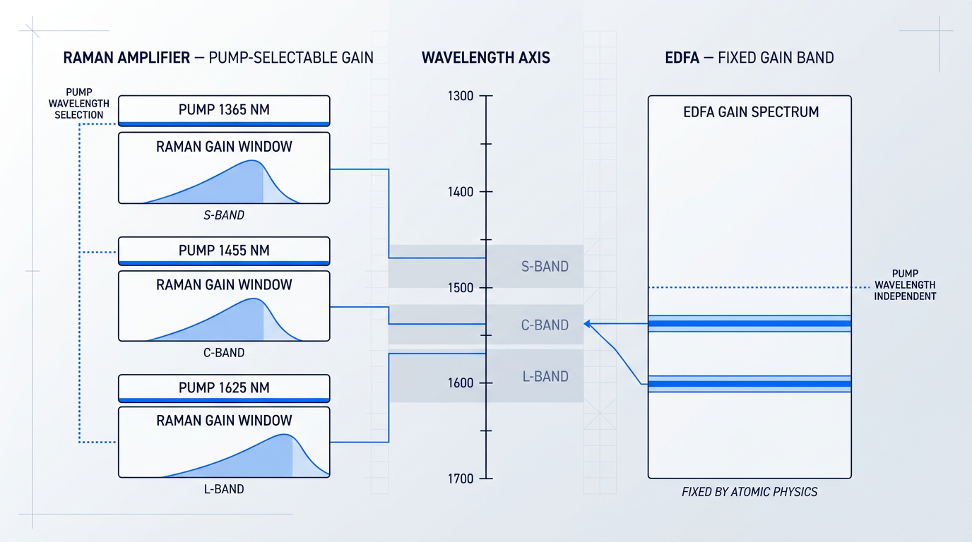
Because Raman gain is centred on the Stokes-shifted frequency below the pump, moving the pump wavelength moves the gain window across the signal band with it — a direct consequence of the fixed frequency offset between pump and peak gain.
For C-band signal amplification, pump wavelengths sitting roughly 100 nm shorter in wavelength are typical; shifting to S-band coverage requires correspondingly shorter pump wavelengths, with the gain window tracking the pump throughout.
This is a genuine architectural degree of freedom: in principle, a Raman amplifier can deliver gain at any wavelength within the fibre's transparency window simply by selecting the appropriate pump, without modifying the gain medium itself.
The contrast with erbium-doped fibre amplifiers is stark at the conceptual level. An EDFA's gain band is fixed by erbium's atomic absorption and emission spectrum to the C- and L-bands — a constraint set by atomic physics, not by system design choices. Raman amplification carries no such constraint: the gain window is determined by the pump, not the dopant.
Multi-Pump Broadband Raman Amplification
A single pump laser produces a gain profile centred on its Stokes-shifted peak, but the gain curve is not flat — it rises, peaks, and then falls, creating ripple across a wide signal band.
The solution is multi-pump Raman amplification: deploying several pump lasers at carefully chosen, distinct wavelengths so that each generates its own Stokes-shifted gain contribution, and the aggregate profile fills in the troughs between individual peaks.
By selecting pump wavelengths whose individual gain curves partially overlap, an engineer can construct a composite gain spectrum that is both broader and flatter than any single pump can produce — enabling amplification across combined C+L bands or even wider multi-band configurations within a single amplifier architecture.
The principle is straightforward: each pump contributes a spectrally shifted copy of the Raman gain curve, and the superposition of those copies produces the broadband flat gain profile that wideband transmission systems require.
Fibre Type and Gain Coefficient Variation
The Raman gain coefficient varies meaningfully across fibre types, and the choice of gain fibre in a discrete amplifier is not a minor detail.
Standard single-mode fibre (SMF), dispersion-shifted fibre (DSF), inverse dispersion fibre (IDF), and highly nonlinear fibre (HNLF) each present different effective areas and nonlinear coefficients — and therefore different gain efficiencies for the same launched pump power.
Fibres with small effective area, such as HNLF and dispersion-compensating fibre (DCF), exhibit significantly higher gain per unit length per unit pump power than standard SMF, making a short coil of specialty fibre a practical and efficient gain medium for discrete Raman amplifier designs.
A Raman fiber amplifier can deliver gain at any wavelength within the fibre's transparency window by selecting the pump wavelength — no change to the gain medium is required. This is the property that makes Raman amplification uniquely suited to multi-band and non-C-band system designs where EDFAs cannot reach.
With the gain spectrum's shape, governing parameters, and wavelength-flexibility principle established, the next question is where in the transmission system that gain is actually applied — and that distinction, between distributed and discrete amplification, shapes every practical deployment decision that follows.
Distributed versus Discrete Raman Amplification
Once you understand how Raman gain works spectrally, the next question is architectural: where does the amplification happen? The answer to that question determines the noise performance, nonlinear impairment accumulation, and deployment model of the entire system — and it splits every Raman amplifier design into one of two fundamentally different configurations.
In distributed Raman amplification (DRA), pump lasers are injected directly into the transmission fibre itself, so that gain is produced continuously and gradually as the signal propagates through the span. The transmission fibre becomes its own gain medium. This is a direct architectural consequence of stimulated Raman scattering occurring in any silica fibre — no discrete active element is required, and no specially prepared waveguide is needed. The same fibre that attenuates the signal will amplify it, provided a pump is present.
Discrete Raman amplification (sometimes called lumped Raman amplification) takes the opposite approach: a dedicated, short fibre coil — typically a highly nonlinear fibre (HNLF) — is housed within a self-contained amplifier unit, and gain is concentrated at that node. Functionally, this is analogous to an EDFA: the amplifier is a distinct component inserted at a specific point in the link. Discrete configurations are used when distributed pump injection into the transmission span is impractical, or when S-band coverage or specialty gain media are required for efficiency.
Why distributed gain improves signal-to-noise ratio
The SNR advantage of distributed gain is best understood as a power-profile argument. In a lumped system, the signal decays continuously over the full span length before being restored at the amplifier node — it spends the majority of its propagation time at low power, accumulating noise throughout.
In a distributed system, gain is applied continuously along the span, partially counterbalancing fibre loss as the signal travels. The signal power never falls as far, and the average signal power across the span is substantially higher. Because noise accumulation scales with the inverse of signal power, the distributed architecture accumulates significantly less noise per span.
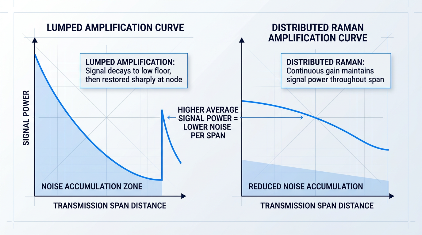
This difference in the shape of the signal power curve along the span is not a marginal effect. Research confirms that distributed Raman amplification results in lower per-channel power variation inside the fibre, leading to measurably higher OSNR compared to a link using discrete EDFA amplifiers alone.
For distributed amplifiers, the standard noise figure definition — the ratio of input SNR to output SNR — cannot be applied in the conventional way, because the gain medium cannot be separated from the transmission span. Instead, engineers use the concept of effective noise figure (ENF), which benchmarks the distributed amplifier's noise performance against a lumped reference with the same total gain.
For sufficiently high distributed on-off gain, the effective noise figure of a distributed Raman amplifier can fall below zero — meaning it outperforms the quantum noise limit of an ideal lumped amplifier with the same total gain. This is not a violation of physics; it arises from the distributed nature of the gain relative to the distributed loss of the span.
The OSNR benefit compounds across both noise and nonlinearity. Because the signal stays stronger throughout the span, less amplified spontaneous emission accumulates per unit length. At the same time, the more uniform power profile reduces nonlinear phase accumulation — lower peak powers mean less Kerr-effect distortion.
Both effects improve optical signal-to-noise ratio at the receiver, and their combination translates directly into greater achievable system reach or higher spectral capacity for a given link budget.
In commercial deployments, the dominant implementation of distributed Raman amplification uses a backward-pumped (counter-propagating) configuration: pump lasers are located at the amplifier node and launched in the direction opposite to signal propagation. This arrangement is preferred because it substantially reduces the transfer of relative intensity noise (RIN) from the pump to the signal — a mechanism covered in detail in the pumping configurations and noise sections that follow.
The maturity of this technology is well established. Distributed Raman amplification was first commercially deployed in 2000–2001 in a cable system for Hydro-Quebec, and it is now systematically used in unrepeatered cable systems spanning more than 350 km. DRA is not a laboratory curiosity; it is a proven architecture for extending reach beyond what lumped amplification alone can achieve.
With the distributed versus discrete distinction established, the next design decision is how pump light is delivered relative to the signal direction — whether co-propagating, counter-propagating, or both simultaneously. That choice is the subject of the following section.
Pumping Configurations: Forward, Backward, and Bidirectional
Once the distributed amplification architecture is chosen, the next decision shapes everything that follows: which direction do you inject the pump light? That single choice determines where gain accumulates along the span, how susceptible the signal is to pump intensity fluctuations, and what noise figure the system can realistically achieve — and each answer pulls in a different direction.
In forward (co-propagating) pumping, pump and signal light travel in the same direction through the fibre, so gain is concentrated near the fibre input where pump power is highest before propagation losses deplete it.
This front-loading of gain keeps signal power high early in the span, which limits the accumulated amplified spontaneous emission (ASE) the signal encounters before reaching the receiver — producing the lowest ASE-defined noise figure of the three configurations.
The liability is severe, however: because pump and signal are co-propagating, pump intensity fluctuations couple directly and persistently into signal intensity noise across the full interaction length.
Raman gain responds instantaneously to pump power changes — unlike EDFA gain, which responds on millisecond timescales — so there is no temporal averaging available to suppress this RIN transfer; every pump fluctuation imprints directly on the signal.
In backward (counter-propagating) pumping, the pump travels in the opposite direction to the signal, so the pump enters the fibre at the output end and is at its highest power where the signal is about to exit — concentrating gain near the fibre output.
The RIN picture reverses entirely: because pump and signal travel in opposite directions, pump fluctuations at any given point are averaged over the full fibre transit time before they can couple into the signal, substantially suppressing RIN transfer compared to the forward geometry.
This RIN advantage is why backward pumping is the most commonly deployed configuration in commercial distributed Raman systems — the noise figure penalty relative to forward pumping is accepted because the RIN performance is far more tractable in real-world deployments.
Bidirectional pumping injects pump lasers from both ends simultaneously, distributing gain more evenly along the span rather than concentrating it at either end.
By combining forward and backward pump contributions, the effective noise figure sits between the two single-direction configurations — improving on backward-only NF while not fully incurring the RIN penalty of forward-only pumping.
The cost is system complexity: bidirectional pumping requires two sets of pump lasers, two launch points, and precise power balancing between them, making it the engineering compromise that extracts the best of both configurations at the price of deployment overhead.
The table below quantifies the NF contrast across all three configurations using published numerical modelling results, alongside their gain profile characteristics and RIN susceptibility.
| Configuration | Gain Profile | Min. NF (100 km span) | RIN Susceptibility | Typical Deployment |
|---|---|---|---|---|
| Forward (co-propagating) | Front-loaded: high gain near fibre input | ~11 dB (co-pumping minimum) | High — instantaneous pump-to-signal coupling across full span | Unrepeatered links where OSNR gain outweighs RIN risk; low-noise pump sources required |
| Backward (counter-propagating) | Back-loaded: high gain near fibre output | ~8.6 dB (counter-pumping minimum) | Low — pump fluctuations averaged over fibre transit time | Standard commercial distributed Raman; most long-haul DWDM deployments |
| Bidirectional | Distributed: gain spread across full span | ~9.7 dB (bidirectional minimum) | Moderate — forward component introduces partial RIN coupling | Systems requiring improved NF over backward-only with manageable complexity |
Comparison of the three primary Raman pumping configurations across gain profile, noise figure, RIN susceptibility, and typical deployment context, using published NF figures from numerical modelling studies.
The NF figures — approximately 8.6 dB for counter-pumping, 9.7 dB for bidirectional, and 11 dB for co-pumping at 100 km — come from published modelling of distributed Raman amplifiers across all three pump schemes, and they reveal the core engineering tension clearly.
Forward pumping's lower NF is not a free advantage: it arrives paired with the highest RIN susceptibility, and commercially available Raman pump lasers carry significant inherent RIN that limits the practically usable forward pump power in real systems.
Forward pumping achieves the lowest ASE-defined noise figure but the worst RIN transfer. Backward pumping delivers the best RIN performance at a higher NF. No configuration wins on both axes simultaneously — the designer's job is to choose which penalty is more tolerable for their system.
Bidirectional pumping's intermediate NF (approximately 9.7 dB) represents a meaningful improvement over backward-only operation, but the forward pump component still introduces partial RIN coupling — and studies of bidirectional systems have documented significant Q-factor penalties when forward pump power ratios are not carefully controlled.
Higher-Order Pumping: Second- and Third-Order Cascades
Higher-order pumping extends the basic configurations by using cascaded Raman conversion rather than pumping the signal band directly: a primary pump drives gain in a secondary pump wavelength, which in turn drives gain in the signal band.
This cascade pushes the effective gain region further into the fibre span, reducing signal power excursions over longer distances and improving OSNR by spreading amplification more deeply into the transmission medium.
Published investigations of higher-order configurations for WDM systems show that at 36 dB on-off gain, second-order forward pumping achieves an equivalent noise figure (ENF) improvement of approximately 1 dB, and third-order pumping approximately 2 dB, relative to first-order configurations.
The practical constraint is efficiency: pump power requirements grow with each cascaded order, and the Raman fiber lasers typically used as high-power sources for third-order pumping carry significantly higher RIN than laser diodes — introducing additional RIN transfer that can partially or fully offset the OSNR benefit.
Third-order codirectional pumping in particular has been shown to introduce random phase variations via the Kerr effect that impair phase-modulated signals, meaning the achievable performance improvement in advanced modulation formats is typically smaller than theoretical gain-profile calculations predict.
Raman gain is inherently polarisation-selective: the gain coefficient reaches its maximum when pump and signal are co-polarised, and is minimised when they are orthogonally polarised, so fluctuating birefringence along a real fibre span produces polarisation-dependent gain (PDG) — a source of signal impairment that varies stochastically with the fibre's birefringence state.
Standard commercial practice addresses this through polarisation multiplexing of pump lasers — combining two orthogonally polarised pump beams via a polarisation beam combiner — or through use of a Lyot depolariser, both of which present an effectively unpolarised pump to the fibre and suppress PDG.
Backward pumping substantially reduces PDG compared to forward pumping: in the counter-propagating geometry, the rapid relative polarisation evolution between pump and signal — driven by the large effective frequency sum of the two counter-travelling waves — causes fast polarisation decorrelation that averages out the gain anisotropy, though PDG in a counter-pumped amplifier is not negligible and remains roughly three times smaller than in a co-pumped system rather than zero.
The RIN transfer mechanisms and PDG physics introduced here underpin the full noise analysis that follows in the next section, where ASE, double Rayleigh backscattering, RIN transfer quantification, and PDG mitigation strategies are each examined in rigorous detail.
Noise Mechanisms in Raman Fiber Amplifiers
A Raman fiber amplifier's performance ceiling is not set by its gain — it is set by how well its noise mechanisms are understood and managed. The four principal noise sources (amplified spontaneous emission, double Rayleigh backscattering, RIN transfer, and polarisation-dependent gain) are not independent liabilities to be minimised in isolation; they interact, they trade off against each other, and the pumping configuration choices made in system design determine which ones dominate. Mastering this interaction is where Raman system engineering expertise actually lives.
Amplified Spontaneous Emission and Noise Figure
Amplified spontaneous emission (ASE) in a Raman fiber amplifier originates from the same phonon-driven scattering process that produces signal gain: spontaneous Raman scattering continuously generates photons across the gain bandwidth, and those photons are then amplified by the same pump field that amplifies the signal.
This distinguishes Raman ASE fundamentally from its counterpart in EDFAs, where spontaneous emission arises from population inversion in a rare-earth dopant. In a Raman system there is no metastable population — ASE is an ever-present consequence of the scattering process itself, present at any pump power level.
When double Rayleigh backscattering and RIN transfer are well controlled, ASE becomes the dominant noise floor, and the standard figure of merit for characterising it is the noise figure (NF): the ratio of input signal-to-noise ratio to output SNR, expressed in decibels.
Measuring NF in a distributed Raman amplifier presents a practical challenge: the transmission fibre cannot be physically separated from the amplifying medium, so the conventional input/output NF measurement does not apply directly. The standard approach is the on/off gain metric — measuring optical signal-to-noise ratio with the Raman pump active and then with it switched off, comparing the two OSNR values to infer the effective amplifier noise performance.
The counterintuitive result of this measurement is that the effective noise figure of a distributed Raman amplifier can be negative in decibel terms — a physical impossibility for a lumped amplifier but entirely valid here, because the gain is distributed along the span rather than applied at its end. By amplifying the signal continuously as it propagates (and thus preventing the signal from decaying to its lowest power before amplification), the distributed architecture reduces the integrated noise accumulation relative to a lumped system with equivalent total gain.
Pump power level shapes ASE behaviour in a non-trivial way: increasing pump power raises gain and suppresses signal-ASE beat noise up to a point, but excessive pump power drives the system into a regime where stimulated Raman scattering between ASE photons themselves becomes significant, degrading OSNR through saturation-induced ASE amplification.
Double Rayleigh Backscattering
Double Rayleigh backscattering (DRB) is a consequence of a fundamental property of silica fibre: Rayleigh scattering redirects a small fraction of signal light in the backward direction at every point along the span. In a passive fibre this is a minor loss mechanism, but in a Raman-pumped span the backward-propagating scattered light is re-amplified by the pump as it travels back toward the source.
A second Rayleigh backscattering event then redirects a fraction of this amplified backward light forward again, so that it co-propagates with the original signal at the same wavelength and within the same optical bandwidth. This double-backscattered light constitutes multipath interference (MPI) noise — a coherent noise floor that cannot be removed by optical filtering because it is spectrally indistinguishable from the signal itself.
DRB noise power scales with both fibre length and Raman gain: longer spans and higher on-off Raman gains produce disproportionately larger MPI contributions, because each additional unit of gain amplifies both the signal and the backscattered components that will eventually re-interfere with it.
This scaling relationship sets a practical upper bound on achievable distributed gain within a single span. In ultra-long-haul and unrepeatered systems — precisely the configurations where high distributed gain is most desirable — DRB becomes the binding constraint on how aggressively the Raman pump can be driven, and careful gain management is required to keep MPI below the system penalty threshold.
RIN Transfer from Pump to Signal
Raman gain responds to changes in pump power on a timescale set by the phonon dephasing time in silica — effectively instantaneous at the signal frequencies of interest. Unlike EDFA gain, which is buffered by the erbium metastable lifetime (on the order of milliseconds), Raman gain tracks pump intensity fluctuations directly, coupling the pump laser's relative intensity noise (RIN) into signal amplitude noise.
The degree of RIN transfer depends critically on the pumping configuration established in the previous section. In forward (co-propagating) pumping, pump and signal travel together over the full fibre length, so pump intensity fluctuations accumulate coherently along the propagation path and couple strongly into signal noise. In backward (counter-propagating) pumping, pump and signal travel in opposite directions; fluctuations in the pump are averaged over the transit time of the fibre, which substantially attenuates the RIN transfer to the signal.
This RIN averaging in backward pumping is one of the primary reasons counter-propagating configurations dominate commercial deployments, even though backward pumping carries a higher ASE-defined noise figure than forward pumping (as established in the pumping configurations section, with counter-pumping NF around 8.6 dB versus co-pumping values that can reach 15.49 dB at 100 km spans — the NF penalty of forward pumping is offset by its RIN advantage only when pump laser quality is very high).
Mitigation for RIN transfer operates on three levers: pump laser selection (low-RIN sources, such as Fabry-Perot cavity designs in certain operating regimes, reduce the noise available for transfer); configuration choice (backward pumping as the default for RIN-sensitive systems); and, in bidirectional configurations, careful allocation of forward and backward pump power fractions to limit the RIN contribution of the co-propagating component.
Polarisation-Dependent Gain
The Raman gain coefficient in silica fibre is polarisation-selective: energy transfer from pump to signal is most efficient when the two fields share a specific polarisation relationship, and least efficient when they are orthogonally polarised. In standard single-mode fibre, where birefringence fluctuates randomly along the span, the signal encounters a gain that varies with its instantaneous polarisation state relative to the pump — a phenomenon known as polarisation-dependent gain (PDG).
PDG manifests as signal amplitude fluctuations that track polarisation state evolution, degrading OSNR in a way that is difficult to characterise or compensate at the receiver. Its severity is strongly configuration-dependent. Backward pumping substantially reduces PDG relative to forward pumping: because pump and signal propagate in opposite directions, the effective sum of their optical frequencies is very high, which drives rapid polarisation decorrelation between the two fields and averages out the polarisation-selective gain along the span. Forward pumping does not benefit from this averaging mechanism.
The standard commercial mitigation is polarisation multiplexing of the pump: two pump beams of equal power and orthogonal polarisation states are combined via a polarisation beam combiner before launch, presenting an effectively unpolarised field to the signal and averaging the polarisation-selective gain to a near-constant value. Lyot depolarisers serve the same purpose by scrambling the pump polarisation state, and are used in configurations where beam combining is impractical.
The Central Design Tension: Balancing Noise Mechanisms
These four noise mechanisms do not occur in isolation, and the conditions that improve one metric routinely degrade another. High distributed gain improves the effective NF advantage of the distributed architecture but simultaneously increases DRB noise power, since both scale with the same on-off gain figure. Forward pumping produces the lowest ASE-defined NF but couples pump RIN most strongly to signal noise and offers no PDG averaging benefit. Backward pumping controls RIN transfer and reduces PDG but carries a higher ASE noise figure.
Forward pumping minimises ASE-defined noise figure but maximises RIN transfer and PDG. Backward pumping minimises RIN transfer and PDG but raises the ASE noise figure. No single configuration eliminates all four noise mechanisms simultaneously — bidirectional pumping exists precisely as the engineering compromise between these competing constraints, and the forward-to-backward power ratio is the primary tuning variable.
Bidirectional pumping is the practical resolution to this tension: by distributing gain between co- and counter-propagating pumps, it improves effective NF relative to backward-only configurations while keeping RIN transfer manageable by limiting the fraction of total pump power in the forward direction.
Higher-order pumping addresses the DRB constraint from a different angle: by pushing the effective gain region deeper into the span via cascaded Stokes shifts, it improves the effective NF (by approximately 1 dB at second order and 2 dB at third order for a 36 dB on-off gain target) while keeping the on-off gain at any single Stokes order modest, which limits the DRB accumulation at each stage.
Across all configurations, pump power management is non-negotiable: over-pumping drives saturation-induced ASE degradation that erases the NF benefit of distributed gain, and multi-pump systems require careful power allocation to avoid preferentially amplifying ASE at the expense of signal OSNR.
The noise characteristics examined here — particularly the effective NF advantage that distributed Raman configurations achieve over lumped amplification — are central to understanding when a Raman fiber amplifier is the preferred architecture over an EDFA, which the next section examines directly.
Raman Fiber Amplifiers vs. EDFAs: A System Design Analysis
Every engineer evaluating amplifier technology for a new optical link eventually arrives at the same question: Raman or EDFA? The honest answer is that neither technology is generically superior — the right choice is always a function of span length, spectral band, noise budget, and operational constraints.
The most fundamental distinction is architectural. EDFAs derive gain from erbium ions embedded in a short doped fibre segment, and those ions only absorb pump light and emit signal photons within a fixed spectral window: the C-band (1530–1565 nm) and, with adjusted inversion levels, the L-band (1565–1625 nm).
A Raman fiber amplifier, by contrast, uses the transmission fibre itself as the gain medium, exploiting stimulated Raman scattering to shift pump photon energy to the signal. Because the Stokes shift is a fixed ~13 THz offset from the pump frequency, gain can be positioned at any signal wavelength simply by selecting the appropriate pump wavelength — including the S-band (1460–1530 nm), which lies entirely outside the erbium emission band.
This wavelength agnosticism is not merely a feature; it is an architectural freedom that EDFAs structurally cannot match, and it is the primary reason Raman amplification is the only near-term candidate for ultra-wideband (UWB) amplification beyond the C+L band window.
The second major axis is gain distribution, which directly determines noise performance. As covered in the distributed vs. discrete architecture discussion earlier, EDFAs are inherently lumped: gain is concentrated at discrete nodes, and signal power follows a sawtooth profile along the link, falling steeply across each span before being restored at the next amplifier site.
Distributed Raman amplification smooths this profile by providing gain continuously along the transmission fibre, partially compensating loss before ASE can accumulate — which is precisely why the effective noise figure of a distributed Raman amplifier can fall well below the 4–6 dB range achievable by even the best EDFAs.
The mathematics of cascaded amplifier noise make this concrete: for a lumped amplifier with 20 dB of gain and a 3.3 dB intrinsic noise figure, the power penalty from lumped versus distributed amplification is approximately 13.3 dB — meaning an equivalent distributed amplifier achieving the same total gain carries an effective noise figure of roughly −10 dB.
This effective NF advantage belongs specifically to distributed Raman configurations; a lumped or discrete Raman amplifier, where gain is confined to a dedicated fibre spool rather than spread across the transmission span, does not carry it.
| Parameter | EDFA | Distributed Raman Amplifier |
|---|---|---|
| Gain wavelength range | C-band: 1530–1565 nm; L-band: 1565–1625 nm (erbium-constrained) | Any wavelength; set by pump selection (e.g. S-band, C-band, L-band) |
| Noise figure | 4–6 dB (high-quality amplifiers) | Effective NF well below 0 dB possible; −10 dB in worked cascade example |
| Pump wavelength | 980 nm or 1480 nm | ~100 nm shorter than signal wavelength (e.g. ~1450 nm for C-band signal) |
| Pump power per stage | 100 mW to ~2 W (single-emitter diode laser) | ~1 W or greater launched into transmission fibre |
| Gain type | Lumped (discrete amplifier node) | Distributed along transmission span |
| Amplification bandwidth | ~40 nm (~5 THz, C-band) | ~100 nm (~12.5 THz, multi-pump configurations) |
| Modelled max. AIR (2000 km SSMF) | ~75 Tbit/s (DP-1024QAM, FF-NLC + PS) | ~223 Tbit/s (DP-1024QAM, FF-NLC + PS) |
| Gain response time | Millisecond timescale (erbium metastable state) | Femtosecond timescale (instantaneous to pump changes) |
| Primary deployment context | Terrestrial and submarine repeatered networks | Unrepeatered spans >350 km; S-band; UWB systems |
Side-by-side quantitative comparison of Raman fiber amplifiers and EDFAs across the key system design axes engineers use to select between them.
The table's most striking figure is the information rate gap: modelling of probabilistically shaped DP-1024QAM transmission over 2000 km of standard single-mode fibre, with feed-forward nonlinearity compensation, yields approximately 75 Tbit/s for EDFA amplification versus approximately 223 Tbit/s for distributed Raman amplification — a factor of roughly three, driven almost entirely by the ~100 nm Raman bandwidth against the ~40 nm EDFA window.
That capacity advantage is real, but it is conditional: it materialises only when the system is designed around wideband multi-pump Raman configurations, with the engineering complexity and pump power overhead that entails.
The gain response time difference is one of the most practically consequential distinctions for system engineers. Erbium's metastable upper-state lifetime means EDFA gain responds on millisecond timescales, making it effectively immune to fast pump fluctuations and simplifying automatic gain control design considerably.
Raman gain, by contrast, responds on femtosecond timescales — essentially instantaneously to pump power changes — which is why relative intensity noise (RIN) transfer from pump to signal is a first-order design concern in Raman systems, as examined in the noise mechanisms section.
In practice, backward (counter-propagating) pumping is the standard commercial configuration precisely because pump fluctuations are averaged over the full fibre propagation time before they can imprint on the signal, substantially reducing RIN transfer — but it does not eliminate the design requirement to use low-RIN pump sources.
The pump power requirement deserves equally honest treatment. EDFA pump diodes at 980 nm or 1480 nm typically deliver 100 mW to approximately 2 W per emitter into a short doped fibre segment. Raman amplifiers require pump powers of roughly 1 W or greater launched directly into the transmission fibre, which introduces practical field constraints that EDFAs simply do not face.
High pump power in the transmission fibre raises eye-safety concerns, demands exceptionally clean connectors (contaminated connectors can cause catastrophic damage or fire at these power levels), and adds measurable power consumption and cost overhead — factors that have historically limited Raman uptake in standard SSMF terrestrial networks despite its theoretical performance advantages.
These are genuine engineering constraints, not disqualifying weaknesses: the same power that creates operational complexity also enables the distributed gain profile that produces the noise figure advantage, and for unrepeatered undersea systems spanning more than 350 km — where span loss can reach 60 dB and there is no opportunity to place amplifiers mid-span — that trade-off is clearly favourable.
Distributed Raman amplification's noise figure and bandwidth advantages are real, but they are conditional on span length, spectral band, and the operational willingness to manage high pump power. EDFAs dominate repeatered terrestrial and submarine networks because their simplicity and maturity are genuinely superior in that context — not because Raman is immature.
For system engineers, the practical decision matrix looks like this: choose EDFA where span lengths are standard (typically 80 km), operational simplicity is valued, and C+L band coverage is sufficient; reach for distributed Raman where spans are ultra-long, S-band coverage is required, or the noise figure improvement justifies the pump power overhead and operational discipline it demands.
Understanding where each technology excels in isolation is the prerequisite for the more sophisticated question: when does combining them make sense? Hybrid Raman-EDFA architectures exist precisely to capture the noise figure advantage of distributed Raman while retaining the gain efficiency and operational maturity of EDFA — and that is the subject of the next section.
Need an EDFA Tailored to Your System?
When your application calls for an EDFA, the right configuration matters. Woodrow Scientific offers tailored EDFAs built around your specific wavelength, power, and application requirements.

Hybrid Raman-EDFA Amplifier Configurations
The question that follows naturally from understanding both technologies in isolation is whether their limitations are complementary — and they are. Hybrid Raman-EDFA (HRE) architectures are not a compromise between two imperfect solutions; they are a deliberate noise engineering decision that produces system performance neither technology can reach alone.
The structural logic is precise: distributed Raman pre-amplification occurs within the transmission span itself, with counter-propagating pump light launched from the amplifier node back into the fibre. By the time the signal arrives at the EDFA stage, it has already been partially amplified with very low added noise — which means the EDFA's own noise contribution is applied to a stronger signal, reducing the effective noise figure of the combined amplifier below anything a lumped EDFA alone could achieve.
In demonstrated HRE systems, the distributed Raman stage reduced the effective NF to an average of 1.4 dB — enabling fibre spans of 70 km and delivering 3 dB of additional span loss tolerance compared to conventional C+L EDFA-only configurations. That 3 dB translates directly into longer reaches and wider loss budgets, opening transmission links that would otherwise require additional amplifier sites.
The practical question for system designers is what this NF improvement translates to in actual network capacity. The throughput figures from optimised hybrid versus lumped configurations in the same link make the answer concrete.
| Configuration | Throughput (Tbit/s) | Total Launch Power (dBm) |
|---|---|---|
| Optimised hybrid Raman-EDFA | 99.22 | 20.4 |
| Optimised lumped (EDFA-only) | 88.55 | 23.0 |
Direct comparison of optimised hybrid Raman-EDFA versus optimised lumped EDFA-only configurations on throughput and total launch power, demonstrating the counter-intuitive relationship between capacity gain and power reduction.
The table reveals a result that runs counter to the usual assumption that higher capacity requires more power. The hybrid configuration achieved 12% greater throughput while operating at 2.6 dBm lower total launch power — because the improved OSNR from distributed Raman gain means less signal power is needed to overcome noise, which in turn reduces nonlinear interference accumulation across the link. Better capacity and lower nonlinear penalty are achieved simultaneously, not traded off against each other.
Optimised hybrid Raman-EDFA amplification achieved 99.22 Tbit/s at 20.4 dBm total launch power versus 88.55 Tbit/s at 23 dBm for EDFA-only — a 12% capacity gain that simultaneously reduces nonlinear interference, not a trade-off between the two.
Beyond noise figure and throughput, HRE architectures open a spectral engineering dimension that single-technology systems cannot match. Multiple Raman pump wavelengths can be combined with the EDFA gain band to produce a seamless gain profile across a range wider than C+L combined.
- Continuous gain bandwidth: 1525–1616 nm (91 nm), achieved by combining distributed Raman gain with a single EDFA stage.
- Dual pump wavelengths: Counter-propagating pumps at 1427 nm (300 mW) and 1495 nm (310 mW) fill spectral gaps a single pump cannot cover.
- Gain flattening filter: A 91 nm gain flattening filter (GFF) equalises the combined gain profile across the full amplifier bandwidth.
- Record capacity demonstrated: 120 Tbit/s transmitted over 9 × 70 km spans using this HRE architecture — a single-mode fibre capacity record.
Two counter-propagating pump wavelengths achieve what a single pump cannot: each pump generates a Raman gain peak shifted approximately 13.2 THz from its wavelength, and by selecting 1427 nm and 1495 nm, the two gain peaks are positioned to cover complementary spectral regions that together span the full 91 nm band. The gain flattening filter is essential here — without it, the combined Raman and EDFA gain profile would be spectrally uneven, and the resulting channel power variation would degrade transmission performance across the band.
The 120 Tbit/s result over 9 × 70 km is the synthesis of every preceding element in this section: the long spans are enabled by the 1.4 dB effective NF, the wide continuous gain bandwidth is enabled by the dual-pump Raman architecture, and the high aggregate throughput follows from both. This is not a laboratory curiosity — it is a demonstration that HRE architectures are production-relevant at record-setting capacity levels.
A further practical benefit arises when dispersion-compensating fibre (DCF) is used as the Raman gain medium. DCF is normally a passive loss element that degrades system margin; when pumped for Raman amplification, it instead delivers net gain, converting a budget liability into an asset. This wider system margin creates room to insert elements such as optical add-drop multiplexers that would otherwise be excluded by loss budget constraints.
Design Optimisation in Hybrid Raman-EDFA Systems
HRE design is a genuine optimisation problem. The gain split between the Raman and EDFA stages, pump wavelength selection, and pump power allocation all interact — and the configuration that maximises throughput for a 70 km SMF span will not be optimal for a different span length, spectral band, or nonlinear penalty budget. There is no universal setting; each transmission system requires its own evaluation.
Understanding when to hybridise, and how to balance the gain split, is what separates competent amplifier selection from expert system design. The architectural choices covered here play out across a wide range of real deployment contexts — which the next section examines in detail.
Applications of Raman Fiber Amplifiers
The engineering principles covered throughout this guide — distributed gain, wavelength flexibility, the distinction between spontaneous and stimulated Raman scattering — are not academic abstractions. They map directly onto deployed systems across telecommunications, industrial sensing, clinical diagnostics, and scientific instrumentation. Understanding where a Raman fiber amplifier actually operates reveals how much of its value lies outside the telecom rack.
Long-Haul Telecommunications
Telecommunications remains the dominant deployment context for Raman amplification, and for good reason: distributed Raman gain directly addresses the noise and span-loss constraints that limit how far a signal can travel without electronic regeneration.
Unrepeatered transmission systems represent the clearest expression of this capability. IEEE-published demonstrations have achieved unrepeatered 100G transmission over distances exceeding 500 km on standard G.652 fiber, with one demonstration reaching 627 km — figures that would be unachievable without Raman amplification supplementing or replacing conventional inline repeaters.
In ultra-long-haul and submarine cable systems, Raman amplification works alongside EDFA in the hybrid architectures covered in the previous section — its role there is to reduce the effective noise figure at the start of each span, extending the reach and capacity of systems where every decibel of noise margin matters.
The wavelength flexibility of Raman gain — established in the gain spectrum section — also shapes WDM system design: Raman pumping enables amplification in the S-band and at wavelengths beyond the C+L window that EDFAs cannot efficiently serve, making it the practical enabler of bandwidth expansion in high-capacity terrestrial networks.
Distributed Temperature Sensing
Raman optical time-domain reflectometry (ROTDR) is the sensing application of spontaneous Raman scattering — the same physical process introduced in the opening section of this guide, but exploited here for measurement rather than amplification.
A laser pulse is launched into a sensing fiber, and the backscattered spontaneous Raman signal is analyzed at the receiver. The ratio of anti-Stokes to Stokes intensities is temperature-dependent: the anti-Stokes component carries stronger temperature sensitivity and serves as the primary measurement channel, while the Stokes signal provides the normalization reference.
The result is a continuous, spatially resolved temperature profile along the entire fiber length — not a set of discrete point measurements, but a distributed measurement that mirrors the distributed gain concept from the architecture section, applied here to sensing.
Raman-based distributed temperature sensing (RDTS) is widely deployed in oil and gas wells for downhole monitoring, in transportation tunnels for fire detection, along pipelines for leak localization, and on high-voltage power cables for thermal overload warning — applications where a single fiber replaces thousands of discrete point sensors.
Raman DTS responds exclusively to temperature. Brillouin scattering, by contrast, is sensitive to both strain and temperature simultaneously — requiring additional compensation to isolate either parameter. In applications such as power cable monitoring or pipeline surveillance where mechanical strain is present but only thermal data is needed, Raman DTS delivers clean temperature measurements without strain cross-sensitivity, eliminating a calibration burden that Brillouin-based systems must manage.
For applications requiring simultaneous temperature and strain measurement, hybrid sensing architectures combine Raman DTS with Brillouin or Rayleigh sensing on the same or parallel fibers — a configuration that places Raman within a broader distributed fiber sensing ecosystem rather than treating it as a standalone solution.
Biomedical Imaging and Spectroscopy
Raman amplification's SNR advantage — the same principle that drives its use in low-noise telecom spans — also makes it valuable in biomedical signal recovery, where weak optical signals returned from tissue must be amplified without degrading the diagnostic information they carry.
In optical coherence tomography (OCT) and ultrafast laser-based imaging, distributed Raman amplification has been integrated to boost detection sensitivity. Published analytical models confirm that optically post-amplified systems using Raman amplifiers can achieve a sensitivity improvement of up to 20 dB in the visible to near-infrared spectral range without sacrificing imaging speed — a figure reported in peer-reviewed biomedical sensing literature.
A related body of clinical research has established fiber-optic Raman spectroscopy as a label-free, non-invasive diagnostic technique for tissue characterization, with fibre-optic probes enabling in vivo measurements during endoscopic procedures.
- In vivo cancer screening: Fiber-optic Raman probes acquire molecular fingerprint spectra from tissue in real time during endoscopy, enabling differentiation of normal, precancerous, and malignant tissue.
- Surgical margin demarcation: Needle-based and handheld Raman probes assess resection margins intraoperatively, helping surgeons confirm complete tumor removal with objective spectral classification.
- Hollow organ endoscopy: Raman endoscopy has been validated in the stomach, esophagus, nasopharynx, larynx, and colon — organs accessible via standard clinical endoscopes.
- Needle-based solid tissue assessment: Thin fiber-optic needle probes inserted into solid tissue measure Raman spectra for rapid, minimally invasive diagnosis without excisional biopsy.
The clinical attractiveness of fiber-optic Raman spectroscopy rests on its label-free nature: tissue is characterized by its intrinsic molecular vibrations, with no contrast agent or ionizing radiation required. Published clinical studies report diagnostic accuracies above 90% for several cancer types using fiber-optic Raman probes at endoscopy.
Scientific Instrumentation
The wavelength flexibility argument from the gain spectrum section reaches its most specialized expression in scientific instrumentation: Raman fiber amplifiers provide gain at wavelengths that rare-earth-doped fiber amplifiers simply cannot access, making them the enabling technology for a range of photonic sources.
Applications include tunable sources for spectroscopy, photoacoustic imaging systems operating in the near-infrared, and power scaling of optical sources used in precision measurement.
Cascaded Raman processes extend operation progressively to longer wavelengths through successive Stokes shifts, with published demonstrations reaching signal generation across the 2–5 μm mid-infrared range using silicon core and hollow-core fiber platforms — a spectral region rich in molecular absorption features relevant to gas sensing and environmental monitoring.
This mid-infrared reach, achieved through cascaded Raman amplification rather than rare-earth gain media, is precisely the kind of capability that positions Raman fiber technology as a platform for applications the telecom-centric view of this field does not capture.
With the application landscape mapped across telecommunications, distributed sensing, biomedical diagnostics, and scientific instrumentation, the final section draws together the guide's arc — from the physics of stimulated Raman scattering through to the system architectures and real-world deployments that depend on it.
Conclusion
Conclusion
What makes a Raman fiber amplifier genuinely different is not a feature list — it is the physics: gain arises from the transmission fibre itself, a consequence of stimulated Raman scattering in silica, not from a doped active medium inserted into the path.
That distinction shapes every engineering decision that follows — the distributed architecture, the wavelength flexibility, the noise trade-offs, and the cases where a hybrid approach outperforms either technology alone.
For system designers, span length, spectral band, and noise figure are the axes worth returning to; for those in sensing or biomedical work, the literature on ROTDR and fibre-optic Raman probes is the natural next step.
Frequently asked questions about Raman fibre amplifiers
Common questions about Raman fibre amplifier physics, configurations, noise mechanisms, and applications — answered concisely.
A fibre amplifier boosts an optical signal directly within the optical fibre itself, without converting the light to an electrical signal and back. This all-optical amplification compensates for the attenuation that accumulates as light travels over long distances through glass, which would otherwise degrade the signal below usable levels. By restoring signal power in the optical domain, fibre amplifiers enable long-haul and ultra-long-haul wavelength-division multiplexed (WDM) transmission without costly optoelectronic regeneration — the detect, decode, and re-transmit process — at every node along the route. Raman amplifiers are one type of fibre amplifier; erbium-doped fibre amplifiers (EDFAs) are another.
Raman amplifiers use stimulated Raman scattering in standard silica fibre — they are wavelength-flexible and can provide gain distributed along the transmission span itself. EDFAs use erbium-doped fibre and deliver fixed C/L-band gain at discrete amplifier nodes; they are simpler to deploy and require significantly lower pump power. Three decision axes separate the technologies in practice. First, wavelength range: Raman gain is determined by the pump wavelength, making it band-agnostic; EDFA gain is fixed by the erbium absorption spectrum. Second, noise figure: distributed Raman can achieve an effective noise figure below that of even the best EDFAs, whereas lumped Raman cannot. Third, pump power: Raman systems require substantially higher pump power, with real implications for eye safety, connector cleanliness, and power consumption. Neither technology is generically superior — the right choice depends on span length, spectral band, and noise figure requirements.
The two types are spontaneous Raman scattering and stimulated Raman scattering (SRS). Spontaneous Raman scattering is incoherent and thermally driven — it occurs at all light intensities, with scattered photons emitted in random directions at a frequency shift set by molecular vibration. The signal is inherently weak. This is the physical basis of Raman spectroscopy and distributed temperature sensing, where the ratio of anti-Stokes to Stokes backscatter intensities encodes temperature along the fibre. Stimulated Raman scattering is coherent and intensity-threshold-driven. When pump intensity is sufficient, the Stokes wave grows exponentially as pump photons continuously transfer energy to signal photons at the Stokes-shifted wavelength. This is the mechanism behind Raman fibre amplifiers and Raman fibre lasers. The practical distinction: spontaneous Raman is the sensing phenomenon; stimulated Raman is the amplification phenomenon.
The pump wavelength is chosen to be approximately 100 nm shorter than the target signal wavelength, corresponding to the roughly 13 THz Stokes frequency shift that produces peak Raman gain in silica fibre. For C-band signal amplification around 1550 nm, pump wavelengths in the region of 1450 nm are typical. Because the gain band is set by the pump wavelength rather than a dopant absorption spectrum, Raman amplification can in principle be delivered at any wavelength within the fibre's transparency window simply by selecting the appropriate pump. Multiple pump wavelengths can also be combined to broaden and flatten the gain spectrum, enabling wideband amplification across C+L or S+C+L bands — an architectural flexibility that EDFAs cannot match.
Double Rayleigh backscattering (DRB) is a multipath interference (MPI) noise mechanism in which signal light undergoes two successive Rayleigh backscattering events. The first scattering event sends light backwards through the fibre, where it is re-amplified by the Raman pump. The second event scatters it forward again, so it co-propagates with the original signal as a noise component. This re-amplified backscattered light arrives at the receiver with a random phase and delay relative to the original signal, creating interference noise that degrades the optical signal-to-noise ratio (OSNR). DRB noise power grows with both fibre length and Raman gain — longer spans and higher gain levels make the problem progressively worse. DRB is particularly significant in high-gain distributed Raman configurations and places a practical upper limit on achievable gain in distributed systems, requiring careful gain management and span length optimisation.
Yes — and the range of non-telecom applications is substantial. In distributed temperature sensing (ROTDR), Raman optical time-domain reflectometry exploits the temperature dependence of spontaneous Raman backscattering to measure temperature continuously along the full fibre length, with deployment in oil and gas wells, pipelines, tunnels, and power cable monitoring. In biomedical imaging, Raman amplifiers boost returned optical signals in optical coherence tomography (OCT) and fibre-optic endoscopy, improving signal-to-noise ratio and enabling deeper tissue imaging. Fibre-optic Raman probes — relying on Raman amplification of inherently weak signals — are used in research settings for in vivo tissue characterisation and surgical boundary demarcation, though clinical application remains subject to ongoing investigation. In scientific instrumentation, Raman fibre amplifiers provide gain at wavelengths beyond the reach of rare-earth-doped amplifiers, supporting tunable sources for spectroscopy, photoacoustic imaging in the NIR-II window, and cascaded Raman processes extending toward the mid-infrared for gas sensing.