

Introduction
If you work with fibre network design, you already know that amplification is part of the picture — and that amplifiers are not all doing the same job.
This guide is written for engineers and system designers who want more than a one-line definition of the booster optical amplifier role.
It works through the full arc: foundational context first, then the engineering rationale behind transmitter-end placement, then the performance characteristics and practical challenges that placement decision creates.
The goal is not to tell you where a booster sits in a link — you can find that anywhere — but to explain why it sits there, and what that means for how it must be designed and specified.
TL;DR
Where an amplifier is placed in a link is not a topological detail — it is a design decision that determines everything about how that amplifier must perform.
The booster role demands a specific set of engineering priorities, and understanding why reveals the logic behind its output power targets, gain behaviour, noise tolerance, and thermal load.
This article covers:

Transmitter-end placement logic and link budget consequences
Output power, gain saturation, and noise figure
Thermal management and how it scales with power
Booster behaviour in WDM systems
What Is a Booster Optical Amplifier?
Every optical signal launched into a fibre span begins losing power the moment it enters the glass. This progressive power loss — attenuation — is an inescapable physical property of silica fibre, and over long-haul distances it degrades signals to the point where they can no longer be reliably detected.
An optical amplifier solves this problem by boosting signal power directly in the optical domain, without converting the signal back to electrical form. That distinction matters: the older approach of optoelectronic regeneration required converting light to an electrical signal, amplifying it electronically, and re-converting it to light — a costly, bandwidth-limited process that optical amplification made largely obsolete for long-haul transmission.
The dominant technology delivering optical amplification in long-haul and metro fibre networks today is the EDFA (erbium-doped fibre amplifier). EDFAs operate primarily in the C-band (approximately 1530–1565 nm) and also the L-band (approximately 1565–1625 nm) — a wavelength range that aligns precisely with both the gain window of erbium-doped fibre and the low-loss transmission window of standard silica fibre.
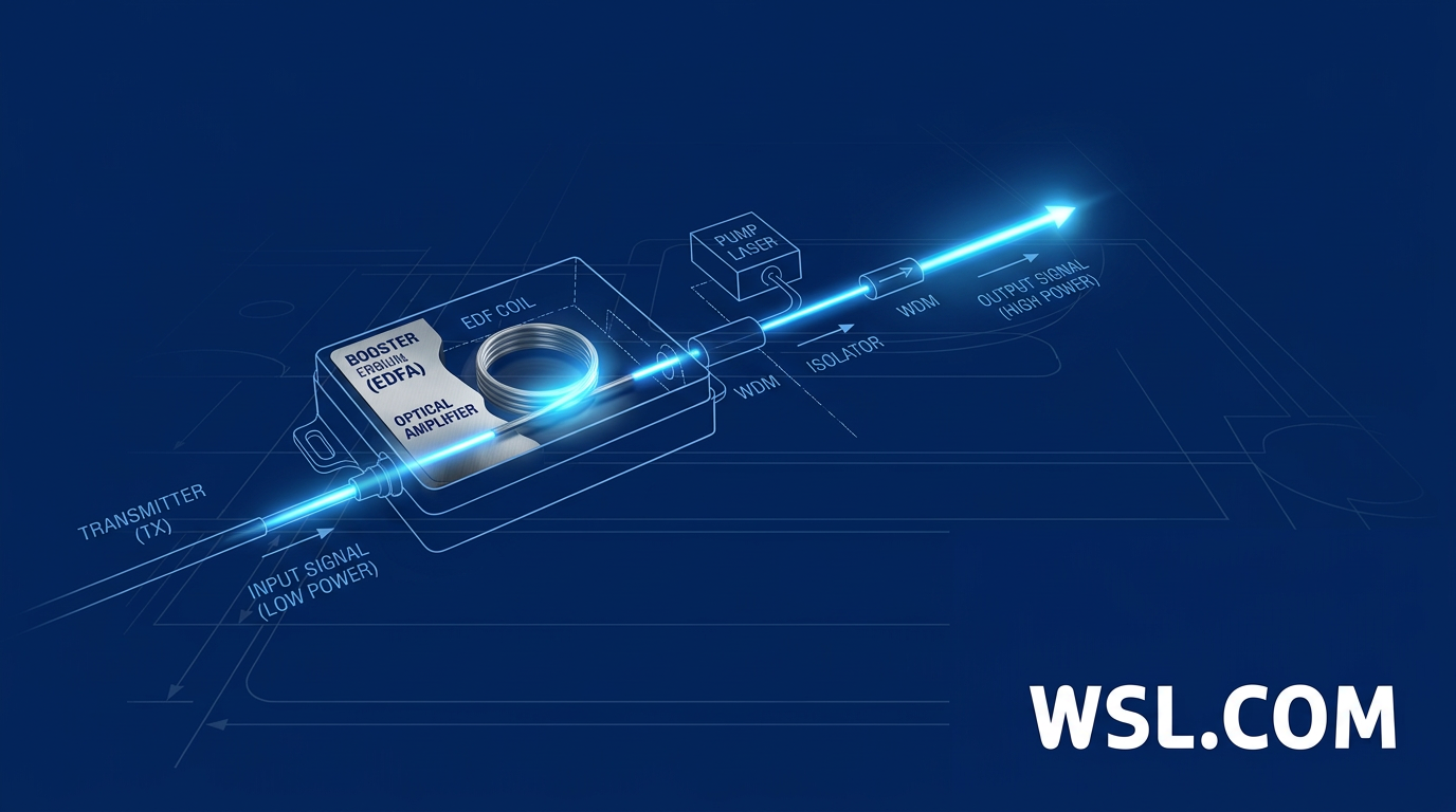
At its core, an EDFA works by passing the optical signal through a length of erbium-doped fibre that is energised by a pump laser diode; the pump excites the erbium ions, and incoming signal photons trigger stimulated emission, producing amplified copies of themselves in the same wavelength and phase.
Three placement roles: booster, in-line, pre-amplifier
EDFA technology underpins all three functional placement roles used in modern fibre links. The roles are not defined by technology — they are defined by where in the link the amplifier sits and what problem it is solving at that position.
| Role | Position in link | Primary function | Design priority |
|---|---|---|---|
| Booster amplifier | Immediately after transmitter or WDM MUX | Raise launch power before signal enters the fibre span | Maximum output power |
| In-line amplifier | Mid-span, between fibre sections | Compensate for accumulated span loss; restore signal to usable level | Gain flatness and OSNR maintenance |
| Pre-amplifier | Immediately before receiver | Boost weak received signal to improve detection sensitivity | Minimum noise figure |
Side-by-side comparison of the three EDFA placement roles by position, primary function, and design priority — giving readers the classification framework the rest of the guide builds on.
The table makes the underlying logic visible: each role faces a fundamentally different signal condition. The booster receives the signal at its strongest point in the entire link; the in-line amplifier receives a signal already weakened by one or more fibre spans; the pre-amplifier receives the weakest signal in the system, just before the receiver's photodetector.
Those signal conditions directly shape each role's design priorities. A booster amplifier — placed immediately after the transmitter, or after the multiplexer in WDM systems — is engineered to deliver high output power, setting the launch power that determines how far the signal can travel before it falls below a usable level. An in-line amplifier mid-span must maintain signal quality across multiple cascaded stages. A pre-amplifier at the receiver end prioritises a low noise figure above all else, since noise added at that stage directly degrades detection.
All three placement roles are typically implemented using EDFA technology, yet their design priorities diverge sharply. The booster, in-line amplifier, and pre-amplifier are not different amplifiers in kind — they are the same core technology optimised for three distinct positions in the link. Placement is the variable that changes everything.
This guide focuses on the booster role. The in-line amplifier and pre-amplifier appear in later sections only where they offer useful contrast against booster-specific design choices.
With the three placement roles defined, the natural next question is why the transmitter end is chosen as the point of amplification — and what engineering logic makes boosting at the source, before any attenuation has accumulated, the strategic decision it is.
Why Amplify at the Transmitter End?
Every kilometre of single-mode fibre costs the signal power — roughly 0.2 dB/km in the C-band, accumulating relentlessly from the moment light enters the glass. The question facing every link designer is not whether to fight this loss, but where along the span to fight it. That choice has consequences that ripple through every aspect of system performance.
Attenuation is not a one-time penalty. It is a continuous, progressive degradation: signal-to-noise ratio deteriorates with every additional kilometre, and a signal launched at a given power level will eventually fall below the receiver's sensitivity threshold if nothing intervenes.
The engineering framework that makes this concrete is the link budget — the total allowable optical power loss a system can sustain between transmitter and receiver before the signal becomes unrecoverable. Think of it as a finite reserve of decibels: every component in the path draws from it.
- Fibre span attenuation: The dominant draw on the budget, accumulating at approximately 0.2 dB/km across C-band in standard single-mode fibre.
- Splice losses: Each fusion splice adds a small but non-zero loss; over long spans with many splices, the aggregate is significant.
- Connector losses: Physical connectors introduce additional insertion loss at each interface point along the link.
- Component insertion losses: Passive components such as DWDM multiplexers contribute loss before the signal even enters the transmission fibre.
The booster amplifier addresses this budget problem at the most advantageous moment: before any of it has been spent. By raising the launch power baseline at the transmitter end, the booster directly expands the total budget available — more headroom means longer achievable spans, greater tolerance for component losses, or both.
The core logic is straightforward. At the transmitter end, the signal is at its strongest point in the entire link — no fibre attenuation has yet occurred, no noise has yet accumulated. Amplifying here means working with the best available input signal and setting the highest possible starting power from which the span's loss budget begins to be drawn down.
The further into the link amplification is deferred, the more attenuation the signal has already absorbed and the more noise has already accumulated. Amplifying a degraded signal is always less efficient than amplifying a strong one — the booster's transmitter-end placement is the direct consequence of that principle.
This is what separates the booster role from in-line amplification. An in-line amplifier compensates for loss that has already accumulated — it restores a degraded signal partway through the span. The booster, by contrast, sets the conditions from which the entire span begins. The booster determines the starting point; in-line amplifiers manage the consequences of that starting point as the signal travels.
Placing amplification at the transmitter end — before fibre attenuation begins — is not simply a convention. It is the only point in the link where the amplifier operates on the signal at its full strength, setting the power baseline from which the entire link budget is drawn.
In DWDM systems, there is an additional and highly practical driver for booster placement. The multiplexer (MUX) that combines multiple wavelength channels onto a single fibre introduces insertion loss before the combined signal even reaches the transmission span. Depending on technology and channel count, DWDM MUX insertion loss typically falls in the range of 2.5–5 dB for AWG-based devices, and 4–5 dB for thin-film filter designs at eight channels.
The booster, positioned immediately after the MUX, is therefore compensating for two distinct losses simultaneously: the MUX insertion loss and the attenuation the signal will accumulate over the fibre span ahead. Restoring launch power to the required level at this point is one of the primary practical reasons booster amplifiers are standard in DWDM network design.
Viewed at the system level, the choice of launch power — which the booster sets — is one of the most consequential decisions in link design. It determines the starting OSNR from which noise accumulates across all subsequent amplification stages, and it directly governs the achievable span reach before signal quality falls below the threshold for error-free reception.
That system-level consequence is precisely why the booster's performance characteristics are not arbitrary specifications — they flow directly from the engineering logic of transmitter-end placement. Understanding why the booster must deliver high launch power is the natural next step: what that demand actually requires from the amplifier's design is the subject of the following section.
Output Power: The Defining Design Requirement
Specify a booster amplifier by starting with gain, and you will almost certainly get the design wrong. Output power — expressed in dBm — is not merely the most important specification for a booster-configured EDFA; it is the specification from which every other design constraint follows. This is a distinction of design priority, not degree.
In-line amplifiers are optimised to balance gain against noise across a multi-span link. Pre-amplifiers are engineered around a single priority: minimising noise figure to recover a weak signal at the receiver. The booster's design logic is different in kind — its entire architecture is oriented around maximising the launch power it delivers into the fibre span.
That launch power is the starting point for the link's optical signal-to-noise ratio (OSNR) budget. The signal will attenuate progressively across the span, and the booster's output power sets the ceiling from which that attenuation begins. A higher launch power means the signal remains above the minimum acceptable OSNR threshold for a greater distance, directly extending the reach of the link before the first in-line amplifier or receiver.
Two forces at the transmitter end drive the demand for high output power. First, as established in the previous section, MUX insertion loss in WDM systems attenuates the multiplexed channels before they even enter the fibre span — flat-top AWG multiplexers can carry insertion losses in excess of 7.5 dB, and the booster must restore launch power to the required level after that loss. Second, the booster must establish sufficient power at the start of the span to sustain acceptable OSNR across its full length. Neither of these requirements is negotiable.
Typical output power ranges for booster configurations
Real-world booster EDFA specifications span a meaningful range, and the configuration type determines where on that range a given deployment sits. Standard booster configurations — covering the majority of metropolitan and regional long-haul deployments — achieve saturation output powers of up to 20 dBm, as reflected in manufacturer datasheets for C-band booster EDFAs. High-power designs, used in extended-reach and repeaterless applications, reach considerably further.
| Configuration Type | Typical Saturation Output Power | Representative Application |
|---|---|---|
| Standard booster EDFA | Up to 20 dBm | Metropolitan and regional long-haul links; post-MUX amplification in DWDM systems |
| Gain-flattened booster EDFA | Up to 23 dBm | C-band DWDM links requiring flat gain across the full channel plan |
| High-power booster EDFA | 23–27 dBm | Extended-reach links; repeaterless spans where intermediate amplification is impractical |
| Post-booster (cascaded) EDFA | Up to 27 dBm | Spans exceeding 200 km; used following a standard 17–20 dBm booster for additional launch margin |
Comparison of booster EDFA configuration types by saturation output power range and representative application, grounded in manufacturer and trade-press source data.
The jump from the standard 20 dBm tier to the 23–27 dBm high-power tier represents a qualitative shift in system reach. A post-booster delivering 27 dBm provides 7 dB of additional span budget over a standard 20 dBm amplifier — enough, according to Lightwave Online's analysis of advanced amplification techniques, to extend repeaterless link distances from around 200 km to beyond 350 km when combined with industry-standard transponders.
For engineers specifying a booster, the practical implication is direct: identify the required launch power at the fibre input — accounting for MUX insertion loss, span length, and the OSNR target at the far end — and use that figure to select the appropriate configuration tier. Gain and noise figure are then evaluated as supporting parameters, not co-equal constraints.
The contrast with the pre-amplifier role makes this hierarchy concrete. A pre-amplifier sits at the receiver end of the link, where the signal has already been attenuated across the full span. One published example places the booster output at 23 dBm and the corresponding pre-amplifier output at just 5 dBm — a difference of 18 dB that reflects the fundamentally different conditions each amplifier faces. The pre-amplifier's priority is noise figure, not output power; it must add as little noise as possible to a weak signal, not drive a high-power launch into glass.
For a booster amplifier, output power (in dBm) is the specification to fix first. Gain, noise figure, and wavelength range are all evaluated in terms of whether they support the required launch power — not as independent constraints of equal weight.
The output power demands that define the booster role have a direct internal consequence: they push the amplifier into an operating regime that in-line and pre-amplifier designs actively avoid. Understanding how that regime behaves — and why it is managed rather than prevented in a booster configuration — is the subject of the next section.
Explore Tailored EDFA Solutions for Your Network
Output power requirements vary by application. Our custom EDFAs are engineered to meet the specific demands of your link — from saturated output targets to thermal and form-factor constraints.

Gain Saturation in Booster Configurations: Managing, Not Avoiding
Most treatments of gain saturation in optical amplifiers frame it as a limit to be pushed back — a constraint that good design should minimise. In the booster context, that framing is wrong. A booster optical amplifier operating near or into saturation is not a stressed component approaching failure; it is a correctly specified amplifier doing exactly what it was designed to do.
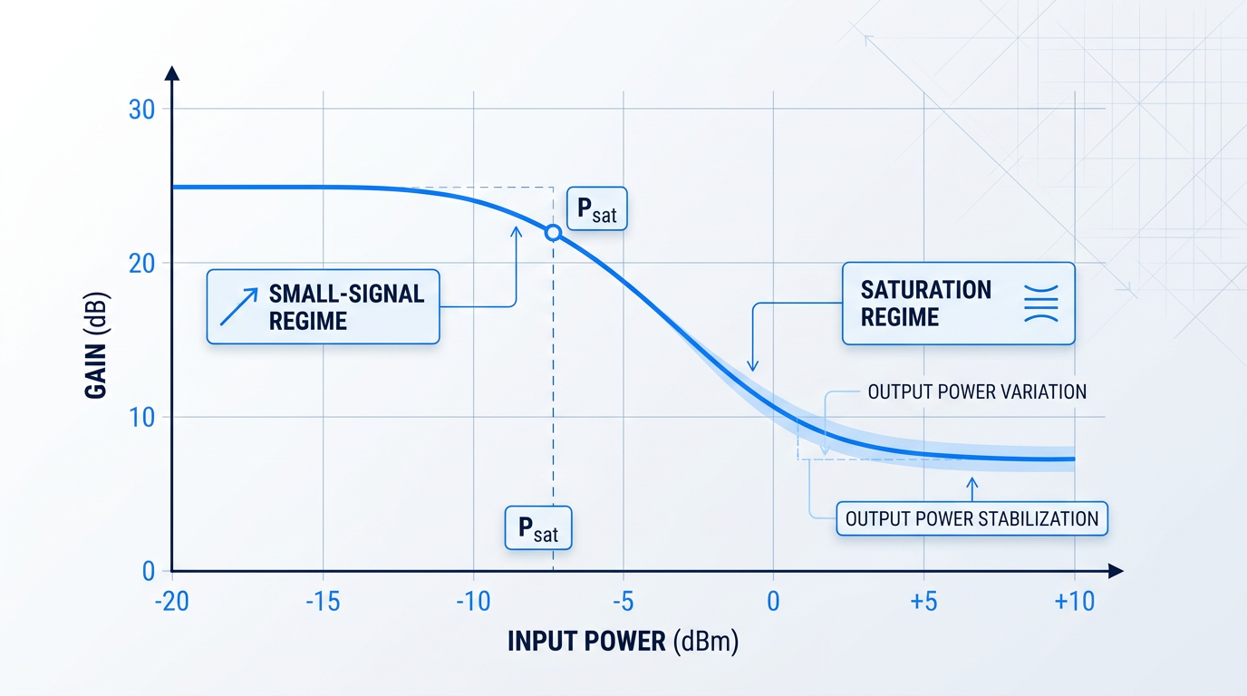
The physics is straightforward: as input power rises beyond the small-signal regime, the amplifier's gain begins to fall. The erbium-doped gain medium can only sustain a finite population inversion, and at high input powers the signal extracts energy from that inversion faster than the pump laser can replenish it.
The operational consequence is gain compression: each additional decibel of input power yields progressively less output power gain, until the amplifier's output approaches a ceiling. This is the saturation regime, and it is characterised by a single key specification.
Saturation output power (P_sat) is defined as the output power at which the amplifier's small-signal gain has been compressed by 3 dB — meaning the gain has halved relative to its low-input-power value. P_sat marks the practical ceiling for continuous-wave power extraction and is the specification engineers should use to define a booster's usable operating envelope.
When evaluating or selecting a booster amplifier, P_sat is the specification that defines whether the device can actually sustain the output power the link budget demands under real operating conditions, not just under idealised low-input-power test conditions.
At the transmitter end of a link, the booster receives signals directly from the transmitter output or multiplexer — input power levels that are inherently high relative to what an in-line amplifier sees after a fibre span has attenuated the signal. This is precisely what pushes the booster toward its saturation regime under normal operation.
The contrast with the other placement roles, established earlier, is instructive here. In-line amplifiers receive signals that have already been attenuated over a fibre span, so they may operate with more headroom from saturation depending on span loss and channel loading. Pre-amplifiers, positioned at the receiver end, handle very weak signals and are deliberately kept well clear of deep saturation — because saturation in a pre-amplifier degrades noise performance at exactly the point where noise figure is most critical.
The booster is the one placement role where proximity to saturation is not a trade-off to be managed reluctantly. It is the expected, specified operating condition — and system designers who treat it otherwise are working from the wrong model.
Gain Compression as a Stabilising Design Property
Operating in saturation carries a counter-intuitive but practically valuable consequence: the amplifier's output power becomes relatively insensitive to variations in input power.
In the linear regime, a change in input power produces a proportional change in output power. In saturation, the same input variation produces a much smaller output variation — the compressed gain absorbs the fluctuation. Experienced system engineers exploit this property deliberately.
In constant-power mode operation, a saturated booster tends to hold its output power more stably against input fluctuations than a linear amplifier would. Rather than a side effect to be tolerated, this output stability is a feature that simplifies power management at the transmitter end of the link.
There is one complication in WDM booster configurations that engineers must account for specifically: as channels are added or dropped during network reconfiguration or partial loading, the total composite input power to the booster changes.
Each shift in channel loading moves the amplifier's operating point relative to saturation, affecting per-channel gain and output power in ways that must be characterised across the full range of expected loading conditions — not just at full channel count. The broader WDM implications of this, including per-channel power management and automatic gain and power control, are addressed in a later section.
With saturation behaviour understood as a managed operating condition rather than a fault state, the next performance parameter worth examining is noise figure — and specifically why the noise figure constraint looks fundamentally different for a booster than it does for a pre-amplifier.
Noise Figure in Booster Amplifiers: Why the Constraint Differs
Ask most engineers which amplifier parameter matters most, and noise figure comes up immediately — and for good reason. But applying that instinct uniformly across all amplifier placements is one of the most common specification errors in optical network design. For the booster optical amplifier, the noise figure constraint operates under fundamentally different rules, and understanding why is what separates a correctly specified booster from an over-engineered one.
What Noise Figure Actually Measures
Noise figure (NF) is the ratio of input signal-to-noise ratio to output signal-to-noise ratio, expressed in decibels: NF = 10 log₁₀(F), where F is the noise factor.
In practical terms, NF quantifies how much an amplifier degrades the signal-to-noise ratio as the signal passes through it — a higher figure means the amplifier itself is contributing more noise to the output.
The theoretical floor for a phase-insensitive linear amplifier is 3 dB — a limit set by the physics of optical amplification, not by engineering shortcomings. In practice, well-designed EDFA configurations achieve noise figures in the range of 4–6 dB, with the best low-noise designs approaching the lower end of that range.
Placement Changes the Noise Figure Calculus
The booster sits immediately after the transmitter, receiving the signal at its highest power level anywhere in the entire link — before any fibre attenuation has occurred.
At this point, the signal-to-noise ratio is at its peak. The absolute noise contribution from the booster, while real, is small relative to the signal power it is amplifying — and that noise is subsequently diluted across the full noise budget that accumulates over multiple fibre spans and in-line amplifiers.
The OSNR degradation introduced by the booster is therefore a minor fraction of the total noise accumulated by the time the signal reaches the receiver. The NF constraint is genuinely relaxed — not as a design compromise, but as a direct consequence of where in the link the booster operates.
A booster amplifier's relaxed noise figure requirement is not a trade-off the designer accepts reluctantly. It is a physical consequence of the booster receiving the signal at its strongest point in the link, where the noise contribution is smallest relative to the total system noise budget.
The Pre-Amplifier Contrast
The contrast with the pre-amplifier makes this argument precise. The pre-amplifier receives the signal after it has traversed the full span — at its weakest point in the entire link, having suffered maximum attenuation.
Any noise the pre-amplifier adds at this stage has a disproportionate impact on the final OSNR: there is no subsequent amplification to recover from it, and the receiver sees the pre-amplifier's noise contribution in full.
As Lightwave Online's amplifier evaluation guidance notes directly, output power is the most important measurement when EDFAs are used as boosters, while noise figure testing assumes prime consideration for in-line and pre-amplifier roles — particularly in long-haul links where any noise is magnified by all subsequent amplifiers.
The same NF figure that is entirely acceptable in a booster would be unacceptable in a pre-amplifier. These are not the same specification applied to different hardware — they are different specifications serving different engineering constraints.
Pump Architecture: The Engineering Mechanism
The NF versus output power trade-off in EDFA design is realised through the choice of pump wavelength and direction.
Forward pumping at 980 nm — where the pump propagates in the same direction as the signal — produces a high degree of population inversion at the input of the erbium-doped fibre, where the signal is weakest. This minimises amplified spontaneous emission at the critical early stage of amplification, yielding the lowest achievable noise figure.
Backward pumping at 1480 nm — counter-propagating relative to the signal — concentrates pump power at the output end of the gain medium, where the signal is strongest. This delays the onset of gain saturation and maximises output power, but at the cost of a higher noise figure compared to forward pumping.
| Configuration | Pump Wavelength | Pump Direction | Primary Outcome | Preferred Application |
|---|---|---|---|---|
| Forward pumping | 980 nm | Co-propagating (signal direction) | Minimum noise figure; high population inversion at fibre input | Pre-amplifier |
| Backward pumping | 1480 nm | Counter-propagating (opposite to signal) | Maximum output power; delayed gain saturation at fibre output | Booster amplifier |
| Hybrid pumping | 980 nm + 1480 nm | Bidirectional | Low noise figure combined with high output power | High-performance in-line amplifier |
Comparison of forward and backward EDFA pump configurations across the parameters that determine booster versus pre-amplifier suitability.
The table reflects a clear design logic: the pump configuration follows directly from the amplifier's placement role. Backward 1480 nm pumping is not a compromise forced on booster designs — it is the configuration that best serves the booster's primary requirement of maximum output power, given that the NF constraint is already relaxed by placement.
Hybrid bidirectional pumping, combining 980 nm forward and 1480 nm backward stages, can achieve both low noise figure and high output power simultaneously — but this is the architecture of choice for high-performance in-line amplifiers, not the typical booster configuration where the added complexity is unnecessary.
The Specification Implication for Engineers
Engineers who over-prioritise noise figure when specifying a booster amplifier are optimising for the wrong parameter.
Imposing an unnecessarily tight NF requirement on a booster may force the design toward forward 980 nm pumping — precisely the configuration that trades away output power to achieve low noise. Since output power is the booster's defining constraint, this is a specification error with real consequences: reduced launch power, shorter reach, or a more expensive design that delivers no system-level benefit.
The booster's NF tolerance is not a weakness to be engineered around. It is a feature of its position in the link, and treating it as such is what allows the design to be optimised for what actually matters.
The pump architecture choices that give the booster its output power advantage — particularly backward 1480 nm pumping at high drive levels — also generate a significant thermal load within the gain medium. Managing that heat is the practical engineering challenge that follows directly from high-power booster operation, and it is the subject of the next section.
Thermal Management: The Constraint That Scales With Power
The high output power levels that define booster amplifier operation do not exist only in the signal domain — they have a direct physical consequence that every deployment must account for: heat.
That heat originates primarily in the pump lasers and the erbium-doped fibre itself, where the power conversion process is inherently imperfect.
Pump photons excite erbium ions into higher energy states, stimulated emission produces the amplified signal, and non-radiative relaxation accounts for the energy that does not become useful signal output — that residual energy dissipates as heat within the device.
The thermal load scales directly with output power: a booster operating at 27 dBm generates substantially more heat than one running at 20 dBm, and the gap is not trivial.
Why Temperature Sensitivity Is a Reliability Problem
Pump laser diodes are among the most temperature-sensitive components in an EDFA — their efficiency, threshold current, and emission wavelength all shift with operating temperature.
More critically, sustained elevated temperature accelerates degradation mechanisms inside the laser chip, shortening operational lifetime well below the unit's rated MTBF.
This is not a marginal concern: a booster amplifier that consistently runs hot will fail earlier than its datasheet suggests, and the failure mode is progressive rather than sudden — output power drifts, link margin erodes, and the fault is often attributed to the wrong cause.
Thermoelectric Coolers: The Standard Solution and Its Complication
The established engineering response is the thermoelectric cooler (TEC) — a solid-state device that actively pumps heat away from the pump laser chip, holding the laser junction at a controlled set-point temperature regardless of ambient conditions.
TECs are effective at solving the local temperature problem, but they introduce a system-level complication that is easy to underestimate.
A thermoelectric cooler keeps the pump laser cool by moving heat to its hot side — that heat still has to go somewhere. The enclosure, heat sink, and rack airflow must absorb it, or the TEC's benefit is negated at the system level.
TECs consume electrical power and generate heat on their hot side, which must be carried away by the enclosure's heat dissipation path — typically a combination of heat sinks and forced airflow through the rack.
In a high-power booster, this means the thermal management system is layered: TEC handles the pump laser locally, but the enclosure and rack environment must handle the aggregate load.
Rack-Mount Ventilation as a Deployment Prerequisite
For rack-mount booster amplifiers, rack-mount ventilation is not an installation convenience — it is a functional requirement that should be specified before the equipment arrives on site.
- Airflow direction and volume: Front-to-back or side-to-side airflow must be confirmed for the specific chassis; inadequate volume prevents heat sinks from shedding load effectively.
- Clearance around the unit: Blocked adjacent slots or tight rear-panel cable bundles restrict exhaust airflow and raise internal temperatures, even when the rack itself is ventilated.
- High-density rack configurations: Multiple amplifiers in adjacent 1U slots create thermal stacking — each unit's exhaust becomes the next unit's intake air if spacing is not planned.
- Ambient temperature compliance: The equipment room's ambient temperature, including seasonal peaks and cooling system failure scenarios, must fall within the amplifier's rated operating range.
Each of these factors compounds the others: a high-density rack in a room that runs warm at the top of its cooling cycle, with cable management that restricts rear exhaust, is a configuration that will stress even a well-designed unit.
Higher output power booster designs often carry a narrower specified operating temperature range than lower-power units, because the thermal headroom between normal operation and the component's rated maximum is tighter.
Engineers deploying into environments without reliable climate control — or with significant seasonal temperature variation — should verify the amplifier's rated range explicitly against the worst-case ambient, not the nominal.
Treating thermal management as a specification requirement rather than an installation detail is the discipline that separates robust deployments from ones that degrade quietly over time.
With the physical deployment picture established, the guide now turns to a different layer of complexity: what happens to booster amplifier behaviour when it must serve not a single channel, but a full WDM comb of wavelengths simultaneously.
Booster Amplifiers in WDM Systems
Everything covered so far — output power, gain saturation, noise figure, thermal load — describes the booster amplifier as a single-channel device. The real-world test is more demanding: in virtually every long-haul EDFA deployment, the booster sits immediately after the multiplexer and must simultaneously amplify dozens of independent channels, each on a distinct wavelength across the C-band. That multi-channel reality introduces engineering challenges that simply do not exist in single-channel operation.
In a DWDM system, the MUX combines all active channels into a single composite signal before handing it to the booster. The amplifier sees not one wavelength but a full spectral comb — potentially 40, 80, or more channels — and must deliver adequate, balanced amplification to every one of them simultaneously.
Gain Flatness: The WDM-Specific Requirement
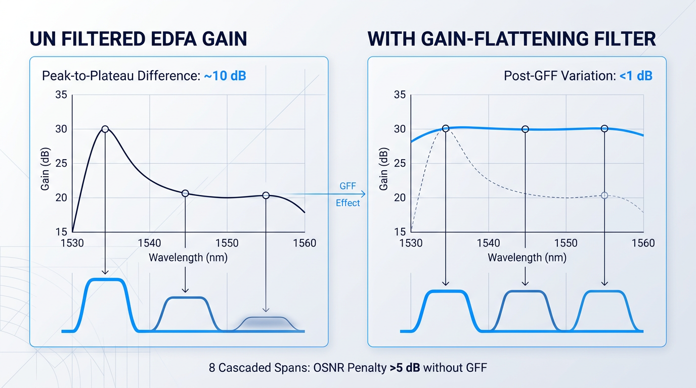
An untreated EDFA does not amplify all wavelengths equally. The erbium gain profile across the C-band is inherently non-uniform: the gain peaks sharply in the 1530–1535 nm region and is considerably lower across the 1540–1560 nm plateau, with the difference between peak and plateau potentially exceeding 10 dB at low input powers.
This gain tilt is not a minor inconvenience in a WDM system — it is a compounding problem. Each amplifier span adds its own gain non-uniformity to the accumulated imbalance from all preceding spans. Channels sitting at gain-peak wavelengths arrive at the receiver with substantially better OSNR than channels at lower-gain wavelengths, creating a systematic disparity that worsens with every cascaded amplifier stage.
Research published in Lightwave Online quantifies the consequence: with a gain flatness (ripple) of just 1.8 dB per amplifier, the cumulative OSNR penalty exceeds 5 dB after only eight transmission spans — enough to push bit-error rates beyond acceptable limits without any other impairment present.
The standard engineering response is the gain-flattening filter (GFF): a passive optical component that introduces wavelength-dependent attenuation, suppressing the higher-gain wavelengths to equalise channel powers across the operating band. Commercially available amplifiers with GFFs integrated between dual gain stages can achieve gain variation below 1 dB across the full C-band, with some designs reaching 0.5 dB uniformity. The Telcordia GR.1312 generic requirements specify ±1 dB gain variation at the amplifier output as the target for WDM deployments.
Critically, a GFF is a passive, fixed optical component integrated into the amplifier module at the design stage — it is not field-adjustable. Gain flatness is therefore a fixed characteristic of the amplifier design, not a parameter that can be tuned after installation. This is the core reason why gain flatness must be specified upfront, before amplifier selection, rather than addressed post-deployment.
Channel Loading and Saturation Under Dynamic Conditions
As discussed in the context of gain saturation, a booster amplifier is designed to operate near or into saturation — that is its normal operating point. In a WDM system, the saturation behaviour discussed earlier becomes significantly more complex because the total optical power entering the amplifier equals the sum of all active channel powers.
This matters acutely in networks with ROADMs or dynamic provisioning, where channel loading is not static. As channels are added, total input power rises and the amplifier is pushed deeper into saturation; as channels are dropped, total input power falls and the amplifier moves toward the linear regime. Each shift changes the per-channel gain and per-channel output power for all surviving channels.
A peer-reviewed dataset from the Journal of Optical Communications and Networking, drawn from 202,752 gain spectrum measurements across 16 commercial ROADM booster and pre-amplifier EDFAs under varying channel-loading configurations, confirms that gain settings and channel-loading conditions interact in ways that are not trivially predictable from single-channel characterisation alone.
The practical implication for specification is that a booster must be evaluated across its full expected range of channel loading conditions — from minimum loaded to fully loaded — not just at the nominal operating point. An amplifier that performs adequately at full channel count may deliver unacceptable per-channel power variation when the network is partially loaded.
Per-Channel Power: The Metric That Actually Matters
Most booster amplifier datasheets lead with total composite output power — the aggregate optical power delivered at the amplifier output across all channels. This figure is necessary but insufficient for WDM system design. The metric that determines whether each channel survives the full span with adequate signal quality is per-channel output power: the power each individual wavelength receives at the amplifier output.
The relationship between the two is governed by a straightforward scaling formula that every WDM system designer must apply when reading a booster datasheet.
P_total (dBm) = P_per_channel (dBm) + 10·log10(N), where N is the number of active channels. Example: a booster with 23 dBm total output power serving 16 channels delivers approximately 11 dBm per channel (23 − 10·log10(16) ≈ 23 − 12 = 11 dBm). For 40 channels, that same 23 dBm total yields roughly 7 dBm per channel.
This formula makes explicit what datasheet headline figures obscure: per-channel power decreases logarithmically as channel count increases for any fixed total output power. A booster that appears adequately powered for a 16-channel system may be marginal for a 40-channel deployment using the same total output specification.
Per-channel power must sit within a bounded operating window. The lower bound is set by the minimum power needed to sustain acceptable OSNR over the full span length. The upper bound is the nonlinear threshold of the transmission fibre — the per-channel power level beyond which fibre nonlinearities begin to degrade signal quality.
The nonlinear effects of concern are stimulated Raman scattering (SRS), cross-phase modulation (XPM), and four-wave mixing (FWM). SRS creates a wavelength-dependent power tilt across the channel comb; XPM and FWM generate crosstalk and ghost channels that corrupt signal integrity. All three scale with per-channel launch power, making the nonlinear threshold a hard ceiling that per-channel power must not exceed.
AGC and APC: Maintaining Stability Under Dynamic Loading
The channel loading dynamics described above create a practical control problem: how does the amplifier maintain stable per-channel power as the number of active channels changes? Two operational control modes address this — automatic gain control (AGC) and automatic power control (APC) — and they do so in fundamentally different ways.
- Automatic Gain Control (AGC): Maintains constant amplifier gain regardless of input power fluctuations. Preferred in terrestrial WDM networks to limit undesired power dynamics when channels are added or dropped.
- Automatic Power Control (APC): Maintains constant total output power regardless of gain or input variations. Per-channel power adjusts as channel count changes, but total output remains bounded.
The distinction between the two modes has real consequences under dynamic loading. Under AGC, if channels are dropped, the amplifier maintains its gain — which means the surviving channels each receive more power, potentially approaching the nonlinear threshold. Under APC, total output power is held constant, so surviving channels share the same power pool and per-channel power rises more moderately.
Neither mode is universally superior: the right choice depends on the network architecture, the expected range of channel loading, and the margin available between the minimum OSNR floor and the nonlinear ceiling. What matters for specification purposes is that the booster supports switchable AGC and APC modes — commercial products such as those documented in FS.com datasheets confirm that operation mode switching between AGC and APC via network management software is a standard feature of WDM EDFA boosters.
Gain flatness, per-channel power budget, and control mode are not parameters to verify after the amplifier is installed — they are design requirements to be locked into the specification before selection. An amplifier that meets total composite output power requirements but has poor gain flatness or no AGC/APC capability will underperform in any real DWDM deployment. With these WDM-specific requirements understood, the engineering logic of booster amplifier specification comes into full view — and that is where this guide closes.
Custom EDFAs Built for Real Network Demands
From single-channel links to multi-wavelength WDM deployments, booster performance depends on the right EDFA specification. Explore tailored EDFA solutions designed around your output power, gain, and application requirements.

Conclusion
Specifying a booster amplifier: what the engineering logic tells you
Placement is the explanatory frame: once you understand that the booster optical amplifier sits at the transmitter end, every other performance requirement follows from that fact rather than standing as an independent design concern.
When specifying, anchor on output power first — gain, noise figure, saturation output power, and wavelength range are the verification layer, with gain flatness added for WDM deployments.
The booster is one element of a larger amplification chain, and how it hands off to in-line amplifiers and pre-amplifiers is where the design thinking naturally goes next.
Frequently asked questions about booster optical amplifiers
Practical questions about the booster amplifier's role, design priorities, and operating principles — answered directly for engineers and network designers.
The fundamental difference is placement in the link, and the design priority that follows from it. A booster amplifier sits immediately after the transmitter and is optimised for high saturation output power — its job is to launch the strongest possible signal into the fibre span. A pre-amplifier sits immediately before the receiver and is optimised for the lowest possible noise figure — its job is to recover a signal that has been attenuated across the full span. The reason placement drives design priority is straightforward: the booster receives the signal at its strongest point, before any fibre loss has accumulated, so a slightly elevated noise figure causes negligible degradation. The pre-amplifier receives it at its weakest point, after the full span has taken its toll, so noise figure is the non-negotiable constraint — every fraction of a dB matters for bit error rate at the receiver.
Standard booster EDFA configurations typically achieve saturated output powers of 20 dBm or more. High-power designs for extended-reach or multi-channel DWDM applications can reach 23–27 dBm — Lightwave Online notes that telecom-grade post-boosters can deliver up to 27 dBm for demanding long-span scenarios. Output power is the defining specification for the booster role because the amplifier must overcome not just fibre attenuation but also the insertion loss of the DWDM multiplexer before the signal even enters the fibre. In dense WDM systems, that MUX loss can be significant, and as channel count scales, maintaining adequate per-channel launch power requires the booster to deliver correspondingly higher total output.
Not always — but typically yes in DWDM deployments. For single-channel, short-reach links where the transmitter's output power is sufficient to meet the receiver's sensitivity after all span losses, a booster may be unnecessary. The decision is driven by link budget analysis: if the actual link loss falls within the transceiver's power budget, no amplification is needed. In DWDM systems, however, the multiplexer introduces significant insertion loss before the combined signal enters the fibre. The booster compensates for this loss and restores launch power to a level that sustains acceptable signal quality across the span. Treating the booster as optional rather than mandatory is correct — but in practice, most multi-channel long-haul links require one.
P_sat (saturation output power) is defined as the output power at which the amplifier's small-signal gain has been compressed by 3 dB — it represents the practical ceiling for continuous-wave power extraction from the device. For booster amplifiers specifically, P_sat is a critical selection parameter because boosters routinely operate near or into saturation as a normal operating condition, not a fault state. The high input powers typical at the transmitter end push the amplifier into the saturation regime by design. An engineer specifying a booster must verify that P_sat meets or exceeds the required launch power: if P_sat falls short, the amplifier cannot sustain the needed output in continuous operation, regardless of its small-signal gain rating. P_sat should be treated as the binding constraint on booster selection, not an afterthought.
An optical amplifier boosts the power of an optical signal directly in the optical domain, without converting it to an electrical signal first. This allows it to compensate for power loss caused by fibre attenuation and component insertion losses — such as the MUX/DEMUX losses in WDM systems — enabling signals to travel long distances without optoelectronic regeneration. The EDFA (erbium-doped fibre amplifier) is the dominant technology for this function in long-haul and metro networks.
An EDFA works by passing the optical signal through a length of fibre whose core is doped with erbium ions (Er³⁺). A pump laser — typically operating at 980 nm or 1480 nm — excites the erbium ions to a higher energy state, establishing a population inversion. When signal photons in the C-band (1530–1565 nm) pass through the doped fibre, they stimulate the excited ions to emit additional photons at the same wavelength and phase, amplifying the signal via stimulated emission. This process occurs entirely in the optical domain, preserving the signal's format, modulation, and bit rate without any electrical conversion.
The C-band (Conventional band) spans approximately 1530–1565 nm. EDFA boosters operate there because two critical properties align at these wavelengths. First, erbium-doped fibre has its gain window in this range — the Er³⁺ ions amplify most efficiently at C-band wavelengths via stimulated emission. Second, standard silica single-mode fibre reaches its minimum attenuation of approximately 0.2 dB/km in the same region, meaning signals travel furthest with least loss at these wavelengths. The coincidence of the EDFA gain window and the fibre loss minimum made the C-band the natural foundation for long-haul optical transmission and DWDM systems — a single EDFA can simultaneously amplify dozens of WDM channels, all within this window.