

Introduction
If you are designing or evaluating amplification for a satellite-to-ground link, an inter-satellite optical terminal, or a terrestrial wireless optical system, this guide is written for you.
Good technical resources on free space optical amplifiers exist, but they tend to live in separate silos: academic papers that go deep on one technology, commercial datasheets that skip the trade-offs, or fibre-optic guides that treat FSO as a footnote.
The free-space environment changes the engineering problem in ways that fibre-optic assumptions simply do not prepare you for.
What follows consolidates the technology landscape, the performance trade-offs, the operational demands, and the emerging frontier of coherent beam combining into one practically grounded resource.
TL;DR
Choosing an FSO amplifier is not primarily a question of output power — it is a question of which technology can meet the full set of demands the free-space environment imposes. The right answer depends on link geometry, deployment platform, and operational conditions that fibre-optic design practice was never built to address.
This article covers:

EDFA, SOA, and fibre laser amplifiers compared
Output power, SWaP, radiation tolerance, ruggedisation
Atmospheric impairments and amplifier design implications
Noise figure and ASE: signal quality vs. gain
Coherent beam combining for FSO power scaling
What Is a Free Space Optical Amplifier?
Take a fibre-optic amplifier out of its rack, point its output into open air or across hundreds of kilometres of space, and the engineering problem changes completely. The propagation physics are different, the loss regime is different, and the performance demands on the amplifier are of a different order entirely. Understanding why starts with a precise definition of what a free-space optical amplifier actually is — and what distinguishes it from the fibre-optic amplifiers that inspired it.
An optical amplifier is a device that amplifies a light signal directly, without first converting it to an electrical signal and back again. The underlying mechanism is stimulated emission in a gain medium: incoming photons trigger the emission of additional photons with the same wavelength, phase, and direction, producing net optical gain.
This is the same fundamental process that drives a laser, but configured differently — the gain medium amplifies an input signal rather than generating one from spontaneous emission noise. The distinction from electronic repeaters matters: optical amplifiers preserve the signal in the optical domain, enabling much higher data rates and avoiding the latency and complexity of optoelectronic conversion.
A free-space optical amplifier is an optical amplifier deployed within a communication link where the signal propagates through open air or the vacuum of space, rather than through a guided medium such as optical fibre or an integrated waveguide. The amplifier itself may be internally fibre-based — an erbium-doped fibre amplifier (EDFA) housed inside a satellite terminal is still a free-space optical amplifier — but its defining characteristic is its role at the boundary of a free-space beam, not a fibre-to-fibre connection.
The principal FSO link types where these amplifiers are deployed include satellite-to-ground links, optical inter-satellite links (OISLs) connecting spacecraft across thousands of kilometres of vacuum, and terrestrial wireless optical links spanning urban or campus-scale distances.
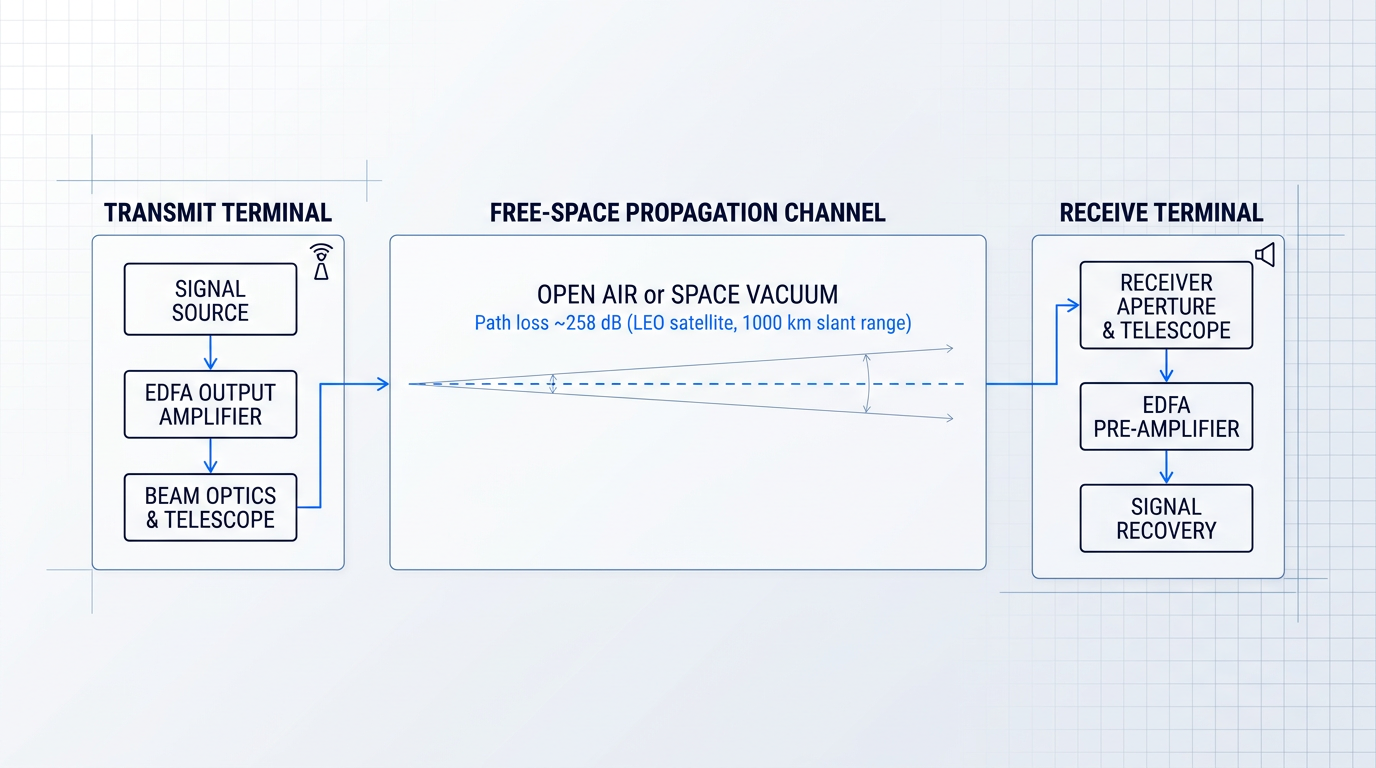
The free-space propagation channel imposes fundamentally different demands on an amplifier compared to a guided-wave system. The core issue is free-space path loss: optical power reaching a receiver aperture falls with the square of link distance — the inverse-square law — so even a modest increase in range produces a dramatic reduction in received power.
Beam divergence compounds this further. Even a tightly collimated laser beam spreads as it propagates, so only the fraction of the transmitted beam that falls within the receiver aperture contributes to the received signal. Over satellite link distances, this geometric loss alone can reach into the hundreds of decibels — the IEEE INGR Optics White Paper describes FSO link loss as reaching "100s of dBs" with very few photons remaining to capture at the receiver.
To put this in context: single-mode silica fibre used in telecommunications has a propagation loss of approximately 0.2 dB/km in the 1.5-µm spectral region, meaning even 100 km of fibre leaves roughly 1% of the original power at the receiver. Free-space geometry over a LEO satellite link at around 1,000 km slant range produces a range loss of approximately −258 dB before aperture gains are applied — a figure drawn directly from the NASA TBIRD mission link budget.
In a fibre link, the amplifier compensates for a low, distributed, and predictable loss — around 0.2 dB/km in the C-band. In an FSO link, it must overcome a geometric path loss that can reach hundreds of decibels, concentrated at a single point in the signal chain. The amplifier's output power requirement is not incrementally higher; it is categorically different.
This physical reality is why FSO amplification constitutes a genuinely distinct engineering discipline, not simply a repackaging of fibre-optic amplifier technology. The free-space environment imposes requirements that either do not arise in guided-wave systems, or do not arise in the same form.
- Beam quality preservation: The amplified output must maintain a near-diffraction-limited beam suitable for projection through a telescope into free space. This is a design constraint, not a given.
- SWaP constraints: Space and airborne FSO terminals must meet tight size, weight, and power budgets that have no equivalent in rack-mounted ground telecom infrastructure.
- Radiation tolerance: Satellite-borne amplifiers operate in ionising radiation environments that degrade optical fibre and semiconductor components over mission lifetimes.
- Ruggedised packaging: Terrestrial and airborne FSO links expose amplifiers to vibration, thermal cycling, and harsh conditions beyond standard telecom-grade specifications.
Taken together, these constraints explain why engineers working on FSO amplification cannot simply adapt a fibre-optic amplifier from a ground-based telecom application and expect acceptable results. Each requirement demands deliberate design choices — and the interaction between them (for instance, achieving high output power within a tight SWaP envelope while maintaining radiation tolerance) is where the real engineering challenge lies.
One factor that shapes nearly every FSO amplifier design is wavelength. The 1550 nm band dominates FSO systems for three reinforcing reasons: it falls within a favourable atmospheric transmission window (as confirmed by ITU-R P.1814, which notes that laser wavelengths are typically selected to fall inside atmospheric transmission windows where clear-air attenuation is negligible), it benefits from higher permissible transmit powers under eye-safety considerations compared to shorter wavelengths, and it aligns directly with the mature EDFA ecosystem developed for fibre-optic telecommunications — making pump lasers, isolators, and gain fibre commercially available and well-characterised.
With the foundational definition established, the next question is where in the FSO signal chain amplification is applied and what functional role it serves at each point — which is where the architecture discussion begins.
Optical Amplification in FSO Link Architecture
Where you place an amplifier in an FSO link is not a detail to resolve late in the design process — it is one of the first architectural decisions, because placement determines which performance parameters matter most and, by extension, which amplifier technologies are even viable.
A free space optical amplifier can serve three functionally distinct roles within the FSO signal chain, each imposed by a different physical reality of the link, and each demanding a different primary performance characteristic from the amplifier that fills it.
- Transmit-side power booster: Positioned before the transmit telescope; drives sufficient optical power into the free-space channel. Primary requirement: maximum output power to close the link budget.
- Receive-side optical pre-amplifier: Positioned before the photodetector; amplifies a weak incoming signal to a processable level. Primary requirement: low noise figure to preserve receiver sensitivity.
- In-line relay amplifier: Deployed at intermediate nodes in long terrestrial links or relay satellite architectures. Requires a balance of output power and noise performance.
The transmit-side booster exists because of a fundamental physical reality: free-space path loss scales with the square of link distance.
That inverse-square relationship is unforgiving — doubling the link range quadruples the path loss, demanding a corresponding increase in transmitted optical power just to maintain the same received signal level, before atmospheric margin is even considered.
The engineering objective this drives is closing the link budget: ensuring that transmitted power, accounting for all free-space and system losses, still delivers a received signal that exceeds the detector's sensitivity threshold with adequate margin.
This is why FSO power-booster amplifiers must operate at output levels that far exceed what fibre-telecom amplifiers are typically designed for — the free-space channel simply consumes far more power than a guided fibre span of comparable length.
On the receive side, the signal arriving at the terminal has traversed the full free-space path and may be orders of magnitude weaker than the detection threshold of a practical photodetector operating without amplification.
A receive-side optical pre-amplifier boosts this weak signal before it reaches the detector, but the amplification itself introduces noise — and a noisy pre-amplifier degrades receiver sensitivity by raising the noise floor alongside the signal, effectively narrowing the margin above the detector's minimum detectable power.
This is why noise figure is the critical performance parameter for pre-amplifiers: a lower noise figure means the amplifier adds less noise relative to the signal it amplifies, preserving the sensitivity advantage that optical pre-amplification is designed to deliver.
The relay role addresses a different constraint: links long enough that even a high-power transmitter cannot close the budget in a single hop, or satellite architectures where optical signals must be forwarded between spacecraft at intermediate nodes without converting to the electrical domain.
The dominant architecture for the transmit terminal is the master oscillator power amplifier (MOPA): a low-power seed laser generates and modulates the signal at low power, and a separate power amplifier stage then boosts it to the required transmit level.
Modulating at low power is the key discipline — it preserves modulation fidelity and enables precise waveform shaping, while avoiding the nonlinear and thermal effects that arise when a high-power beam is modulated directly.
The MOPA architecture effectively decouples modulation performance from power performance, allowing each stage to be optimised independently — a design principle that recurs throughout FSO terminal engineering and underpins more advanced transmitter configurations discussed later in this guide.
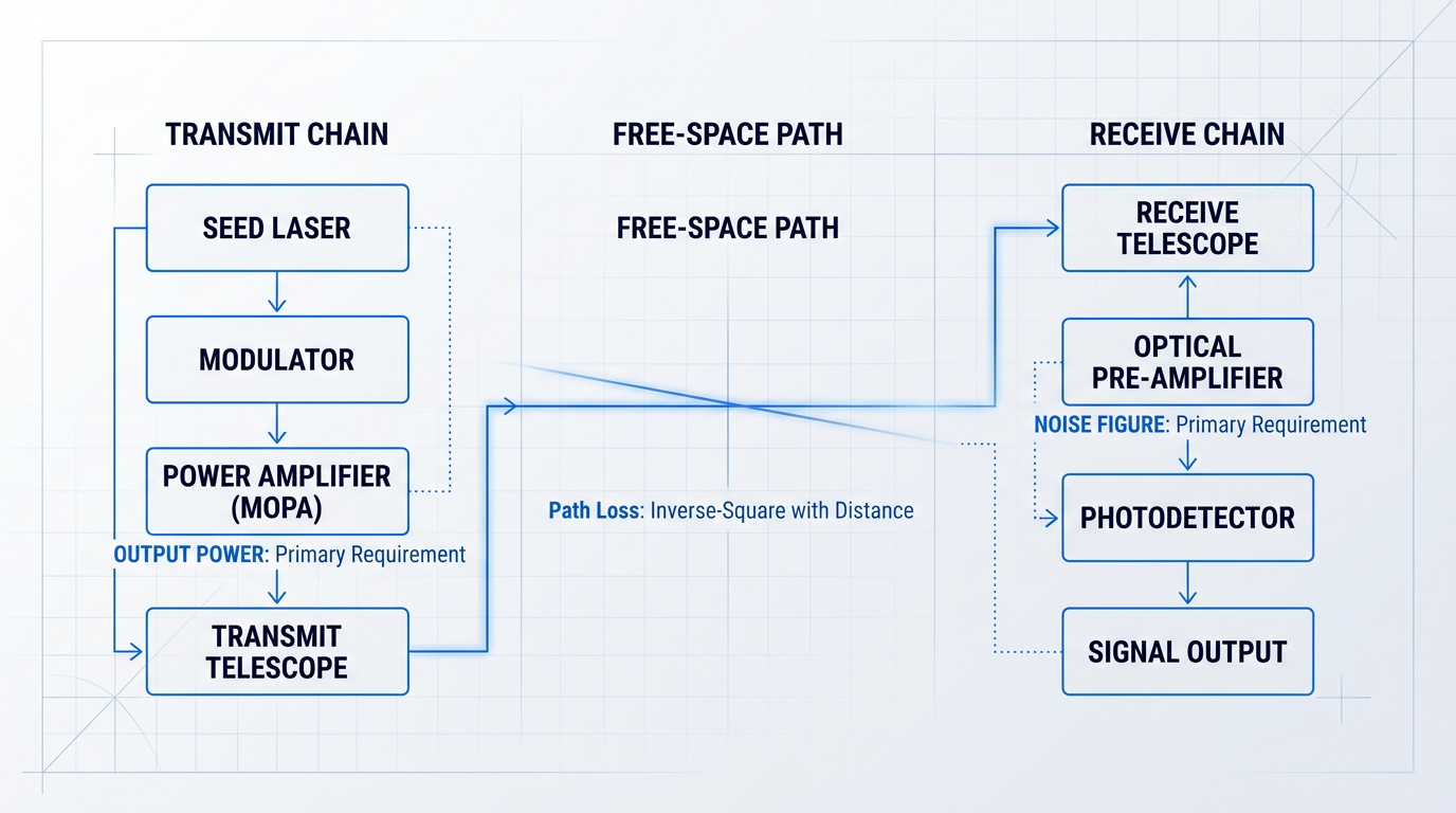
Taken together, these amplifier stages are primary inputs to the FSO link budget: the system-level accounting of all optical power gains and losses along the signal path, from transmitter to detector.
Amplifier output power sets the starting margin; gain determines how much the signal is boosted at each stage; and noise figure governs how much of that margin is consumed by the amplifier's own noise contribution — making amplifier selection a system-level decision, not a component-level one.
In fibre systems, amplifiers are spaced at regular intervals along the span — every 80 km in long-haul DWDM, for example. In FSO, there is no amplification along the free-space path itself. Every decibel of link margin must be built into the terminal amplifiers at design time, making the link budget a fixed constraint rather than something that can be patched with an extra in-line stage.
That architectural difference from fibre runs deeper than the absence of distributed amplification: fibre systems also manage chromatic dispersion in the optical domain, and their amplifiers interface with fibre connectors in a controlled guided-wave environment.
FSO propagation introduces negligible chromatic dispersion, so dispersion compensation is not a design concern — but the amplifier must instead interface with free-space optical elements such as telescopes, beam expanders, and collimators, which imposes beam quality requirements that simply have no equivalent in fibre amplifier design.
With the functional roles, link-level physics, and architectural distinctions established, the natural next question is which amplification technologies are actually used to fill each of these roles — and what their respective characteristics mean for FSO system design.
Core amplification technologies used in FSO systems
Three distinct amplification technologies are deployed in free space optical systems: the erbium-doped fibre amplifier (EDFA), the semiconductor optical amplifier (SOA), and the Er/Yb co-doped, cladding-pumped fibre laser amplifier. They are not interchangeable — each occupies a different position in the performance space, and each becomes the right tool under a different set of FSO system constraints.
EDFA is the dominant technology by a considerable margin, and this section reflects that asymmetry intentionally. SOA and fibre laser amplifiers are covered in the context of where they diverge from EDFA and where that divergence becomes an advantage — not as equal alternatives requiring equal depth.
Erbium-doped fibre amplifier (EDFA)
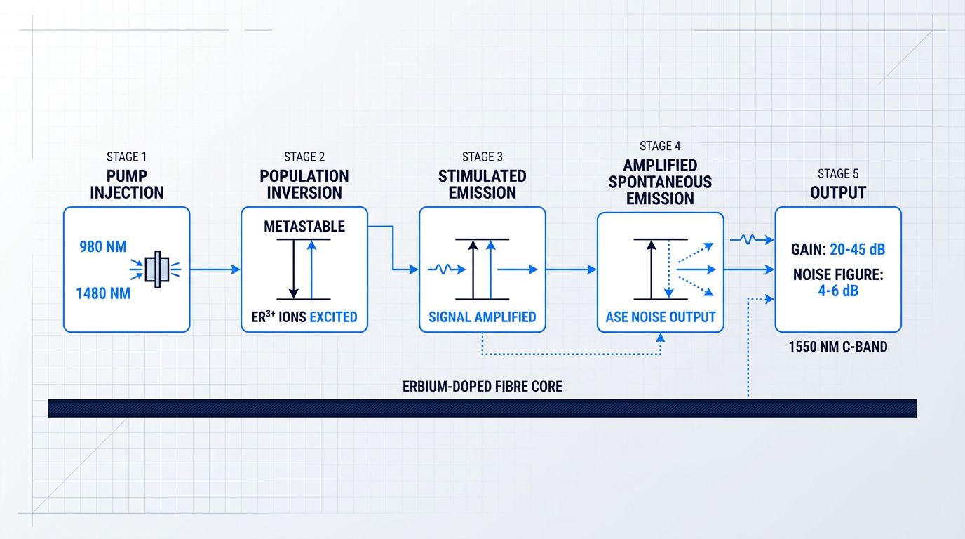
The EDFA gain medium is a length of silica optical fibre whose core is doped with trivalent erbium ions (Er³⁺). Pump light — typically at 980 nm or 1480 nm, supplied by laser diodes — is absorbed by the Er³⁺ ions, exciting them into a metastable upper energy level.
This creates population inversion: more ions occupy the excited state than the ground state, enabling incoming signal photons to trigger stimulated emission and be amplified as they propagate through the doped fibre.
Alongside stimulated emission, the excited ions also emit photons spontaneously and at random — a fraction of which are guided along the fibre core and amplified in the same way as the signal. This amplified spontaneous emission (ASE) is the fundamental and unavoidable noise mechanism in every EDFA, and it sets a lower bound on the achievable noise figure.
Quantum optics establishes that no phase-insensitive optical amplifier — regardless of the physical mechanism — can achieve a noise figure below 3 dB in the high-gain limit. Practical EDFAs approach this limit closely, with well-designed forward-pumped configurations achieving noise figures in the 4–6 dB range.
The key performance parameters that make EDFA the reference technology for FSO amplification are summarised below.
- Gain range: Typically 20–45 dB in single-stage configurations, sufficient to amplify a modulated seed signal to useful FSO transmit power levels.
- Noise figure: 4–6 dB in practical forward-pumped designs, approaching the 3 dB quantum limit — the best achievable among common FSO amplifier technologies.
- Saturated output power: High-power EDFA designs routinely achieve 20 dBm (100 mW) or more; booster configurations push further into the watt class.
- Polarisation insensitivity: As an all-fibre device, EDFA provides polarisation-independent gain — a significant advantage for FSO links where polarisation state is not controlled.
The dominance of EDFA in FSO systems is not a coincidence of history — it reflects a convergence of three mutually reinforcing advantages at 1550 nm.
First, the EDFA gain band — the C-band spanning 1530–1565 nm, with extension into the L-band to approximately 1625 nm — aligns precisely with the lowest-loss atmospheric transmission window, which was already established as the preferred FSO operating wavelength in the guide's earlier sections.
Second, 1550 nm operation carries an important eye-safety advantage: at this wavelength, light is absorbed in the cornea and lens before reaching the retina, allowing significantly higher permissible exposure levels than shorter-wavelength alternatives such as 1064 nm.
Third, the EDFA component ecosystem is extraordinarily mature, inherited directly from decades of fibre telecommunications deployment. Pump diodes, WDM couplers, Faraday isolators, and gain-flattening filters are all available as qualified, high-reliability components — a depth of supply chain that no competing FSO amplifier technology can match.
Semiconductor optical amplifier (SOA)
The SOA replaces the rare-earth-doped fibre with a semiconductor gain medium — typically an InGaAsP or similar III-V compound — fabricated as a monolithic chip.
Rather than optical pumping with a separate laser diode, the SOA is electrically pumped by injected current, which directly creates the carrier population inversion needed for optical gain. This eliminates the pump laser entirely, and the resulting chip-scale form factor is the SOA's most consequential structural difference from EDFA.
For FSO applications, the SOA's performance profile presents a clear trade-off against EDFA. Gain is lower — typically up to around 30 dB for high-performance devices, compared with 20–45 dB for EDFA — and the noise figure is higher, typically in the 6–10 dB range versus 4–6 dB for a well-designed EDFA.
The SOA also exhibits polarisation-dependent gain: because the semiconductor waveguide geometry creates different confinement factors for transverse-electric and transverse-magnetic polarisation modes, the gain is inherently polarisation-sensitive unless specifically engineered otherwise, which has implications for coherent FSO receivers.
One characteristic that distinguishes the SOA fundamentally from EDFA is its gain dynamics. The carrier lifetime in a semiconductor medium is measured in nanoseconds — orders of magnitude shorter than the millisecond-scale upper-state lifetime of Er³⁺ in silica. This means SOA gain responds to signal power changes on nanosecond timescales, creating faster saturation dynamics that must be managed carefully in high-data-rate FSO links.
The primary FSO case for the SOA is SWaP-constrained platforms: without a pump laser, the SOA module is substantially smaller, lighter, and lower in power consumption than an equivalent EDFA assembly, making it attractive for small satellites, airborne terminals, and other mass- and volume-limited applications.
Research presented at SPIE Photonics West 2025 (Space Dynamics Laboratory) demonstrated a watt-class 1550 nm SOA achieving 26.8 dBm output power with an open eye diagram using the Space Development Agency's Tranche 1 protocol — showing that SOA output power at FSO-relevant levels is no longer a purely theoretical prospect, though noise figure and gain remain below EDFA performance.
Er/Yb co-doped cladding-pumped fibre laser amplifiers
When standard EDFA output power is insufficient — for high-power ground station uplink beams or deep-space transmitter applications requiring multi-watt to tens-of-watts class output — the technology of choice shifts to Er/Yb co-doped, cladding-pumped fibre laser amplifiers.
The operating principle builds on EDFA but adds a critical architectural innovation. Ytterbium ions (Yb³⁺) are co-doped into the fibre alongside Er³⁺ and act as sensitiser ions: they have a substantially higher absorption cross-section than Er³⁺ at pump wavelengths around 975 nm, and they transfer their excitation energy efficiently to nearby Er³⁺ ions, which then provide gain in the 1.5 µm region.
This energy transfer mechanism enables cladding pumping via a double-clad fibre architecture: high-power multimode pump diodes are launched into a large inner cladding surrounding the doped core, rather than requiring single-mode pump lasers coupled directly into the core.
The consequence is the ability to inject far more pump power than a standard core-pumped EDFA can accommodate, enabling output powers that extend well into the multi-watt and even tens-of-watts range — a capability demonstrated in published research, including an 83 W single-frequency Er/Yb MOPA configuration.
This is a niche technology, not a general-purpose EDFA replacement. The Er/Yb cladding-pumped architecture introduces additional complexity — including management of Yb ASE near 1030–1080 nm and careful optimisation of doping concentrations — and the output beam quality must be managed for single-mode FSO coupling. Its relevance is specific: raw output power is the overriding requirement, and no other fibre amplifier architecture delivers it at 1550 nm.
The MOPA architecture: bringing it together
In practice, the amplifier technologies described above are almost always deployed within a Master Oscillator Power Amplifier (MOPA) architecture. A low-power seed laser — the master oscillator — generates the signal with the desired spectral and temporal characteristics, including data modulation at the target bit rate.
That modulated seed signal is then amplified by an EDFA or fibre laser amplifier stage to the required transmit power level, entirely independently of the modulation process.
This decoupling is the MOPA's core engineering advantage: modulation is performed efficiently at low power, where linearity and spectral purity are easy to maintain, while amplification is applied after modulation, where the amplifier's job is simply to boost power without distorting the signal.
The MOPA is the dominant transmitter architecture in high-performance FSO terminals precisely because it separates two problems that are difficult to solve simultaneously in a single device. It is the practical context in which both EDFA and Er/Yb fibre amplifiers operate as FSO power boosters — and it is the single-channel foundation on which more advanced multi-aperture architectures build.
With a clear picture of how each technology works and what its characteristic performance envelope looks like, the natural next question is how to choose between them for a specific FSO application — which is precisely what the following section addresses.
Custom EDFAs Built for Free-Space Optical Links
EDFA technology is the backbone of high-performance FSO transmit chains. See how our tailored EDFA designs — including the EDF-UL-10, purpose-built for free-space optical communications — translate that capability into a deployable solution.

Performance trade-offs: choosing the right FSO amplifier
The instinct is understandable: free-space path loss is enormous, so pick the amplifier with the highest output power and close the link. In practice, this single-metric approach reliably leads to poor FSO system outcomes. The free-space channel is unforgiving, but what it demands is a balanced amplifier — one optimised across beam quality, noise figure, gain dynamics, polarisation behaviour, and SWaP, not just raw wattage.
Each of those axes can independently determine whether a link closes or fails, and the right weighting depends entirely on the application. What follows is a comparative analysis of how EDFA, SOA, and fibre laser amplifiers perform across each axis — and which technology belongs in which class of FSO deployment.
Beam quality: why M² is a first-order criterion
EDFA and cladding-pumped fibre laser amplifiers both operate in single-mode fibre, which enforces near-diffraction-limited beam quality with an M² close to 1 at the output.
This matters because far-field power density scales directly with beam quality: a degraded M² spreads the transmitted beam, reducing the power density at the receiver aperture below what the raw output power figure implies.
SOA presents a more complex picture. Edge-emitting semiconductor devices produce an elliptical output beam with fast-axis divergence reaching 25–40° and slow-axis divergence around 8–10°, along with astigmatism that requires correction optics before the beam can be usefully launched into free space.
Tapered SOA architectures improve this substantially: reported slow-axis M² values of 1.1 have been demonstrated at watt-class output powers, though the fast-axis figure and the astigmatic correction burden remain design constraints.
For long-range FSO links where far-field power density is the binding constraint, beam quality is a first-order selection criterion. An amplifier that delivers 1 W with M² ≈ 1 concentrates more power on a distant aperture than one delivering 2 W with a degraded beam — and the gap widens with range.
Gain saturation and modulation format compatibility
EDFA's upper-state lifetime is of the order of 10 ms — meaning the gain reservoir responds only to changes averaged over thousands or millions of pulse slots, not to individual bits.
In practice, EDFA gain is effectively frozen during the timescale of high-speed modulation. This makes it inherently compatible with on-off keying (OOK) and pulse-position modulation (PPM) formats used in deep-space FSO: every pulse slot sees the same gain, with no inter-symbol gain variation regardless of the data pattern.
SOA's gain dynamics operate on a nanosecond timescale — fast enough to respond to individual pulses in a high-speed pulsed format.
This creates patterning effects: when a sequence of '1' bits depletes the gain, the following '1' bits are amplified less than those after a run of '0' bits, producing inter-symbol interference from gain depletion — a significant impairment in OOK and PPM formats that is absent from EDFA-amplified links.
EDFA's ~10 ms upper-state lifetime means its gain is blind to individual pulse slots, making it inherently pattern-independent. SOA's nanosecond-scale dynamics create gain depletion between consecutive pulses — a patterning penalty that directly degrades OOK and PPM link performance.
Noise figure and receiver sensitivity
In an optically pre-amplified FSO receiver, the pre-amplifier noise figure directly sets the receiver sensitivity floor — it is the first element in the receive chain and its excess noise cannot be recovered downstream.
| Parameter | EDFA | SOA (fibre-coupled) | Er/Yb Fibre Laser Amplifier |
|---|---|---|---|
| Noise figure | 4–6 dB (approaching 3 dB quantum limit) | 6–10 dB (typically higher due to coupling loss and polarisation dependence) | Determined by Er/Yb fibre design; high-power configurations optimised for output, not pre-amplifier NF |
| Typical output power | Up to ~27 dBm (500 mW) standard; multi-watt with cladding pump | Up to ~30 dBm (1 W) demonstrated; >30 dBm in research | Multi-watt to tens of watts; 4.5 W (DSOC), 10–40 W demonstrated for space uplinks |
| Beam quality (M²) | ~1 (single-mode fibre output) | 1.1 slow-axis demonstrated (tapered); fast-axis correction required | ~1 (single-mode fibre output) |
| Gain dynamics | ~10 ms upper-state lifetime; pattern-independent | Nanosecond-scale; patterning effects in pulsed formats | ~10 ms; similar to EDFA |
| Polarisation sensitivity | Near-insensitive (isotropic erbium gain medium) | Polarisation-dependent (TE/TM differential gain) | Near-insensitive (fibre-based); PM variants available |
| SWaP | Moderate-high (pump laser, WDM coupler, thermal management) | Low (electrically pumped directly; no pump laser subsystem) | High (cladding pump diodes, thermal management for high power) |
Comparison of key performance parameters across EDFA, SOA, and Er/Yb fibre laser amplifiers for FSO applications, using figures from RP Photonics, SPIE proceedings, and NASA programme sources.
The noise figure gap between EDFA and SOA is not a minor footnote. A 3–4 dB difference in pre-amplifier noise figure translates directly to a 3–4 dB reduction in receiver sensitivity — which in a link budget means either a proportionally shorter maximum range or a requirement for more transmit power to compensate.
Er/Yb cladding-pumped fibre laser amplifiers are principally deployed as high-power transmit boosters rather than pre-amplifiers; their noise figure in that configuration is a secondary concern relative to output power and efficiency.
Polarisation sensitivity in coherent FSO receivers
EDFA's erbium gain medium in standard single-mode fibre is isotropic, producing polarisation-insensitive amplification — or very close to it — without special design measures.
SOA gain is intrinsically polarisation-dependent: the TE and TM modes of the semiconductor waveguide experience different gain levels, a consequence of the asymmetric waveguide geometry.
In a coherent FSO receiver, the polarisation state of the received beam varies continuously due to atmospheric propagation and platform motion, so a polarisation-sensitive pre-amplifier produces gain variations correlated with that drift.
This directly degrades coherent detection performance — a structural disadvantage that SOA cannot easily resolve without specialised polarisation-diversity designs, whereas EDFA's insensitivity is an inherent property of the gain medium.
SWaP: the trade-off that defines platform suitability
EDFA delivers its performance advantages at the cost of size, weight, and power. The dominant contributor is the pump laser subsystem — the 980 nm or 1480 nm pump diode, WDM coupler, and associated thermal management — which adds mass and volume that a compact space terminal may not accommodate.
SOA is electrically pumped directly, eliminating the pump laser entirely. The result is a substantially more compact package with lower power draw — a meaningful advantage when the platform imposes strict SWaP constraints.
The SWaP trade-off maps clearly onto application context: high-performance satellite platforms and long-range terrestrial FSO links favour EDFA, while mass-constrained CubeSat platforms — where performance penalties can be managed through larger receive apertures, shorter link distances, or reduced data rates — make SOA a viable candidate.
Application mapping: which technology for which FSO link
With the comparative analysis complete, the application-specific guidance follows directly from the performance axes above.
- EDFA for high-performance FSO: Satellite-to-ground links, optical inter-satellite links (OISLs), and long-range terrestrial FSO — wherever link margin, receiver sensitivity, and beam quality are primary drivers — EDFA is the default.
- SOA for SWaP-constrained platforms: CubeSat FSO terminals where mass and power are the binding constraints. Watt-class SOA demonstrations at 1550 nm, including Space Development Agency protocol evaluations, confirm SOA is maturing beyond laboratory use.
- Er/Yb fibre laser amplifiers for highest-power transmitters: Ground-to-GEO uplinks and deep-space optical communications transmitters requiring multi-watt to tens-of-watts output with maintained single-mode beam quality.
NASA's O2O ground uplink transmitter for the Artemis II mission illustrates the EDFA tier: four commercial off-the-shelf EDFA-based high-power optical amplifiers each delivering up to 10 W, for a combined 40 W aggregate output, using PPM-32 modulation at 1550 nm — a system that depended on EDFA's combination of high output power, low noise figure, and pattern-independent gain.
The DSOC flight laser transceiver on NASA's Psyche mission illustrates the Er/Yb tier: a cladding-pumped, polarisation-maintaining Er/Yb fibre amplifier delivering up to 4.5 W at 1550 nm in a MOPA configuration, supporting PPM modulation formats for deep-space optical communications at distances exceeding 2 AU.
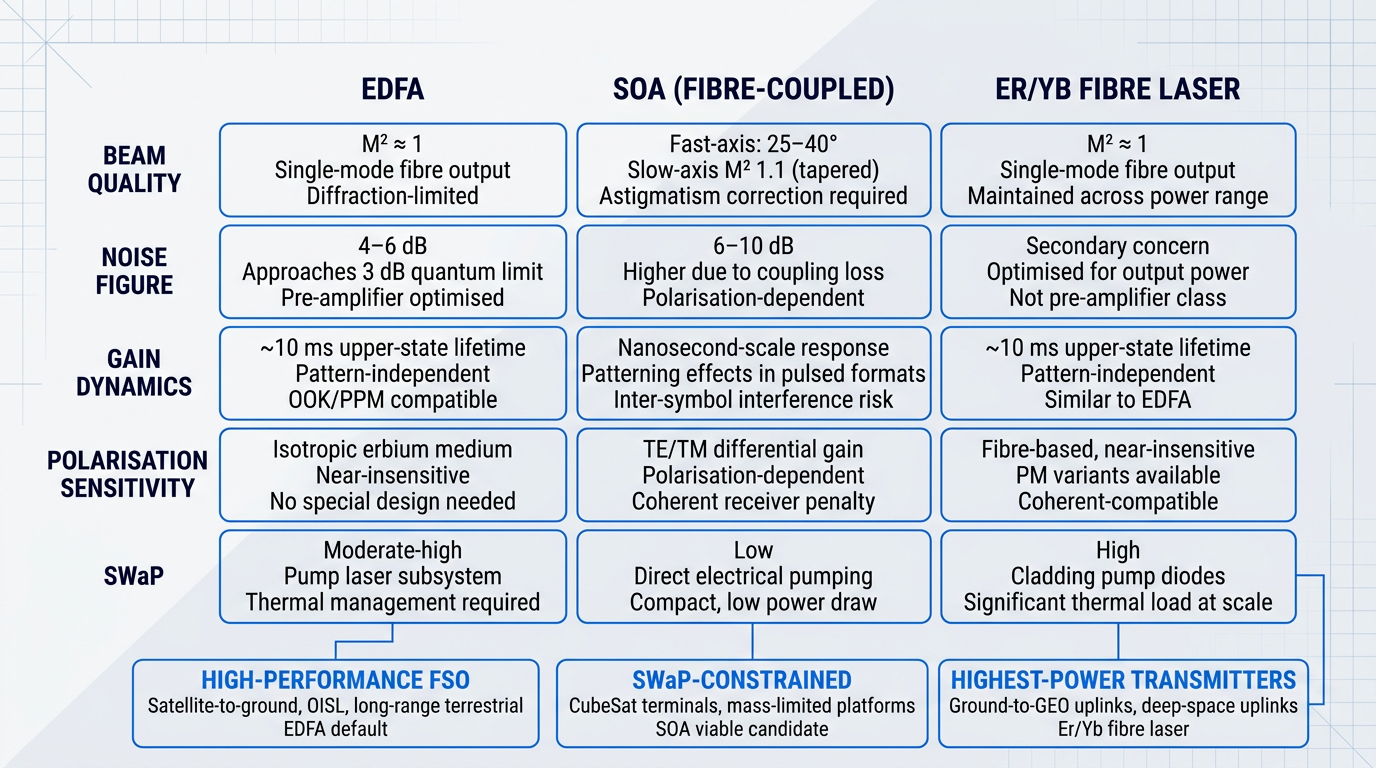
The SWaP and output power dimensions introduced here take on additional complexity in space and airborne deployments, where radiation tolerance, thermal management under vacuum conditions, and ruggedised packaging impose further constraints on amplifier design — topics the next section addresses in depth.
FSO Amplifier Operational Demands: Power, SWaP, Radiation
Selecting an FSO amplifier technology is only half the engineering problem. The other half is ensuring that the chosen amplifier can actually survive and perform in the environment where it will be deployed — and those environments impose constraints that have no equivalent in the fibre-optic world. A rack-mounted EDFA in a climate-controlled data centre faces none of the pressures that shape FSO amplifier design: multi-watt output demands driven by free-space path loss, mass and power budgets tight enough to dictate pump diode architecture, ionising radiation that progressively degrades the gain medium, and mechanical and thermal stresses that would destroy commercial-grade packaging within months.
Output Power Requirements Driven by Free-Space Path Loss
Unlike guided-wave systems, where optical loss is measured in dB per kilometre of fibre and in-line amplifiers compensate incrementally, free-space path loss scales with the square of link distance and cannot be mitigated by any intervening medium.
For satellite-to-ground and optical inter-satellite links (OISLs), this translates directly into transmitter power requirements that are orders of magnitude beyond what conventional fibre telecom amplifiers deliver: where in-line EDFAs typically operate in the milliwatt-to-low-watt range, FSO transmitter amplifiers must reach multi-watt to tens-of-watts class output to close the link budget at satellite distances.
Recent SPIE proceedings document this concretely: a 5 W average output power fibre laser transmitter has been designed for GEO deployment, while the NASA Deep Space Optical Communications flight terminal operated a laser transmitter assembly capable of up to 4 W average power at 1550 nm — with high-burst-rate modes requiring on-bit powers exceeding 10 W to 20 W for low-rate command links.
For LEO satellite-to-satellite crosslinks, published link budget analyses indicate that boosting the transmitted laser diode signal to around 1 W and amplifying the received signal by 40 dB is required to achieve optical power budgets of approximately 70 dB needed to compensate for diffraction-limited beam divergence over distances exceeding 5,000 km.
SWaP Constraints in Space and Airborne FSO Missions
For satellite-borne and airborne FSO terminals, size, weight, and power (SWaP) are co-equal design constraints — not secondary considerations to be optimised once optical performance is achieved.
NASA's SmallSat State of the Art report documents the challenge directly: on SmallSat platforms, limited volume and tight packaging are often a major challenge in the design of low-SWaP laser communication terminals, compounded by thermal management difficulties — it is difficult to radiate enough heat with limited radiator surface area — and power constraints driven by limited solar array area.
Real-world CubeSat terminal designs illustrate the envelope: DLR's CubeISL terminal, which incorporates a receive optical path and fibre amplifier for 100 Mbps crosslinks at up to 1,000 km and 1 Gbps downlinks, targets a mass below 1 kg, a volume of 1U, and an operating power of approximately 30 W — a complete optical communications terminal including amplification.
These constraints shape amplifier architecture directly. Wall-plug efficiency becomes a primary design metric rather than an afterthought, because every watt of electrical power consumed by the amplifier competes with pointing, processing, and communications electronics on a fixed power budget.
Eliminating thermoelectric coolers from pump diode assemblies — accepting uncooled pump diode operation — is a common architectural response, trading some efficiency and output power stability for the mass and power savings that make the terminal viable on a constrained platform.
Radiation Tolerance and Space Qualification
Of all the environmental demands on space-deployed FSO amplifiers, ionising radiation is the most technically differentiated — and the most consequential for long-duration missions.
Ionising radiation from cosmic rays, trapped protons in the Van Allen belts, and solar particle events induces radiation-induced attenuation (RIA) in erbium-doped fibres through a specific physical mechanism: colour centre formation, where defect sites created in the glass matrix absorb both signal and pump photons, progressively degrading gain and output power.
Critically, RIA is not a binary failure event — it is a gradual performance degradation that must be modelled over the full mission lifetime, with end-of-life performance predicted from accumulated total ionising dose (TID) and dose rate.
NASA GSFC radiation effects research has established that aluminium content in the fibre core is a dominant variable in RIA susceptibility — in some cases, varying Al₂O₃ content can change radiation-induced darkening by an order of magnitude, as demonstrated by comparing Yb-doped fibres with 1.0 mol% versus 4.2 mol% Al₂O₃ exposed to the same total dose: the higher-aluminium fibre exhibited 12 dB/m of induced attenuation versus 1 dB/m for the lower-aluminium candidate.
This means fibre dopant composition is an engineering lever, not a fixed material property: designing for radiation tolerance requires selecting or specifying fibre with optimised aluminium content, rather than accepting whatever dopant profile a commercial fibre manufacturer has chosen for telecom applications.
Pump wavelength sensitivity adds a further design dimension. NASA GSFC sensitivity data on Er-doped fibres shows that radiation-induced attenuation at 980 nm pumping is approximately three times greater than at 1300 nm and roughly five times greater than at 1550 nm — confirming that shorter-wavelength pump photons experience substantially greater absorption from radiation-induced defects, a factor that favours 1480 nm pumping in radiation-sensitive space applications.
For GEO missions accumulating higher total dose over longer lifetimes, and for LEO missions passing through the South Atlantic Anomaly, design margins must account for end-of-life degraded performance. Typical GSFC mission radiation environments range from 15 Krad over 10 years for LEO Earth observation missions to 100 Krad over 5 years for higher-altitude science missions.
Genuine space qualification of fibre amplifier components is a rigorous, multi-step engineering process — emphatically not the same as selecting a commercial off-the-shelf component and labelling it space-grade. The NASA NEPP program is explicit on this point: COTS photonic components are not intended for use in the space environment and require thorough testing to ensure sufficient radiation hardness, in the same way COTS silicon microcircuits require evaluation before flight insertion.
A qualification campaign for a space-deployed fibre amplifier component involves four distinct testing regimes, each targeting a specific failure mode.
- Radiation Testing: Gamma and proton irradiation to mission-relevant TID levels, with dose rate extrapolation modelling to predict on-orbit performance at realistic space dose rates.
- Thermal Vacuum Testing: Performance characterisation across the full operational temperature range in vacuum, capturing outgassing, thermal cycling shrinkage, and material CTE mismatch effects.
- Vibration and Shock Testing: Random vibration and mechanical shock testing to protoflight levels — typically 14 to 20 grms per NASA GSFC NEPP profiles — to demonstrate survival of launch loads without optical performance degradation.
- End-of-Life Performance Prediction: Modelling of degraded amplifier output power and gain after the full mission radiation dose, using kinetic models extrapolated from accelerated dose-rate test data.
The NASA GSFC NEPP program specifies a minimum of 30 thermal cycles for high-risk assemblies and 100 or more cycles for optoelectronic components intended for longer-duration missions — requirements derived from observed failure modes including fibre coating delamination, cable component shrinkage, and connector end-face degradation under repeated thermal stress.
The NASA GSFC approach, developed across missions including GLAS, MLA, LOLA, and LRO, requires lot-specific qualification — the flight parts come from the same manufacturing lot as the tested samples — combined with construction analysis, materials screening, and in-situ optical monitoring during environmental testing.
Selecting a component with flight heritage from a different mission and claiming qualification by similarity is not adequate when the radiation environment, temperature range, or mission duration differs materially from the heritage case.
NASA GSFC research shows that aluminium co-doping level, not erbium concentration, is the primary determinant of radiation-induced attenuation in Er-doped and Yb-doped fibre amplifiers. Two fibres with nearly identical rare-earth content but different Al₂O₃ levels exhibited a 12× difference in RIA at the same total dose — making fibre composition specification the most powerful radiation-hardening lever available to the amplifier designer.
Ruggedised Packaging for Terrestrial and Airborne Deployments
Outside the space environment, FSO amplifiers deployed on airborne platforms and in outdoor terrestrial enclosures face a different but equally demanding set of environmental constraints — ones that commercial-grade fibre telecom amplifiers, designed for climate-controlled facilities, are not engineered to meet.
Thermal management is particularly challenging: pump diode thermal management in field-deployed or airborne enclosures must function without the benefit of active air conditioning, across wide ambient temperature swings, and with limited surface area for heat rejection.
The gap between component temperature grades captures the engineering stakes precisely: a commercial-grade component is rated for 0°C to 70°C, an industrial-grade component for −40°C to +85°C, and a military-grade component for −55°C to +125°C — and for airborne or ground-mobile FSO deployments, industrial or military ratings are the baseline requirement, not an upgrade.
NASA NEPP qualification guidelines specify that thermal testing for optoelectronic assemblies should add 10°C to each extreme beyond the box-level environment, with 100 or more thermal cycles required for components intended for longer missions — a standard derived from observed failure modes in space and aerospace photonic assemblies.
Vibration and shock tolerance is a parallel requirement for UAV-mounted and ground-mobile FSO amplifiers: airborne platforms subject amplifiers to continuous broadband vibration and transient mechanical shock that demand ruggedised component mounting and packaging — not the soft-mounted, connector-terminated assemblies typical of rack equipment.
Hermetic sealing of optical components and fibre splices is the standard protective approach for field-deployed and airborne enclosures, excluding humidity, dust, and condensation that would degrade splice performance and corrode pump diode facets over operational lifetimes.
The operational demands covered in this section — output power, SWaP, radiation tolerance, and ruggedised packaging — govern what an FSO amplifier must survive and function within. The next category of design inputs acts on the link itself: atmospheric impairments including turbulence, scintillation, and background noise that shape the link margin requirements the amplifier must ultimately satisfy.
Atmospheric Impairments and Amplifier Design Implications
The atmosphere is the one design variable in an FSO link that cannot be engineered away. Platform, packaging, and amplifier technology are all within the designer's control; the propagation medium is not. What can be controlled is how the system is specified to survive it. Each atmospheric impairment discussed below is a characterisable input with an established statistical model and a direct line to an amplifier design requirement — output power margin, noise figure specification, or receive-chain architecture.
Fog and Aerosol Attenuation
Fog is the dominant worst-case impairment for terrestrial FSO links. NASA technical analyses and experimental propagation studies confirm that fog attenuation can reach hundreds of dB/km under dense conditions — values that dwarf the molecular scattering baseline of clear air by orders of magnitude. The SPIE link margin guidelines for 1550 nm links show required margins ranging from around 10 dB/km for light fog up to 30–120 dB/km for heavy-to-severe fog, with measured peak attenuation values exceeding 300 dB/km at very low visibilities.
The amplifier design implication is direct: the transmit-side power booster cannot be sized for clear-weather path loss alone. Link availability requirements drive the margin above the clear-weather baseline, and that margin is what sets the amplifier's output power specification. For a terrestrial link targeting high availability in a fog-prone region, the MOPA booster stage must deliver enough output power to keep the received signal above threshold during the statistically defined worst-case attenuation event, not just the median.
Scintillation and Intensity Fading
Scintillation is a distinct impairment from fog and one that is present even under clear-sky conditions. It arises from random refractive index variations driven by temperature gradients and turbulent mixing, which cause the atmosphere to act like a continuously shifting array of weak lenses — producing rapid, random fluctuations in received signal intensity on millisecond timescales. NASA propagation analyses show that scintillation-induced temporal fades typically last on the order of a few milliseconds, with fades of 10 dB or larger observed more than 10 percent of the time under worst-case turbulence conditions.
Fade statistics are characterised using the Rytov variance and, in the weak-turbulence regime, a log-normal intensity distribution — well-established models that allow the fade depth at a required availability percentile to be computed deterministically. A NASA analysis using the Yura and McKinley worst-case approach found that a link margin of approximately 20 dB is required for the system to operate properly 99.9 percent of the time under worst-case scintillation, though aperture averaging at the receiver can substantially reduce this requirement for ground-based terminals.
The amplifier implication is that output power margin must account for scintillation-induced fades on top of mean path loss — and this requirement exists independently of fog. A system that sizes its booster amplifier for clear-weather loss plus fog margin but ignores scintillation statistics will be underspecified for availability at the required percentile.
Turbulence and Receiver Coupling Efficiency
On the receive side, atmospheric turbulence creates the most architecturally significant amplifier design constraint. Turbulence degrades wavefront coherence across the receiver aperture, distorting the spatial phase of the incoming beam. For a fibre-coupled receiver — where the downlink signal must be focused into a single-mode fibre (SMF) at the input of an EDFA pre-amplifier — this wavefront distortion directly reduces coupling efficiency. The average coupling efficiency for a passive system without adaptive optics is fundamentally limited by the ratio of aperture diameter to atmospheric coherence length (D/r₀); as D/r₀ increases, coupling efficiency degrades substantially.
The consequence for the pre-amplifier is that the signal entering the EDFA is weaker than the aperture-collected power would suggest, while the amplifier's ASE noise floor remains fixed. This effectively degrades the signal-to-noise ratio at the amplifier input, tightening the noise figure requirement on the pre-amplification stage. It is the atmospheric coupling penalty — not just the free-space path loss — that drives the pre-amplifier noise figure specification in turbulence-affected receive chains.
Adaptive optics (AO) placed upstream of the SMF coupler is the established architectural response. By measuring wavefront distortion with a wavefront sensor and applying a conjugate correction via a deformable mirror, AO restores the beam to near-diffraction-limited quality before coupling into the fibre. JPL's ground terminal development for NASA's LCRD mission demonstrates the requirement in practice: the Integrated Optical System uses a woofer-tweeter deformable mirror design with a Shack-Hartmann wavefront sensor operating at frame rates on the order of 10 kHz, targeting coupling efficiencies above 55 percent under nominal seeing conditions.
AO adds SWaP, latency, and optical complexity to the receive chain — a 20 percent power tap to the wavefront sensor alone represents a meaningful signal budget cost. But it is the enabling technology for high-efficiency SMF coupling under turbulence, and without it, the pre-amplifier noise figure requirement becomes impractical to satisfy through amplifier design alone.
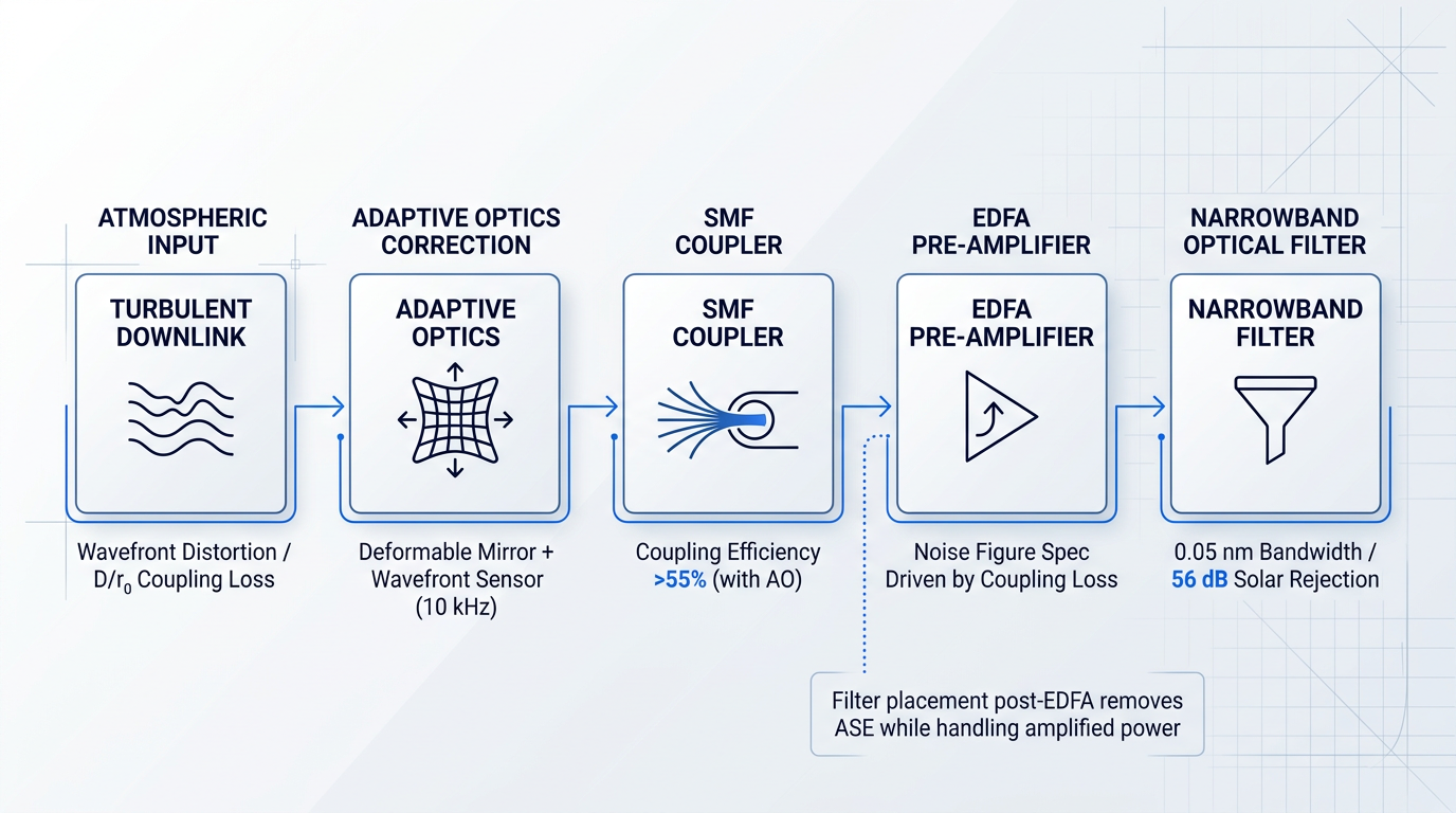
The chain from turbulence to amplifier performance is worth stating explicitly: wavefront distortion reduces SMF coupling efficiency, which weakens the signal at the pre-amplifier input, which tightens the noise figure requirement — a cascade that originates in the atmosphere and resolves in the amplifier specification.
Atmospheric turbulence reduces SMF coupling efficiency at the pre-amplifier input, weakening the received signal while the amplifier's ASE noise floor stays constant. The result is an effective noise figure penalty that cannot be corrected by amplifier design alone — only adaptive optics upstream of the fibre coupler restores the coupling efficiency that the pre-amplifier specification assumes.
Uplink vs. Downlink Turbulence Asymmetry
Turbulence does not affect uplink and downlink equally, and the asymmetry has direct implications for where amplification margin is most critical. On the uplink, the transmitted beam encounters the turbulent boundary layer near the ground at the very start of its propagation path. At this point the beam is narrow, and the dominant effect is beam wander — random displacement of the beam centroid at the receiver. NASA propagation analyses confirm that beam wander and angle-of-arrival fluctuations are the principal degradation mechanisms for earth-to-space uplinks, with uplink losses from these effects substantially exceeding downlink losses for the same link geometry.
On the downlink, the beam traverses the turbulent boundary layer at the end of its propagation, after expanding to a large aperture. The dominant effects shift to scintillation and spatial coherence degradation across the receiver aperture — the conditions that reduce SMF coupling efficiency. The uplink transmitter must therefore provide margin for beam wander-induced pointing loss, while the downlink receiver pre-amplifier is challenged by the wavefront distortion and coupling efficiency penalty that AO is designed to mitigate.
Solar Background Noise and Optical Filtering
During daytime operation, solar radiance within the receiver's field of view creates a background photon flux that is indistinguishable from signal photons within the optical passband. This raises the effective noise floor at the detector and, in optically pre-amplified receivers, interacts with the amplifier's ASE. The JPL DESCANSO monograph on deep-space optical communications identifies diffuse sky radiance, scattered sunlight, and planetary backgrounds as the primary noise sources for ground-based daytime receivers — all of which scale directly with the receiver's optical bandwidth and field of view.
The engineering response is narrowband optical filtering to reject out-of-band solar radiance while passing the signal wavelength. Single optical filters with bandwidths as narrow as 0.05 nm are achievable, and Faraday anomalous dispersion optical filters (FADOFs) have demonstrated solar background noise rejection of 56 dB in NASA research. The placement of the filter relative to the pre-amplifier is a system architecture decision: filtering before the pre-amplifier reduces the ASE bandwidth and solar background entering the amplifier; filtering after the pre-amplifier removes broadband ASE but must handle the higher optical power at the amplifier output.
JPL research on adaptive optics for background noise mitigation shows that AO can reduce detected sky background by one to two orders of magnitude under poor seeing conditions by concentrating the signal into a smaller field of view — demonstrating that AO and narrowband filtering are complementary, not alternative, strategies for managing solar background noise in the receive chain.
The 1550 nm operating wavelength sits in a favourable atmospheric transmission window — a spectral region of low molecular absorption and scattering relative to shorter candidate wavelengths. This atmospheric advantage reinforces the technology-wavelength pairing established in earlier sections: the EDFA gain band and the atmospheric transmission window align, providing a doubly motivated rationale for the 1550 nm standard in FSO systems.
The atmospheric impairments covered here — particularly turbulence-induced coupling efficiency loss and solar background noise — are precisely the phenomena that make pre-amplifier noise figure a critical specification rather than a secondary one. The next section addresses noise figure and ASE in depth, examining the physics of why these atmospheric inputs translate into such demanding amplifier performance requirements.
Noise Figure and ASE: Signal Quality in FSO Amplifiers
Output power is the metric engineers reach for first — and in an FSO link, with its enormous free-space path loss, that instinct is understandable. But output power only determines how much signal leaves the transmitter; noise figure determines whether the receiver can extract useful information from what arrives, already weakened by path loss and atmospheric effects.
The root cause of noise in EDFA-based systems is amplified spontaneous emission (ASE): a consequence of the same population inversion that produces gain. Excited erbium ions decay spontaneously — a probabilistic quantum process that cannot be suppressed — and a fraction of that spontaneous emission couples into the fibre waveguide and is then amplified along the gain medium alongside the signal. ASE is not a design flaw; it is a fundamental physical consequence of operating any phase-insensitive optical amplifier, and it sets the floor on achievable noise performance.
Noise figure is defined as the ratio of input signal-to-noise ratio to output SNR, expressed in decibels — a measure of how much the amplifier degrades the signal's SNR. Quantum mechanics imposes a hard lower bound of 3 dB on any ideal, high-gain, phase-insensitive amplifier: even a theoretically perfect amplifier must add at least one noise photon per mode. This quantum noise limit is not a specification target; it is a physical constraint that no amplifier design can circumvent. In practice, real EDFAs achieve noise figures of approximately 4–6 dB, with the gap above 3 dB arising from incomplete population inversion, internal component losses, and other imperfections.
In an optically pre-amplified FSO receiver, the pre-amplifier's noise figure is the dominant determinant of receiver sensitivity. A 1 dB improvement in pre-amplifier noise figure translates almost directly into 1 dB of additional link margin — the difference between closing the link and not.
This is where the FSO context diverges sharply from long-haul fibre systems. In a fibre network, ASE accumulates across many cascaded in-line amplifiers over many spans, and system designers manage the noise budget through careful span-by-span accounting — no single amplifier's noise figure dominates the result. In an FSO link, there is no distributed amplification along the propagation path; the pre-amplifier at the receiver is typically the first amplification stage after an extremely high free-space path loss, and in deep-space links the incoming signal can approach single-photon-per-bit levels.
In that architecture, the pre-amplifier's noise figure is not one contributor among many — it is the system-level sensitivity-determining parameter. Placing a low-noise optical pre-amplifier immediately before the photodetector lifts the weak incoming signal above the detector's thermal noise floor, so the receiver's effective sensitivity is set by the amplifier's noise figure rather than the detector's characteristics. Crucially, gain and noise figure are not independently optimisable within a single amplifier stage: the noise figure of the first stage dominates regardless of how much gain follows it.
Pump direction and inter-stage ASE filtering
The direction of the pump laser relative to the signal is one of the most direct design levers for controlling noise figure. Forward pumping — where the pump co-propagates with the signal — creates strong population inversion near the input end of the erbium fibre, precisely where the signal is weakest and where ASE generation is most damaging to SNR. Backward pumping concentrates inversion near the output end, which favours maximum output power but produces a worse noise figure because the signal traverses a less-inverted input region first.
- Forward pump: Preferred for pre-amplifiers: strong inversion at the input minimises ASE where SNR is most vulnerable, achieving near-quantum-limited noise figure.
- Backward pump: Preferred for power booster amplifiers: strong inversion at the output maximises saturated output power; the higher noise figure is acceptable with a strong input signal.
- Bidirectional pump: Balances noise figure and output power; forward-pump dominance shifts performance toward the pre-amplifier regime when noise figure is the priority.
In multi-stage amplifier designs — common in high-gain or high-power FSO terminals — out-of-band ASE generated by the first stage can saturate the second stage and raise the noise floor across the system. Narrow-band optical filters, such as fibre Bragg gratings or thin-film bandpass filters, placed between stages suppress ASE outside the signal band before it propagates further. This is standard practice in multi-stage FSO amplifier design; the trade-off is that each filter adds insertion loss that must be accounted for in the overall gain budget.
A related consideration is gain saturation: when input power is high enough to partially deplete the population inversion, noise figure increases and ASE behaviour shifts relative to the unsaturated regime. Power booster amplifiers routinely operate in saturation to extract maximum output power, and this is an accepted trade-off — the input signal is already strong, so noise figure is not the critical parameter. For a pre-amplifier, saturation must be avoided, because degrading noise figure at precisely the stage where receiver sensitivity is set undermines the entire architecture.
With the single-amplifier performance envelope now fully characterised — gain, output power, noise figure, beam quality, and environmental robustness — the natural next question is what happens when even a perfectly optimised amplifier cannot deliver the output power a demanding FSO link requires. That is the territory of scaling architectures, and it is where the next section picks up.
See the EDFA Built for Optical Ground-Station Uplinks
The EDF-UL-10 is a 10 W EDFA built for free-space optical communications, serving both the uplink and beacon roles at an optical ground station in a single module.

Coherent Beam Combining: Scaling FSO Transmit Power
There is a hard physical ceiling on how much power you can extract from a single fibre amplifier channel, and no amount of additional pump power will break through it. For FSO systems targeting high-power ground-to-satellite uplinks, that ceiling is not an inconvenience — it is the central design constraint. Coherent beam combining (CBC) exists precisely to circumvent it.
The Nonlinear Power Ceiling: Why SBS Limits Single Channels
As average and peak power in a fibre amplifier channel increase, stimulated Brillouin scattering (SBS) becomes the dominant limiting mechanism: acoustic phonons in the fibre generate a counter-propagating wave that back-reflects signal energy, effectively capping usable output.
The SBS threshold scales with fibre core area and inversely with fibre length, meaning that simply scaling up pump power or fibre length does not raise the ceiling proportionally — it often lowers it.
Stimulated Brillouin scattering imposes a fundamental power limit on any single fibre amplifier channel. CBC bypasses this limit not by raising the threshold, but by parallelising channels — each operates safely below SBS onset, and their outputs combine to reach aggregate powers no single channel could deliver.
CBC bypasses this constraint by distributing the amplification task across multiple parallel channels, each running below the SBS threshold, and then combining their outputs coherently so the aggregate power reaches levels that would be physically inaccessible from any individual channel.
Combining Geometries: Tiled and Filled Aperture
Two distinct geometries are used to combine the outputs of a CBC array: tiled aperture and filled aperture.
- Tiled aperture: Each channel illuminates a separate sub-aperture; beams interfere constructively in the far field, producing a combined intensity pattern without a physical combining element.
- Filled aperture: Beams are combined in the near field (pupil plane) using a beam-combining element before the aperture, producing a single spatially coherent output beam.
In both geometries, phase coherence is the non-negotiable prerequisite: if the channels are not phase-locked, their outputs add incoherently, and the combined beam loses its near-diffraction-limited quality — the on-axis intensity advantage that makes CBC worthwhile collapses.
The MOPA Array Architecture
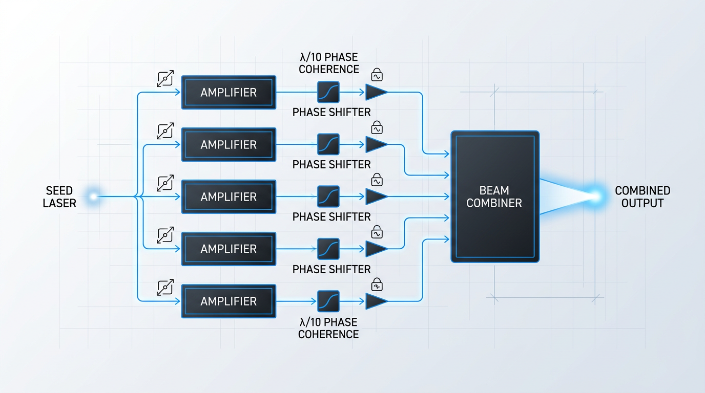
CBC in FSO is implemented as a MOPA array: a single master oscillator seeds multiple parallel amplifier channels, each independently amplifying the common seed signal before combination.
The shared seed source is what makes coherent combination possible — it gives all channels a common phase reference from the outset, so the phase differences that accumulate through independent amplification are small and correctable rather than random and uncorrelated.
Before the outputs reach the combining element, an active phase control loop measures and corrects the relative phases in real time, using electro-optic or piezoelectric phase shifters to lock the channels together.
Phase Coherence: The Central Engineering Challenge
Maintaining mutual phase coherence across all channels to within a small fraction of a wavelength — typically λ/10 or better — is the defining engineering challenge of a CBC system.
Thermal gradients, acoustic vibrations, and mechanical perturbations in the fibre continuously disturb the relative phases of independent amplifier channels, requiring active correction at bandwidths that can range from tens of hertz to several kilohertz depending on the operating environment.
Phase sensing is typically implemented via a stochastic parallel gradient descent (SPGD) algorithm or a dedicated phase measurement channel; the correction actuators — electro-optic modulators or piezoelectric fibre stretchers — must respond fast enough to track the perturbation rate.
The bandwidth and accuracy of this correction loop directly determine combining efficiency: a loop that cannot track fast enough leaves residual phase error that degrades the constructive interference and reduces on-axis intensity in the combined beam.
Gain Uniformity and Polarisation Control
Phase coherence is necessary but not sufficient: gain uniformity across channels is equally critical, because the combined beam's on-axis intensity is maximised only when all channels contribute equal power.
Achieving this requires matched pump power delivery, consistent fibre lengths and splice losses across the array, and — in practice — active power balancing, since passive matching alone rarely sustains the required uniformity across temperature and ageing.
All channels must also deliver matched polarisation states at the combining element: any polarisation mismatch reduces interference contrast and degrades combining efficiency, making polarisation-maintaining (PM) fibre amplifiers a non-negotiable requirement throughout the MOPA array.
PM amplifiers carry additional SWaP and cost overhead relative to non-PM designs — a real constraint in space-qualified systems — but there is no viable alternative in a CBC architecture where polarisation mismatch directly translates to lost combining efficiency.
Ground Station Uplinks: The Primary FSO Application
The FSO application domain where CBC is most consequential today is the high-power ground-to-satellite uplink — particularly feeder links to GEO satellites, where the free-space path loss over tens of thousands of kilometres demands transmit powers that no single fibre amplifier channel can supply.
The EPOS (European high-Power space Optical communication System) programme illustrates the scale of ambition: it targets very high optical transmit powers at the ground terminal, with space-borne amplifier requirements also reaching levels that push the boundaries of current single-channel technology — power levels that are only practically achievable through CBC architectures.
These programmes make clear that CBC is not a laboratory technique awaiting maturation: it is the architectural path that the FSO community has identified as the route to closing high-capacity GEO feeder links at operationally relevant data rates.
Atmospheric Pre-Compensation via CBC Phase Control
Beyond raw power scaling, CBC arrays offer a second capability that is conceptually elegant: the same phase control infrastructure that locks channels together for coherent combination can be repurposed to implement wavefront pre-distortion on the transmitted beam.
For ground-to-space uplinks, where the beam must traverse the full depth of the turbulent atmosphere before reaching the satellite, pre-distorting the wavefront to be the conjugate of the expected atmospheric phase aberration allows the beam to arrive at the satellite with significantly reduced turbulence-induced spreading.
This requires real-time knowledge of the atmospheric phase distortion — typically derived from a guide star return or an uplink beacon signal — and represents a convergence of CBC engineering with adaptive optics disciplines.
It is an emerging capability rather than a universally deployed feature, but its significance lies in the fact that it comes at no additional hardware cost: the phase actuators already present for coherent combination are the same actuators used for wavefront shaping.
Coherent beam combining is, ultimately, the most demanding expression of FSO amplifier engineering: it requires simultaneous mastery of output power, beam quality, polarisation control, phase coherence, gain uniformity, and environmental robustness — every performance dimension this guide has examined, brought to bear at once. The Conclusion draws together all of these decision axes into a practical framework for engineers evaluating amplification architectures for their specific FSO link requirements.
Conclusion
Selecting the right FSO amplifier: a multi-dimensional engineering decision
Selecting a free space optical amplifier is not an exercise in maximising a single parameter — output power, noise figure, beam quality, SWaP, radiation tolerance, and atmospheric margin all pull on the design simultaneously.
The free-space environment imposes requirements with no equivalent in guided-wave systems, and treating FSO amplifier selection as a fibre-optic problem with a different propagation distance leads to poor outcomes.
From here, the practical work is link budget analysis, space qualification scoping, and — for high-power applications — coherent beam combining architectures where amplifier-level decisions directly constrain system capability.
Frequently Asked Questions: Free Space Optical Amplifiers
Answers to the most common technical questions about optical amplifiers in FSO communication systems.
An optical amplifier boosts the optical signal directly, without converting it to an electrical signal first. In an FSO system, it serves three distinct roles depending on placement: a transmit-side power booster that maximises output power before the telescope, a receive-side pre-amplifier that recovers weak incoming signals with minimal added noise, and an in-line relay amplifier that regenerates signals in multi-hop or relay-satellite architectures. Direct optical amplification is preferred over optical-electrical-optical (OEO) conversion because it preserves signal quality, introduces no latency from electronic processing, and operates transparently across different modulation formats — the same amplifier works whether the link uses intensity modulation, phase-shift keying, or pulse-position modulation.
A modulated laser signal is transmitted through open air or space, propagates across the free-space channel, and is collected by a receiving telescope focused onto a photodetector. Optical amplifiers compensate for the free-space path loss and atmospheric attenuation that would otherwise make the signal too weak to detect reliably. Unlike fibre links, where the signal is guided and loss is low and predictable, FSO links face variable atmospheric attenuation from fog, turbulence, and scintillation, plus geometric path loss that grows with the square of distance. This is why high-output-power amplifiers on the transmit side and low-noise pre-amplifiers on the receive side are critical enabling components — without them, the link budget cannot be closed over distances of practical interest.
An erbium-doped fibre amplifier works by pumping an erbium-doped optical fibre with a 980 nm or 1480 nm pump laser, creating a population inversion in the erbium ions. When 1550 nm signal photons pass through the gain medium, they trigger stimulated emission, producing additional photons at the same wavelength and phase — amplifying the signal without any electrical conversion. The primary noise output of an EDFA is amplified spontaneous emission (ASE): spontaneously emitted photons that are themselves amplified along the fibre. The noise figure of a well-designed EDFA approaches 3 dB (the quantum limit for a high-gain amplifier), with practical forward-pumped devices typically achieving 4–6 dB. This makes EDFA the lowest-noise amplification technology available for 1550 nm FSO systems, and the reason it dominates both transmit-side and receive-side amplifier designs in high-performance FSO terminals.
The standard approach is the master oscillator power amplifier (MOPA) architecture: a low-power modulated seed laser is amplified by an EDFA or fibre laser amplifier to the required transmit power before the telescope. On the receive side, a low-noise pre-amplifier placed before the photodetector boosts the weak incoming signal, improving receiver sensitivity. FSO amplification is inherently two-sided. The transmit side is about maximising output power to close the link budget against free-space path loss and atmospheric attenuation; the receive side is about minimising noise figure to recover the weakest detectable signal. For very high-power applications — ground station uplinks, deep-space transmitters — coherent beam combining of multiple parallel MOPA channels is used to scale total output power beyond what a single amplifier channel can deliver, while preserving beam quality and phase coherence.
Three reinforcing factors make 1550 nm dominant. First, it coincides with the EDFA gain band (C-band), making mature and high-performance amplification directly available. Second, it sits in a favourable atmospheric transmission window with relatively low molecular absorption. Third, it benefits from higher permissible exposure limits under eye-safety standards than shorter wavelengths such as 850 nm or 1064 nm, which matters for ground-based terminals and technician safety. Beyond these primary reasons, the 1550 nm band carries decades of fibre telecom component development — pump lasers, isolators, couplers, and gain fibres — all of which transfer directly into FSO amplifier design. This ecosystem maturity translates to lower component cost, higher demonstrated reliability, and a far wider range of design options than any competing wavelength can offer.
A power booster operates on the transmit side, typically in gain saturation, to maximise output power — the goal is raw optical power to overcome free-space path loss over the link distance. A pre-amplifier operates on the receive side at very low input signal levels, and is optimised for minimum noise figure to maximise receiver sensitivity rather than output power. The engineering implications of this distinction are significant. Because a booster operates in saturation, its noise figure is less critical than its output power and wall-plug efficiency. A pre-amplifier's noise figure directly sets the receiver sensitivity floor, so forward-pumped EDFA designs — which achieve the lowest noise figures — are strongly preferred. The two amplifiers are optimised for fundamentally different operating regimes even when the underlying gain technology, such as EDFA, is identical in both.
Space qualification of FSO amplifiers involves a rigorous programme of radiation testing (gamma and proton irradiation to characterise radiation-induced attenuation in the gain fibre), thermal vacuum cycling, vibration and shock testing, and end-of-life performance prediction. It is a systematic engineering and test discipline, not simply selecting a commercial-grade component and relabelling it as space-grade. The specific radiation challenge is that ionising radiation induces attenuation in erbium-doped fibres — a phenomenon known as radiation-induced attenuation (RIA) — and the severity depends strongly on fibre dopant composition. Aluminium co-doping is a key variable: higher aluminium content increases radiation sensitivity. Radiation-induced attenuation is also significantly higher at shorter wavelengths, which means 980 nm pump light is more susceptible than the 1550 nm signal wavelength. Genuine space qualification requires characterising these effects at mission-representative dose rates and total doses, and demonstrating adequate end-of-life performance margins before flight.