


Introduction
If you're here, you already know what optical amplifiers do — this isn't the place to start from first principles.
Most resources on the subject are organised around technology: here's an EDFA, here's a Raman amplifier, here are some things each one is used for. That framing puts the technology first and treats the application as an afterthought.
The territory this guide covers runs from long-haul fibre networks and dense wavelength-division multiplexed systems through submarine cables and data centre interconnects, and out into optical sensing, precision navigation, biomedical imaging, and all-optical signal processing.
The goal is to leave you with a clear sense of the engineering rationale behind each technology choice — not just a map of what goes where, but an understanding of why.
TL;DR
There is no universally best optical amplifier — only the one that fits the demands of a specific application. Across every domain covered here, from transoceanic cables to surgical imaging systems, the technology choice follows from the application's requirements. Understanding that logic is what separates engineers who select amplifiers from those who merely specify them.
This article covers:

Long-haul fibre-optic communications and why EDFA dominates
WDM and DWDM gain management across channels
Submarine cable systems and metro/data centre networks
LIDAR, distributed sensing, and fibre Bragg gratings
Fibre optic gyroscopes and precision navigation
Biomedical imaging and all-optical signal processing
What Are the Applications of Optical Amplifiers?
Optical amplifiers boost signals directly in the optical domain, with no electrical conversion — making them inherently protocol-agnostic and capable of amplifying dozens of wavelength channels simultaneously. That transparency is what makes them system components whose value is defined entirely by the application context: the same physics that underpins a transoceanic repeater also enables a precision gyroscope or a surgical imaging source. The applications of optical amplifiers span long-haul telecommunications, metro and data centre networks, LIDAR, fibre optic sensing, biomedical imaging, and all-optical signal processing — and each domain places a different set of demands on the amplifier chosen to serve it.
Three Amplifier Families: A Deployment Map
Rather than a taxonomy of operating principles, the three principal amplifier families are best understood by where they are actually deployed and why each is chosen for those contexts.
- EDFA: The workhorse of commercial telecommunications infrastructure, dominant in long-haul fibre and WDM/DWDM systems where C-band and L-band gain aligns with silica fibre's lowest-attenuation window.
- Raman: Uses the transmission fibre itself as the gain medium, delivering distributed amplification valued for noise improvement, reach extension, and bandwidth expansion — typically complementing EDFA rather than replacing it.
- SOA: Compact, electrically pumped, and integrable with photonic circuits; covers wavelengths outside the EDFA window, including O-band, and suits metro, data centre, sensing, and biomedical applications.
Choosing between these families is never purely a matter of performance specifications — it is a question of which family's deployment profile fits the application's constraints on wavelength range, integration density, noise budget, and physical environment.
Five Performance Parameters as Application Levers
Five parameters recur throughout every domain covered in this guide, but none of them is a universal metric to maximise — each is a lever whose optimal setting is dictated by the specific application.
- Noise figure: Governs OSNR accumulation across cascaded spans; sets detection sensitivity floor in sensing systems. Lower is better — but the target differs sharply by application.
- Gain bandwidth: Determines how many WDM channels can be amplified simultaneously; wider bandwidth enables greater spectral capacity in dense wavelength-division systems.
- Output power: Sets maximum launch power into the next fibre span; governs reach in unrepeatered links and peak power in pulsed sensing and LIDAR architectures.
- Polarisation-mode dependence: Critical in coherent transmission and precision sensing — particularly fibre optic gyroscopes — where polarisation state directly affects signal fidelity.
- Gain saturation: Limits output under high input power; relevant in multi-channel WDM loading and in pulsed MOPA architectures where saturation shapes pulse energy.
The noise figure specification that matters for a submarine repeater is categorically different from the one that matters for an OCT imaging source — and the gain saturation behaviour that is a problem in a WDM booster may be a useful nonlinearity in an SOA-based signal processor.
Amplifier selection is always downstream of application requirements. The amplifier that dominates long-haul transmission may be entirely wrong for a fibre optic gyroscope or a data centre switch — and vice versa. The right starting point is always the application, not the amplifier.
It is also worth flagging from the outset that laboratory demonstrations and deployed systems operate under very different constraints: environmental qualification, pump laser lifetime, component availability, and integration complexity are engineering realities the research literature rarely surfaces but practitioners always face.
With that framework in place — three amplifier families, five performance levers, and an application-first selection principle — the guide moves through each deployment domain in turn, examining what each application actually demands and which amplifier configuration best delivers it.
Long-Haul Fibre-Optic Communications: Why EDFA Dominates
Imagine a signal leaving a transmitter in London, bound for a data centre thousands of kilometres away. By the time it reaches the first amplifier site — typically 45 to 100 km down the fibre — it has lost a significant fraction of its power to attenuation. An amplifier restores it. Then the process repeats, span after span, through dozens of amplifier stages. The problem is not restoring power: it is that each amplifier adds noise, and that noise accumulates with every stage.
The governing metric is optical signal-to-noise ratio (OSNR). In a cascade of amplifiers, OSNR degrades cumulatively — and the system must be engineered so that OSNR at the far end of the link, after all those amplifier stages, still sits above the threshold required for error-free detection.
This is the engineering pressure that drives amplifier selection in long-haul systems. Every design decision — amplifier type, noise figure, gain flatness, pumping configuration — traces back to this single constraint: maintaining adequate OSNR across all channels, over the full link length.
Why the C-Band and EDFA Are Inseparable
The reason EDFA dominates long-haul transmission is not that it is generically superior to other amplifier types — it is that its gain window aligns precisely with the lowest-attenuation transmission window of silica fibre.
ITU-T defines the C-band as 1530–1565 nm and the L-band as 1565–1625 nm. This is exactly where silica fibre has its lowest loss, and it is exactly where erbium-doped fibre provides gain. The C-band definition itself originated from the EDFA gain window — the two are historically and physically coupled.
A second property makes EDFA uniquely suited to WDM systems: the long upper-state lifetime of erbium ions, measured at approximately 10 ms in silica glass. This value — four orders of magnitude longer than the carrier lifetime in semiconductor optical amplifiers — is the mechanism that enables simultaneous amplification of many WDM channels without inter-channel crosstalk.
Because the gain medium cannot respond fast enough to fluctuations in individual channel power, all channels are amplified essentially independently. Semiconductor optical amplifiers, by contrast, have fast carrier dynamics and suffer from cross-gain modulation in WDM applications — a fundamental reason they are not used in long-haul WDM systems.
Noise Figure: The Parameter That Determines Reach
In a long-haul cascade, noise figure (NF) is the primary EDFA performance parameter. The ideal EDFA has a 3 dB noise figure; practical, high-quality devices achieve 4–6 dB. Because OSNR degradation accumulates with each amplifier in the chain, even a 1 dB improvement in NF translates directly into either a longer achievable transmission distance or a higher channel count at a given OSNR target.
For a cascade of equal amplifiers, OSNR degrades cumulatively with each stage. A lower noise figure directly extends how far a signal can travel before accumulated noise makes error-free detection impossible — making NF the single most consequential amplifier parameter in long-haul system design.
Pumping configuration is one lever for managing NF. Forward pumping (pump and signal co-propagating) minimises noise figure because the signal is amplified early in the gain fibre, before significant ASE accumulates — making it the preferred configuration for preamplifier stages. Backward pumping (counter-propagating) maximises output power at some cost to NF, making it better suited to booster stages. Bidirectional pumping combines both, achieving low NF alongside high output power in demanding inline configurations.
Amplifier Roles in a Long-Haul Span
Long-haul systems deploy EDFAs in three distinct functional roles, each with different performance priorities.
- Booster amplifier: Placed after the transmitter to maximise launch power into the first span. Output power is the critical parameter; NF is secondary.
- In-line amplifier: Compensates for span loss at each intermediate node. Must balance both NF and output power across the full link.
- Preamplifier: Placed before the receiver to maximise sensitivity before detection. Low NF is the defining requirement here.
In practice, the boundaries between these roles are not always rigid — system designers often use two-stage amplifier architectures, with a low-noise first stage and a high-power second stage, to serve inline functions while also accommodating mid-stage components such as dispersion-compensating elements.
Gain Flatness: A System-Level Discipline
An untreated EDFA does not amplify all wavelengths equally. The erbium gain spectrum has a characteristic shape — a narrow peak near 1530 nm and a broader, lower region around 1550 nm — meaning different WDM channels receive different amounts of gain.
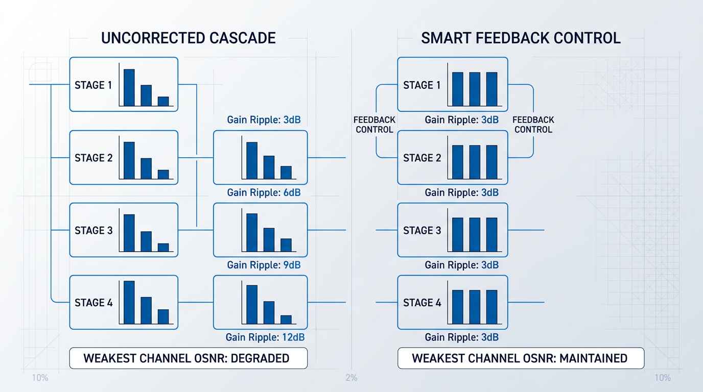
In a single amplifier, this variation is manageable. Across a cascade of dozens of amplifiers, it compounds: channels near gain peaks accumulate far more amplification than channels in gain troughs. One source quantifies this effect at approximately 10 dB of channel power divergence after 20 amplifier spans — enough to severely degrade OSNR on the weakest channels while risking nonlinear penalties on the strongest.
Gain-flattening filters (GFFs) address this by imposing a loss profile that is the inverse of the EDFA gain curve, equalising channel powers at each amplifier stage. The two dominant implementation technologies are thin-film dielectric filters and fibre Bragg gratings (FBGs), each capable of achieving gain variation below 1 dB across the C-band in commercial quantities.
Static GFFs are designed for a fixed set of operating conditions. When channel loading changes — as channels are added or dropped, or as amplifiers age — the gain profile shifts, and static filters can no longer fully compensate. Dynamic gain equalisation (DGE) addresses this by applying an electronically adjustable inverse filter, enabling the amplifier to maintain flatness across varying traffic conditions and extending the achievable span count before electrical regeneration is required.
Raman Amplification: A Complement, Not a Replacement
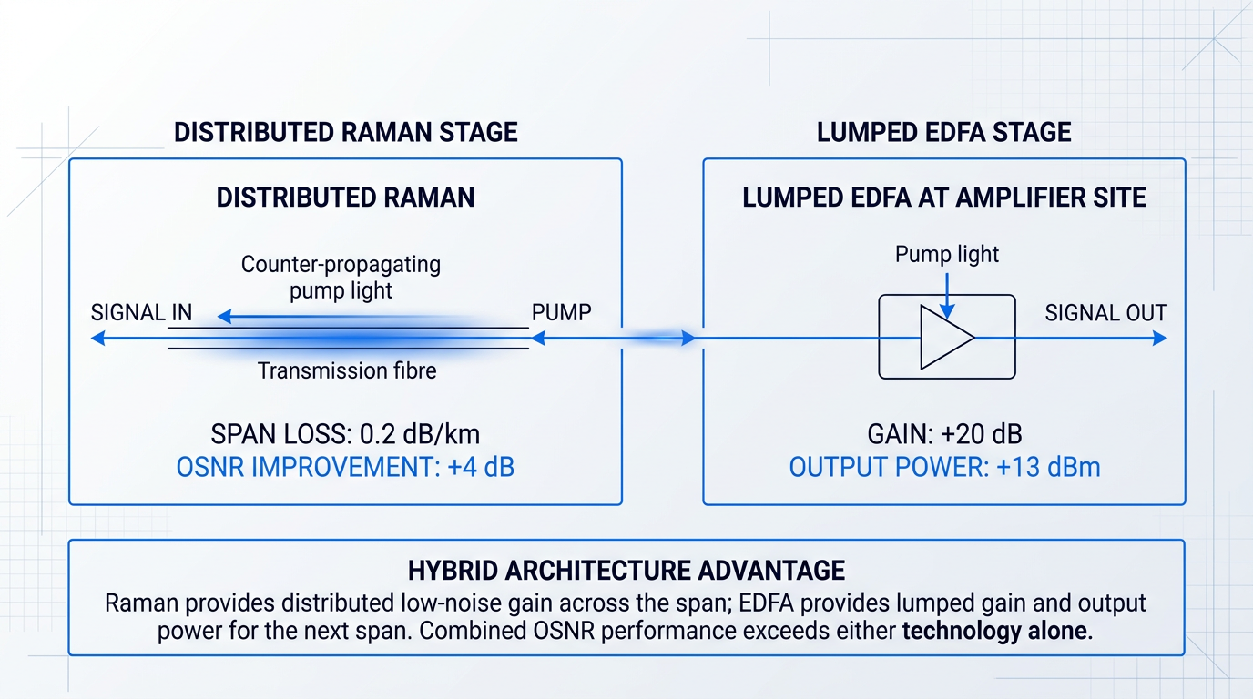
In the most demanding long-haul scenarios, distributed Raman amplification is deployed alongside EDFA — not as an alternative to it. Raman uses the transmission fibre itself as the gain medium: pump light is launched (typically counter-propagating) into the fibre, providing gain distributed across the span rather than concentrated at a lumped amplifier point.
Because the signal is amplified before it has attenuated to its minimum level within the span, the effective noise contribution of the span is reduced. Measured results confirm that a hybrid Raman/EDFA configuration can deliver more than 4 dB of improvement in the noise floor compared with a conventional EDFA alone over the same span — a gain that translates directly into extended reach or increased channel count.
The standard deployment model positions a distributed Raman stage as a low-noise preamplifier ahead of the lumped EDFA at each amplifier site. The Raman stage provides distributed gain and improves OSNR; the EDFA provides the lumped gain and output power needed to drive the next span. Each technology addresses a different part of the amplification problem — which is why the hybrid architecture has become the configuration of choice for ultra-long-haul and high-capacity routes.
From Design to Deployment: The Implementation Layer
Moving from a validated amplifier design to a deployed long-haul system introduces constraints that the research literature often underweights. Pump laser reliability is the most consequential: pump failure is the dominant failure mode in EDFA systems, and the industry's response — dual-pump architectures, rigorous burn-in qualification, and MTTF targets exceeding two million hours — reflects how seriously this risk is managed in deployed infrastructure.
Fibre type also interacts with amplifier performance in ways that matter at the system level. Different fibre nonlinearity and dispersion profiles alter what the amplifier chain must compensate for, influencing both the choice of amplifier configuration and the placement of dispersion-compensating elements within the mid-stage.
Finally, forward error correction (FEC) sets the minimum acceptable OSNR threshold at the receiver — meaning amplifier performance targets cannot be set in isolation from the FEC scheme the system uses. The practical OSNR budget is a system-level calculation, not a single-amplifier specification.
The gain flatness and channel management principles introduced here become significantly more complex when the number of WDM channels scales into the hundreds across C and L bands — the territory of dense WDM systems, where gain tilt accumulation, transient suppression, and dynamic equalisation all demand closer attention.
WDM and DWDM Systems: Managing Gain Across Many Channels
Compensating for span loss is one problem. Doing it uniformly across 80 or more simultaneous wavelength channels, through a cascade of amplifiers spanning thousands of kilometres, while the channel loading shifts dynamically — that is an entirely different engineering discipline.
In a DWDM system, every channel occupies a distinct wavelength slot and travels through the same amplifier simultaneously.
The amplifier has no awareness of which channel carries which traffic — it amplifies the entire optical spectrum at once, applying its gain profile indiscriminately across all wavelengths present.
Any non-uniformity in the EDFA's gain spectrum translates directly into unequal channel powers at the amplifier output.
In a single-span link, a few dB of gain variation across the C-band may be manageable. In a cascaded multi-span system, it is not: the gain imbalance compounds with every amplifier stage, progressively widening the power spread between the strongest and weakest channels.
By the end of a long cascade, the weakest channels may have accumulated insufficient optical signal-to-noise ratio (OSNR) to be decoded error-free, while the strongest channels may be driving nonlinear impairments in the fibre.
It is always the weakest channel that sets the system's performance ceiling — which is why gain flatness is not a component specification to be maximised in isolation, but a system-level constraint that emerges from cascaded deployment.
An untreated EDFA gain spectrum varies by several dB across the C-band. In a multi-span cascade, that variation compounds at every amplifier stage — making spectrally flat amplification an engineering discipline in its own right, not a refinement applied after the fact.
Gain-Flattening Filters: Static and Dynamic Solutions
The first-order engineering response to EDFA gain non-uniformity is the gain-flattening filter (GFF) — a passive spectral shaping element inserted at the amplifier output to attenuate the high-gain wavelengths and pass the low-gain ones.
Two technologies dominate static GFF implementations: thin-film interference filters and fibre Bragg gratings (FBGs), both fabricated to closely approximate the inverse of the EDFA gain profile across the C-band.
- Thin-film filters: Deposited multilayer coatings shaped to the inverse EDFA gain profile; compact and cost-effective for fixed channel plans.
- Fibre Bragg gratings: Periodic refractive index variations written into the fibre core; offer high spectral resolution and low insertion loss.
Static GFFs are effective when the channel plan is fixed and the amplifier operates at a stable gain setpoint — conditions that describe many point-to-point long-haul links.
Their fundamental limitation is that they are optimised for a single operating point: a specific gain level and a specific channel loading condition.
When channels are added or dropped, when pump power drifts due to component ageing, or when the channel plan is reconfigured, a static GFF cannot adapt.
It continues to apply the attenuation profile it was designed for — which may no longer match the amplifier's actual gain shape, reintroducing the channel power divergence it was installed to prevent.
This is where dynamic gain equalisation becomes necessary. In reconfigurable networks with variable channel loading, the gain profile changes continuously, and a programmable spectral attenuator is required.
Dynamic gain-flattening filters (DGFFs) are real-time programmable spectral attenuators that can reshape their attenuation profile in response to measured channel powers, keeping the output spectrum flat as network conditions evolve.
Several mature technology platforms are deployed in practice, each suited to different operating environments.
Acousto-optic devices offer fast electrical control; MEMS (micro-electromechanical systems) arrays provide fine-grained per-wavelength attenuation with low power consumption.
Liquid-crystal elements combine high spectral resolution with compact form factors, while planar lightwave circuit (PLC) approaches enable monolithic integration with other waveguide components.
The choice of DGFF platform is driven by the speed of response the network requires and the integration environment of the amplifier module — not by any single platform being universally superior.
Gain Tilt and Transient Suppression in Live Networks
Gain tilt is a wavelength-dependent slope in the amplifier's gain spectrum that arises when the total input signal power distribution shifts, causing the amplifier to operate at a different inversion level than its design point.
The more operationally urgent challenge is gain transients. When channels are suddenly added or dropped in a DWDM network — as occurs routinely in ROADM-based architectures — the surviving channels experience an abrupt redistribution of the amplifier's total output power.
These power surges and drops can be rapid enough to cause bit errors in the affected channels before any slow control loop can respond.
Critically, the disturbance does not stay local: each successive amplifier in the cascade responds to the changed input power level, potentially amplifying the disturbance rather than absorbing it.
The engineering response is the smart amplifier: an EDFA with an embedded feedback control loop that monitors output channel powers continuously and adjusts pump laser drive current or variable optical attenuator (VOA) settings in real time to suppress transients before they propagate.
Transient suppression is not a theoretical refinement — it is a live network operational requirement in any DWDM deployment where channels are added or dropped dynamically, which today describes virtually every carrier-grade long-haul network.
Raman Amplification for Bandwidth and Tilt Control
Distributed Raman amplification complements EDFA in DWDM systems in two ways that are particularly valuable at scale: it extends the usable gain bandwidth beyond what a single-pump EDFA can cover, and it provides a mechanism for tilt pre-compensation before signals enter the lumped EDFA stage.
By deploying multiple Raman pump wavelengths simultaneously, engineers can shape the Raman gain spectrum across a broad spectral range, selectively boosting the wavelength bands where EDFA gain is weakest.
Because Raman gain is distributed along the transmission fibre rather than concentrated at a discrete amplifier site, the signal accumulates gain before its power has fallen to the noise floor — improving OSNR across all channels simultaneously.
C+L Band Splitting for High Channel Count Systems
For systems carrying more than approximately 40 channels, the C-band alone (roughly 1530–1565 nm) cannot accommodate all channels at the spacing required without unacceptable spectral congestion.
The solution is C+L band split amplification: the WDM signal is divided by a band-splitting coupler into C-band and L-band (approximately 1565–1625 nm) components, each amplified by a dedicated EDFA stage optimised for its respective wavelength range, then recombined for onward transmission.
This approach effectively doubles the available spectral capacity, but it introduces its own gain ripple control challenges: the two EDFA stages have different gain spectra and different saturation behaviours.
Maintaining flat, matched output power across the combined C+L band requires careful equalisation in both amplifier paths — the same gain flatness discipline applied at a larger spectral scale.
Distributed Raman pumping plays a supporting role here too, providing smooth gain across the combined C+L window and helping to bridge the spectral gap between the two EDFA stages where gain coverage would otherwise be uneven.
What unites all of these techniques — static GFFs, DGFFs, smart amplifier feedback, Raman tilt compensation, and C+L band splitting — is that none can be designed in isolation from the full system context: the channel plan, the cascade length, and the traffic dynamics all determine which combination of tools is required.
DWDM systems demand spectral engineering at every level of the amplifier chain. Submarine cable systems impose a different and in some ways more unforgiving constraint set — where the challenge shifts from spectral management to the impossibility of accessing any amplifier once it has been laid on the ocean floor.
Submarine Cable Systems: Reliability and Remote Amplification
Every design decision in a submarine cable system flows from a single, non-negotiable fact: once the cable is on the seabed, you cannot reach it for 25 years without a cable ship repair operation that costs tens of millions of dollars and weeks of vessel time.
This is categorically different from terrestrial long-haul deployment, where a failed component can be swapped in hours. The 25-year design lifetime is not a conservative engineering preference — it is a hard economic constraint that propagates into every layer of the system, from housing materials and sealing technology down to the operating point of individual pump laser diodes.
Submarine repeaters space amplifiers at roughly 40–80 km intervals along cables that run at depths of thousands of metres, with optical amplification at each repeater site compensating for the span loss accumulated between stations.
The dominant failure risk in an EDFA is the pump laser diode, and submarine repeater design addresses this directly through redundant pump configurations: two 980 nm pump LDs are provided per repeater, with their outputs combined via an optical coupler and injected into the erbium-doped fibre in both transmission directions, so that the system maintains full transmission path characteristics even if one pump fails entirely.
Critically, each pump is operated in a constant-output control mode well below its maximum rated power — a deliberate derating strategy that trades some output efficiency for a dramatic extension of pump longevity, a trade-off that only makes engineering sense when field replacement is impossible.
The reliability record this approach achieves is extraordinary: NEC's technical publications report that across more than 3,000 sets of submarine repeater equipment delivered to the market, not a single unit has failed.
The performance envelope that submarine EDFAs must meet is not arbitrary — each specification is a direct consequence of the system architecture. NEC's deployed submarine repeaters achieve output power exceeding +15–16 dBm, a noise figure below 4.5–4.7 dB, and flat gain characteristics across 36–40 nm of bandwidth, with the bandwidth target realised through optimised erbium-doped fibre lengths and individual per-repeater gain-flattening filters.
The output power target follows from span loss and channel count; the noise figure target follows from the accumulation of ASE noise across hundreds of cascaded amplifiers over transoceanic distances; and the gain flatness target follows from the need to maintain channel balance through a cascade where even small per-repeater tilt compounds into severe spectral imbalance at the far end.
Power delivery to those repeaters adds another hard constraint. Submarine repeaters carry no local power source — electrical energy is fed from shore via the cable's copper conductor as a constant DC current at voltages up to 20 kV, with all repeaters connected electrically in series along the cable.
This creates a fixed power budget for the entire repeater chain: the total power available from the shore-based power feed equipment (PFE) must be shared across every amplifier in the cable, which historically limited submarine cables to a relatively small number of fibre pairs and drove system designers toward maximising capacity per fibre rather than simply adding more fibres.
Unrepeatered Systems: Eliminating Active Electronics from the Cable
The logical endpoint of the reliability argument is to ask: what if there were no active electronics in the water at all?
A remotely optically pumped amplifier (ROPA) answers that question directly. A ROPA consists of a passive segment of erbium-doped fibre embedded in the submarine cable — no pump lasers, no electronics, no power-consuming components of any kind — pumped instead by 1480 nm light launched from the terminal equipment on shore and carried to the mid-span location via the transmission fibre itself.
The ROPA is typically placed 80–130 km from the receiver terminal, where the 1480 nm pump energy — itself boosted en route by counter-propagating Raman amplification — retains sufficient power (above ~10 mW) to invert the erbium ions and produce usable gain.
Because the submerged segment is entirely passive, ROPA architectures are inherently more reliable than conventional repeaters and extend repeaterless reach to 350 km and beyond — enabling cable routes where the economics or logistics of conventional repeater spacing would be impractical.
Distributed Raman amplification provides the complementary mechanism. In this approach, high-power pump light at approximately 1455 nm is launched from the terminal into the transmission fibre itself, which acts as the distributed gain medium via the Raman nonlinear effect — providing 8–10 dB of additional OSNR improvement per stage without any submerged active component.
Cascaded Raman architectures use multiple pump wavelengths to shift pump energy progressively toward the signal band, enabling the 1480 nm ROPA pump to reach mid-span distances that would otherwise be unachievable with a single pump stage.
Combining high-power terminal EDFAs, ROPAs, and co- and counter-propagating distributed Raman amplification at both ends of a link has pushed unrepeatered transmission distances to approximately 450 km with full WDM channel loading, and laboratory demonstrations using ultra-low-loss large-effective-area fibre have extended record distances well beyond 600 km — all without a single active electronic component anywhere in the submerged cable.
By combining ROPAs and distributed Raman amplification, engineers can achieve optical amplification across 450 km of submarine cable — and beyond in record demonstrations — with no active electronics, no pump lasers, and no powered equipment anywhere on the seabed. This is the practical culmination of the reliability-first design philosophy that defines submarine optical engineering.
From the extreme inaccessibility of transoceanic repeater chains to the fully passive elegance of ROPA-plus-Raman unrepeatered links, submarine systems represent the most demanding deployment environment for optical amplifier applications — one where the engineering constraints, not the technology itself, dictate the architecture.
The next domain shifts the challenge entirely: metro networks and data centre interconnects operate at short spans with equipment that can be accessed and reconfigured at any time, making integration density, cost efficiency, and network agility the governing pressures rather than inaccessibility and lifetime reliability.
Metro Networks and Data Centre Interconnects
Metro networks and data centre interconnects are not simply long-haul systems with shorter fibre runs. They impose a qualitatively different set of engineering demands: more nodes, more frequent channel changes, tighter cost budgets, and an integration density that long-haul designs were never optimised for.
Where long-haul amplifier design centres on OSNR accumulation across thousands of kilometres, metro and data centre amplifier design centres on agility, cost-per-node, and the ability to respond dynamically to a network that is constantly being reconfigured.
Metro ROADM Networks: Agility Over Distance
The structural driver of amplifier demand in metro networks is insertion loss at each ROADM node, not fibre attenuation across long spans.
In a metro ring or mesh topology, every intermediate node introduces significant optical loss from switching elements, connectors, and splices — ROADM insertion loss is typically 12 dB or higher per node, and that loss compounds across multiple nodes even when individual span lengths are well below the 80 km threshold that would otherwise demand amplification.
Amplification is therefore required at each node, not just at the endpoints — a fundamentally different deployment model from long-haul, where amplifiers are spaced along spans rather than embedded in switching nodes.
Compounding this is the behaviour of metro traffic: channels are constantly being added and dropped at ROADM nodes as services are provisioned, reconfigured, and removed. This creates rapid power transients that surviving channels experience as gain excursions — a problem that is qualitatively different from the relatively stable channel loading of a long-haul span.
The standard amplifier configuration for a ROADM node is the mid-stage inline EDFA: a two-stage amplifier with a mid-stage access point between the two gain stages.
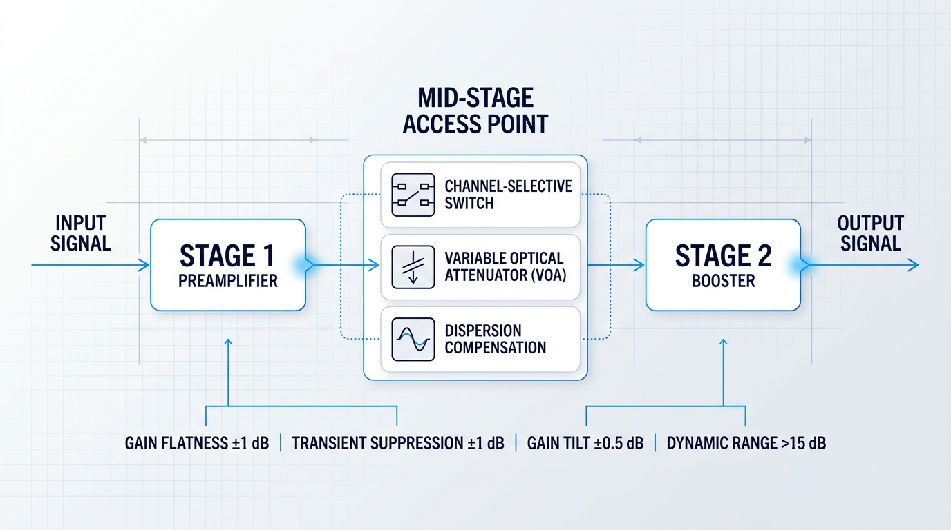
The mid-stage access point is not merely a convenience — it is what enables per-channel power management in a dynamic network, allowing channel-selective switches, variable optical attenuators (VOAs), or dispersion compensating modules to be inserted between the two gain stages without requiring separate amplifier units before and after each element.
The performance targets for a mid-stage EDFA in a metro ROADM context are specific and demanding. Gain flatness must be better than ±1 dB, transient suppression peak-to-peak must be better than ±1 dB, and gain tilt must be held to better than ±0.5 dB when 32 channels (equivalent to a 15 dB power step) are added or dropped simultaneously.
The dynamic gain range of the mid-stage EDFA must exceed 15 dB to accommodate the full range of channel loading conditions a metro node will encounter across its operational lifetime — from a single provisioned channel to a fully loaded ring.
| Parameter | Metro ROADM Target | Context |
|---|---|---|
| Gain flatness | Better than ±1 dB | Across the C-band gain window |
| Transient suppression (peak-to-peak) | Better than ±1 dB | During channel add/drop events |
| Gain tilt (32-channel add/drop) | Better than ±0.5 dB | Equivalent to 15 dB power step |
| Dynamic gain range | Greater than 15 dB | To cover single-channel to fully loaded operation |
| Transient settling time | Less than 200 µs (typical) | Faster than the ~1 ms of the fastest WSS-based ROADM |
Quantitative performance targets for mid-stage inline EDFAs in metro ROADM nodes, drawn from Lightwave Online source on metro ROADM amplification requirements.
These figures reveal why metro EDFA design is not a simplification of long-haul design. The transient suppression and gain tilt requirements are driven by the speed and frequency of channel changes — parameters that long-haul amplifiers, operating in comparatively stable channel-loading conditions, do not face at the same severity.
Cost is the other structural constraint that shapes every component decision in metro amplification. Amplification can account for approximately 20% of total metro system cost, which creates pressure to use lower-cost components wherever performance permits.
One direct consequence is the widespread use of uncooled pump lasers in metro EDFAs. Removing the thermoelectric cooler from the pump module reduces cost significantly; the resulting wavelength drift with temperature does affect amplifier performance, but not enough to disqualify the approach for metro applications where performance requirements are less stringent than in long-haul or submarine systems.
Variable gain control is the other key enabler of cost-effective metro deployment. As services are added, dropped, and reconfigured, amplifiers must adapt their gain and output power dynamically — without manual intervention — to prevent surviving channels from experiencing power imbalances at downstream receivers.
Data Centre Interconnects and the SOA's Application Identity
Data centre interconnects span a range from campus-scale links of a few kilometres to metro-scale connections between regional facilities, but they share a common set of requirements: low cost, high integration density, support for advanced modulation formats, and tolerance of bursty, packet-based traffic.
That last requirement — bursty traffic — is where the structural difference from long-haul becomes most consequential for amplifier selection. EDFAs are optimised for continuous-wave, steady-state channel loading; in bursty traffic environments, they require sophisticated gain control circuits or must be operated in a linear mode that sacrifices efficiency.
Semiconductor optical amplifiers (SOAs) handle bursty, packet-based traffic more naturally, making them well-suited to data centre interconnect and metro Ethernet applications where traffic patterns are inherently variable.
Beyond traffic handling, SOAs bring two further advantages that are directly relevant to data centre and metro contexts: integration density and wavelength range.
- PIC integration: SOAs are the only optical amplifier that can be integrated as a functional element in photonic integrated circuits (PICs), enabling co-packaged optics and high-density transceiver modules.
- Broad wavelength coverage: SOAs operate across 1060–1600 nm, including the O-band (1310 nm) used in many data centre links — well beyond the C-band and L-band window of EDFAs.
- Compact form factor: Typical SOAs are a millimetre long and less than half a millimetre wide, enabling integration where fibre-based amplifiers cannot fit.
- Fast response time: SOAs respond on nanosecond timescales, supporting optical switching and high-bit-rate packet-based systems alongside their amplification role.
The O-band coverage is particularly important for data centre applications. Many short-reach and campus-scale data centre links operate at 1310 nm rather than 1550 nm, a wavelength region where EDFAs cannot provide gain — making SOAs the only viable amplifier technology for O-band reach extension and loss compensation in these systems.
An emerging class of high-power O-band SOAs is now targeting next-generation data centre infrastructure at the scale demanded by AI and high-performance computing interconnects.
Recent O-band SOA technology has demonstrated 30 dBm (1 W) saturation output power at 1310 nm with over 20% power conversion efficiency at 50°C — performance figures that enable co-packaged optics (CPO) architectures where optical engines are integrated directly onto the same substrate as switch ASICs, eliminating the power and latency overhead of pluggable transceivers.
In O-band data centre links, bursty metro Ethernet traffic, and photonic integrated circuit applications, SOAs are not a lower-cost substitute for EDFAs — they are the only amplifier technology that fits the requirement. EDFAs cannot reach 1310 nm. They cannot be monolithically integrated into a PIC. And they do not handle bursty traffic without additional gain control circuitry. For these niches, the SOA is the primary choice, not a fallback.
That said, SOA limitations in high-channel-count WDM contexts are real and should inform amplifier selection decisions honestly.
SOA noise figures typically fall in the 6–10 dB range, compared to approximately 4 dB for a well-designed EDFA — a consequence of coupling losses at the input facet that are inherent to the semiconductor waveguide structure. Output saturation power is typically 10–13 dBm in standard devices, which is insufficient for high-channel-count DWDM systems that require significantly higher total output power.
Polarisation sensitivity is a further consideration: without optimised design (such as strained-layer active regions), SOA gain is polarisation-dependent, which complicates deployment in systems where the polarisation state of the input signal is not controlled.
These characteristics define the SOA's application boundary clearly: reach extension, single-channel loss compensation, optical switching, CWDM amplification across the full 1260–1620 nm window, and integration-focused architectures where the EDFA's form factor or wavelength range is a constraint. For high-channel-count DWDM amplification over metro or long-haul spans, EDFAs remain the appropriate choice.
The amplifier selection logic in metro and data centre applications is therefore not a hierarchy — it is a map of niches, with EDFAs dominating node amplification in ROADM-based metro networks and SOAs occupying the O-band, integration-dense, and bursty-traffic domains where fibre-based amplifiers cannot follow.
Optical sensing applications take this logic in yet another direction: when the requirement shifts to pulsed operation, high peak power, and wavelength agility for LIDAR, distributed sensing, or fibre Bragg grating interrogation, neither the continuous-wave metro EDFA nor the integration-focused SOA is the primary design reference — a different set of amplifier parameters entirely comes to the fore.
Optical Sensing: LIDAR, Distributed Sensing, and Fibre Bragg Gratings
In telecommunications, a poorly performing amplifier degrades a signal that carries known, error-correctable data. In optical sensing, a poorly performing amplifier corrupts the physical measurement itself — and there is no forward error correction for the real world. Range, spatial resolution, and detection sensitivity are all direct functions of amplifier noise figure, output power, and pulse fidelity, with far less system-level headroom to compensate than telecom engineers are accustomed to.
That constraint is the through-line across every sensing sub-domain covered here: the amplifier is not a link in a chain, it is the instrument's fundamental limit.
LIDAR: Pulsed Ranging and FMCW Architectures
Pulsed LIDAR and the MOPA Architecture
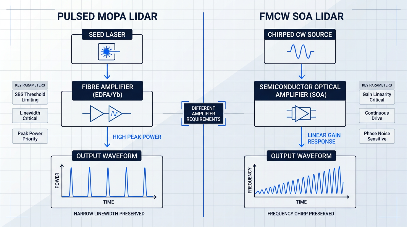
Pulsed LIDAR for long-range ranging relies on the MOPA (master oscillator power amplifier) architecture: a narrow-linewidth seed laser generates a precisely shaped pulse, which a fibre amplifier — typically an EDFA at 1550 nm or a ytterbium-doped amplifier at 1064 nm — boosts to the high peak powers required for useful target returns at distance.
Preserving the seed laser's linewidth through amplification is not optional for coherent LIDAR. The return pulse must interfere with a local oscillator copy of the original signal, and any spectral broadening introduced by the amplifier directly degrades range resolution.
Stimulated Brillouin scattering (SBS) sets a hard physical ceiling on how much pulse energy can be extracted from a given length of gain fibre — as pulse energy increases, the SBS threshold is reached and energy is back-scattered rather than forward-amplified, capping achievable peak power.
Engineers address this through a combination of shorter, more heavily doped gain fibres; phase modulation to broaden the signal linewidth just enough to raise the SBS threshold; and pulse shaping to manage the peak-power-to-duration trade-off.
Operation at 1550 nm carries a practical advantage that matters enormously for terrestrial and airborne LIDAR: the eye-safety threshold at this wavelength is substantially higher than at 1064 nm, enabling higher permissible emission levels in populated environments and simplifying regulatory approval for deployed systems.
FMCW LiDAR for Autonomous Vehicles and Solid-State Beam-Steering
FMCW (frequency-modulated continuous-wave) LiDAR transmits a chirped CW signal rather than discrete pulses, encoding range and velocity simultaneously in the frequency difference between the transmitted and returned waveforms. This architecture is increasingly favoured for automotive and autonomous vehicle applications, where it offers inherent immunity to interference from other LiDAR units and provides simultaneous velocity measurement without a separate processing step.
Semiconductor optical amplifiers at 1550 nm and 1310 nm are the preferred gain element for FMCW LiDAR. Their compact footprint and electrical drive compatibility allow integration directly onto silicon photonic integrated circuit platforms, enabling arrayed solid-state beam-steering architectures that eliminate the mechanical scanning components that are a known reliability liability in automotive-grade deployments.
The amplifier requirements for FMCW are distinct from those of pulsed LIDAR. The gain element must handle a continuous chirped waveform without distorting the frequency ramp — any nonlinearity in the amplifier's gain response introduces errors in the encoded range and velocity data.
- Low noise figure: Minimises ASE-induced phase noise on the chirped waveform, preserving the frequency ramp accuracy that encodes range and velocity.
- High small-signal gain: Ensures sufficient output power from a compact, PIC-integrable device without requiring a long gain medium that complicates chip-scale integration.
- High saturated output power: Sustains output level under continuous-wave drive across the full beam-steering array without gain compression distorting the chirp.
- Gain linearity under CW drive: Prevents amplitude and phase distortion of the frequency ramp — nonlinear gain response translates directly into range and velocity measurement errors.
These requirements collectively shape SOA selection for FMCW LiDAR in ways that differ substantially from the gain-and-bandwidth criteria that dominate telecom SOA procurement — the sensing application imposes its own logic on every amplifier parameter.
Distributed Sensing: BOTDA and DAS
Distributed sensing turns the fibre itself into a continuous sensor, extracting physical measurements — temperature, strain, acoustic vibration — from the light backscattered at every point along its length. The achievable sensing range is bounded by fibre attenuation: without amplification, the backscattered signal from distant points falls below the detection floor and the measurement is lost.
BOTDA and Hybrid Raman/EDFA Range Extension
BOTDA (Brillouin optical time-domain analysis) extracts temperature and strain profiles by measuring the frequency shift of the Brillouin backscatter signal at each point along the fibre. The technique's spatial resolution and sensing range are in direct tension: higher spatial resolution requires shorter probe pulses, which carry less energy and produce weaker backscatter, tightening the noise budget at every point in the measurement.
Hybrid Raman/EDFA amplification schemes address the range limitation by combining distributed Raman amplification along the sensing fibre with lumped EDFA gain at the terminal — extending sensing reach well beyond what either technology achieves alone.
The reason distributed Raman amplification is particularly well-suited to BOTDA is structural: because the gain is delivered along the same fibre that carries the sensing signal, the effective noise penalty is lower than a lumped EDFA placed at the fibre end would introduce. Distributed gain partially offsets attenuation continuously, keeping the signal-to-noise ratio higher throughout the sensing length.
DAS and Ultra-Long-Range Coherent OTDR
DAS (distributed acoustic sensing) uses coherent OTDR to detect dynamic strain events along the fibre — acoustic vibrations from pipeline leaks, intruder footsteps on a perimeter, seismic activity, or passing trains — by measuring phase changes in the Rayleigh backscatter at each point. The technique is seeing rapid adoption in pipeline monitoring, perimeter security, railway infrastructure, and subsea cable monitoring.
Unamplified DAS systems face a fundamental range limitation: the coherent backscatter signal from points far along the fibre is too weak to resolve against the noise floor, restricting single-ended sensing to distances insufficient for many real-world deployments, particularly long pipelines and subsea infrastructure where installing a second terminal is operationally impractical.
Combined distributed Raman amplification and remotely optically pumped amplifiers (ROPA) in erbium-doped fibre extend DAS sensing range dramatically, enabling single-ended sensing over ultra-long fibres from a single terminal — operationally significant for subsea and remote infrastructure deployments where a second access point may not exist.
In telecom, ASE noise degrades OSNR but the underlying data can be recovered through forward error correction. In sensing, the return signal is the physical world's response to the probe — there is no error correction for a corrupted measurement. Noise figure and ASE management are therefore categorically more consequential in sensing than in most telecom contexts.
The ROPA architecture introduced in submarine cable systems — where pump light is delivered remotely over the fibre to power an in-line erbium-doped amplifier — reappears here in a sensing context, demonstrating that the same fundamental approach to remote amplification serves both ultra-long transmission and ultra-long sensing deployments.
Fibre Bragg Grating Interrogation
FBG (fibre Bragg grating) interrogation is a quasi-distributed sensing technique in which discrete gratings written into the fibre at known positions each reflect a specific wavelength. Temperature, strain, or pressure at each grating location shifts that reflection wavelength, and the interrogation system measures those shifts across the full array to reconstruct the physical field along the fibre.
The amplifier's role in FBG interrogation is to provide sufficient illumination across potentially large grating arrays — tens to hundreds of FBGs spanning wide wavelength ranges — while maintaining the spectral flatness and power stability that accurate interrogation demands.
An EDFA source with uneven gain across the FBG reflection band introduces systematic errors: gratings in high-gain spectral regions appear to shift differently from gratings in low-gain regions, creating artefacts that are indistinguishable from real physical changes in the structure being monitored.
The choice between a broadband ASE source and a narrowband tunable source depends on the measurement priority. Broadband ASE sources offer wide spectral coverage and suit large arrays where illuminating many FBGs simultaneously matters more than wavelength resolution; narrowband tunable sources sacrifice spectral breadth for precision and are preferred when resolving small wavelength shifts is the primary requirement.
Amplifier power stability is equally critical: drift in the source output level between measurement cycles introduces apparent wavelength shifts that corrupt the time-series data used for structural health monitoring, where detecting slow progressive changes over months or years depends entirely on a stable, repeatable interrogation baseline.
The sensing applications covered here all share the same underlying logic — amplifier noise, stability, and output characteristics are the direct determinants of what the system can measure, how far it can reach, and how accurately it can resolve physical events. The next section extends this principle into its most demanding expression: fibre optic gyroscopes, where the amplifier's own spontaneous emission is the sensing medium, and managing that noise is not a matter of system-level compensation but of fundamental amplifier design.
Fibre Optic Gyroscopes: When ASE Becomes the Source
Every application covered so far in this guide uses optical amplifiers in the same fundamental role: restoring signal power that attenuation or insertion loss has consumed. Fibre optic gyroscopes break that pattern entirely. In a fibre optic gyroscope (FOG), erbium-doped fibre technology does not condition a signal — it is the source.
The operating principle is the Sagnac effect: counter-propagating light beams traverse a fibre coil in opposite directions, and rotation introduces a phase difference between them proportional to the rotation rate. Detecting that phase difference with interferometric precision is how the gyroscope measures angular velocity.
The critical consequence for light source design is direct: the spectral characteristics of whatever illuminates the coil set hard limits on gyroscope performance. Phase measurement noise, drift mechanisms, and scale factor stability all trace back, in part, to properties of the source. This is why the choice of light source in a high-performance FOG is not a peripheral engineering detail — it is a primary design constraint.
Why Broadband ASE Outperforms Coherent Laser Sources
The intuition from communications is that ASE — the broadband spontaneous emission produced by erbium-doped fibre, familiar as the noise floor in EDFAs — is something to be minimised. In FOG design, that intuition inverts completely.
The first physical reason to prefer broadband ASE is its effect on birefringence-induced non-reciprocity. Any real fibre coil contains residual birefringence, which causes polarisation-dependent phase shifts. A coherent, polarised laser source is acutely sensitive to this: even small birefringence variations translate into gyroscope bias errors. Broadband, unpolarised ASE emission averages over these polarisation states, suppressing the non-reciprocity that a coherent source would amplify.
The second reason is more subtle and physically striking. The optical Kerr effect — a nonlinear interaction arising from intensity-dependent changes in the refractive index of the silica fibre core — can produce a nonreciprocal phase difference between the counter-propagating beams whenever their power levels are even slightly imbalanced. In a navigation-grade FOG, a power difference of just 1 µW arising from a splitting imbalance of 10⁻³ in a 1 mW source is sufficient to generate a phase error several orders of magnitude above the theoretical sensitivity limit.
The Kerr-induced phase shift is nulled when the mean value of the source intensity equals its standard deviation — and this is precisely the statistical property of broadband spontaneous emission. As Lefèvre's SPIE monograph describes it, this is "the ultimate serendipity" of the ASE source: its intensity statistics naturally satisfy the condition that cancels Kerr-induced drift, a condition a coherent laser cannot meet.
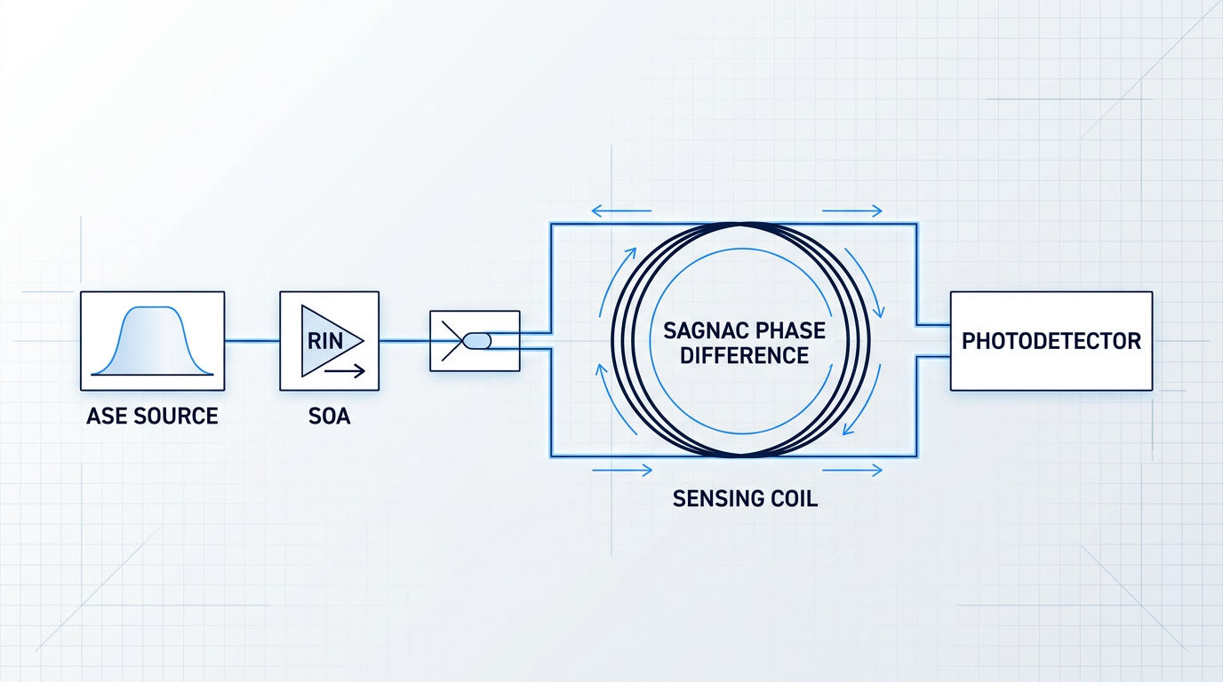
ASE is not chosen despite being spectrally broad and incoherent — it is chosen because those properties simultaneously suppress birefringence non-reciprocity and null the Kerr effect. No coherent laser source can replicate both mechanisms.
In FOG design, the broadband, incoherent, unpolarised nature of erbium ASE — properties that communications engineers treat as liabilities — are precisely the physical characteristics that suppress birefringence non-reciprocity and null the optical Kerr effect. A coherent laser source cannot replicate either mechanism.
RIN Suppression and the Path to Navigation-Grade Stability
Choosing ASE as the source does not eliminate all noise concerns. Relative intensity noise (RIN) — power fluctuations in the ASE output — propagates directly into gyroscope bias error, because the Sagnac interferometer converts intensity variations into apparent rotation-rate signals.
SOA-based RIN suppression addresses this by exploiting the gain saturation behaviour of a semiconductor optical amplifier (SOA): as input power fluctuates, the SOA's gain responds inversely, partially stabilising the output intensity. Research published in SPIE Proceedings Volume 13511 demonstrates that after SOA suppression, the RIN of the source is reduced by more than 10 dB.
The performance improvements at the gyroscope level are substantial. The same research reports that bias stability improves by 28.3%, the angle random walk coefficient improves by 51.9%, and full-temperature bias stability improves by 23% — all directly attributable to the RIN reduction.
Translating these results from the laboratory to a fielded navigation system requires careful attention to temperature behaviour. The spectral characteristics of both the ASE source and the SOA shift with temperature, and their interaction can introduce wavelength glitches that degrade gyroscope performance across the operating range. The SPIE Vol. 13511 research identifies a 1530 nm Gaussian spectrum ASE combined with a matched SOA and an additional 1530 nm Gaussian filter at the SOA output as the optimal engineering combination — a solution that suppresses temperature-induced wavelength instability while preserving the RIN benefit.
Scale Factor Stability and FBG Wavelength Filtering
The scale factor of an interferometric FOG — the conversion coefficient between measured phase difference and rotation rate — depends directly on the mean wavelength of the light source. Any drift in mean wavelength produces a proportional error in the rotation rate output, regardless of how well bias stability and RIN are controlled.
The engineering solution, documented in SPIE Proceedings Volume 2837, is to use a fibre Bragg grating (FBG) as a broad spectral filter on the ASE output. The FBG's reflection band defines a stable spectral window, constraining the mean wavelength of the light entering the coil. Gaiffe et al. demonstrated that this approach achieves 10 ppm wavelength stability over temperature — a level sufficient for navigation-grade scale factor performance.
It is worth noting that this is a distinct application of FBG technology from the interrogation and strain-sensing uses covered earlier in this guide. Here, the FBG is not a sensing element — it is a spectral engineering tool applied to the light source itself, shaping the emission that enters the gyroscope coil.
Navigation-Grade vs Tactical-Grade: What the Specifications Demand
Not every FOG application requires the full complexity of ASE source engineering, SOA-based RIN suppression, and FBG wavelength stabilisation. The FOG performance hierarchy divides broadly into two tiers, and the engineering investment required differs substantially between them.
- Navigation-grade FOGs: For aircraft, submarine, and spacecraft inertial navigation. Require bias uncertainty below 0.015 deg/hr, angle random walk below 0.005 deg/√hr, and scale factor errors below 50 ppm.
- Tactical-grade FOGs: For missiles, smart munitions, and attitude/heading reference systems. Operate with bias performance of 1–10 deg/hr and scale factor performance of 100–1000 ppm.
The performance gap between these tiers is not incremental — it spans several orders of magnitude in bias stability and angle random walk. Navigation-grade performance, as reported in SPIE Vol. 2837, has reached bias uncertainties of 0.0081 deg/hr over the −55 to +71 °C temperature range, with angle random walk as low as 0.0009 deg/√hr.
Tactical-grade designs can tolerate simpler light sources — including sub-threshold laser diodes operating as low-coherence broadband emitters — because their bias and scale factor specifications are orders of magnitude more relaxed. The amplifier source engineering described in this section is not universal; it is the navigation-grade requirement that justifies it.
Hollow-Core Photonic Bandgap Fibre: Changing the Coil Changes the Source
An emerging approach replaces the conventional solid-core sensing coil with a hollow-core photonic bandgap fibre (HC-PBF) coil, in which the fundamental mode propagates primarily in air rather than silica glass.
The physical motivation is compelling. Air has a far weaker temperature dependence of refractive index than silica, substantially reducing long-term thermal drift from the Shupe effect caused by temperature gradients across the coil. Air also has a much weaker Kerr nonlinearity than silica. Experimental results reported by SPIE document a 6.5-fold reduction in thermal drift and a 250-fold reduction in the effective Kerr constant compared to a conventional solid-core FOG.
These results carry a significant implication for light source selection. The Kerr effect suppression that makes broadband ASE necessary in a solid-core coil is largely addressed by the hollow-core waveguide geometry itself. With the Kerr mechanism neutralised at the coil level, the FOG becomes compatible with narrow-linewidth laser sources — sources that offer superior mean wavelength stability and eliminate excess source noise, but that would cause unacceptable Kerr-induced drift in a solid-core coil.
This is an instructive illustration of the application-first principle that runs through this guide: within a single application domain, changing one system component — the coil — changes the optimal choice for another — the light source. The engineering logic that makes ASE the preferred source for solid-core FOGs does not transfer automatically to hollow-core designs.
With the precision sensing arc now complete — from distributed sensing and FBG interrogation through to the inertial navigation demands of FOG design — the guide turns to the most frontier applications of optical amplifiers: biomedical imaging and all-optical signal processing, where amplifier technology is pushing into domains that were largely inaccessible a decade ago.
Biomedical Imaging and All-Optical Signal Processing: Amplifiers at the Frontier
Every application covered so far in this guide uses optical amplifiers to serve a network or sensing system that exists independently of the amplifier itself. The two domains in this section are different: in optical coherence tomography and in all-optical signal processing, the amplifier's physical properties are not incidental to the application — they are constitutive of it.
The amplifier's spectral bandwidth determines what tissue depth an OCT system can resolve; the SOA's carrier dynamics determine whether wavelength conversion happens at all. These are the applications where amplifier physics and application physics are genuinely inseparable.
Biomedical Imaging: OCT and Fluorescence Microscopy
The governing principle of OCT is that axial resolution — depth discrimination within tissue — is inversely proportional to the spectral bandwidth of the light source: the broader the spectrum, the shorter the coherence length, and the finer the depth resolution achievable.
This relationship is not merely a design preference; it makes every amplifier spectral parameter directly clinically relevant, because a change in source bandwidth translates immediately into a change in how finely the system can distinguish tissue layers.
In OCT, axial resolution scales inversely with source spectral bandwidth — so amplifier gain profile shape, spectral flatness, and usable bandwidth are not abstract optical specifications. They determine the spatial resolution at which tissue microstructure can be imaged.
Swept-Source OCT and the SOA Gain Medium
In swept-source OCT, the light source must sweep rapidly across a wide wavelength range while maintaining a narrow instantaneous linewidth — a requirement that makes the SOA's physical architecture uniquely suited to the task.
Because the SOA gain medium is approximately 1 mm long, the round-trip time within a swept-source cavity is extremely short, enabling sweep rates that long-fibre gain media cannot approach: systems using time-stretched supercontinuum combined with SOA-based amplification have demonstrated swept-source operation at 10 MHz A-scan rates, with sweep linearity exceeding 0.99998.
A different architecture — a compact 1300 nm swept source using a MEMS mirror with an SOA gain element — demonstrates what the technology delivers at more modest sweep rates: a 40 kHz system with a 10 mm coherence length and OCT sensitivity of 105 dB, packaged in a butterfly form factor suitable for clinical instrument integration.
The SOA gain profile shape matters as much as the bandwidth figure: a non-uniform gain spectrum reshapes the instantaneous output spectrum during the sweep, and this spectral distortion propagates directly into the point-spread function of the OCT system, degrading axial resolution in a way that cannot be corrected purely in post-processing.
ASE and Supercontinuum Sources for OCT
ASE from erbium-doped and ytterbium-doped fibres provides an alternative source architecture for time-domain and spectral-domain OCT: the emission is inherently broadband, spatially incoherent, and unpolarised, giving it a naturally short coherence length well suited to low-coherence interferometry without the speckle artefacts associated with laser sources.
Hybrid broadband sources combining cascaded SOA and erbium-doped fibre stages have demonstrated usable spectral bandwidths exceeding 120 nm, with OCT systems configured around such sources achieving sensitivities of 106 dB and axial resolutions in the 10–12 µm range in tissue.
For applications requiring finer depth resolution, supercontinuum generation offers a qualitatively different capability: a fibre amplifier chain pumping a highly nonlinear photonic crystal fibre produces a spectrally continuous output spanning several hundred nanometres, supporting axial resolutions in the 1–5 µm range in tissue — approaching cellular-scale imaging.
The engineering challenge with supercontinuum sources is noise: conventional long-pulse supercontinuum generation is seeded by modulation instability, producing pulse-to-pulse intensity fluctuations that push the OCT system away from the shot-noise-limited sensitivity regime and limit penetration depth.
Supercontinuum sources based on all-normal-dispersion fibres pumped by femtosecond pulses avoid this problem by confining spectral broadening to coherent processes — self-phase modulation and optical wave-breaking — producing low-noise spectra that enable shot-noise-limited OCT operation, with demonstrated sensitivity of 96 dB and axial resolution of 5.9 µm at 1370 nm.
Amplifier Parameters That Govern OCT Performance
Three amplifier parameters translate most directly into OCT system performance, and engineers designing OCT sources must treat each as a first-order design variable rather than a secondary specification.
- Noise figure and sensitivity: Amplifier noise figure sets the floor for shot-noise-limited sensitivity; excess RIN from the source directly limits maximum achievable OCT sensitivity and penetration depth.
- Gain profile and axial resolution: Non-uniform SOA gain across the sweep bandwidth reshapes the effective source spectrum, broadening the coherence function and degrading the system's axial point-spread function.
- Polarisation-mode dispersion: PMD in the gain fibre introduces wavelength-dependent group delay, reducing the effective coherence length of the source and limiting achievable axial resolution.
Managing these three levers simultaneously is the core engineering task in OCT source design: optimising noise figure improves sensitivity, but gain-flattening to control spectral shape can reduce usable bandwidth, and PMD mitigation often requires polarisation-maintaining fibre that adds cost and integration complexity.
MOPA Chains for Multiphoton Fluorescence Microscopy
Two-photon fluorescence microscopy requires peak powers in the kilowatt range to drive efficient nonlinear excitation — a requirement that makes MOPA fibre amplifier chains the practical route to achieving these power levels from compact, stable sources.
The principal engineering constraint in MOPA chains for microscopy is nonlinear degradation within the gain fibre itself: as pulse energy scales up, self-phase modulation broadens the pulse spectrum and distorts the temporal profile, while stimulated Raman scattering transfers energy out of the signal band — both effects reducing the peak power available at the sample.
Mitigation strategies include using large-mode-area gain fibres to reduce intensity per unit area, keeping gain fibre lengths as short as possible, and in some configurations employing chirped-pulse amplification to stretch the pulse before amplification and recompress it afterwards — trading system complexity for preserved pulse quality at high peak powers.
All-Optical Signal Processing
Every time an optical signal is converted to electrical for processing and then back to optical, the system pays a cost in latency, power consumption, and bandwidth ceiling — a cost that grows more severe as network capacities scale toward terabit-per-second rates.
All-optical signal processing avoids this optoelectronic conversion bottleneck by performing wavelength conversion, switching, and regeneration entirely in the optical domain, and the SOA is the primary platform: compact, integrable on-chip with passive waveguides, and uniquely capable of providing internal gain while simultaneously performing the nonlinear function.
The nonlinear behaviour of the SOA arises from its carrier dynamics — when an input signal modulates the carrier density, it simultaneously modulates both the gain and the refractive index of the gain medium, and these coupled effects underpin three distinct mechanisms for all-optical processing.
- Cross-gain modulation (XGM): The data signal saturates SOA gain, imprinting an inverted copy of its pattern onto a CW probe at a new wavelength. Simple and fast, but inverts the signal and degrades extinction ratio.
- Cross-phase modulation (XPM): In an SOA-MZI configuration, the data signal modulates SOA refractive index; the interferometer converts the resulting phase shift to amplitude modulation with better extinction ratio than XGM.
- Four-wave mixing (FWM): A parametric process generating new wavelengths at defined frequency offsets. Preserves phase information, making it suitable for coherent modulation formats and optical dispersion compensation.
Cross-gain modulation is the simplest architecture — a single SOA, no interferometer — and has demonstrated wavelength conversion at 100 Gbit/s, but the signal inversion and extinction ratio degradation it introduces are significant practical penalties for high-sensitivity receivers.
Cross-phase modulation in the SOA-Mach-Zehnder interferometer configuration addresses both penalties: the interferometric stage converts phase modulation to intensity modulation without inversion, and the differential configuration suppresses ASE noise, making SOA-MZI the preferred architecture where both speed and signal quality matter.
Four-wave mixing occupies a distinct niche: as a parametric process it is inherently phase-preserving, which makes it the mechanism of choice for wavelength conversion of coherent modulation formats such as DQPSK, where amplitude-based mechanisms cannot transfer phase information — a capability demonstrated at 320 Gbit/s in highly nonlinear fibre.
These demonstrations confirm that the physics of all-optical processing is not the limiting factor; the limiting factor is deployment.
Practical devices that simultaneously combine the integration density, tunability, and high-speed operation that real network nodes require have not yet converged into commercially deployable products, and the reasons are as much architectural as they are technical.
Whether future high-capacity networks will adopt optical packet switching or optical circuit switching remains an open question, and the answer determines which all-optical processing technology is worth optimising for production — a form of architectural uncertainty that makes it rational for vendors to hold investment in any single approach.
Optical packet switching demands fast, fine-grained decisions at each node, which requires optical buffer memory — a component that has proved substantially harder to realise than the switching elements themselves, and whose absence continues to constrain the path from laboratory demonstration to deployed system.
The honest engineering assessment is that all-optical processing based on SOA nonlinearities represents some of the most technically impressive work in the field, but the gap between what has been demonstrated in the lab and what is ready for network operators to deploy remains wide and is not primarily a physics problem.
Across both domains covered in this section — biomedical imaging and all-optical signal processing — the recurring theme is that amplifier properties are not secondary to the application: they define it, constrain it, or in some cases make it possible at all. That pattern, and what it means for engineers choosing between standard and custom amplifier solutions, is what the guide's conclusion addresses next.
Conclusion
Choosing the Right Optical Amplifier: From Application Requirements to Implementation
Across every domain covered here, the pattern is the same: the amplifier technology that wins is the one the application demands, not the one with the strongest headline specification.
What the research literature rarely captures — but practitioners know well — is that environmental qualification, pump laser lifetime, and integration complexity are where real projects are won or lost.
When standard telecom-grade hardware cannot meet the specification, custom amplifier design is not a workaround; it is the appropriate engineering response.
Frequently Asked Questions About Optical Amplifier Applications
Common questions about optical amplifier types, applications, and selection — answered directly for engineers, researchers, and procurement specialists.
Choose EDFA when you need high-power, low-noise amplification across multiple WDM channels in the C-band or L-band — particularly for long-haul terrestrial links, submarine cables, and high-channel-count DWDM systems. Choose SOA when integration density is the priority, when your operating wavelength falls outside the EDFA window (such as the O-band at 1310 nm), when traffic is bursty or packet-based, when nonlinear signal processing functions like wavelength conversion are required, or when cost constraints in metro and access deployments make EDFA impractical. Raman amplification is a third option worth considering: it complements EDFA in demanding long-haul and distributed sensing contexts by providing gain directly in the transmission fibre, improving noise performance without adding a discrete amplifier node.
Optical amplifiers are deployed across a wide range of real infrastructure: transoceanic submarine cables, terrestrial long-haul fibre backbones, metro ROADM networks, and data centre interconnects all rely on them to compensate for fibre attenuation and maintain signal integrity across distance. Beyond telecommunications, they appear in less obvious but equally established contexts. MOPA architectures using fibre amplifiers boost seed laser pulses in autonomous vehicle LiDAR systems. SOA-based swept-source configurations power medical optical coherence tomography (OCT) scanners. Fibre optic gyroscopes (FOGs), used in inertial navigation systems for aerospace and defence, exploit the broadband ASE output of fibre amplifiers as a low-coherence light source rather than as a signal booster.
An optical amplifier boosts an optical signal directly in the optical domain, with no conversion to an electrical signal. A repeater, by contrast, performs full optoelectronic conversion: it detects the incoming optical signal, processes it electrically, and retransmits a regenerated version. This distinction has significant practical consequences. Optical amplifiers are protocol-transparent — they amplify the light regardless of modulation format or data rate — and can amplify dozens of WDM channels simultaneously with a single device. They are also simpler and more scalable than repeater chains. The trade-off is noise: each amplifier stage adds amplified spontaneous emission (ASE), which accumulates along a cascade. Repeaters eliminate that noise accumulation by regenerating a clean signal at each node, but they introduce latency, protocol dependence, and higher per-node cost.
Optical amplifiers are used across four broad domains. In telecommunications, they are fundamental to long-haul fibre networks, WDM and DWDM systems, submarine cables, metro networks, and data centre interconnects. In optical sensing, they enable long-range LIDAR, distributed temperature and strain sensing along fibre spans, and fibre Bragg grating interrogation systems. In precision navigation, fibre optic gyroscopes use the broadband ASE output of fibre amplifiers as a stable low-coherence source for inertial measurement. In biomedical imaging, SOA-based and fibre-based amplifiers underpin optical coherence tomography and fluorescence microscopy systems. An emerging fifth domain is all-optical signal processing, where SOA nonlinearities enable wavelength conversion and optical switching functions without any optoelectronic conversion — keeping signals entirely in the optical domain.
The two types are direct-detection receivers, which use a photodiode to measure the intensity of the incoming optical signal, and coherent receivers, which mix the signal with a local oscillator laser to recover both amplitude and phase — enabling advanced modulation formats such as QPSK and QAM. Optical amplifiers serve both receiver types as optical preamplifiers, boosting the signal before detection to improve receiver sensitivity. However, the demands they place on amplifier performance differ significantly. Coherent receivers, used in high-capacity long-haul systems, are sensitive to optical nonlinearities and require tighter control of amplifier noise figure, OSNR degradation, and nonlinear phase noise arising from self-phase modulation (SPM) and cross-phase modulation (XPM). Direct-detection systems are generally more tolerant of these effects, which is why amplifier specifications differ between the two system contexts.