

Introduction
Whether you work in engineering, procurement, or project management — or you simply find yourself regularly signing off on fabricated components without a clear picture of how they are made — this guide is for you.
Metal fabrication is a discipline with genuine depth: a structured, engineered process in which deliberate decisions at every stage shape the quality, performance, and longevity of the finished part.
What follows is a stage-by-stage walkthrough of the full process, covering the materials involved, the sectors that depend on it, and the quality standards that professional fabricators work to.
TL;DR
Fabrication is far more than cutting and welding. Every stage — from the first engineering drawing to the final quality inspection — involves decisions that directly determine whether a finished part performs as intended. Understanding the full process reveals why material choice, process sequencing, and tolerance control matter as much as the metalwork itself.
This article covers:

Metal fabrication vs. manufacturing: the key difference
The fabrication process: design through quality inspection
Common materials: steel, aluminium, and alloys
How cutting methods compare and when each applies
Industries that rely on metal fabrication
Quality assurance and tolerances in fabrication
What Is Fabricating?
The steel staircase in an office block, the frame of an agricultural machine, the pressure vessel in an industrial plant — behind virtually every metal structure or component in the built environment sits the same foundational process: metal fabrication.
In an industrial context, fabricating means transforming raw or semi-finished metal materials into finished structures or component parts through processes including cutting, bending, welding, and assembling. (The everyday sense of the word — to invent or deceive — is a different matter entirely; this guide concerns itself only with the industrial one.)
The scope of what fabrication produces is deliberately wide. At one end: simple brackets, hand railings, and staircases. At the other: structural steelwork for bridges, heavy equipment frames, pressure vessels, and large machinery enclosures.
That breadth is the point. Metal fabrication is not a niche specialism but a foundational industrial discipline — one that underpins construction, infrastructure, and manufacturing at large.
Fabrication vs Manufacturing: What Is the Difference?
Manufacturing refers to the complete production chain: raw materials go in at one end, a finished, consumer-ready product comes out at the other, with all intermediate steps handled within the same process.
Fabrication, by contrast, produces the sub-assemblies and component parts that feed into that chain — it is one stage, or a set of stages, within the broader manufacturing process, not the whole of it.
In practice, the boundary between the two is not always clean. A single company may take raw metal stock, fabricate parts from it, and then assemble a finished product — occupying both roles simultaneously. The terms are also used interchangeably in industry, which is precisely why the distinction trips people up.
Manufacturing encompasses the entire production chain from raw material to finished product. Fabrication is the set of processes — cutting, bending, welding, assembling — that creates the parts that chain depends on.
In practice, fabrication work is carried out by a specialised fabrication shop (commonly called a fab shop) — a facility equipped with cutting, forming, and welding machinery that bids on contracts based on engineering drawings and specifications supplied by the client or design team.
Understanding what a fabrication project actually looks like in practice starts one step earlier than the shop floor — with the engineering drawings and design work that define exactly what needs to be built.
Design and Engineering: Where Fabrication Begins
Before a single piece of metal is cut, drilled, or bent, a fabrication project exists entirely as information — dimensions, geometries, tolerances, and material specifications captured in a design document that every downstream process will be measured against.
Engineering Drawings and the Design Document
Traditionally, fabrication began with hand-drafted engineering drawings: precise technical illustrations that specified every dimension and feature of a part.
In modern practice, those drawings have largely been replaced — or supplemented — by digital CAD (Computer-Aided Design) models, which define the same information with greater precision and significantly less room for misinterpretation.
Where a hand sketch depends on the reader's interpretation, a digital model encodes geometry exactly — and that exactness is what makes it the authoritative source of truth for the entire fabrication workflow.
From CAD Model to Machine Instructions
A CAD model defines what a part is: its three-dimensional geometry, the tolerances it must hold, and the material it will be made from.
But a CAD model alone cannot drive a machine — that is the job of CAM (Computer-Aided Manufacturing) software, which takes the CAD model as its input and translates it into machine-readable instructions.
The output of CAM software is typically G-code: a programme of precise coordinates and movement commands that tells a machine exactly where to move, at what speed, and to what depth.
If CAD defines what the part is, CAM defines how to make it — and this pipeline between the two allows a digital design to become a physical component without a skilled operator re-interpreting the drawing at every step.
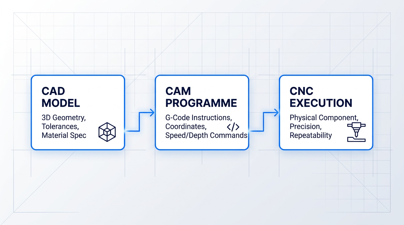
This pipeline is the backbone of modern fabrication: each stage hands off a more specific set of instructions to the next, progressively narrowing the gap between design intent and physical reality.
CNC: The Execution Layer
CNC (Computer Numerical Control) machines are the automated tools that execute the G-code programme — mills, lathes, press brakes, and cutting machines that perform operations by following programmed instructions rather than manual guidance.
The defining characteristics of CNC execution are precision and repeatability: the machine holds tolerances that manual methods cannot reliably match, and the same programme produces the same result on the hundredth part as on the first.
Human judgement is concentrated at the design and setup stages — once the programme runs, the machine follows it exactly, which is where the reduction in human error comes from.
This is also why errors in fabrication so often trace back to the design stage rather than the shop floor: a mistake in the CAD model propagates through every part the CNC machine produces from that programme.
Nesting Software and Material Efficiency
One further layer of digital planning sits between the CAD model and the cutting machine: nesting software, which arranges multiple part geometries across a sheet or plate of raw material to minimise offcuts and reduce waste.
Nesting connects individual part designs to the practical reality of material stock — it is the point at which design geometry meets production efficiency, and it is an integral part of how professional fabrication shops plan a cutting run.
Because CNC machines execute exactly what the programme tells them, a flaw introduced at the CAD stage is not caught by the machine — it is replicated across every part in the run. Getting the design right is not just the first step; it is the most consequential one.
The design phase, then, determines far more than shape: it sets the tolerances the finished part must hold, specifies the material to be used, and drives the digital programmes that every subsequent stage of fabrication will follow.
That material specification is itself a significant engineering decision — and choosing between steel, aluminium, or a specialist alloy carries trade-offs that the next section examines in depth.
Material Selection: Steel, Aluminium, and Alloys
Two parts with identical geometry, cut to identical dimensions, can behave completely differently on the shop floor — because the material specification changes everything downstream.
Material selection is not a procurement afterthought; it is an engineering decision made at the design stage, and it governs which cutting methods are viable, how the metal will respond under bending and forming, what welding procedures are required, and what surface protection the finished part will need in service.
Fabrication works with three primary material families: steel (including mild, high-strength, and stainless grades), aluminium, and the broader category of engineered alloys within each family — and the choice of grade within a family matters as much as the choice of family itself.
Steel: The Fabrication Industry's Default Material
Steel is an alloy of iron and carbon, and it is the most widely used metal in fabrication by a considerable margin.
The carbon content is the primary lever: as carbon increases from around 0.05% up toward 2.1%, the steel becomes progressively harder and stronger but also less ductile and more difficult to form, weld, and machine.
Mild steel (low-carbon steel, typically 0.05–0.25% carbon) is the workhorse of the fabrication industry — it is highly weldable, readily formable, and relatively inexpensive, making it the default choice for structural frames, enclosures, brackets, and general fabrication work.
A common structural grade, ASTM A36, exemplifies why mild steel dominates: with a yield strength of around 250 MPa and elongation at break of 20–23%, it bends without cracking, welds without special preheat procedures in most thicknesses, and machines predictably.
High-strength and alloy steels are engineered for applications where mild steel's yield strength is insufficient — by adding alloying elements such as chromium, molybdenum, vanadium, niobium, and nitrogen, manufacturers can raise yield strengths well beyond 350 MPa while maintaining reasonable toughness.
The trade-off is real: as alloying increases, formability typically decreases, springback during bending increases, and welding procedures become more demanding — higher carbon equivalents mean a greater risk of heat-affected zone cracking, often requiring preheat and low-hydrogen electrodes.
Stainless Steel: Corrosion Resistance and Its Trade-offs
Stainless steel is a distinct sub-family of steel defined by a minimum chromium content of around 10.5%, which causes a thin, self-healing chromium oxide layer to form spontaneously on the surface — and it is this passive layer that provides corrosion resistance, not a coating that can be stripped away.
The most widely fabricated stainless grades are the austenitic family, which accounts for around 70% of all stainless steel produced: Grade 304 (18% chromium, 8% nickel) is the general-purpose standard, while Grade 316 adds 2–2.5% molybdenum to improve resistance to chlorides, making it the preferred choice for marine and chemical processing environments.
Stainless steel is not simply a better version of mild steel — it is a different material with different fabrication demands.
Austenitic grades work-harden rapidly during cold forming, which means forming forces can be approximately double those required for low-carbon steel, and progressive forming operations may require intermediate annealing to restore ductility between stages.
Welding stainless introduces the risk of sensitisation: when the weld zone is held in the 450–850°C range, chromium carbides can precipitate at grain boundaries, depleting the surrounding metal of chromium and undermining its corrosion resistance — a risk managed by using low-carbon grades such as 304L or 316L, which contain less than 0.03% carbon.
Stainless steel is also significantly more expensive than mild steel, so specifying it where mild steel with a protective coating would suffice adds unnecessary cost; in genuinely corrosive environments, however, it is often the correct and most cost-effective long-term choice.
Aluminium: Lightweight Performance in Fabrication
Aluminium is the second most widely used fabrication metal after steel, and its defining characteristic is density: at approximately 2.7 g/cm³, it is roughly one-third the density of steel (around 7.8–7.9 g/cm³), making it the natural choice wherever weight is a primary constraint.
Despite its low density, aluminium alloys can achieve impressive strength-to-weight ratios — pure aluminium has a tensile strength of only around 90 MPa, but alloyed grades can exceed 570 MPa, which is why aluminium underpins aerospace structures and automotive lightweighting programmes.
Aluminium also forms its own protective oxide layer on exposure to air, providing natural corrosion resistance without the need for additional coatings in many environments — a practical advantage that reduces downstream finishing requirements.
Aluminium is generally formable, but its behaviour under bending differs meaningfully from steel: its elastic modulus is roughly one-third that of steel (approximately 68–69 GPa versus 200 GPa), which produces greater springback for a given bend geometry, and tight-radius bends carry a higher risk of cracking than equivalent operations on mild steel.
Aluminium is weldable, but requires different procedures: the natural oxide layer must be removed by stainless steel brush cleaning before welding, and the metal's high thermal conductivity — approximately three times that of steel — demands higher heat input to achieve adequate fusion.
Grades and Alloys: Why the Specification Matters
Neither "steel" nor "aluminium" is a single material — each is a family of hundreds of engineered grades, and the grade specification on an engineering drawing determines how the metal will behave at every subsequent stage of fabrication.
Within the aluminium family, the 6000-series alloys (such as 6061, which combines magnesium and silicon for good strength, formability, and weldability) are the most common choice for general structural fabrication, while the 7000-series alloys (such as 7075, which uses zinc and magnesium to achieve tensile strengths above 570 MPa) are engineered for high-strength aerospace applications where weldability is a secondary concern.
Within steel, the alloy grade controls the balance between strength, toughness, hardenability, machinability, and corrosion resistance — a fabricator receiving a drawing specifying AISI 4140 (a chromium-molybdenum alloy steel engineered for fatigue and wear resistance) will approach cutting, forming, and welding very differently from one working with A36 mild steel.
Specifying 'steel' or 'aluminium' on an engineering drawing is only half the decision. The alloy grade within that family determines formability, weldability, corrosion behaviour, and surface finishing requirements at every downstream stage of fabrication.
The practical implication is that fabricators and engineers navigate several competing trade-off axes simultaneously when selecting a material and grade — there is no universally correct answer, only the material that best satisfies all the application's requirements together.
- Strength vs weight: Steel delivers high strength per unit volume but is dense. Aluminium is far lighter, though less stiff for a given cross-section, requiring design adjustments to compensate.
- Weldability vs strength: Mild steel is the most forgiving material to weld. Higher-strength alloys — in both steel and aluminium — introduce greater weld complexity, cracking risk, and procedure demands.
- Corrosion resistance vs cost: Stainless steel and aluminium resist corrosion inherently. Mild steel requires protective coatings, adding downstream cost that must be weighed against the lower raw material price.
- Formability vs performance: Higher-strength grades in any family are harder to form, exhibit more springback, and are less tolerant of tight-radius bends than their lower-strength counterparts.
These trade-offs are not sequential choices — a fabricator must satisfy all of them simultaneously for the specific application, which is why material selection is treated as an engineering decision rather than a catalogue selection.
With material selected, the first physical transformation can begin — and the choice of material will directly shape which cutting method is used and how it must be configured.
Cutting Methods in Metal Fabrication
With engineering drawings finalised and material selected, the fabrication process makes its first physical mark on the raw stock — and that mark is a cut.
Cutting converts plate, sheet, and structural sections into the specific shapes and sizes defined by the design. It is the stage where the geometry on screen becomes geometry in metal, and the method chosen determines the edge quality, dimensional accuracy, and downstream finishing requirements for everything that follows.
Four methods dominate modern metal fabrication: laser cutting, plasma cutting, waterjet cutting, and mechanical shearing. Each operates on a different physical principle, excels within a different set of conditions, and involves trade-offs that make it the right — or wrong — choice depending on the job.
Laser Cutting
A focused beam of light is directed along a programmed path, heating the metal until it melts or vaporises; cutting gas then blows the molten material clear of the kerf (the width of material removed by the cut).
Laser cutting's defining strength is precision. According to The Fabricator, tolerances of ±0.001 to ±0.006 in. are achievable on thin sheet, and Trumpf confirms a kerf width below 0.5 mm — narrow enough to cut acute angles, small holes, and intricate contours without tool changes.
The process produces a small heat-affected zone (HAZ) — the area of base metal adjacent to the cut that has been altered by heat — which means minimal distortion and, in most cases, no secondary finishing is required.
Laser cutting handles steel and aluminium sheet across a thickness range of approximately 0.5 mm to over 30 mm, though its speed advantage narrows significantly on thicker plate. Surface condition also matters: Trumpf and Hypertherm both note that rust, scale, or coating on the workpiece can degrade cut quality in ways that other methods tolerate more readily.
Plasma Cutting
Plasma cutting works by passing an electric arc through a gas — air, nitrogen, oxygen, or argon — to create an ionised stream that reaches temperatures approaching 40,000°F, melting electrically conductive metal and blowing the molten material away.
The technology's primary advantage over laser is speed and cost on thicker material. Hypertherm's data shows plasma outpaces laser on mild steel above 16 mm (5/8 in.), and the capital cost of a plasma system is typically 2–5 times lower than a comparable laser setup.
The trade-off is precision. Plasma produces a wider kerf — typically 1.5 mm to 5 mm versus laser's sub-0.5 mm — and tolerances in the range of ±0.030 to ±0.060 in. (The Fabricator). Corners and small holes are less crisp, and the process generates a larger heat-affected zone than laser.
Plasma also produces dross (solidified molten metal that adheres to the cut edge), particularly on thicker sections, which may require secondary grinding or deburring before the part moves to the next stage. One notable advantage: plasma is highly tolerant of imperfect workpiece surfaces — oxidised, painted, or coated steel cuts reliably where laser would struggle.
Waterjet Cutting
Waterjet cutting is a cold-cutting process: an ultrahigh-pressure pump — typically rated to 60,000–94,000 psi — forces water through a jewel orifice, creating a supersonic stream that is mixed with abrasive garnet to erode material without generating heat.
The absence of heat is waterjet's defining differentiator. With no HAZ, the cut edge retains the original metallurgical properties of the base material — critical for heat-sensitive alloys and precision applications where thermal distortion cannot be tolerated.
Waterjet can cut virtually any material — metals, composites, stone, glass, and ceramics — and handles thicknesses up to 24 inches for rough cuts (Flow Waterjet). It produces a satin-smooth edge that typically requires no secondary finishing, and tolerances of ±0.0003 to ±0.015 in. are achievable (The Fabricator).
The significant trade-off is speed. Waterjet cuts considerably slower than laser on thin sheet and slower than plasma on thick plate. As a vendor source, Flow Waterjet positions this as acceptable given the edge quality and material versatility — but for high-volume runs on standard steel sheet, laser or plasma will outperform it on throughput.
Mechanical Shearing
Mechanical shearing uses a blade to physically fracture sheet or plate along a straight line — a scissor or guillotine action that generates no heat whatsoever.
It is the fastest and simplest method for straight-line cuts on thinner material, with squaring shears capable of 30–60 strokes per minute (The Fabricator). The cut is chip-free, there is no HAZ, and no thermal input means no risk of distortion or edge oxidation.
The hard constraint is geometry: shearing can only produce straight cuts. Curves, holes, and complex profiles are impossible — those require a thermal or waterjet process. Shearing is best understood as a high-speed blanking tool for simple rectangular or linear shapes, not a substitute for the contour-capable methods.
The table below compares all four methods across the dimensions that matter most when selecting a cutting process for a given job.
| Method | Material Suitability | Thickness Range | Precision (Tolerance) | Heat-Affected Zone | Relative Speed |
|---|---|---|---|---|---|
| Laser Cutting | Steel, aluminium, stainless steel, non-ferrous metals; surface must be clean and free of rust or coating | 0.5 mm to over 30 mm; speed advantage strongest on thin-to-medium gauge | ±0.001–±0.006 in.; kerf under 0.5 mm; suitable for intricate contours and small holes | Present but small; minimal distortion; rarely requires post-cut treatment | Fastest on thin-to-medium sheet; slows significantly on thick plate |
| Plasma Cutting | All electrically conductive metals: mild steel, stainless steel, aluminium, copper, brass | Sheet gauge up to approximately 50 mm (2 in.) for piercing; excels over laser above 16 mm | ±0.030–±0.060 in.; kerf 1.5–5 mm; not suited to fine features or small holes | Present and wider than laser; dross on cut edge common; secondary finishing often required | Fast on thick plate; fastest of thermal methods above 16 mm |
| Waterjet Cutting | Any material including composites, stone, glass, ceramics, and all metals | Thin shim stock to 24 in. for rough cuts; precision cuts typically up to 4 in. | ±0.0003–±0.015 in.; satin-smooth edge; no secondary finishing typically needed | None — cold-cutting process; base material properties fully preserved at cut edge | Slowest of the four; significantly slower than laser on thin sheet and plasma on thick plate |
| Mechanical Shearing | Sheet and plate metals; straight cuts only — no curves, holes, or complex profiles | Thinner material (sheet gauge); upper limit not precisely defined by blade type and tonnage | Straight-line accuracy; not suited to tight dimensional tolerances on complex geometry | None — purely mechanical process; no heat generated | Very fast for straight cuts; 30–60 strokes per minute on squaring shears |
Side-by-side comparison of the four principal cutting methods across material suitability, thickness range, precision, HAZ presence, and relative speed — enabling readers to evaluate method selection at a glance.
The table reveals a clear pattern: thickness and tolerance are the two primary decision axes. Laser dominates thin-to-medium sheet where precision is paramount; plasma takes over on thicker plate where speed and cost matter more than fine detail; waterjet fills the gap for heat-sensitive materials, exotic alloys, and non-metals where no HAZ is non-negotiable; and shearing handles high-volume straight-line blanking faster and more cheaply than any other method.
In practice, fabrication shops often run more than one process — using plasma for rough profiling of thick plate and waterjet for precision features on the same part, for example — because the methods are genuinely complementary rather than interchangeable.
Thickness and tolerance are the two primary selection axes. Laser wins on thin sheet precision, plasma on thick plate speed, waterjet on heat-sensitive or exotic materials, and shearing on straight-line volume. Matching the method to the job is what separates efficient fabrication from expensive compromise.
Once the stock has been cut to its flat profile, the next stage gives it three-dimensional form — and that is where forming and bending processes take over.
Forming and Bending: Shaping Metal to Specification
Cutting produces a flat blank — precise in its 2D geometry, but still without the three-dimensional form the design specifies. Forming is the process stage that changes that: it takes cut sheet or plate and bends, curves, or rolls it into the structural profiles, enclosures, and cylindrical shells that the engineering drawings call for.
This is not a simple matter of bending metal into shape by eye. The choice of forming method, tooling, and process parameters is governed by the material's mechanical properties and the part's dimensional requirements — and errors at this stage propagate directly into the assembly that follows.
Press Brake Bending
The press brake is the workhorse of forming in a fabrication shop. Mechanically, the process is straightforward to picture: a punch descends into a V-shaped die, and the sheet or plate between them is forced to conform to the angle of the die, producing a precise bend along a defined line.
Three engineering quantities must be calculated accurately before a single bend is made. The bend radius is the inner radius of the formed bend — it governs the stress placed on the material and affects the final geometry of the part. The bend allowance is the length of material consumed within the bend itself, which determines how long the flat blank must be cut so that the finished part meets its dimensional specification. Get the bend allowance wrong and the blank is the wrong size; the finished part will be out of specification before it ever reaches the next process stage.
The third quantity is springback: when the punch withdraws, the metal recovers elastically, and the bend angle opens back up slightly from the angle the die imposed. This is not a defect or an inconsistency — it is a predictable consequence of the material's elastic properties, and it varies with material type, thickness, and bend radius.
Fabricators manage springback by overbending deliberately: the punch is driven slightly past the target angle so that when the metal recovers, it lands on the correct angle. On modern CNC press brakes, this compensation is calculated from the programmed parameters and applied automatically, removing the variability that manual adjustment introduces.
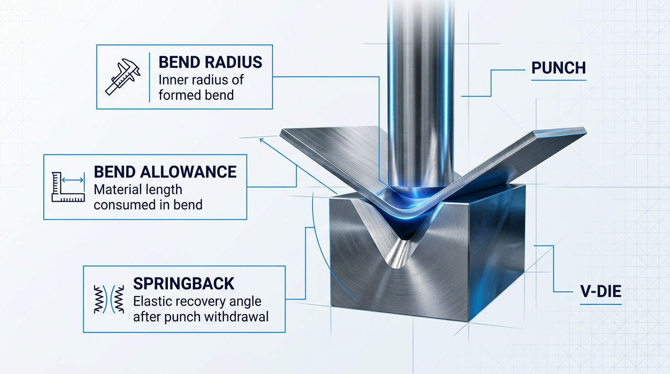
The downstream consequence of press brake precision is concrete: if bend allowance or springback compensation is miscalculated, formed parts will carry dimensional errors into the assembly stage, where mating surfaces will not align and joints will not close correctly.
Springback is not a flaw in the bending process; it is a calculable material behaviour. CNC press brakes compensate for it automatically by overbending to a programmed angle, so the part recovers to the exact specified angle when the punch withdraws.
Roll Forming
Roll forming is a fundamentally different forming method, suited to a different production context. Continuous sheet or strip is fed through a progressive series of roller dies, each of which incrementally bends the material a little further toward the final cross-sectional profile. The material moves continuously through the line, and the finished profile emerges from the far end without interruption.
The process is well suited to constant cross-section profiles: structural channels, angles, tubes, roofing sections, and similar long, uniform shapes. Because the tooling is set up for a single profile and the line runs continuously, roll forming becomes the practical choice for high-volume production of long, uniform shapes where press brake bending would require too many setups, too much handling, and too much time.
Plate Rolling
Plate rolling addresses a different geometric requirement: curving flat plate into cylindrical or conical forms. A set of rolls applies progressive bending force across the width of the plate, drawing it through and curving it along a single axis into the required arc. The result is the curved shell used in pressure vessels, storage tanks, structural cylinders, and large-diameter pipe sections.
It is worth distinguishing plate rolling from roll forming clearly, as the names invite confusion. Roll forming creates a complex cross-sectional profile by progressively bending strip material through multiple roller stations. Plate rolling curves a flat plate into a single-axis arc using a set of bending rolls. The tools, the inputs, and the outputs are all different.
Across all three methods, CNC control is what delivers engineered repeatability. Modern press brakes and roll forming lines read programmed parameters — angles, bend sequences, back-gauge positions, springback compensation values — and execute them consistently across a production run, connecting the dimensional intent of the engineering drawing to the physical geometry of the formed part.
With each part formed to the geometry and dimensional specification the design requires, the fabrication process moves to its next critical stage: bringing those individual parts together into permanent assemblies through welding and joining.
Welding and Joining: Bringing the Assembly Together
Once parts have been cut and formed into their final geometry, the fabrication process reaches its most consequential stage: welding. This is where individual components are permanently and structurally united into a finished assembly, and where the geometry of the entire structure is locked in.
Errors at this stage — poor fit-up, heat-induced distortion, or contamination at the weld joint — become structural problems that cannot easily be corrected downstream. That is why professional fabricators treat welding as a discipline, not just an operation.
Three arc welding processes dominate metal fabrication: MIG (GMAW), TIG (GTAW), and arc/stick (SMAW). Each works differently and suits different applications. Mechanical fastening sits alongside them as a non-welded alternative for specific design requirements.
MIG Welding (GMAW — Gas Metal Arc Welding)
In MIG welding, a continuous solid wire electrode is fed automatically through a welding gun and into the weld pool, where an electric arc melts the wire and fuses it to the base metal. A shielding gas — typically a 75% argon / 25% CO₂ mixture for mild steel — is delivered through the same gun to protect the molten pool from atmospheric contamination.
MIG is the workhorse of production fabrication: it is fast, adaptable to a wide range of steel and aluminium alloys, and can handle material from thin sheet up to substantial plate thicknesses. Its lower skill threshold compared to TIG makes it well-suited to high-volume shop environments where throughput matters.
The trade-off is surface sensitivity. Unlike stick welding, the solid MIG wire does not tolerate rust, paint, mill scale, or oil at the weld point — these contaminants cause porosity and structurally weak joints. Clean base metal is a prerequisite, not a preference.
TIG Welding (GTAW — Gas Tungsten Arc Welding)
TIG welding uses a non-consumable tungsten electrode to create the arc, with filler metal added separately by the welder's other hand as a hand-held rod. An inert shielding gas — most commonly argon, which suits all material types and thicknesses — protects the weld pool and electrode from atmospheric contamination.
The process produces high-quality, precision welds with minimal spatter, no slag, and a small heat-affected zone — often requiring little or no post-weld finishing. The welder controls heat input via a foot pedal or fingertip control, enabling precise puddle management that MIG cannot match.
The cost of that precision is speed and skill: TIG is significantly slower than MIG and demands a higher level of operator expertise. Its natural home is thin materials, non-ferrous metals such as aluminium and titanium, stainless steel, and any application where weld appearance is critical — aerospace components, automotive fabrication, and precision assemblies where weld integrity is non-negotiable.
Arc/Stick Welding (SMAW — Shielded Metal Arc Welding)
Stick welding uses a consumable flux-coated electrode rod struck against the base metal to create an arc. As the rod melts into the weld pool, the flux coating burns off to produce a shielding gas and a protective slag layer — providing its own atmospheric protection without any external gas supply.
That self-contained shielding is what makes stick welding uniquely robust. It requires minimal equipment, works effectively outdoors and in the field, and tolerates dirty or rusty metal far better than MIG. The slag must be chipped away after each pass, and precision is lower than either MIG or TIG, but for site work, structural repair, and maintenance welding, portability outweighs those limitations.
In controlled fabrication shop environments, stick welding is less common than MIG or TIG — its slower deposition rate and the need for frequent electrode changes make it less efficient for production work.
Not every joint in a fabricated assembly needs to be welded. Mechanical fastening — bolting, riveting, and screwed connections — is chosen when the design requires disassembly for maintenance or transport, when dissimilar materials make welding impractical, or when the engineering specification calls for it, as in certain structural connections in construction.
Mechanical joining allows parts to be separated without damage and avoids the thermal distortion that heat input introduces. The trade-off, as TWI notes, is added weight from fasteners and potential stress concentration at drilled holes — factors the design engineer must weigh against the need for disassembly.
According to TWI Global, contaminants including oil, grease, moisture, rust, paint, and zinc coatings at the weld zone cause porosity, wormholes, and lack of fusion — defects that compromise structural integrity. Professional fabrication shops treat pre-weld surface preparation as a process discipline, not a housekeeping step.
The condition of the base metal at the joint governs everything that follows. Regardless of which welding process is used, pre-weld surface preparation is a non-negotiable quality gate: contaminated surfaces produce defective welds that no amount of downstream correction can fully remedy.
With the assembly welded together, attention turns to the surface of the finished fabrication — where surface finishing processes determine its long-term performance, corrosion resistance, and appearance.
Surface Finishing: Protecting and Completing the Fabrication
Every hour of precision cutting, every carefully formed bend, every qualified weld — all of it is at risk if the surface finishing stage is treated as an afterthought. Surface finishing is the stage that determines whether a fabricated part actually survives in service: its corrosion resistance, coating durability, and long-term service life are all decided here.
Before any coating is applied, the surface must be thoroughly prepared. Mill scale — the iron oxide layer that forms on steel during hot rolling — along with weld discolouration, oxides, rust, and grease must be removed completely.
The reason is straightforward: a coating applied over contaminated steel cannot bond properly to the substrate, and premature coating failure is the inevitable result.
ISO 12944-4 is the governing international standard for surface preparation grades on steel structures, defining the cleanliness levels that professional fabricators work to — Sa grades for blast cleaning and St grades for hand and power tool cleaning — and setting the benchmark for coating system design.
Principal Finishing Methods
Liquid paint and primer systems remain the most widely used finishing approach across construction, infrastructure, and general fabrication. Adhesion depends on both surface cleanliness and surface profile — a roughened substrate provides the mechanical key that allows paint to grip — so primer coats are applied first to deliver corrosion inhibition, with topcoats following to provide appearance and UV resistance.
Powder coating is a dry finishing process in which electrostatically charged powder particles are applied to the prepared metal surface and then cured in an oven, where the powder melts and flows into a hard, continuous film. According to the Powder Coating Institute, powder coated products are more resistant to impact, moisture, chipping, UV degradation, and other wear than liquid paint finishes — making it a preferred choice across both industrial and consumer fabricated products.
Hot-dip galvanising takes a different approach: the fabricated steel article is immersed in a bath of molten zinc, which reacts metallurgically with the steel surface to form a series of zinc-iron alloy layers topped by a pure zinc outer layer. The protection is sacrificial in nature — the zinc corrodes preferentially, shielding the steel beneath even where the coating is scratched or damaged — making it the preferred finish for structural steel, infrastructure, and outdoor applications where long service life in corrosive environments is required. BS EN ISO 1461 is the governing standard for hot-dip galvanised coatings on fabricated iron and steel articles.
The quality of surface preparation directly determines the quality of the coating bond. A coating applied over contaminated steel will fail regardless of how well the coating itself is formulated or applied.
Modern fabrication is moving steadily away from traditional wet chemistry approaches to surface preparation. Methods such as acid pickling and solvent degreasing generate hazardous waste streams and face tightening environmental regulation — the US EPA has identified hydrochloric acid emissions from steel pickling facilities as a significant source of toxic air pollutants, and equivalent regulatory pressure applies across European markets.
The industrial shift is toward dry, chemical-free preparation methods that eliminate chemical handling, waste disposal, and the operational downtime that wet chemistry demands.
- Mechanical abrasion: Shot blasting and grinding physically remove mill scale, rust, and oxides while imparting a surface profile that improves coating adhesion.
- Laser-based surface preparation: A focused laser beam ablates mill scale, oxides, and other contamination, stopping at the base material and leaving the substrate intact — no chemicals or abrasives required.
Laser-based surface preparation has gained significant traction in professional fabrication as the capability has matured. Systems such as Woodrow Scientific's ELASER remove mill scale, weld discolouration, oxides, and other surface contamination by laser ablation — the beam stops at the base material, leaving the substrate intact with minimal substrate loss, and the process requires no chemicals, abrasives, or consumables.
With the surface protected and the part structurally complete, the final stage before a fabricated component leaves the workshop is quality inspection — verifying that every dimension, weld, and finish meets the specification it was built to.
Quality Assurance and Tolerances in Fabrication
Once the surface finishing stage is complete, a fabricated part looks finished — but how does a professional fabricator know it is finished to specification? The answer is that quality assurance is not a final checkpoint at the end of the line; it is a discipline woven through every stage of the process, from cutting accuracy and dimensional conformance at forming, through weld integrity and surface condition before coating.
Professional fabrication shops build quality in at every stage rather than inspecting for it at the end — and that distinction separates rigorous, standards-governed fabrication from informal metalwork.
Tolerances: The Language of Acceptable Variation
A tolerance is the total permissible variation in a specified dimension — the difference between the maximum and minimum acceptable limits for a given measurement.
The engineering tension in tolerance specification runs in both directions: tolerances that are too loose risk parts that will not assemble correctly or perform as intended, while tolerances that are unnecessarily tight drive up cost through additional precision machining, higher reject rates, and extended inspection time — without adding functional value.
Because working towards higher accuracies increases costs in terms of money, time, and equipment, dimensions should be permitted to vary within the widest limits for which they can still function properly — a principle that makes tolerance specification an upstream engineering decision, not a downstream concern for the fabrication shop alone.
A tolerance that is too tight adds cost without adding function; one that is too loose produces parts that fail to assemble. Getting the specification right — at the design stage, before any metal is cut — is where quality is truly built in.
The formal system for specifying tolerances on fabrication drawings is GD&T (Geometric Dimensioning and Tolerancing), standardised as ASME Y14.5 in the United States and ISO 1101 internationally.
GD&T goes beyond simple plus/minus size tolerances: it is a precise mathematical language that describes the permissible variation in a feature's form, orientation, location, and profile — covering everything from flatness and straightness to the true position of a hole relative to a datum.
By embedding GD&T symbols in engineering drawings or 3D CAD models, designers give fabricators, production teams, and quality inspectors a common language — eliminating the guesswork that leads to scrap, rework, and assembly failures.
Visual Inspection: The First Line of Quality Control
The most fundamental and widely used inspection method in fabrication is visual inspection — applied before, during, and after welding to detect surface defects, dimensional errors, and weld discontinuities.
Visual inspection is not casual eyeballing: it is a structured, standards-governed activity with defined acceptance criteria, governed by ISO 17637 (visual testing of fusion-welded joints) and AWS B1.11 (guide for the visual examination of welds).
ISO 17637 specifies test conditions — including required illuminance levels and inspection angles — as well as personnel qualification requirements and documentation standards, ensuring that visual testing is uniform and repeatable regardless of the materials or processes involved.
AWS B1.11 organises visual examination into three categories based on timing: prior to welding, during welding, and after welding — reinforcing that quality control is a continuous activity across the weld sequence, not a single post-weld check.
Non-Destructive Testing: Detecting What Eyes Cannot See
Where visual inspection is limited to surface examination, non-destructive testing (NDT) extends quality control into the interior of welds and parent material — detecting sub-surface flaws without damaging or destroying the part.
The four principal NDT methods used in fabrication each address a different class of defect and material type.
- Ultrasonic testing (UT): High-frequency sound waves are transmitted into the material; internal flaws reflect the wave back to a receiver, revealing location and depth of defects including cracks and lack of fusion.
- Magnetic particle inspection (MPI): The component is magnetised; surface and near-surface discontinuities in ferromagnetic (ferritic) steels disrupt the magnetic flux, drawing visible particles to the defect location.
- Dye penetrant testing (DPT): A low-viscosity coloured or fluorescent dye penetrates surface-breaking defects; a developer draws the dye back to the surface, revealing fine cracks and porosity across ferrous and non-ferrous materials.
- Radiographic testing (RT): X-rays or gamma rays pass through the weld; differences in material density and thickness are recorded on film or a digital detector, imaging internal voids, inclusions, and porosity.
The governing framework for NDT in fabrication is provided by ISO 17635 (general rules for NDT of fusion-welded joints, covering method selection and acceptance levels) and ISO 9712 (qualification and certification of NDT personnel), which together ensure that both the methods and the people applying them meet defined competence standards.
As noted by TWI Global, NDT methods can be undertaken during production, post-production, in-service, and following repair — making them a tool for continuous quality management across the full asset lifecycle, not just a one-time post-fabrication check.
Dimensional Inspection and Coordinate Measuring Machines
Dimensional inspection verifies that fabricated parts conform to the geometry specified in engineering drawings — confirming that every hole location, flange angle, and profile dimension falls within the tolerances the designer specified.
The primary metrology tool for complex fabricated assemblies is the Coordinate Measuring Machine (CMM): a system that uses contact probes or laser-scanning sensors to map a part's geometry in three-dimensional space, then compares the measured data directly against the CAD model.
CMMs are particularly valuable for assemblies where manual measurement cannot reliably reach all features — and modern direct computer controlled (DCC) CMMs can execute dimensional analysis, tooling certifications, and full GD&T evaluation automatically, funnelling data back into the production loop for continuous improvement.
Standards and Certification Frameworks
Professional fabrication quality is governed by a set of recognised standards and certification frameworks that give clients and structural specifiers objective confidence in a fabricator's output.
BS EN 1090-2 is the European standard for the execution of steel structures, specifying technical requirements covering materials, welding, surface treatment, geometrical tolerances, and inspection — including CE marking requirements under the Construction Products Regulation.
In the United States, the equivalent benchmark is AISC certification, operated by the American Institute of Steel Construction: a quality management system programme that examines a fabricator's entire operation — personnel, procedures, equipment, and documentation — rather than simply inspecting finished products.
Underpinning both frameworks is ISO 9001, the international standard for quality management systems, which governs how a fabrication shop documents its processes, conducts internal audits, and drives continual improvement across all production activities.
These standards are not bureaucratic overhead: they are the evidence base that distinguishes a fabricator whose quality is systematic and auditable from one whose quality is informal and unverifiable.
Fabrication Methods: Quick-Reference Summary Table
The table below consolidates the principal methods across the four major fabrication process stages covered in this guide, with their primary use cases and key practical considerations.
| Process Stage | Method | Primary Use Case | Key Considerations |
|---|---|---|---|
| Cutting | Laser cutting | Precision profiling of sheet and plate; complex 2D geometries | Very tight tolerances (±0.1 mm typical); minimal heat-affected zone; best for thinner material |
| Cutting | Plasma cutting | Cutting thicker steel and conductive metals at speed | Wider heat-affected zone than laser; faster on thick plate; lower edge quality than laser |
| Cutting | Waterjet cutting | Heat-sensitive materials; thick plate; no HAZ required | No heat-affected zone; slower than laser/plasma; suits aluminium, hardened steel, composites |
| Cutting | Shearing | Straight-line cuts on flat sheet stock | Fast and low-cost for simple cuts; limited to straight lines; no complex profiles |
| Forming | Press brake bending | Forming sheet and plate into angles, channels, and enclosures | Springback must be compensated; bend radius depends on material thickness and tensile strength |
| Forming | Roll forming | Continuous curved profiles; cylindrical and conical sections | Suited to long runs; consistent cross-section; material must have adequate ductility |
| Forming | Punching / stamping | High-volume production of holes, slots, and formed features | Fast for repetitive features; tooling cost is upfront; consistent repeatability at volume |
| Welding / Joining | MIG welding (GMAW) | General structural fabrication; medium to thick steel and aluminium | High deposition rate; suited to production environments; requires shielding gas |
| Welding / Joining | TIG welding (GTAW) | Precision welds on thin material; stainless steel and aluminium | Slow but highest quality; minimal spatter; requires skilled operator |
| Welding / Joining | Stick welding (SMAW) | Site work and heavy structural steel; outdoor and positional welding | Versatile and portable; tolerates surface contamination better than MIG/TIG |
| Welding / Joining | Mechanical fastening | Bolted connections; assemblies requiring disassembly or field erection | No heat input; allows for tolerance adjustment on site; relies on joint design and bolt specification |
| Surface Finishing | Powder coating | Decorative and protective finish on structural and architectural steelwork | Requires clean, blast-prepared surface; durable colour finish; not suited to very thick coatings |
| Surface Finishing | Hot-dip galvanising | Long-term corrosion protection for outdoor or buried structural steel | Full immersion process; coating thickness ~85 µm typical; alters final dimensions slightly |
| Surface Finishing | Wet paint / primer systems | Site-applied or complex assemblies; multi-coat corrosion protection systems | Surface preparation is critical; coating performance depends on DFT and application conditions |
| Surface Finishing | Shot blasting | Surface preparation prior to coating; removal of mill scale and rust | Creates anchor profile for coating adhesion; graded to Sa 2.5 or Sa 3 per ISO 8501-1 |
Quick-reference summary of fabrication methods by process stage, use case, and key considerations for the reader to use as a standalone reference after reading the guide.
What the table makes clear is that no single method dominates across all stages: professional fabrication involves selecting and sequencing methods based on material type, geometry, tolerance requirements, and the application environment the finished part will face.
The interdependencies matter as much as the individual method choices — a laser-cut blank with tight tolerances can be compromised by a poorly specified bend allowance, just as a structurally sound weld can fail prematurely if the surface preparation before coating is inadequate.
With the full fabrication process and the quality framework that governs it now established, the next section examines the industries that depend on fabrication to this standard — from construction and infrastructure to aerospace and energy.
Industries That Rely on Metal Fabrication
The fabrication process covered throughout this guide does not exist in isolation — it feeds directly into some of the largest and most consequential industries in the global economy. From the steel skeleton of a high-rise to the pressure hull of an aerospace component, fabricated metalwork is the physical substance of the built world.
Construction and Infrastructure
Construction and infrastructure represent the largest single consumer of structural steel fabrication, and the relationship is foundational in the most literal sense.
The American Institute of Steel Construction (AISC) describes structural steel fabrication as central to the construction of buildings, bridges, stadiums, and civil infrastructure across North America — a sector where fabricated beams, columns, connection plates, and moment frames are engineered to precise specifications in a fabrication shop, then transported and erected on site.
What makes fabrication indispensable here is not just the material itself, but the ability to produce structural assemblies to engineering tolerances that the design demands — components that will bear load, transfer force, and perform predictably for decades.
Structural steel fabrication is not incidental to construction; it is the load-bearing skeleton of the built environment, and the quality of that fabrication is what keeps buildings standing and bridges safe.
Automotive Manufacturing
The automotive industry places fabrication under a different kind of pressure: extreme volume combined with tight dimensional tolerances, where every deviation from specification has direct implications for vehicle safety and performance.
Body structures, chassis components, and powertrain housings are fabricated from advanced high-strength steels (AHSS) and aluminium alloys — the same material families covered in the material selection section of this guide — chosen specifically for their strength-to-weight characteristics and formability.
The precision and repeatability that CAD-driven design and CNC press brake forming deliver are not optional extras in automotive fabrication; they are the mechanism by which a body panel or structural rail can be produced to the same specification across millions of units.
Aerospace
Aerospace represents the most demanding tolerance regime of any fabrication sector — a context where the margin between a compliant part and a rejected one can be measured in fractions of a millimetre, and where failure is not an acceptable outcome.
Materials in aerospace fabrication include titanium, specialist aluminium alloys, and high-performance steels, each selected for specific structural and thermal performance requirements.
Quality management in aerospace fabrication is governed by AS9100, the internationally recognised quality management standard specific to the aviation, space, and defence industries, which imposes documentation, traceability, and process control requirements that go well beyond general manufacturing standards.
Cutting method selection in aerospace is particularly consequential: the heat-affected zone (HAZ) generated by thermal cutting processes such as laser and plasma cutting can alter the microstructure and reduce the fatigue resistance of safety-critical components, which is why cold-cutting methods and precision machining are frequently preferred for structural aerospace parts — a direct application of the cutting method trade-offs discussed earlier in this guide.
Energy and Infrastructure
Large-scale energy infrastructure depends on structural fabrication in ways that are easy to overlook but impossible to replace.
Wind turbine towers are one of the clearest illustrations: each tower is built from rolled and welded steel cans — cylindrical sections formed using the plate rolling and welding techniques covered earlier in this guide — stacked and joined to reach heights of 80 metres or more.
Pipelines present a different application of the same discipline: fabricated pipe sections, produced to strict dimensional and material specifications, are joined end-to-end to form long-distance infrastructure carrying oil, gas, and water across continents, with the integrity of every weld directly governing the safety of the system.
In both cases, the scale of the fabrication challenge is enormous — not just in the size of individual components, but in the consistency required across thousands of identical assemblies produced for a single project.
Industrial Equipment and Machinery
Industrial equipment and machinery may be the least glamorous fabrication sector, but it is arguably the most pervasive — virtually every piece of manufacturing plant, processing equipment, and heavy machinery contains fabricated metalwork as its physical structure.
Fabricated frames, housings, enclosures, and structural assemblies define the geometry of the equipment, carry the operational loads, and protect the internal components — making the quality of that fabrication a direct determinant of equipment performance, safety, and service life.
This sector operates at enormous aggregate volume, with fabrication shops supplying structural assemblies to machine builders, plant engineers, and processing industries across every corner of the economy.
In every industry that depends on fabrication, the core value is the same: the ability to translate an engineered design into a complex, precise metal assembly — to specification, at scale, and to a documented quality standard. That is what makes fabrication a foundational industrial discipline, not a niche trade.
With the full arc of the fabrication process now mapped — from design and material selection through to the industries that depend on its outputs — the final section draws together what this guide has covered and points toward where to go next.
Conclusion
Understanding Fabrication: What Comes Next
What distinguishes professional fabrication from ad-hoc metalwork is not the presence of the same tools and processes, but the quality of the decisions made at every stage — decisions that compound, for better or worse, all the way to the finished part.
Tolerance control, surface cleanliness, and process discipline are not finishing touches; they are the thread running through the entire discipline, and the standard by which serious fabrication work is ultimately judged.
Frequently Asked Questions About Metal Fabrication
Answers to common questions about what fabricating means, how it differs from manufacturing, which materials are used, and what quality standards apply.
In an industrial context, fabricating means constructing items from raw or semi-finished materials through processes such as cutting, bending, welding, and assembling. This is distinct from the general English meaning of the word — to fabricate can also mean to invent or make something up — but in industry, the term refers specifically to the physical act of construction. The result of fabrication is a finished structure, component part, or assembly that did not previously exist in that form.
To fabricate something, in a manufacturing sense, is to make it from constituent materials using industrial processes — cutting, forming, and joining — so that the result is a finished part or structure ready for assembly or use. The emphasis is on the act of construction: something that did not previously exist as a finished item is built from raw or semi-finished stock. Fabrication services are typically offered by a fabrication shop, working with materials such as mild steel, stainless steel, and aluminium to produce components to a customer's specification.
Manufacturing involves creating a complete product ready for a consumer, using either raw materials or prefabricated parts. Fabrication is the creation of component parts or assemblies that can then be used to make that final item. The two are not mutually exclusive — in modern supply chains they frequently occur together, with fabricated parts flowing into a larger manufacturing or assembly process. A fabrication shop (often called a fab shop) typically works from engineering drawings and specifications, producing parts to order rather than finished consumer products for direct sale.
The most widely used materials are steel (in several forms), aluminium and its alloys, and a range of specialist metals for specific applications. Mild and structural steel — such as grades A36 and S275 — are favoured for their weldability and strength in general fabrication. Stainless steel, particularly grades 304 and 316, is chosen where corrosion resistance is the priority: grade 304 suits general and food-industry use, while grade 316 (with its added molybdenum) is preferred for marine and chemical environments. Aluminium offers a density roughly one-third that of steel, giving it a high strength-to-weight ratio that makes it valuable in transport and aerospace applications. Specialist metals such as titanium — combining high strength, low density, and outstanding corrosion resistance — are used in aerospace, offshore, and high-performance engineering. Copper alloys are selected where electrical or thermal conductivity is the primary requirement. Material selection is always driven by the application's demands for strength, weight, corrosion resistance, and cost.
The principal certification frameworks for fabrication shops are ISO 9001, BS EN 1090-2, and AISC Certification. ISO 9001 is the globally recognised quality management system standard — it governs how a fabrication shop establishes, maintains, and continually improves its processes and quality controls, and has been issued to organisations in over 189 countries. BS EN 1090-2 is the European standard for the execution of steel structures, covering materials, welding, surface treatment, tolerances, inspection, and testing; compliance is required for CE marking of structural steelwork under the Construction Products Regulation. AISC Certification is the equivalent framework in the United States, confirming that a structural steel fabricating facility has the personnel, documented procedures, and quality management system to produce fabricated steel of the required quality. None of these certifications are cosmetic: each requires documented processes, audited conformance, and ongoing surveillance. For welding-intensive shops, ISO 3834 — the quality requirements standard for fusion welding of metallic materials — provides a further, welding-specific layer of quality assurance that complements both ISO 9001 and BS EN 1090-2.
The heat-affected zone (HAZ) is the area of base metal immediately adjacent to a weld or thermal cut that has been altered by the heat of the process. It has not melted, but the thermal cycle changes its microstructure — and with it, potentially, its mechanical properties such as hardness and toughness. In fabrication, a poorly managed HAZ can compromise structural integrity or require post-weld heat treatment to restore material properties. The size of the HAZ varies by process: according to Hypertherm's cutting process comparison data, laser cutting produces the smallest HAZ depths, plasma cutting sits in the middle, and oxyfuel produces the largest — a difference that directly influences cutting method selection. Managing the HAZ is therefore a key consideration in both choosing a cutting method and qualifying a welding procedure.