

Introduction
This guide is written for engineers, researchers, and technically literate buyers who want a genuine conceptual foundation in laser pumping before evaluating systems or making procurement decisions.
By the end, you will understand why pumping is necessary, what methods and devices are available, and what engineering trade-offs govern real-world choices — the kind of understanding that separates a well-specified system from a poorly chosen one.
The guide moves from foundational physics through pumping methods and devices to practical engineering considerations, so you can follow the full arc or navigate directly to the section most relevant to your needs.
TL;DR
Laser pumping is not a single engineering decision — it is a cluster of tightly coupled ones. The pump source, its geometry, its spectral output, and how heat is managed all interact, and a weakness in any one dimension constrains the whole system.
Understanding how these trade-offs connect is what allows you to evaluate architectures with confidence rather than defer to a datasheet.
This article covers:

Optical, electrical, and chemical pumping methods
Flashlamp and diode pump devices compared
End pumping vs. side pumping geometry
Thermal management in pumped laser systems
Spectral matching and pump efficiency metrics
What Are Laser Pumps?
A gain medium left to itself does not amplify light — it absorbs it. At thermal equilibrium, the Boltzmann distribution ensures that the vast majority of atoms sit in lower energy states, so any photon passing through is far more likely to be absorbed than to trigger stimulated emission. The entire function of a laser pump is to break that equilibrium: to deliver enough external energy that the medium flips from absorber to amplifier.
Laser pumping is the process of supplying external energy to a gain medium — the material (solid crystal, glass, gas, or liquid) in which optical amplification occurs — to excite atoms or ions from lower to higher energy states.
The goal of that excitation is population inversion: a condition in which more atoms occupy the upper laser level than the lower laser level, so stimulated emission dominates over absorption and the medium delivers net optical gain. Population inversion is not a design optimisation; it is the physical prerequisite for any laser to function at all.
A critical constraint shapes how this inversion must be achieved. In a hypothetical two-level system, the pump photon drives atoms from the ground state to the upper level — but the same photon, or an identical one from the growing laser field, can drive stimulated emission right back down. The pump and the laser field compete on equal terms, and the best achievable outcome is equal populations in both levels: transparency, not gain. True inversion cannot be sustained in a two-level system under optical pumping, which is why real lasers are built around three or four energy levels.
Three-Level, Four-Level, and Quasi-Three-Level Systems
In a three-level system, the pump excites atoms from the ground state to a third, higher-energy pump band. From there, fast non-radiative (phonon-mediated) decay rapidly transfers atoms down to the upper laser level — fast enough that the pump band stays nearly empty. The laser transition then occurs from the upper laser level back to the ground state. The difficulty is that the lower laser level is the ground state, which is always heavily populated at thermal equilibrium; achieving inversion requires the pump to deplete a significant fraction of the ground-state population, demanding high pump intensity. Ruby (Cr³⁺:Al₂O₃) is the canonical three-level gain medium.
A four-level system resolves this bottleneck by placing the lower laser level above the ground state. The pump excites atoms to a fourth, highest-energy level; fast non-radiative decay populates the upper laser level; the laser transition fires to the lower laser level; and a second fast non-radiative decay rapidly empties that lower level back to the ground state. Because the lower laser level sits above the ground state, it carries negligible thermal population at room temperature and is continuously drained — population inversion is established at much lower pump power than in any three-level scheme. Nd:YAG is the archetypal four-level gain medium and the architecture that underlies the majority of commercial solid-state lasers.
Some commercially important gain media, most notably Yb:YAG and ytterbium-doped fibre, occupy an intermediate position known as quasi-three-level systems: the lower laser level sits close enough to the ground state that it carries non-negligible thermal population at room temperature, requiring meaningful pump intensity to overcome reabsorption — but it is not the ground state itself, so reasonable efficiency remains achievable.
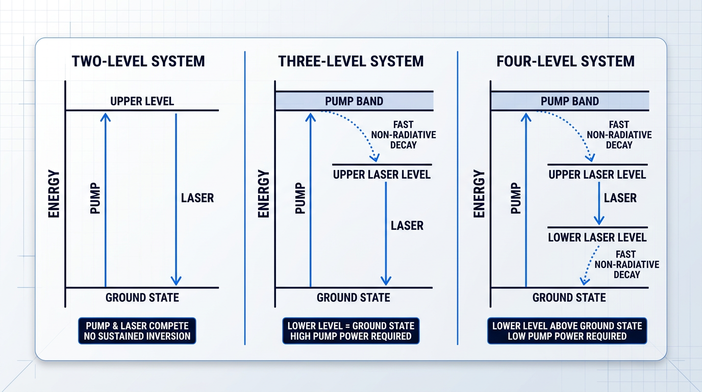
The diagram above makes the practical consequence clear: as the energy-level architecture progresses from two-level through three-level to four-level, the lower laser level becomes progressively easier to keep depopulated, and the pump power required to sustain inversion falls accordingly — which is precisely why four-level systems dominate commercial solid-state laser design.
Every energy-level architecture carries an inherent thermal cost captured by the concept of the quantum defect. Each absorbed pump photon has a shorter wavelength — and therefore higher energy — than each emitted laser photon; the energy difference is shed as heat through the non-radiative decay steps that populate and depopulate the laser levels. This is not a flaw that better engineering can eliminate; it is a thermodynamic consequence of the level structure itself, and it means that even a theoretically perfect laser system converts a fixed fraction of every absorbed pump photon directly into heat in the gain medium. The thermal management implications of the quantum defect are addressed in detail later in this guide.
Every pumped laser system deposits heat in the gain medium as a direct thermodynamic consequence of its energy-level architecture. The quantum defect — the energy gap between absorbed pump photons and emitted laser photons — cannot be engineered away; it can only be managed.
With the energy-level framework in place — why pumping is physically necessary, how three- and four-level systems achieve inversion, and where the quantum defect originates — the next question is how external energy is actually delivered to the gain medium, and that answer varies significantly depending on the type of laser.
Methods of Laser Pumping: Optical, Electrical, and Chemical
The choice of pumping method is not an arbitrary engineering decision — it is determined by the physical properties of the gain medium itself. A gain medium that cannot absorb lamp light efficiently cannot be optically pumped with a lamp; one with no useful optical absorption bandwidth cannot be pumped with light at all. Understanding why each method exists means understanding what the gain medium demands of its energy source.
Optical Pumping
Optical pumping works by directing light from an external source — a lamp or another laser — into the gain medium, where it is absorbed and used to excite atoms or ions from lower to upper energy levels, creating the population inversion required for stimulated emission.
The governing physical constraint is spectral overlap: the emission spectrum of the pump source must coincide with the gain medium's absorption bands for energy transfer to occur at all. This is not a preference that can be engineered around — if the pump photons fall outside the absorption bands, the medium is transparent to them and no excitation takes place.
Solid-state gain media such as Nd:YAG, Yb:YAG, and Er-doped fibre are well suited to optical pumping because their absorption bands are broad enough to capture useful energy from incoherent broadband sources such as arc lamps. Nd:YAG, for example, exhibits strong pump absorption in the 800 nm region, making it amenable to lamp pumping.
Narrowband sources — particularly laser diodes tuned to the absorption peak — are considerably more efficient, because they concentrate their output precisely where the gain medium absorbs most strongly, wasting far less energy as heat via the quantum defect. This efficiency advantage is why diode pumping has progressively displaced lamp pumping across most solid-state laser platforms.
Optical pumping is the dominant method for solid-state and fibre lasers, and it is the foundation on which the remainder of this guide is built — covering the specific devices (flashlamps, laser diodes) and geometries through which pump light is delivered to the gain medium.
Electrical Pumping
For gas lasers, electrical pumping works through a fundamentally different mechanism. An electrical discharge through the gas creates a plasma; energetic free electrons are accelerated by the electric field and collide with gas atoms or molecules, transferring kinetic energy that excites them into upper energy levels. This process — electron-impact excitation — does not involve photon absorption at all.
The CO₂ laser and the helium-neon (HeNe) laser are both canonical examples. In the CO₂ system, the discharge primarily excites nitrogen molecules, which then transfer their excitation energy to CO₂ molecules via collisions, populating the upper laser level. The discharge can be driven by DC, AC, or radio-frequency current depending on the laser configuration.
In semiconductor lasers, electrical pumping takes a different form. An electric current is driven across a p-n junction; electrons and holes recombine in the active region, releasing energy as photons through stimulated emission. Crucially, the p-n junction is the gain medium — pumping and lasing occur within the same structure, making semiconductor lasers uniquely compact.
Electrical pumping suits both gas and semiconductor media because their optical absorption bandwidths are too narrow — or effectively absent — for lamp-based optical pumping to be practical. Electrical excitation is non-resonant: it transfers energy through electron collisions or carrier injection rather than requiring the pump energy to match a specific photon absorption wavelength, sidestepping the spectral overlap constraint entirely.
Chemical Pumping
Chemical pumping is the most specialised of the three methods. Here, the products of an exothermic chemical reaction emerge directly in electronically or vibrationally excited states — the reaction itself deposits energy into the reaction products, establishing population inversion without any external electrical or optical energy source.
The primary examples are the hydrogen fluoride (HF) laser, the deuterium fluoride (DF) laser, and the chemical oxygen iodine laser (COIL). In HF and DF systems, fluorine atoms react with hydrogen or deuterium to produce vibrationally excited HF or DF molecules directly. COIL uses a two-stage process: singlet-delta oxygen, generated by reacting chlorine with hydrogen peroxide, transfers its excitation energy to atomic iodine, which then lases at 1.315 µm.
Chemical pumping can deliver very high continuous-wave output powers — reaching megawatt-class levels — which attracted sustained military and directed-energy research interest from the 1960s onward. The DoD terminated its chemical laser development programmes in 2012, driven by the logistical demands of supplying and handling hazardous reactive chemicals such as fluorine, chlorine, and hydrogen peroxide, as well as the challenge of managing waste streams in operational environments.
Chemical lasers have found only very limited industrial application and remain confined primarily to military and directed-energy research contexts. For the engineering and research audience this guide addresses, chemical pumping completes the landscape but is unlikely to be a practical consideration.
Optical pumping works where absorption bands are broad enough to capture external light; electrical pumping works where they are not; chemical pumping works where the reaction products themselves supply the excitation energy. The method follows from the physics — it cannot be chosen freely.
Taken together, the three methods form a spectrum from broadly applicable to highly specialised: optical pumping dominates commercial solid-state and fibre lasers; electrical pumping is standard for gas and semiconductor lasers; chemical pumping remains confined to military and directed-energy research. The sections that follow narrow the focus accordingly, beginning with the devices that have historically delivered optical pump energy to solid-state gain media.
Flashlamp Pumping: Operating Principles and Limitations
When Theodore Maiman produced the first laser pulse on 16 May 1960, the pump source was a photographer's xenon flashlamp wrapped around a synthetic ruby rod — a choice that defined the dominant architecture for solid-state laser pumping for the following three decades.
The operating principle is straightforward in concept. A gas discharge lamp — filled with xenon or krypton at high pressure — produces intense broadband optical radiation when a high-voltage electrical discharge is passed through it, exciting gas atoms into elevated electronic states from which they rapidly emit light across a broad spectral range spanning the ultraviolet, visible, and near-infrared.
Two variants serve different operating regimes: continuous arc lamps, optimised for steady-state CW operation, and pulsed flashlamps, which deliver intense short bursts of pump light for free-running or Q-switched pulsed lasers.
In both cases, the pump light is directed into the gain medium via a reflective pump cavity — most commonly one with an elliptical cross-section, where the lamp and the laser rod are each positioned at one of the two focal points of the ellipse, so that light emitted from the lamp is geometrically concentrated onto the rod with high collection efficiency.
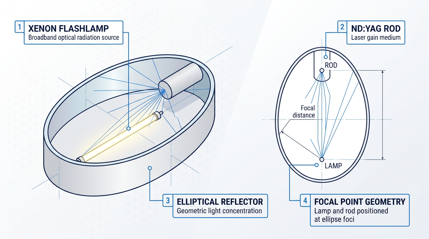
This geometry is effective at collecting and redirecting lamp radiation, but it cannot resolve the more fundamental problem at the heart of flashlamp pumping: the spectral mismatch between what the lamp emits and what the gain medium can actually absorb.
Spectral Mismatch and Thermal Load
A xenon or krypton flashlamp emits a broad, continuous spectrum across hundreds of nanometres, covering the UV, the entire visible range, and into the near-infrared.
Nd:YAG — the most common gain medium in lamp-pumped solid-state lasers — absorbs pump light in a small number of narrow spectral bands, primarily around 808 nm, with secondary bands elsewhere in the near-infrared and visible.
The consequence is that the vast majority of the lamp's optical output falls outside those absorption bands entirely, passing through the gain medium without being absorbed and contributing nothing to the population inversion that drives laser action.
That unabsorbed radiation does not simply disappear — it is converted to heat in the gain medium, the pump cavity walls, and the cooling system, imposing a thermal load on the laser that is large relative to the useful pump power actually delivered to the gain medium.
Compounding this, even the fraction of lamp radiation that is absorbed still generates heat through the quantum defect — as established earlier in this guide, pump photons carry more energy than the laser photons they produce, and the difference is deposited as heat in the crystal lattice regardless of pump source.
In a flashlamp-pumped system, heat arises from two independent sources: the quantum defect (present in any optically pumped laser) and the conversion of non-resonant broadband radiation. Research data indicates that diode pumping produces only around one-third of the heat in an Nd:YAG crystal compared to flashlamp or arc lamp pumping — a direct consequence of eliminating the spectral mismatch component.
The practical result of this elevated thermal load is thermal lensing: non-uniform heating of the gain medium creates a refractive index gradient across the rod's cross-section, causing it to act as a weak lens that distorts the intracavity beam.
Because the pump radiation is spatially incoherent and the heating profile across the rod is inherently non-uniform, the resulting thermal lens introduces aberrations that degrade the resonator mode and make it difficult to achieve diffraction-limited beam quality.
The standard configuration for flashlamp-pumped lasers is a side-pumped rod geometry, where pump light enters the gain medium radially — a geometry that further limits the spatial overlap between the pump volume and the fundamental resonator mode, compounding the beam quality challenge.
For applications where beam quality is a first-order requirement — frequency doubling, precision material processing, interferometry — these limitations have real and consequential effects on system performance, including transient beam hot spots that can damage downstream optics.
Lifetime and Maintenance
Lamp lifetime imposes a recurring operational cost that is worth understanding in concrete terms: continuous arc lamps operated under normal conditions require replacement after only a few hundred hours of operation, while pulsed flashlamps are rated by shot lifetime, typically on the order of 10⁷ shots before the envelope or electrodes degrade to the point of failure.
Each replacement event carries costs beyond the lamp itself — scheduled downtime, reassembly, realignment of the laser cavity, and the risk of catastrophic lamp failure, which can scatter glass fragments through the pump chamber and cooling system.
These are not marginal concerns for an operational system. In high-repetition-rate or continuous industrial applications, lamp replacement cycles translate directly into reduced system availability and increased total cost of ownership.
Where Flashlamps Still Have a Role
A fair engineering assessment of flashlamp pumping must acknowledge that the technology retains genuine advantages in specific contexts, and has not been displaced uniformly across all applications.
- High peak pump power: Flashlamps can deliver very high peak pump powers and pulse energies — reaching hundreds of joules — at a cost per watt far below that of equivalent diode arrays.
- Simple optical arrangement: The elliptical pump cavity is a mature, robust design requiring no beam-combining optics, making lamp-pumped systems straightforward to build and service.
- High-energy pulsed applications: For Q-switched Nd:YAG systems, laser rangefinders, and certain scientific or military pulsed lasers, the capital cost of diode arrays at equivalent pulse energy is often prohibitive.
In practice, high-pulse-energy Nd:YAG systems and certain pulsed dye laser configurations remain the clearest application contexts where flashlamp pumping is the practical choice — not because the limitations are absent, but because the cost of achieving equivalent pulse energy from diode sources is not yet justified at scale.
The limitations described in this section — spectral mismatch, elevated thermal load, restricted beam quality, and finite lamp lifetime — are not failures of a poorly conceived technology; they are the inherent engineering constraints of broadband incoherent pumping applied to spectrally selective gain media. Understanding them precisely is what makes the development of diode pumping legible as an engineering advance rather than a commercial trend. The next section examines how diode pump sources address each of these constraints directly.
Diode Pumping: Spectral Matching, Efficiency, and DPSSLs
The transition from flashlamp to diode pumping was not a matter of incremental refinement — it was a consequence of a single, decisive physical insight: that a pump source whose emission wavelength is precisely matched to the gain medium's absorption peak will always outperform one that is not.
Flashlamps emit across a broad spectral continuum, and only a fraction of that output falls within the narrow absorption bands of most gain media. The rest passes through the crystal as wasted energy, deposited ultimately as heat. Laser diodes, by contrast, emit in a narrow spectral band — and crucially, the emission wavelength can be selected during fabrication to coincide with a specific absorption peak of the target gain medium.
This is spectral matching: the deliberate engineering of pump wavelength to maximise the overlap between diode emission and gain medium absorption. When spectral overlap is high, nearly all incident pump photons are absorbed by the gain medium and contribute to population inversion rather than passing through as unabsorbed radiation.
Two pairings illustrate the principle clearly. GaAs/AlGaAs diodes emit at approximately 808 nm, coinciding with a strong absorption band of the neodymium ion in Nd:YAG — the canonical pairing for solid-state laser pumping, and the one that established diode pumping as a practical architecture. InGaAs diodes, emitting in the 915–976 nm range, are matched to the absorption bands of ytterbium-doped gain media, making them the dominant pump source in modern high-power fibre and disk laser systems.
The efficiency consequence of spectral matching is substantial. As reported in the MIT Lincoln Laboratory journal and corroborated by Stanford research on diode-pumped solid-state lasers, lamp-pumped Nd:YAG systems achieve approximately 1% electrical-to-optical efficiency, while diode-pumped equivalents reach approximately 10% — an order-of-magnitude improvement.
| Parameter | Lamp-Pumped Nd:YAG | Diode-Pumped Nd:YAG |
|---|---|---|
| Electrical-to-optical efficiency | ~1% | ~10% |
| Pump source lifetime (CW operation) | ~200 hours (arc lamp) | typically >10,000 hours |
| Spectral output | Broadband (spectrally unmatched) | Narrow band (spectrally matched to gain medium) |
| Thermal load per watt output | High (most pump energy wasted as heat) | Significantly lower (most pump energy absorbed usefully) |
| Beam quality | Degraded by strong thermal lensing | Improved; end-pumping geometries accessible |
Quantitative comparison of lamp-pumped versus diode-pumped Nd:YAG laser systems across key performance parameters, grounded in MIT Lincoln Laboratory and SPIE source data.
The efficiency gap is not a generic property of diode technology — it is a direct consequence of spectral overlap. In a lamp-pumped system, pulsed flashlamps convert electrical energy to optical energy with reasonable efficiency (30–80%), but because so little of that optical output falls within the gain medium's absorption bands, the lamp-pumped laser as a whole achieves only ~1% wall-plug efficiency. Diode pumping eliminates this spectral waste: the pump photons delivered to the gain medium are the right photons, and nearly all of them are absorbed.
The thermal consequences follow directly. When less pump energy is wasted as heat, the gain medium runs cooler per watt of laser output, reducing cooling system demands and — critically — suppressing thermal lensing, the refractive index gradient that develops across a heated crystal and distorts the laser beam. Thermal lensing is one of the principal beam quality limiters in lamp-pumped systems; diode pumping reduces its severity at the source.
Lifetime is the other dimension where the physics of diode operation delivers a structural advantage. Laser diodes are solid-state devices: there is no gas discharge, no electrode erosion, and no glass envelope to fail. CW arc lamps require replacement after approximately 200–600 hours of continuous operation; diode bars used in laser pumping typically operate for more than 10,000 hours, with manufacturers commonly achieving 20,000–30,000 hours by de-rating operating current below the maximum rated level.
For system designers, this lifetime difference translates directly into maintenance intervals and operational reliability. A lamp-pumped system requires periodic cavity realignment after each lamp change; a diode-pumped system can operate for years without intervention of that kind.
Laser diodes also offer high radiance — optical power per unit area per unit solid angle — relative to the diffuse output of flashlamps. This spatial brightness enables pump light to be focused into the small mode volume of the laser resonator along the beam axis, a geometry known as end pumping. End pumping produces excellent spatial overlap between the pump distribution and the resonator mode, supporting diffraction-limited or near-diffraction-limited output. The trade-offs between end pumping and side pumping, and the engineering considerations that govern geometry selection, are covered in the next section.
Diode pumping does introduce one engineering challenge that requires active management. The emission wavelength of a multimode laser diode is temperature-sensitive, shifting by approximately 0.3 nm per 1 K rise in junction temperature — a figure confirmed by RP Photonics and consistent across multiple sources. For gain media with absorption bands only a few nanometres wide, even modest temperature excursions can meaningfully reduce spectral overlap and erode the efficiency advantage that makes diode pumping attractive in the first place.
The engineering response is junction temperature stabilisation: thermoelectric (Peltier) coolers or water cooling are used to hold the diode at a controlled operating temperature, keeping emission wavelength within the gain medium's absorption band. This adds system complexity, but it is a well-understood and routinely implemented solution. Deeper treatment of wavelength stability methods, including volume Bragg grating locking, is covered in the section on spectral matching and pump efficiency metrics.
Diode-Pumped Solid-State Lasers (DPSSLs)
Diode-pumped solid-state lasers (DPSSLs) are the commercial architecture that the spectral matching advantage made possible. In a DPSSL, laser diodes replace the flashlamps or arc lamps of earlier solid-state systems as the pump source, with the gain medium — typically a doped crystal or glass — excited by spectrally matched diode radiation rather than broadband lamp light.
What the DPSSL architecture delivers is the synthesis of everything covered in this section: high electrical-to-optical efficiency, compact and robust form factor, long operating lifetime measured in tens of thousands of hours, low noise, and access to output wavelengths not directly available from diode lasers themselves — including visible and ultraviolet wavelengths reached via nonlinear frequency conversion of the near-infrared fundamental.
DPSSLs combine spectral precision, low thermal load, and multi-decade operating lifetimes in a single architecture — properties that no lamp-pumped system can match simultaneously. That combination is why they became the standard for demanding solid-state laser applications.
Diode pumping is not simply a historical improvement over flashlamp technology — it is the engineering baseline that well-designed solid-state and fibre laser systems are built around today. The combination of spectral efficiency, controllable thermal load, long operating lifetime, and low noise makes it the rational choice wherever performance and reliability matter.
The high radiance of laser diodes that enables end-pumping geometries is itself a topic with significant engineering depth — the spatial relationship between pump and resonator mode has major consequences for beam quality, output power scaling, and system design, all of which are examined in the next section.
End Pumping vs. Side Pumping: Geometry as a Design Variable
Having established what a pump source is and why its radiance matters, there is a second question that proves equally consequential: where do you put it? The physical arrangement of pump source relative to gain medium — the pumping geometry — determines how well the pump volume overlaps with the resonating laser mode, how thermal load is distributed through the crystal, and how far total pump power can scale. It is not a secondary engineering detail; it is a primary design variable that couples beam quality, thermal management, and power scalability into a single architectural choice.
End Pumping: Spatial Overlap and Its Consequences
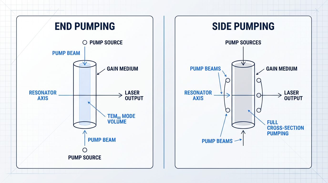
In end pumping (also called longitudinal pumping), the pump beam enters through one or both end faces of the gain medium and propagates along the same axis as the laser beam itself.
This co-propagating geometry is the source of end pumping's defining advantage: spatial overlap between the pump volume and the fundamental resonator mode (TEM₀₀) can be made nearly perfect.
Because the pump beam travels along the resonator axis, it can be focused and shaped to match the transverse intensity profile of the TEM₀₀ mode — which in a typical solid-state resonator may be only tens to a few hundred micrometres in diameter.
When the pump volume is confined within this mode volume, higher-order transverse modes find insufficient gain to reach oscillation threshold; the geometry itself enforces mode selectivity, which is the physical reason end-pumped lasers routinely produce near-diffraction-limited output.
Achieving this tight spatial overlap demands a pump source with high radiance: to focus pump light into a mode volume of this scale, the pump beam must be sufficiently bright that it can be collimated and focused without étendue losses overwhelming the coupling efficiency.
This is precisely why end pumping became practical only with the advent of single-emitter and fibre-coupled diode lasers — and why arc lamps, with their fundamentally low radiance and large emitting area, cannot be used in end-pumped configurations.
The geometry carries two significant liabilities, however, both of which grow more severe as pump power increases.
First, the power-scaling ceiling: pump light can enter from at most two end faces, regardless of how many sources are combined, placing a hard upper bound on total deliverable pump power that makes end pumping unsuitable for very high-power systems.
Second, the thermal gradient problem: absorbed pump power follows Beer-Lambert decay along the propagation axis, so the gain medium is heated most intensely near the input face and progressively less so toward the output end.
This longitudinal temperature gradient produces a thermal lens that varies non-uniformly along the axis — an asymmetric aberration that is considerably harder to compensate than the radially symmetric thermal lensing encountered in side-pumped geometries, and one that becomes a serious engineering constraint at elevated pump powers.
Side Pumping: Power Scalability and Its Trade-offs
In side pumping (transverse pumping), pump light enters perpendicular to the laser beam axis through the lateral surface of the gain medium — typically a rod or slab geometry.
The immediate consequence is a dramatic improvement in power scalability: diode bars, diode arrays, or lamp arrays can be distributed around the full circumference of the gain medium, delivering pump power from many directions simultaneously and allowing total pump power to reach levels that are simply inaccessible to end-pumped architectures.
This makes side pumping the geometry of choice for high-power rod and slab lasers where kilowatt-class output is the target.
The spatial overlap trade-off, however, is significant: because the pump volume spans the entire cross-section of the gain medium — including peripheral regions that lie outside the fundamental resonator mode — gain exists where the resonating beam has little or no intensity.
This poor overlap between pump volume and mode volume reduces extraction efficiency (energy deposited at the periphery is not efficiently harvested by the resonating beam) and simultaneously provides gain for higher-order transverse modes, degrading beam quality relative to end-pumped configurations.
Side-pumped geometries also introduce two coupled thermal engineering challenges.
Non-uniform radial pump absorption creates a radially symmetric refractive index gradient — a thermal lensing effect that, while more predictable in symmetry than the longitudinal gradient of end pumping, still requires careful resonator compensation.
In crystalline gain media such as Nd:YAG rods, the same radial temperature distribution induces thermally induced birefringence: the thermal stress field modifies the refractive indices for different polarisation orientations, depolarising the intracavity beam and introducing polarisation-dependent losses that further degrade beam quality.
Compensating for depolarisation typically requires dedicated resonator measures — such as inserting a 90° polarisation rotator between two identical gain sections to cancel the birefringence contribution of each — adding design complexity that end-pumped systems generally avoid.
End Pumping vs. Side Pumping: A Direct Comparison
The table below characterises the two geometries across the axes that matter most to system designers.
| Design Axis | End Pumping | Side Pumping |
|---|---|---|
| Spatial overlap (pump vs. mode) | High: pump volume shaped to match TEM00 mode volume along the resonator axis; overlap can approach unity | Low-to-moderate: pump volume fills full crystal cross-section, including peripheral regions outside the resonator mode |
| Beam quality | Near-diffraction-limited output; mode selectivity enforced geometrically by confining gain within the TEM00 volume | Degraded relative to end pumping; gain in peripheral regions supports higher-order transverse modes at elevated power |
| Power scalability | Hard ceiling set by two end faces; unsuitable for very high-power systems regardless of source count | Effectively unlimited via additional sources around the circumference; kilowatt-class average power achievable |
| Thermal gradient character | Longitudinal (axial): non-uniform along propagation axis, asymmetric aberration, difficult to compensate optically | Radial: approximately symmetric about the rod axis; more predictable in form, but birefringence adds compensation complexity |
| Pump source brightness requirement | High: single-emitter or fibre-coupled diodes required; arc lamps and low-brightness diode bars unsuitable | Moderate: diode bars, diode arrays, or lamp arrays all viable; brightness requirement is significantly relaxed |
| Typical gain media and applications | Nd:YVO4, Nd:YAG (small rods, microchips); scientific DPSSLs, precision instruments, low-to-medium power CW and pulsed lasers | Nd:YAG rods and slabs; industrial high-power CW and Q-switched lasers, material processing systems |
Direct multi-axis comparison of end pumping and side pumping geometries to support engineering design decisions.
The pattern the table reveals is not a hierarchy but a fundamental coupling: end pumping optimises spatial overlap and beam quality at the cost of power scalability, while side pumping inverts that trade-off — scaling power at the cost of spatial overlap and beam quality.
Both geometries coexist in commercial laser design precisely because neither resolves the trade-off; the right choice is always determined by what the application requires the system to deliver.
It is worth noting that the thin-disk laser — a geometry in which the gain medium is reduced to a very thin disk pumped from one face — represents a variant of end pumping engineered specifically to address the longitudinal thermal gradient problem; its engineering treatment belongs to the thermal management discussion that follows later in this guide.
No single pumping geometry simultaneously optimises spatial overlap, beam quality, and power scalability. End pumping and side pumping each sacrifice one to serve the other — which is why both remain in active use across commercial and scientific laser design. The geometry is chosen by the application, not by convention.
Multi-Pump Configurations: Scaling Beyond a Single Source
When the power available from a single pump source is insufficient, the engineering response is to combine multiple sources — but the strategy for doing so depends on the geometry and the physical properties of the sources being combined.
Three principal multiplexing strategies are used, each exploiting a different physical degree of freedom.
- Spatial multiplexing: Multiple pump sources arranged geometrically — around the circumference in side-pumped systems, or from both ends in end-pumped systems — to increase total delivered power.
- Polarisation multiplexing: Two pump beams with orthogonal polarisations combined at a polarising beamsplitter and launched into the same end face, doubling pump power without increasing beam étendue.
- Wavelength multiplexing: Pump beams at two or more wavelengths, both within the gain medium's absorption band, combined via a dichroic element and co-propagated into the gain medium.
Polarisation multiplexing is particularly valuable for end-pumped systems because it preserves the étendue of the combined beam, maintaining the high effective radiance that end pumping requires — something that simple spatial combination of two beams cannot achieve.
Wavelength multiplexing exploits the finite width of the gain medium's absorption band; the specific wavelengths and dichroic combiner design depend on the absorption spectrum of the gain medium, connecting directly to the spectral matching principles addressed later in this guide.
All three strategies apply to both end- and side-pumped architectures, and in practice they are often combined — for example, spatially multiplexed diode bars whose outputs are themselves wavelength-combined before delivery to a side-pumped rod.
The brightness constraint of end pumping — the fact that only high-radiance sources can be focused into the small mode volumes that end-pumped geometries require — ultimately limits how much pump power can be delivered this way, regardless of how cleverly sources are multiplexed; it is precisely this constraint that the double-clad fibre architecture, discussed in the next section, was engineered to overcome.
Fibre Laser Pumping and the Double-Clad Architecture
The core of a single-mode optical fibre is typically only a few micrometres in diameter, with a correspondingly small numerical aperture — and that creates a fundamental incompatibility with high-power diode pump sources. Broad-area diode bars and stacks are inherently low-brightness: their output occupies a large étendue that cannot be focused down to the tiny acceptance cone of a single-mode core. Launching pump light directly into the signal core is simply not feasible at high power. This is the engineering problem the double-clad fibre architecture was designed to solve — and it does so with considerable elegance.
The double-clad structure places a rare-earth-doped single-mode (or few-mode) signal core at the centre, surrounded by a much larger inner cladding — sometimes called the pump cladding — which itself has a higher refractive index than the outermost polymer jacket.
The outer jacket provides the refractive index contrast that confines pump light within the inner cladding, which acts as a large-area, high-numerical-aperture multimode waveguide — accepting pump light from high-power diodes that would otherwise be incompatible with the signal core.
Pump light launched into the inner cladding propagates in many spatial modes, repeatedly passing through the doped core along the fibre length and being gradually absorbed by the rare-earth ions there. The signal light, by contrast, is guided exclusively in the single-mode core, so its beam quality is determined entirely by the core waveguide geometry — completely independent of the pump's spatial characteristics.
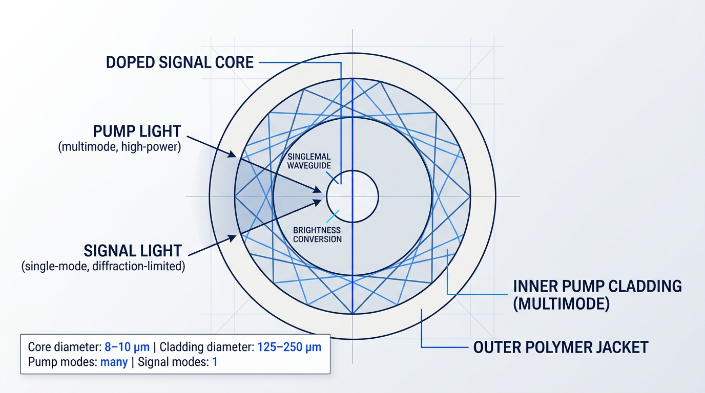
The central physical achievement of this architecture is brightness conversion: low-brightness, high-power pump light carrying many spatial modes is absorbed by the rare-earth ions and re-emitted as signal photons into the single guided mode of the core, producing a diffraction-limited (or near-diffraction-limited) output beam.
The double-clad fibre does not merely guide pump light — it converts low-brightness multimode pump power into a high-brightness, diffraction-limited signal beam. This is what makes high-power, high-beam-quality fibre lasers and amplifiers physically possible.
Pump Absorption Efficiency: What Governs It
How efficiently the inner cladding delivers pump energy to the doped core depends on several interacting engineering variables, the most fundamental being the ratio of inner cladding area to core area: a larger inner cladding relative to the core means each pass of pump light has a lower probability of intersecting the doped region, requiring longer fibre or higher doping concentration to compensate.
Doping concentration and fibre length together set the total available pump absorption — but doping cannot be increased without limit, as excessive concentrations cause quenching effects that degrade gain efficiency.
A subtler but practically important issue is inner cladding geometry. A radially symmetric circular inner cladding allows helical ray paths — sometimes called skew modes — that travel around the core without ever intersecting it, leaving pump power permanently unabsorbed regardless of fibre length.
Breaking the circular symmetry forces mode mixing and eliminates these trapped helical paths. Several geometry variants are used in practice:
- D-shaped cladding: A flat face cut along one side of the circular cladding disrupts symmetry and is among the most widely adopted solutions for improving pump absorption.
- Rectangular cladding: A square or rectangular cross-section breaks radial symmetry entirely, promoting effective mode mixing throughout the pump cladding.
- Offset core: Displacing the doped core from the cladding centre reduces the population of helical modes that avoid the core region.
- Periodically bent fibre: Coiling or otherwise bending the fibre introduces coupling between pump modes, redistributing power into modes with better core overlap.
The choice among these geometries is a practical engineering decision with measurable consequences: a D-shaped or offset-core design can recover a substantial fraction of the pump absorption that a circular symmetric design would leave stranded in poorly-absorbing skew modes.
Pump Coupling Methods
Getting high-power pump light into the inner cladding in the first place requires dedicated coupling hardware. The two principal approaches serve different system architectures.
End-pumping via fibre-coupled pump combiners — also called pump/signal combiners or tapered fibre bundles — is the standard industrial approach. Multiple diode pigtails are arranged around a central signal fibre, fused together, and tapered so that the bundle dimensions match the inner cladding of the active fibre. This allows several pump diodes to be combined into a single pump input at one or both ends of the gain fibre.
Side-pumping techniques, such as embedded-mirror side coupling or V-groove side coupling, launch pump light into the inner cladding through the fibre's side wall rather than its ends — relevant when both fibre ends must remain accessible for signal input and output, or in distributed-pump configurations where pump power needs to be injected at multiple points along the fibre.
Pump Direction in Fibre Amplifiers
In a fibre amplifier, the direction in which pump light propagates relative to the signal is not a trivial choice — it has measurable consequences for both noise figure and power conversion efficiency.
- Forward pumping: Pump co-propagates with the signal. Pump is absorbed near the input end where signal is weakest, producing lower noise figure — preferred for low-noise applications.
- Backward pumping: Pump counter-propagates against the signal. Absorbed near the output end where signal power is highest, yielding higher power conversion efficiency — preferred for high-power amplification.
- Bidirectional pumping: Pump launched from both ends simultaneously. Allows optimisation of both noise figure and efficiency, at the cost of greater system complexity.
For quasi-three-level systems like erbium-doped fibre, forward pumping produces lower amplified spontaneous emission (ASE) noise co-propagating with the signal — even if backward pumping achieves marginally higher total power efficiency — making pump direction a first-order design choice rather than an afterthought.
Erbium-Doped Fibre: The Worked Example
Erbium-doped fibre (EDF) is the canonical gain medium for illustrating the double-clad architecture in practice. Er³⁺ ions absorb pump light at two principal wavelengths: 980 nm, which offers a strong, narrow absorption band and the highest gain efficiency with the lowest noise figure; and around 1480 nm, a weaker but broader in-band transition used where power efficiency takes priority over noise performance.
The amplified signal emerges in the C-band (1530–1565 nm) and L-band (1565–1625 nm) — the 1.5 µm window that underpins long-haul optical communications and, increasingly, a broad range of photonics applications.
The 1550 nm operating window carries a practical advantage beyond the erbium physics: light at wavelengths beyond approximately 1.4 µm is strongly absorbed by the cornea and lens of the eye and cannot reach the retina, giving erbium-fibre systems a higher eye-damage threshold than 1064 nm sources — not absolute safety, but a meaningfully reduced hazard that matters in applications such as LiDAR, free-space optical communications (FSOC), and defence.
Ytterbium-doped fibre (Yb-fibre), pumped at 915–976 nm, achieves optical-to-optical efficiencies above 80% — among the highest of any rare-earth gain medium — because the quantum defect between pump and signal photons is exceptionally small. This makes Yb-fibre the workhorse of multi-kilowatt industrial fibre lasers for cutting and welding, trading the 1550 nm eye-safety and atmospheric transmission advantages for higher efficiency and greater achievable average power at 1064–1080 nm.
A concrete illustration of what the double-clad MOPA architecture makes possible at the demanding end of the application space is Woodrow Scientific's Custom EDFA — an erbium-doped fibre amplifier engineered end-to-end to application requirements, operating across the full 1530–1625 nm window with pump sources matched to the Er absorption bands, and configured per project across output power, pulse regime, cooling, and form factor up to the leading commercially available power levels for erbium fibre.
The fibre architecture also carries a structural thermal advantage: heat generated by the quantum defect is distributed across metres of gain fibre rather than concentrated in a small crystal volume, which reduces peak thermal loading at moderate powers. At very high output powers, however, thermal effects in fibres are not negligible — and managing them across all pumped laser architectures is the subject of the next section.
Thermal Management in Pumped Laser Systems
Heat is not a symptom of a poorly designed laser pump system — it is an unavoidable consequence of the pumping process itself. The real engineering question is whether the architecture has been built to handle it from the start, or whether thermal effects will impose a ceiling on performance that no amount of later adjustment can lift.
The quantum defect, introduced earlier in this guide, is the primary driver: every pump photon absorbed carries more energy than the laser photon subsequently emitted, and that energy difference is deposited directly into the gain medium as heat. At modest pump powers the absolute thermal load is manageable, but the relationship is linear — double the pump power and the heat deposited doubles with it. In multi-watt or kilowatt-class systems, even a gain medium with a relatively small fractional quantum defect is dissipating a substantial thermal power that must go somewhere.
Several additional heat sources compound the quantum defect floor. Non-radiative decay occurs when excited ions relax to lower energy states without emitting a photon, converting stored energy directly to lattice vibrations. Parasitic absorption in the host material — by impurities or by the host lattice itself rather than the active dopant ions — adds a heat load that scales with pump intensity. And pump light that traverses the gain medium without being absorbed is eventually lost elsewhere in the cavity as heat. Together, these secondary sources mean the total thermal load in a real system routinely exceeds what the quantum defect alone would predict.
Thermal Lensing: How Heat Distorts the Beam
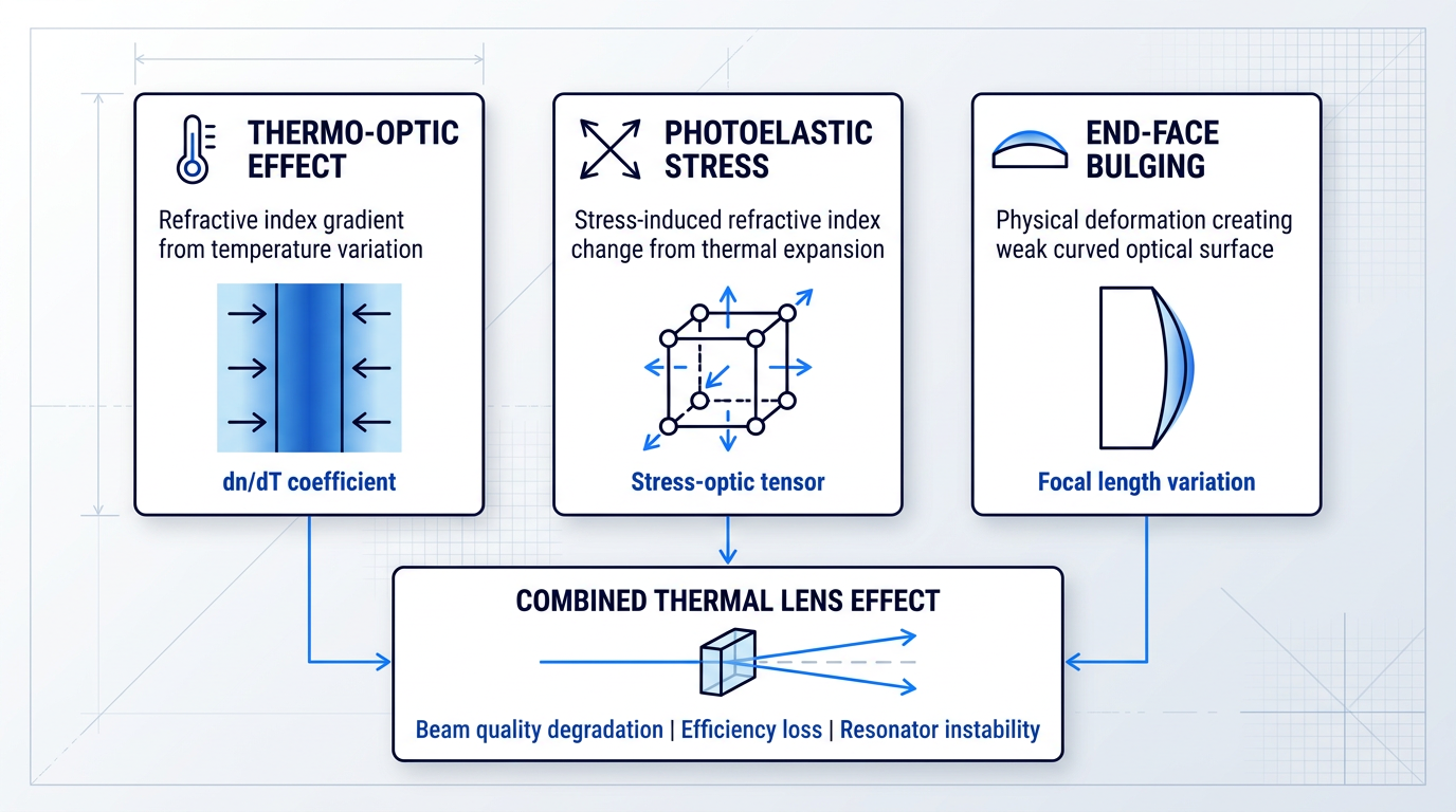
When heat deposition is inhomogeneous — stronger at the centre of the gain medium than at its edges, or stronger near the pump input face than deeper in the crystal — the result is a temperature gradient, and that gradient has three distinct optical consequences. First, the thermo-optic effect (characterised by the material's dn/dT coefficient) means that regions at higher temperature have a different refractive index than cooler surrounding regions, creating a refractive index gradient that bends the propagating beam. Second, the photoelastic effect couples thermally induced mechanical stress back into the refractive index: differential thermal expansion sets up strain fields in the crystal, and those strain fields modify the local refractive index through the stress-optic tensor. Third, physical deformation of the crystal's end faces — end-face bulging caused by differential thermal expansion — acts as a weak curved surface that further deflects the beam.
All three mechanisms act in concert to produce what is collectively called the thermal lens: a spatially varying phase shift imposed on the beam as it propagates through the gain medium. A perfectly uniform temperature distribution would produce no lensing whatsoever; it is the inhomogeneity of heating that is the root cause, not the absolute temperature.
The consequences scale with pump power and compound one another. Beam quality degrades as the beam profile deviates from the ideal Gaussian or near-Gaussian shape that high-performance applications require. Power conversion efficiency falls because the resonator mode is no longer well-matched to the gain volume — the beam samples regions of the gain medium inefficiently. The resonator itself can be pushed toward instability: the thermal lens has an effective focal length that varies with pump power, and as pump power rises, the resonator may approach or cross the boundary of its stability zone. In severe cases, the system exhibits alignment sensitivity and multistable behaviour that makes reliable operation difficult.
End-pumped geometries, as discussed in the geometry section of this guide, are particularly susceptible to this problem. Because pump absorption is concentrated near the input face of the gain medium, the thermal gradient is strongest precisely where the beam enters — producing a spatially non-uniform lens with significant higher-order aberrations beyond a simple focusing term. These higher-order components are substantially harder to compensate optically than the more radially symmetric, lower-order lensing that side-pumped geometries tend to produce. This is the thermal constraint that limits power scaling in end-pumped architectures, even though end-pumping delivers superior beam quality at moderate power levels.
Engineering Responses to Thermal Load
Thermal management in laser pump systems is most effective when it is treated as a design constraint from the outset, shaping the choice of gain medium, pump geometry, and cooling architecture together — not applied as a corrective measure after those choices have been locked in.
- Gain Medium Selection: Materials with low quantum defect, high thermal conductivity, and favourable thermo-optic coefficients generate less heat and extract it faster. Ytterbium-doped media offer a smaller quantum defect than neodymium-doped equivalents at appropriate pump wavelengths.
- Thin-Disk Geometry: Heat is removed longitudinally through the disk's back face, mounted on a heat sink. The thin geometry minimises transverse temperature gradients — the primary cause of thermal lensing — enabling power scaling with weak lensing.
- Cryogenic Cooling: Cooling the gain medium to cryogenic temperatures substantially improves thermal conductivity and reduces thermo-optic coefficients, dramatically lowering thermal lensing. Used in research and high-performance systems where cryogenic operation is practical.
- Composite Laser Crystals: Undoped end caps or cladding bonded to the doped gain crystal spread heat deposition more gradually, reducing peak temperature gradients at the pump input face — most effective in end-pumped configurations.
- Pump Beam Shaping: Optimising the spatial profile of the pump beam produces more uniform absorption across the gain medium, directly reducing the inhomogeneity of heating and the severity of the resulting thermal lens.
Of these approaches, the thin-disk laser is the most architecturally consequential: it is not a thermal mitigation technique added to an existing design, but a geometry conceived specifically around the problem of heat removal. By making the gain medium thin enough that the dominant temperature gradient runs along the beam axis rather than across it, the thin-disk architecture decouples power scaling from thermal lensing in a way that radially cooled bulk crystals cannot achieve — at the cost of a more complex multi-pass pump arrangement to ensure sufficient absorption in the thin gain volume.
Fibre laser architectures enjoy a structural thermal advantage that flows directly from the geometry described in the previous section. Heat generated in a fibre gain medium is distributed over the full length of the fibre — typically several metres — rather than concentrated in a bulk crystal of a few centimetres. This reduces the peak thermal load per unit length by orders of magnitude compared to a bulk solid-state gain medium at equivalent output power, and it is the principal reason fibre lasers can reach high average output powers while maintaining excellent beam quality. Thermal lensing in fibres only becomes significant at very high average powers, where even the distributed heat load accumulates to a level that the fibre geometry can no longer absorb without consequence.
The gain medium, pump geometry, and cooling approach are thermally coupled from the first design decision. Selecting them sequentially — with thermal management as an afterthought — is the most reliable way to build in a performance ceiling that cannot later be engineered away.
Managing the thermal environment of the gain medium, however, addresses only one side of the thermal picture. The pump source itself — particularly diode lasers operating at high drive currents — is also temperature-sensitive, and shifts in junction temperature cause measurable drift in emission wavelength. That wavelength drift, and its interaction with the gain medium's absorption spectrum, is the subject the next section takes up: spectral matching, wavelength stability, and the efficiency metrics that tie them together.
Spectral Matching, Wavelength Stability, and Pump Efficiency
A pumping architecture that looks sound on paper can still deliver poor real-world performance if two disciplines are not applied with rigour: ensuring the pump source emission wavelength is precisely matched to the gain medium's absorption band, and then quantifying how well the entire system converts electrical input into useful laser output. These are the engineering disciplines that separate a well-specified laser pump from one that merely functions.
Spectral Matching and Wavelength Stability
Spectral matching is the requirement that the pump source emission wavelength falls within — and ideally at or near the peak of — the gain medium's absorption band, maximising the fraction of pump photons converted to upper-state population and sustaining population inversion.
Pump absorption efficiency is governed by the gain medium's absorption cross-section, which varies continuously with wavelength: a pump wavelength even a few nanometres off the absorption peak can significantly reduce the absorbed pump fraction. The designer's levers for compensating a suboptimal wavelength overlap are doping concentration and gain medium length — higher doping or a longer gain medium increases total absorption, but neither substitutes for correct spectral alignment.
The complication in real systems is that pump diode emission wavelength is not fixed. Diode laser emission wavelength shifts with junction temperature, at a rate of approximately 0.3 nm per 1 K temperature rise for multimode laser diodes — a figure confirmed by both RP Photonics and NIST characterisation data. At high drive currents, self-heating compounds this wavelength drift further.
The practical consequence depends entirely on the gain medium. For materials with absorption bands several nanometres wide, modest drift is tolerable. For alkali vapour lasers used in diode-pumped alkali laser (DPAL) systems, the absorption bandwidth is approximately 0.01 nm in natural linewidth conditions — broadened to around 0.1 nm with buffer gas — while commercial diode stacks typically emit with spectral widths on the order of 1000 GHz, requiring narrowing by roughly two orders of magnitude to achieve useful overlap.
The standard engineering response to junction temperature drift is active thermal stabilisation: thermoelectric coolers (Peltier elements) for lower-power applications, and water cooling for high-power diode bars and stacks. As established in the thermal management discussion earlier in this guide, the system-level cooling architecture directly determines whether the diode junction temperature — and therefore emission wavelength — can be held within the required tolerance.
A complementary approach is volume Bragg grating (VBG) wavelength locking. A VBG placed after the collimating optic provides narrowband optical feedback that forces the diode to emit within a spectrally narrow window largely independent of temperature drift, reducing emission bandwidth from several nanometres to a small fraction of a nanometre. SPIE proceedings data confirm stabilisation of 0.3 nm FWHM emission bandwidth and wavelength stability of 0.07 nm/°C in VBG-locked pump sources — figures that are critical for gain media such as Yb:YAG in thin-disc configurations, where efficient pump absorption requires tight spectral overlap with the zero-phonon line at 969 nm.
For alkali vapour lasers, the natural absorption linewidth is approximately 0.01 nm — meaning a diode drift of just a fraction of a kelvin's worth of temperature change can push the pump entirely outside the usable absorption window. In such systems, spectral matching is not a tuning preference; it is a hard prerequisite for any lasing action at all.
Pump Efficiency Metrics
Three standard metrics form the quantitative toolkit for evaluating how well a diode-pumped laser system is performing. Each reveals something distinct about a different layer of the system, and read together they form a diagnostic chain from resonator quality through to real-world operating cost.
| Metric | What It Measures | What It Is Sensitive To | What a Low Value Diagnoses |
|---|---|---|---|
| Slope efficiency | Increase in laser output power per unit increase in pump power above threshold | Round-trip resonator loss and gain medium quality | Excessive resonator loss, poor gain medium quality, or suboptimal mode overlap |
| Optical-to-optical efficiency | Ratio of laser output power to absorbed (or incident) pump power | Spectral overlap between pump and gain medium; pump coupling losses | Poor spectral matching, insufficient pump absorption, or high coupling loss |
| Wall-plug efficiency | Ratio of laser output power to total electrical input power for the entire system | Pump source electrical-to-optical conversion, cooling power overhead, all optical losses | Electrically inefficient pump source, excessive cooling load, or cumulative optical losses |
Comparison of the three standard pump efficiency metrics by what each measures, what it is sensitive to, and what a low value diagnoses
The three metrics form an interpretive chain: slope efficiency diagnoses the resonator and gain medium; optical-to-optical efficiency reveals how well spectral matching is working — poor absorption cross-section overlap directly reduces the absorbed pump fraction and therefore this metric; wall-plug efficiency determines whether the whole system is practically viable, capturing losses that the other two metrics do not see. A system can achieve excellent optical-to-optical efficiency yet still deliver poor wall-plug efficiency if the pump diodes themselves are electrically inefficient or the cooling infrastructure consumes substantial power — a distinction that matters acutely for system designers evaluating operating cost and cooling infrastructure requirements.
One design strategy that improves both optical-to-optical and wall-plug efficiency simultaneously is in-band pumping — pumping directly to the upper laser level rather than to a higher-lying pump band. By minimising the quantum defect (the energy difference between absorbed pump photon and emitted laser photon, established earlier in this guide), in-band pumping reduces heat generated per unit of output power, easing the thermal management burden discussed in §9 and raising the fraction of pump energy that emerges as useful laser output.
With spectral matching, wavelength stability, and the three efficiency metrics now in hand, the remaining task is to bring all of these considerations together into a coherent framework for choosing a pumping architecture — which is precisely where the conclusion turns next.
Conclusion
Choosing the Right Pumping Architecture
There is no universally correct pumping architecture — only the one that fits what the system actually needs to deliver.
The variables this guide covered are not independent dials: spectral matching, geometry, thermal management, and efficiency interact, and a decision made in one dimension always shapes the others.
That coupling is the lens worth carrying forward — it is what separates a considered architecture from a collection of individually optimised parts.
Frequently Asked Questions About Laser Pumping
Direct answers to the most common questions about laser pumping methods, devices, and efficiency.
A laser pump delivers external energy to the gain medium, exciting atoms or ions from lower to higher energy states to create the population inversion required for stimulated emission and optical amplification. Without pumping, a laser cannot produce gain — the gain medium simply absorbs incident light rather than amplifying it.
There are three principal methods: optical pumping (using light from a lamp or laser diode), electrical pumping (using electrical discharge or current injection, as in gas and semiconductor lasers), and chemical pumping (using energy released by an exothermic chemical reaction). Within optical pumping, flashlamp and diode pumping are the two main device categories — differing significantly in spectral efficiency, lifetime, and application suitability.
Common pump sources — the physical devices that deliver energy — include flashlamps (arc lamps for continuous-wave operation, pulsed flashlamps for high-energy pulses), laser diodes (now the dominant source for solid-state and fibre lasers), and electrical discharge systems (for gas lasers such as CO₂ and excimer types). Chemical lasers draw their pump energy from the products of an exothermic chemical reaction rather than from a conventional pump device.
A gain medium can only absorb pump light at wavelengths falling within its absorption bands — pump light outside those bands passes straight through without contributing to population inversion. Maximising spectral overlap, ideally at or near the absorption peak, is therefore essential for high pump absorption efficiency and for minimising the thermal load deposited in the medium. This is a principal reason why laser diodes — whose emission wavelength can be tuned to match the absorption peak precisely — displaced flashlamps as the dominant pump source for solid-state lasers.
In end pumping, pump light travels along the laser beam axis, achieving excellent spatial overlap with the resonator mode — this supports high beam quality and high extraction efficiency, but total pump power is limited because light can only enter from the ends of the gain medium. In side pumping, pump light enters perpendicular to the beam axis, allowing multiple pump sources to be arranged around the gain medium for much higher total power — typically at the cost of beam quality and extraction efficiency. End pumping suits high-quality, low-to-medium power systems; side pumping is the preferred route for high-power scaling.
A double-clad fibre consists of a rare-earth-doped signal core — single-mode or few-mode — surrounded by a much larger inner cladding with a higher numerical aperture. High-power pump light from multimode diodes is launched into this inner cladding, where it propagates along the fibre and is gradually absorbed by the doped core. This arrangement allows high-power, low-brightness pump sources to be used whilst maintaining a high-brightness, diffraction-limited signal beam. That combination is the key architectural enabler of high-power fibre lasers and amplifiers, making them highly efficient at power levels that would be impractical with single-mode pump coupling alone.
Wall-plug efficiency is the ratio of laser output power to the total electrical power drawn from the mains supply — making it the most practically relevant efficiency metric for system designers. Unlike optical-to-optical efficiency, which measures only the conversion of pump light to laser output, wall-plug efficiency captures every loss in the chain: pump source conversion efficiency, driver electronics overhead, and thermal management power consumption. It directly determines operating cost and cooling infrastructure requirements. A system that looks impressive on optical-to-optical efficiency alone can still be costly and thermally demanding to run — wall-plug efficiency is what reveals that gap.