

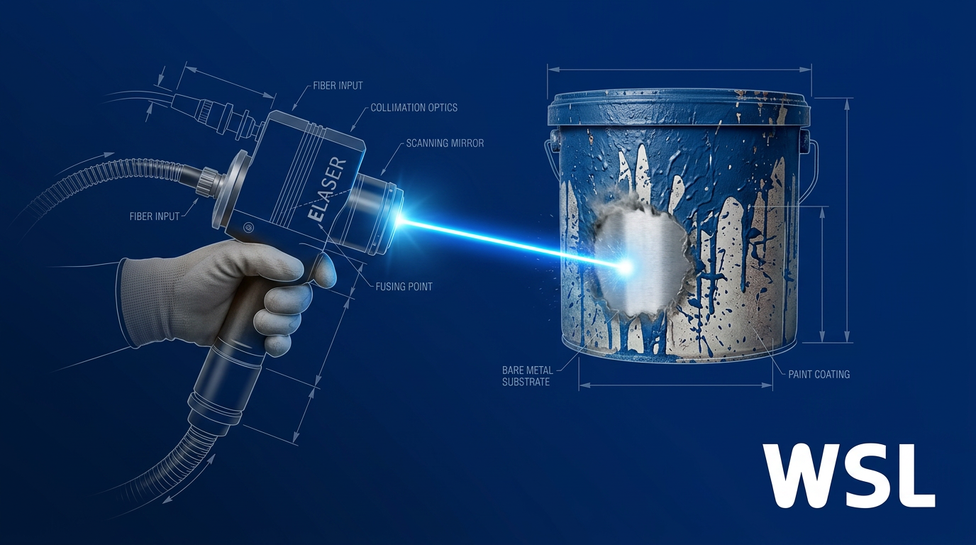
Introduction
This guide is written for operators — people who already have a laser cleaning system, or are close enough to that point that they need to understand the full process before they commit.
If you are still weighing whether to use laser cleaning at all, this is not the right starting point.
By the time you finish, you will be able to run a complete laser paint removal job — from surface assessment through to a clean, inspected result.
That outcome takes more than pointing a beam at a painted surface, and this guide treats it accordingly.
The process framework here applies across the most common real-world scenarios — not every substrate and coating combination, but the complete operational sequence for the jobs you are most likely to face.
TL;DR
Consistent results when you laser remove paint come down to how well you read the job before the beam fires. The machine does not make the decisions — the operator does. This guide walks the complete decision chain, from first assessment to final cleanup, so every pass is deliberate and every result is repeatable.
This article covers:

Assessing substrate, coating, and geometry
Selecting and validating laser parameters
Ventilation, fume extraction, and PPE setup
Running a test pass before full treatment
Executing the cleaning pass with consistent technique
Inspection, cleanup, and job documentation
What You Need to Know Before You Laser Remove Paint
Every time you laser remove paint, three variables determine the outcome: the substrate material, the coating type and thickness, and the machine's power and parameter range.
These variables don't operate independently. The parameters that work perfectly for thin water-based paint on aluminium will be completely wrong for thick industrial epoxy on carbon steel — different ablation threshold, different damage threshold, different pass count.
The operator's job is to read all three before touching the handpiece, then dial in accordingly.
Unlike many industrial processes, laser paint removal has no safe default setting — the correct parameters for one substrate-coating combination can damage a different one at the same power level.
The process has a defined operating window: too little energy leaves coating residue; too much crosses the substrate's damage threshold. Hitting that window consistently — across varying surface conditions, coating thicknesses, and geometries — is what experienced operators do well and first-timers underestimate.
What You Need Before Starting
Before Step 1 is performable, four things must be in hand — missing any one means stopping before you have started.
- Laser cleaning system: A unit with a wide, continuously tunable power range. Fine control across the full power spectrum is non-negotiable for this range of substrates and coatings.
- Fume extraction unit: Dedicated extraction rated for ablation fumes and particulate. Not optional — full setup detail is covered in Step 3.
- Appropriate PPE: Laser safety eyewear rated for your machine's specific wavelength, respiratory protection, and gloves. Step 3 covers selection and fit.
- Scrap test piece: Material identical to your production surface in alloy, surface condition, and coating type. Required for the test pass in Step 4.
On the machine requirement: a system that cannot tune finely across a wide power range forces compromise on every job. Light decorative coatings need low, precise energy delivery; thick powder coatings on steel need sustained higher power. The ELASER covers that full range with 0–100% tunable power up to 300 W and a graphical touchscreen GUI that makes parameter adjustment fast and repeatable.
Pulsed vs. CW: Terminology
Pulsed systems fire discrete bursts of energy; the key parameters are pulse energy (mJ), pulse repetition rate (Hz or kHz), and fluence (J/cm²). CW (continuous wave) systems deliver energy continuously; the key parameters are power (W or % of maximum), scan speed, and scan width.
This guide references both frameworks where relevant. The ELASER operates with an adjustable pulse repetition rate up to 200 kHz and is CW-capable, so if your machine uses fluence terminology, that maps to the energy-per-area concept this guide discusses under power and scan speed settings.
The primary substrates this guide covers are steel (carbon, stainless, and galvanised), aluminium alloys, copper, brass, bronze, titanium, and cast iron — with stone and masonry as additional capable surfaces.
With those prerequisites in hand, the first step is reading the surface itself — because what you find there determines every setting that follows.
Step 1
Assess the Surface

Key Insights
Identify substrate, coating, thickness, and geometry first.
Substrate type sets the ceiling on safe energy.
Clean off oil or grease before starting.
This job brief feeds directly into Step 2.
Before you touch the machine, read the job.
Every parameter decision in Step 2 flows from what you establish here: the substrate material, the coating type, how thick it is, and what the geometry demands.
- Substrate material: Identify the base material: carbon steel, stainless, galvanised steel, aluminium alloy, copper, titanium, stone, or masonry. Each absorbs laser energy differently and has its own damage threshold. The substrate sets the ceiling on how much energy you can safely deliver — get this wrong and you risk marking or warping the base material itself.
- Coating type: Identify what you are removing: water-based paint, solvent-based paint, epoxy, polyurethane, powder coating, primer, lacquer, or graffiti. Each has a different ablation threshold. An epoxy system behaves very differently from a decorative water-based coat. Misidentifying the coating leads to under-powered cleaning or unnecessary risk to the substrate.
- Coating thickness: Judge the thickness band by eye and touch — you do not need a micrometer. A single-layer decorative paint or light lacquer sits at one end; heavy epoxy, primer-plus-topcoat, or a multi-layer industrial system sits at the other. Thick and multi-layer coatings require more passes and more careful heat management than thin single-layer coats.
- Surface geometry: Flat, open surfaces are the baseline case. Flag edges, recesses, complex contours, and thin-section components before you start — each will need technique adjustments during execution. Thin sections accumulate heat faster and are more vulnerable to warping, so identify them now.
- Surface condition: Check for three conditions: corrosion beneath the paint (it changes how the surface responds to laser energy); oil or grease contamination (clean this off before starting — it interferes with ablation and generates additional fumes); and pre-existing substrate damage (damaged areas are more vulnerable to heat effects and need extra care).
When you have worked through all five axes, you have a job brief — mental or written — covering substrate, coating type, approximate thickness, and any geometry or condition flags.
That brief is the direct input to Step 2, where it drives every parameter decision.
Before setting a single parameter, you need four things confirmed: substrate material, coating type, coating thickness, and surface geometry. Any contamination — oil, grease — must be removed from the surface before laser cleaning begins. Everything in Step 2 depends on what you establish here.
Step 2
Select Your Laser Parameters

Key Insights
Fluence governs outcome — stay between thresholds.
Start conservative; validate with a test pass.
With your job brief from Step 1 in hand — substrate material, coating type, approximate thickness, and any geometry flags — you can now translate that assessment into a concrete starting-point parameter set.
For handheld CW systems, the four controls that matter are: power (as a percentage of rated output), scan width, travel speed, and pass count. For pulsed systems, pulse frequency and fluence are the governing terms.
These parameters do not work in isolation — they interact. Together, power, scan width, and travel speed determine how much energy is delivered per unit area of surface. Adjust one and you affect the others.
Fluence — energy density, measured in J/cm² — is the single parameter that ties everything together. Your operating window sits between two thresholds: the coating's ablation threshold (minimum fluence needed to lift it) and the substrate's damage threshold (maximum fluence before micro-melting, discolouration, or hardness change). Too low and the coating stays. Too high and you damage the base material. Every parameter decision is a means of staying inside that window.
Substrate material determines how wide or narrow that window is — and this is where the differences between steel, aluminium, and titanium become consequential.
| Substrate | Operating Window | Damage Onset | Approach |
|---|---|---|---|
| Steel (carbon / alloy) | Wide | ~3–5 J/cm² (nanosecond pulses) | More headroom — start at moderate settings, adjust with confidence |
| Aluminium alloys | Narrower | ~1.5–2.5 J/cm² | More conservative — lower power, wider scan, faster travel |
| Titanium alloys | Narrow, sensitive | Exceeding ~4.44 J/cm² risks surface property changes | Careful fluence control required — small increments only |
Comparing substrate-specific operating windows across the three most common base materials gives the operator an at-a-glance reference for how conservative their starting settings need to be.
With the substrate window in mind, use the coating type to set your starting direction.
- Thin paint or water-based coatings: Medium power, wider scan width, moderate travel speed, 1–3 passes. Lower energy input is usually sufficient and reduces heat risk.
- Thick epoxy or heavy industrial protective coatings: Higher power, narrower scan, slower travel speed, 4–8 passes. Gradual multi-pass removal is safer than attempting aggressive single-pass stripping.
- Multi-layer systems: Work layer by layer. Each layer has its own ablation threshold — do not attempt full-depth removal in a single aggressive pass.
These are starting directions, not fixed prescriptions. The test pass in Step 4 is where you confirm or refine them before any irreversible cleaning begins.
Travel speed is the lever you use to control dwell time. Slower movement delivers more energy per unit area — useful for thick or stubborn coatings, but it raises the heat risk. Faster movement reduces dwell time, which is the right call for thin coatings and heat-sensitive substrates.
New operators often set power and scan width carefully, then move the gun at an inconsistent pace — which is the most common cause of patchy results. Practise a steady, controlled movement on scrap material before working on any production surface.
A machine with a wide, continuously tunable power range is essential for handling the full spectrum of scenarios this guide covers. Fixed or narrow-band power forces compromise — either under-powered for heavy coatings or over-powered for delicate substrates. The ELASER's 0–100% tunable output (up to 300 W) and touchscreen GUI give you direct, precise control over these parameters at the point of use.
Before you move to Step 3, note down your starting parameter set. Know which two failure modes you are steering between.
- Insufficient fluence: Coating remains, streaks appear, surface looks patchy. The job is incomplete. Add passes or increase energy before proceeding.
- Excessive fluence: Substrate discolouration, heat tinting, surface texture change, micro-melting, or warping on thin sections. The substrate has been damaged. Reduce energy immediately.
Recognising these signatures during the test pass is what separates a competent operator from one who discovers the problem too late.
See the Machines Behind the Parameters
You now know what power, frequency, and scan speed need to do. See which laser cleaning machine gives you the control to do it.
Step 3
Set Up Safety and Fume Extraction
Key Insights
Check MSDS before selecting PPE.
Use HEPA plus activated carbon.
Match eyewear OD to wavelength.
With your parameters set, the next task is the workspace itself — and this step is non-negotiable for every operator, regardless of experience level.
Laser paint removal generates smoke, vapour, and fine ablated particulate. Without proper extraction, you face a genuine occupational health hazard — and residue that redeposits on freshly cleaned metal, forcing re-cleaning.
Consult the MSDS First
Pull the Material Safety Data Sheet (MSDS) for the specific coating you are removing before you configure anything else.
Lead-based paints, chromate primers, and epoxy coatings each release distinct byproducts when ablated — the MSDS tells you exactly what filtration specification and respiratory protection your job requires.
Set Up the Extraction Unit
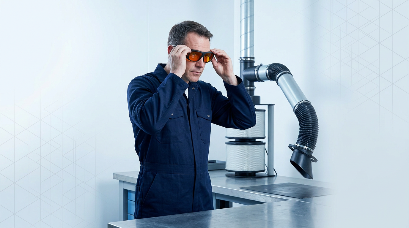
A shop-level extraction unit with three filter stages is the professional standard for sustained coating removal work.
- Pre-filter: Captures coarse particulate before it loads the downstream filters — extends the service life of the HEPA and carbon stages.
- HEPA filter (≥0.3 µm, 99.97% efficiency): The critical stage for fine ablated paint particulate. Particles this size penetrate deep into the lungs — a HEPA-rated filter is the minimum acceptable standard, not a premium option.
- Activated carbon filter: Captures VOCs and chemical fumes released from the paint binder and additives. Particularly important when removing epoxy or solvent-based coatings identified via the MSDS.
Position the extraction nozzle approximately 10–15 cm from the cleaning zone, angled to capture rising fume without crossing the beam path.
For handheld operation, keep the extraction point moving with the cleaning head — source capture at the point of ablation is far more effective than relying on general room ventilation.
A saturated or leaking extraction unit provides no protection. Before activating the laser, confirm the unit is running, the nozzle is drawing correctly, and filters are not at end of service. Turning it on is not the same as verifying it works.
Once extraction is confirmed, don your full PPE set and verify each item before proceeding.
- Laser safety eyewear: Must be rated for your machine's specific output wavelength — check the OD rating and wavelength specification on the lens against the machine's data sheet. General safety glasses are not a substitute.
- Respiratory protection: A NIOSH-approved respirator appropriate to the contaminants identified in the MSDS. The respirator type follows from the coating — do not default to a dust mask.
- Gloves and protective clothing: Protect against UV exposure and spatter. Wear close-fitting, non-reflective clothing that covers exposed skin around the work area.
With PPE confirmed, establish your laser hazard zone. Under ANSI Z136.1 and equivalent standards, conventional Class IV laser cleaning systems require that no unprotected bystanders are present in the area — you are responsible for controlling access before the laser is active.
For operators working in open workshops, mixed-use facilities, or public-facing settings, the ELASER-RHZ from Woodrow Scientific Limited changes this calculus fundamentally.
WSL's world-first reduced hazard zone (RHZ) technology confines the laser hazard to a small area immediately around the work — enabling cleaning to continue without sealing off the space or evacuating bystanders, an operational reality that conventional Class IV systems simply cannot offer.
The ELASER-RHZ is CE and UKCA certified, and WSL provides first-class operator training so every team member working with the system is fully prepared from day one.
Once extraction is running and verified, PPE is donned and checked, and your hazard zone is managed, this step is complete — proceed to Step 4.
Step 4
Run a Test Pass
Key Insights
Scrap first; fallback to non-critical area.
Start low — add energy, never subtract it.
Check for residue, heat marks, texture change.
Multi-layer lifting is expected — add passes.
With your safety setup complete and parameters dialled in, this is the first moment the laser fires on material — and where experienced operators invest a few minutes to protect everything that follows.
A test pass is standard professional discipline, not a beginner precaution. Operators who have run hundreds of jobs still run a test on every new coating and substrate combination, because small differences in surface condition or coating thickness can shift results significantly.
Select your test area. The priority order is clear: identical scrap material is the first choice — same alloy, same surface condition, same coating type and approximate thickness.
If no scrap is available, use a non-visible or non-critical area of the actual part. Never begin on a visible or structurally critical surface.
What looks like the same material can behave differently at the ablation threshold if the coating is slightly thicker, the substrate alloy varies, or the surface has been treated differently.
Set your starting parameters conservatively. Begin at the lower end of the power range for your coating and substrate combination.
For handheld CW systems, that means wider scan width, moderate travel speed, and a lower power percentage. For pulsed systems, start at conservative fluence.
Approach the ablation threshold from below — adding energy is always recoverable; over-exposing the surface on the first pass is not.
Clean a test area of approximately 50 × 50 mm with a single pass at the speed you intend to use on the full job.
Consistent speed is critical: a test pass run too slowly or erratically does not validate the parameters for the actual cleaning pass.
Once the pass is complete, inspect the result against four criteria before making any decisions.
- Coating removal completeness: Is the coating fully ablated, or are there residue patches, streaks, or islands of remaining paint? Incomplete removal tells you what the next adjustment should be.
- Heat marks or discolouration: Check beyond the cleaned zone for tinting, bluing, or any colour change in the substrate. Discolouration outside the treated area indicates thermal input is too high.
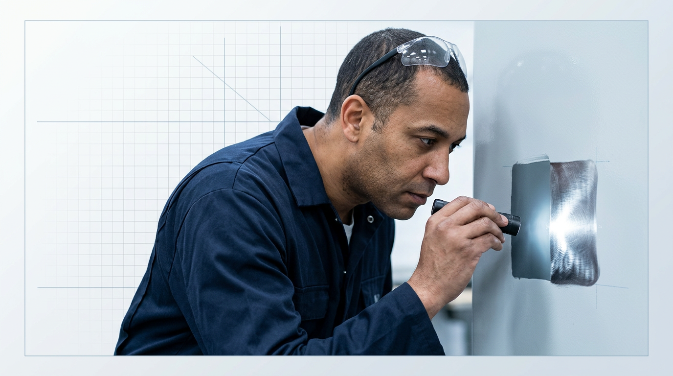
- Surface texture or roughness change: Examine the cleaned substrate under a raking light. Any change in texture or surface finish suggests the beam has interacted with the base material rather than just the coating.
- Warping on thin-section material: On aluminium or thin steel components, check for any distortion along the cleaned edge. Warping is a critical early indicator that heat input needs to be reduced before proceeding.
Based on what the inspection reveals, follow the appropriate adjustment path before committing to the full cleaning pass.
If coating remains after the pass, run another pass at the current settings before reaching for more power. Only increase power if additional passes at the same settings produce no further improvement.
If heat effects are visible — discolouration, tinting, or texture change — reduce power, widen the scan width, or increase travel speed, then re-test. Do not advance to the full cleaning pass until the test result is clean.
On thick or multi-layer paint systems, the first pass often lifts and cracks the coating without fully removing it. This is expected behaviour, not a failure.
Subsequent passes remove the loosened material more cleanly. Multiple passes at moderate power produce better edge quality and safer results than a single aggressive high-power pass.
Once the test produces a consistent, clean result, record the full parameter set: power setting, scan width, approximate travel speed, number of passes, and any job-specific notes. This becomes your reference for Step 5 and cuts test-pass time on every repeat job with the same material and coating.
Step 5
Execute the Cleaning Pass
Key Insights
Inconsistent travel speed causes uneven results.
Use systematic parallel passes with overlap.
Multi-layer jobs: inspect between passes.
Redeposition? Reposition nozzle or reduce power.
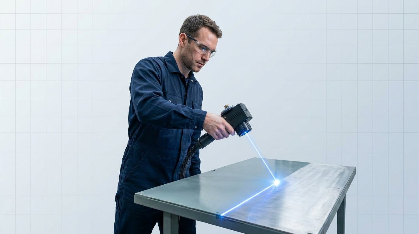
Your parameters are confirmed and recorded from the test pass — now apply them across the full surface.
What separates a clean, consistent result from a patchy one is almost never the machine settings at this point; it is technique discipline during the pass itself.
Travel speed is the primary variable you control in handheld cleaning, and inconsistency is the primary cause of uneven results.
Move too fast and the coating absorbs insufficient energy, leaving residue behind; move too slow and you concentrate energy in one spot, risking localised overexposure of the substrate beneath.
Develop a deliberate, metronomic movement rhythm before you begin and hold it throughout — this is a physical skill, not a parameter you can dial in.
Working distance is the second critical variable and demands the same active attention as speed.
The cleaning head's focal point is calibrated for a specific standoff from the surface: drift too close and the spot tightens, increasing fluence and risking substrate damage; drift too far and effective fluence drops, leaving residue just as surely as moving too fast.
Keep your grip consistent and let your arm drive the movement — not your wrist — so standoff stays stable across the full pass.
Beyond speed and distance, the pattern you work in determines whether you cover the entire area uniformly.
- Work in parallel passes: Use a raster or zigzag pattern across the surface — parallel scan lines traversed in sequence. This is the only approach that guarantees systematic coverage.
- Maintain consistent scan-line overlap: Each pass must overlap the previous one. Gaps between scan lines leave uncleaned strips that are difficult to catch and correct later.
- Avoid random or circular motions: Freehand circular or sweeping motions produce non-uniform energy distribution and leave gaps. If it is not systematic, it is not clean.
- Work in manageable sections on large surfaces: Break large areas into defined zones and complete each zone before moving to the next. This keeps your pattern disciplined and makes end-of-section verification practical.
Edges and geometry demand specific technique adjustments — the standard flat-surface approach will produce poor results if applied unchanged.
- Near edges: narrow the scan width and work parallel: Reduce your scan width as you approach a required edge boundary. Work parallel to the edge rather than across it — the beam's energy distribution means the outer edges of the scan receive less energy than the centre, producing a cleaner boundary line.
- On curves, recesses, and weld seams: slow down: A beam that is no longer perpendicular to the surface delivers less effective fluence as the angle of incidence increases. Reduce travel speed slightly in geometrically complex areas to compensate.
- Watch your standoff through contours: Your natural tendency when navigating a curve or recess is to let the working distance drift. Actively correct for this — standoff discipline is harder to maintain through complex geometry, but just as critical.
On multi-layer coating systems, resist the instinct to push through in a single aggressive pass.
Work layer by layer: each pass removes a defined depth, and once the topcoat is gone, the material beneath it — primer, conversion coating, or bare substrate — has a different ablation threshold.
A power setting calibrated to strip the topcoat can be excessive for a softer primer or for the substrate itself; inspect between passes on multi-layer jobs and catch that transition before overexposure occurs.
On thin-section material — sheet metal, thin-wall tube, light extrusions — heat accumulates faster than it can dissipate, and this becomes a real problem at sustained power levels.
Watch for surface discolouration or heat tinting that spreads beyond the cleaned zone, or any visible distortion in the material: these are stop signals, not warnings to note and push through.
Allow the surface to cool between passes on thin-section work — the time cost is trivial compared to the cost of a warped or heat-damaged part.
Smoke redeposition is a different failure mode and easy to miss until it has already undone a section of work.
It appears as a hazy or grey film settling back onto areas you have already cleaned — ablated particulate that the extraction system did not capture before it resettled.
If you see redeposition, reposition the extraction nozzle to track the active work zone more closely, or reduce power to lower the volume of ablated material generated per unit time.
After each pass or completed zone, stop and check before continuing. You are looking for uniform substrate exposure with no coating residue, no streaking across the cleaned area, and no discolouration of the base material. If any of these are present, assess why before running another pass — a second pass over a problem you have not diagnosed will not fix it.
Step 6
Inspect the Result
Key Insights
Pass = no residue AND substrate undamaged.
Localised residue: add passes, not power.
A passing result requires complete coating removal AND substrate integrity. Stripping the paint while damaging the base material is a failure, not a partial success. Both conditions must be confirmed before you move to Step 7.
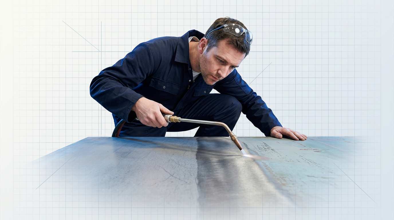
With the cleaning pass complete, the surface needs to be read carefully — not glanced at.
Use good lighting: natural daylight or a directed artificial source works well.
Examine the cleaned area at multiple angles rather than looking straight down at it.
The most useful technique is raking light: hold a torch or work light at a low angle so the beam skims across the surface.
Raking light reveals surface texture changes and residual coating that a flat-on inspection will miss entirely.
Check for these signs that coating remains on the surface:
- Visible residue or streaks: Patches or lines of coating still present on the surface, often showing the original paint colour.
- Colour variation across the area: A patchy appearance where some zones are fully clean and others retain coating — inconsistent tone is a reliable indicator.
- Tacky or rough feel: Run a gloved finger across the surface. Areas where coating is still partially present will feel different from fully cleaned bare metal.
Then check the substrate itself for signs it has been affected beyond what correct parameters should produce:
- Discolouration or heat tinting: Colour changes in the metal itself — blues, yellows, or browns on steel — indicate the substrate absorbed more heat than it should have.
- Micro-melting: A glossy or re-solidified appearance on the metal surface, distinct from the normal matte or satin look of a correctly cleaned substrate.
- Surface texture change: Roughness or pitting that was not present before treatment and cannot be attributed to the original coating condition.
- Warping: On thin-section components, excessive energy input can cause distortion. Check flat sections against a straight edge if warping is a concern.
If coating remains in isolated spots rather than across the whole surface, run additional passes at the parameters already validated in Step 4.
The initial pass may have lifted but not fully ablated the coating in those areas — targeted additional passes usually resolve this without any need to increase power.
Only consider raising power if multiple additional passes at your validated settings produce no improvement in those localised areas.
If insufficient removal is widespread across the surface, the issue is not technique — it is parameters. Return to Step 2 and reassess.
The most likely explanations are that the coating is thicker than your Step 1 assessment indicated, or that the coating type differs from what was assumed — for example, an inorganic or ceramic coating with a much higher ablation threshold than a standard organic paint.
If you are working to a formal surface preparation grade for a downstream process — re-coating, pre-weld preparation, or NDT inspection — ISO 8501-1 provides the established visual reference scale for cleanliness on steel substrates and is the recognised tool for confirming you have met the required grade.
Once both criteria are confirmed — no residual coating, substrate intact — you are clear to proceed to Step 7.
If either criterion is not met, do not move to cleanup. Address the finding first, using the decision logic above to determine whether you return to Step 2 or run additional passes.
Step 7
Clean Up and Document the Job
Key Insights
Wipe residue; no solvents unless required.
No bare hands — skin oils kill adhesion.
Paint loads filters faster — check after jobs.
Check MSDS before disposing of filters.
Inspect lens window; replace if contaminated.
Document settings, pass count, result.
With your inspection confirmed in Step 6, the job is done — but the procedure isn't closed until you've handled what the cleaning pass left behind.
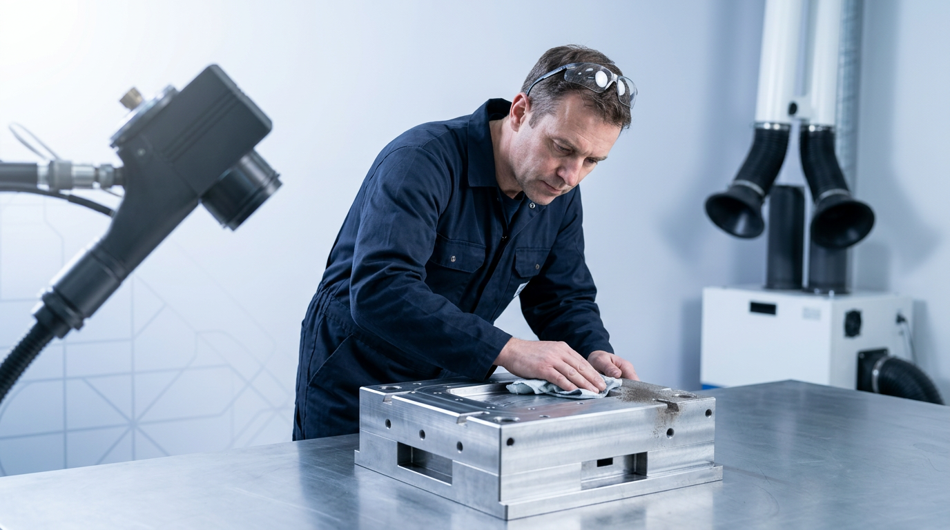
Start with the surface itself. Fine particulate from the ablated coating often settles on or near the cleaned area during the pass.
- Remove loose residue: Use a clean, dry, lint-free cloth or a low-pressure air blow-off to clear ablation particulate from the cleaned surface before any downstream process — re-coating, welding, bonding, or inspection.
- Avoid solvents: Do not use solvents to wipe the surface unless your specific downstream process requires them. Solvents can recontaminate a freshly cleaned metal surface and undo the work you've just completed.
Once the surface is clear, keep it that way: do not touch the cleaned substrate with bare hands before the downstream process begins.
Skin oils deposited on a freshly cleaned metal surface can compromise adhesion for re-coating or bonding just as effectively as residual paint. Handle the workpiece with gloves from this point forward.
Next, turn your attention to the fume extraction unit. Paint removal places a heavier load on filters than lighter oxide or rust cleaning — the volume and composition of ablated particulate is significantly greater, and filters saturate faster as a result.
Check the extraction unit's filter condition following the manufacturer's saturation indicators and recommended replacement intervals. A multi-stage system typically runs a pre-filter, a HEPA stage, and an activated carbon stage — inspect each according to the manufacturer's guidance, not just the outermost layer.
Saturated filters from paint removal work require careful disposal. Depending on the coating you removed, the captured particulate may contain lead compounds, chromate-based primers, VOCs, or other regulated substances.
Consult the Material Safety Data Sheet (MSDS) for the coating you removed to understand what the filter has captured, then dispose of saturated filters in accordance with your local waste regulations. This is a standard occupational health step — treat it as one.
Finally, inspect the cleaning head's protective lens window. Ablation smoke deposits on the lens during operation and, if left unchecked, degrades beam quality on subsequent jobs.
Lens protection windows are a standard replaceable consumable on professional laser cleaning systems. If the window shows contamination, replace it following the machine manufacturer's guidance before the next job.
Close the job by documenting the validated parameters you used: substrate type, coating type, power settings, scan width, pass count, and the result achieved.
The parameters validated in your test pass and confirmed across the full cleaning run are now a proven reference. Record them — experienced operators build a library of validated parameter sets over time, and each completed job is how that library grows.
Ready to Put the Process Into Practice?
You've worked through the full workflow. If you want to talk through your specific application with an expert, a 30-minute call is the fastest way to get answers.
Conclusion
A Clean Substrate, Ready for What Comes Next
The surface is clean to the substrate, free of residue, and undamaged — ready for primer, welding, bonding, or NDT inspection.
Every decision here was grounded in the one before it: assessment drove parameters, parameters were validated, and the result was confirmed before the job closed.
The parameter record you documented is your starting point the next time you work the same substrate and coating combination.
When volume grows, AutoLASE takes it further — load the part, machine vision builds a 3D map, and the clean runs automatically, no programming required.
Laser Paint Removal: Frequently Asked Questions
Practical answers to the questions that come up most often — from open-workshop operation and selective layer removal to troubleshooting persistent residue and understanding what substrates laser cleaning works on.
With a conventional Class IV laser cleaning system, no — the area around the work must be controlled and bystanders protected before the laser fires. In practice, that means restricting access, posting warning signs, and often clearing the surrounding area entirely. For shared or mixed-use workshops, that overhead is a significant operational constraint. The ELASER-RHZ from Woodrow Scientific changes this. Using WSL's patented, world-first reduced hazard zone technology, the laser hazard is confined to a small area immediately around the work itself. That makes continuous operation possible in open-plan manufacturing facilities, mixed-use workshops, and even publicly accessible spaces — without full area evacuation or shutdown between jobs. This is a genuinely unique capability: WSL is the only manufacturer to have achieved this, and it is protected by patent. For operators who need to laser remove paint in environments where clearing the area is impractical, the ELASER-RHZ is the only system that removes that barrier. WSL provides full operator training as standard, so the expanded range of environments this unlocks is available from day one.
Yes. By controlling the number of passes and the fluence (energy density delivered per unit area), a laser can remove a topcoat while leaving the primer intact — or strip selectively to any defined layer in the coating system. Each pass removes a defined depth of coating. Stopping after the topcoat is lifted and before the primer is reached is achievable with conservative settings and a measured, pass-by-pass approach, with inspection between each pass. This selective capability is one of the practical advantages laser cleaning holds over abrasive or chemical methods, which tend to remove all layers indiscriminately. Abrasives cut through everything in their path; chemicals attack the full coating stack. A laser, correctly set, can be precise about where it stops.
The clearest signs are visual: discolouration or heat tinting of the metal surface beyond the cleaned zone; visible changes in surface texture or roughness; a glossy or re-solidified appearance on metal (indicating micro-melting); or warping on thin-section material. Any of these indicates that fluence has exceeded the substrate's damage threshold. The corrective action is straightforward: reduce power, increase scan speed, or widen scan width — then re-test on a scrap piece before continuing on the production surface. These signs are most likely to appear on aluminium alloys and thin-section components, which have a narrower safe operating window than steel. If you are working on either, start conservatively and step up gradually rather than beginning at the settings that worked on a thicker steel part.
If additional passes at your current settings produce no improvement, increase power incrementally and re-test on a scrap piece before continuing on the production surface. Persistent residue after multiple passes is almost always a coating identification problem, not a machine problem. Some industrial coatings — inorganic zinc primers, ceramic thermal spray coatings, and certain epoxy formulations — require significantly higher fluence than standard organic paints. If the coating behaves differently from what you expected, go back to the surface assessment from Step 1 and verify what you are actually dealing with. On very thick coatings, more passes than initially estimated may simply be required. Multiple moderate-power passes are safer and produce better edge quality than a single aggressive high-power pass — resist the temptation to jump straight to maximum power.
The meaningful metric is area rate — how much surface area the system can process per hour — not a simple time figure. That rate depends on machine power, coating thickness, and the number of passes required, so there is no single universal answer. Higher power enables faster travel speed or fewer passes for the same coating, increasing throughput. Thicker or harder coatings require slower speeds or more passes, which reduces it. For handheld operation, operator travel speed consistency is also a variable. Experienced operators maintain steadier speed and achieve more predictable throughput than novices — which is one reason the test pass discipline covered earlier in this guide pays off over time. Because strip rate varies so much by coating type, thickness, and substrate, any specific figure quoted without those context details should be treated with caution.
Yes. Laser cleaning effectively removes paint and other coatings from metal, stone, and masonry surfaces by ablating the coating — converting it to vapour and fine particulate — without damaging the underlying substrate, provided the laser parameters are correctly set for the specific coating and surface combination. The process works by delivering focused laser energy at a fluence above the coating's ablation threshold but below the substrate's damage threshold. When parameters are correctly set, the beam stops at the base material. It handles a wide range of coating types: thin decorative paint, thick industrial epoxy, powder coatings, lacquers, primers, and more. That breadth makes it a versatile surface preparation tool across industries from automotive and aerospace to heritage restoration.
The primary substrate categories are metals — including carbon steel, stainless steel, galvanised steel, aluminium alloys, copper, brass, bronze, titanium, and cast iron — and non-metals such as stone, concrete, brick, and masonry. Substrate material matters because it determines the safe operating window for fluence. Steel has a wide window and tolerates a broad range of settings. Aluminium alloys have a narrower window and require more conservative parameters — as covered in the substrate assessment step. Stone and masonry are handled at lower fluence to preserve surface detail and avoid micro-fracturing. The list above covers the common scenarios; the process is not limited to these materials, but as substrates become more unusual, parameter guidance becomes more application-specific. If you are working on a substrate not listed here, testing on scrap material before committing to the production surface is especially important.