

Introduction
If you work with laser marking — as an engineer, production manager, or technical buyer — you have probably encountered a part that is not flat and wondered why the results were so hard to get right.
Curved surfaces expose a fundamental limitation of conventional flat-field systems: marks that look acceptable at the centre degrade toward the edges, and machine-readable codes that pass on flat stock fail to scan reliably on a cylinder.
This guide works through the full picture — from why flat-field systems struggle, through the principles that make 3D marking possible, to software integration, real-world applications, and what adoption looks like in practice.
It goes into genuine depth, written to be followed by anyone with a working knowledge of laser marking — no photonics background required.
TL;DR
3D laser marking is not a refinement of conventional flat-field marking — it is a fundamentally different approach. The gap in quality, reliability, and production efficiency between the two is large enough that for anyone regularly marking curved or complex-geometry parts, the case for understanding the technology is straightforward.
This article covers:

Why flat-field laser marking fails on curved surfaces
Optical and mechanical principles of 3D marking
Legacy workarounds and their limitations
Software, CAD integration, and machine vision
Industry applications and real geometric problems solved
Production efficiency and adoption considerations
What is 3D marking?
Marking a curved surface with a laser sounds straightforward — until you consider that a conventional laser marking system has no mechanism to follow that curve. The beam fires into a fixed focal plane, and anything that deviates from that plane falls outside the system's operating envelope. 3D laser marking exists precisely to close that gap.
In a 3D marking system, the laser's focal point shifts dynamically along the Z axis as the beam traverses the part — without any physical movement of the scan head or the workpiece. The system reads the surface geometry and adjusts focus in real time, keeping the beam sharp and consistent across contours, curves, and height changes that would defeat a conventional setup.
In a conventional 2D flat-field laser marking system, the focal plane is fixed at a single working distance from the scan head. Every point on the surface being marked must sit at exactly that distance; even a deviation of a few millimetres is enough to push the beam out of focus.
A conventional 2D system marks within a flat plane. A 3D marking system marks within a bounded three-dimensional volume — a defined XYZ space in which the focal point is maintained dynamically as the beam moves. This shift from field to volume is the defining conceptual difference between the two technologies.
Three core components make this marking volume possible. Galvanometer mirrors handle XY beam steering, as they do in any galvo-based marking system. A dynamic focusing element — typically a sliding expander lens or a third galvo axis (sometimes called a Z-galvanometer) — provides independent Z-axis focal control. Coordinating all three axes simultaneously is the job of geometry-aware control software, which processes surface data and drives the optics in concert so that focus, position, and marking speed remain consistent throughout the scan.
Together, these components allow a 3D marking system to address surface geometries that are simply incompatible with flat-field operation.
- Cylindrical surfaces: Round or tubular parts where the surface curves continuously around a central axis, such as pipes, shafts, or bottles.
- Conical surfaces: Tapered forms where the surface angle changes along the part's length, common in nozzles, fittings, and tool shanks.
- Spherical surfaces: Curved surfaces that change in two directions simultaneously, such as ball joints, domes, or rounded medical implants.
- Stepped (multi-level) surfaces: Parts with distinct height changes between flat regions, where a single focal plane cannot cover all levels at once.
- Inclined (tilted) surfaces: Flat surfaces presented at an angle to the scan head, requiring progressive Z compensation across the marking field.
- Freeform surfaces: Complex, non-geometric contours with continuously varying curvature in multiple axes, typical of consumer product housings and aerospace components.
It is worth distinguishing 3D marking from the mechanical workarounds engineers have historically used on curved parts — rotating the workpiece with a rotary fixture, stepping the scan head to different Z positions between passes, or deploying multi-axis robotics to reposition the optics. Those approaches solve the curved-surface problem by moving something physical; 3D marking solves it optically and electronically, within a single, stationary scan head.
With that definition in place, it becomes easier to appreciate what is actually at stake when a conventional flat-field system is asked to mark a curved part — which is exactly what the next section examines.
Why Flat-Field Laser Marking Fails on Curved Surfaces
If you have ever marked a cylindrical part and noticed the centre looks sharp while the edges fade, blur, or distort, you have already seen the physics at work — you just may not have had a name for it.
Every flat-field laser marking system operates within a depth of focus: a narrow axial window along the Z axis within which the beam maintains its minimum spot size and maximum energy density.
Inside that window, the beam is concentrated and consistent. Outside it, the focused spot grows, energy spreads over a larger area, and the power density at the surface drops — sometimes sharply.
On a flat surface held perpendicular to the beam, the entire marking area sits within that window and results are predictable. The moment the surface curves, different points on that surface sit at different distances from the lens, and the depth-of-focus constraint becomes a direct source of marking failure.
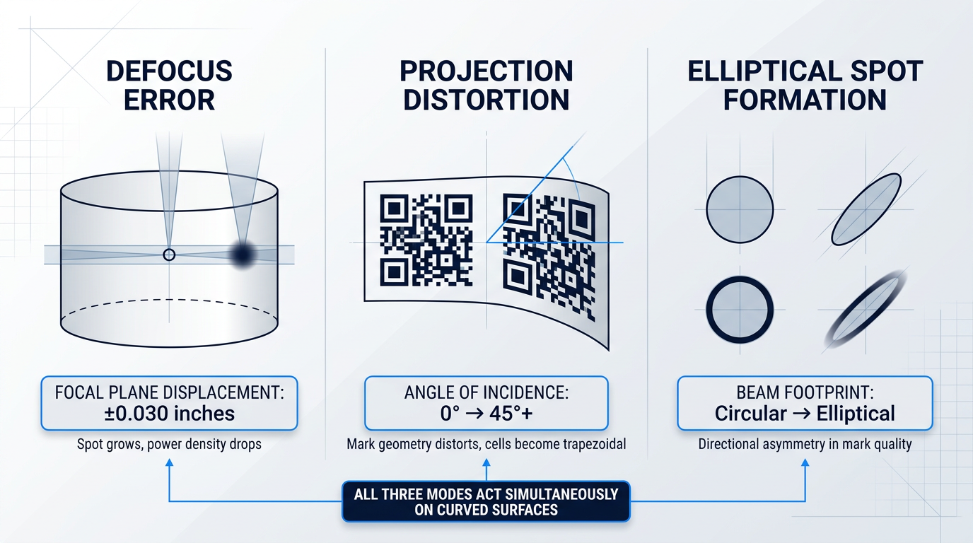
The consequence is a defocus error: as the beam scans toward the rising or falling edges of a curved surface, it arrives before or after reaching its minimum spot size, producing wider lines, reduced contrast, and degraded edge definition.
This degradation is not gradual and forgiving. According to Jimani's laser marking engineers, a surface displaced by as little as .030 inches from the focal plane on a narrow lens will produce a noticeably softer result — and the impact compounds with distance.
Defocus is the primary failure mode, but it is not the only one. A second, mechanically distinct problem arises from projection distortion: as the beam scans away from the optical axis and strikes a curved surface at an increasing angle of incidence, the geometry of the mark itself distorts.
On a flat surface, the optics correct for the beam's angular sweep so that marks render with accurate geometry. On a curved surface, that correction no longer applies uniformly — the beam footprint stretches along the surface, and what should be a straight line becomes bowed, or a square Data Matrix cell becomes trapezoidal.
This is a geometric problem, entirely separate from the energy-density problem of defocus. A material that tolerates modest defocus may still produce a geometrically distorted mark simply because the beam is striking the surface at the wrong angle.
A third failure mode compounds both of the above on strongly curved surfaces: the non-normal angle of incidence causes the beam's cross-section at the surface to become elliptical rather than circular.
A circular beam arriving at an oblique angle casts an elliptical spot on the surface — the same total energy is now spread over a larger, asymmetric footprint, reducing effective energy density further and introducing directional asymmetry into the mark.
The mark quality differs along the two axes of the ellipse: lines running parallel to the long axis of the spot appear wider and softer than those running perpendicular to it. This effect is most pronounced on small-diameter cylindrical parts and spherical surfaces, where the beam angle changes rapidly across a short arc.
On a 1-inch diameter cylindrical part, a flat-field laser can mark roughly 60° around the circumference before defocus visibly degrades mark quality. Beyond that arc, the surface deviation from the focal plane is large enough to produce inconsistent results — and distortion compounds the problem further.
What makes curved-surface marking particularly difficult is that all three failure modes act simultaneously on the same surface.
A cylinder presents defocus errors as the beam moves off-axis, projection distortion as the beam footprint stretches across the curved profile, and elliptical spot formation as the angle of incidence steepens — each mechanism reinforcing the others, which is why the overall degradation is often sharper than any single effect would predict in isolation.
Why This Matters Beyond Mark Appearance
It is tempting to frame these failure modes as cosmetic — a mark that looks a little soft at the edges. In practice, the consequences are functional and, in regulated industries, regulatory.
A Data Matrix code applied across a curved surface may scan correctly at the centre, where focus is maintained, and fail entirely at the edges, where defocus and projection distortion compound. The code grades as unreadable not because it is worn or damaged, but because its cells are geometrically distorted and contrast-degraded from the moment it was marked.
In medical device manufacturing and automotive traceability, a partially readable or geometrically distorted code means a non-compliant part — triggering a failed inspection, a rejected assembly, or a costly rework cycle.
The problem is compounded by where traceability codes are often required to go: directly onto the part geometry, not onto a flat label or a machined pad. Curved housings, implant bodies, and shaft surfaces are frequently the only available marking real estate.
The surface geometries that trigger these failure modes most consistently are not exotic edge cases — they are common engineering forms found across industries.
- Small-diameter cylindrical shafts: Tight radius means the beam angle and focal distance change rapidly across even a narrow arc, compressing the usable marking window severely.
- Spherical surfaces: Curvature in two directions simultaneously causes focal distance and angle of incidence to shift continuously, making uniform marking across the surface practically impossible without compensation.
- Conical housings: The taper continuously changes the beam-to-surface distance along the Z axis, producing a gradient of defocus and distortion across any mark that spans the cone.
- Stepped multi-level components: Height differences between adjacent surfaces exceed the depth of focus, causing abrupt mark quality changes at each step transition — particularly problematic for codes that span both levels.
Each of these geometries violates the flat-field system's core assumption — that the surface being marked is a flat plane held perpendicular to the beam — in a different way, which is why no single workaround within the flat-field paradigm resolves all of them.
Understanding these failure modes precisely is what makes the engineering of 3D marking systems legible — the next section explains how the technology is designed to resolve each of them.
Optical and Mechanical Principles of 3D Marking Systems
Every failure mode that conventional laser marking produces on curved surfaces traces back to a single architectural constraint: the focal point is fixed. Understanding how 3D marking systems solve that problem requires looking at what the standard architecture actually is, and precisely what it lacks.
The 2-axis baseline: galvo mirrors and the f-theta lens
A standard flat-field laser marking head is built around two galvanometer mirrors — one steering the beam along the X axis, one along the Y — both positioned before the focusing lens in what is called pre-objective scanning: the mirrors handle beam steering, and the lens handles focusing.
The focusing lens in these systems is an f-theta lens, a specially designed optical element whose name describes its core property: spot displacement on the focal plane is linearly proportional to the scan angle, expressed as displacement = f × θ, where f is the focal length and θ is the scan angle.
The f-theta lens also corrects field curvature — without it, the focal surface would be a sphere centred on the scan pivot, not a flat plane, meaning marks near the field edges would defocus even on a flat part.
This architecture is optimised for flat surfaces, and on flat surfaces it performs excellently. The limitation is equally precise: the f-theta lens corrects field curvature across a single flat plane at a fixed working distance, and it has no mechanism to respond to Z-axis variation in the part surface.
Upgrading to a higher-quality f-theta lens does not change this. The f-theta lens is a passive, fixed optical element — no moving parts, no dynamic response, optimised for one working distance. Z-axis surface variation demands a dynamic response that a passive lens is constitutionally unable to provide.
Adding the third axis: dynamic focusing
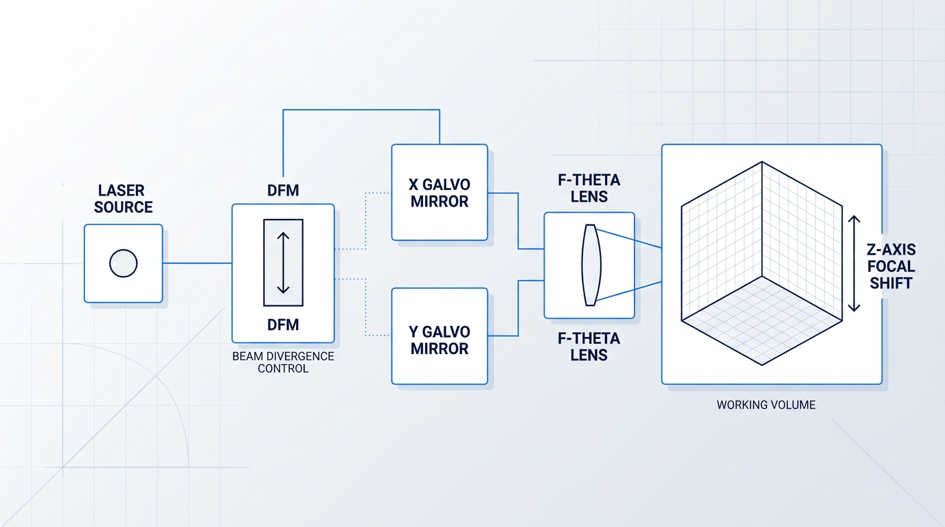
The architectural solution is a third axis of control: a dynamic focusing element inserted into the beam path upstream of the XY galvo mirrors, capable of shifting the focal point along the Z axis in real time and independently of the X and Y scan axes.
The dominant implementation in production marking systems is the dynamic focusing module (DFM), also called a sliding expander lens: a beam-expanding lens element that moves axially along the beam path under motorised control.
The mechanism works through beam divergence: moving the expander lens closer to the laser output increases beam divergence entering the focusing optics, which shifts the focal point closer to the lens; moving it further reduces divergence and shifts the focal point away.
An alternative implementation is the Z-galvanometer (or focus galvo), a third galvanometer-driven element that adjusts the beam's wavefront curvature to shift focus without mechanical translation of a lens element — used in some high-speed systems, though less common than the DFM in production marking.
The distinction between pre-objective scanning and post-objective scanning matters here because not all 3D systems are configured the same way.
In pre-objective scanning — the standard 2-axis architecture — the galvo mirrors steer the beam before it reaches the focusing lens, which constrains the system to a single focal plane even when a DFM shifts the Z position of that plane.
In post-objective scanning, the galvo mirrors are placed after the focusing lens, which allows them to address a true 3D volume rather than simply a shifted flat plane — enabling larger field coverage and the ability to follow complex surface topographies across all three axes simultaneously.
The trade-off is optical complexity: post-objective scanning typically produces a larger spot size at field edges and requires more sophisticated optical design. Different 3D marking systems make different choices on this axis depending on the application's field size, resolution, and throughput requirements.
XYZ simultaneous control and the working volume
The architectural additions only deliver their benefit when the scan controller coordinates all three axes in real time — and the operative word is simultaneous.
A true XYZ simultaneous control system computes the correct focal position for every point in the scan pattern and commands the DFM, the X galvo, and the Y galvo together, so the beam arrives at each surface point with the focal length already correctly set — no sequential adjustment, no visible seams or focus transitions between positions.
This is the defining characteristic that separates a genuine 3D marking system from a 2D system fitted with a manual Z-axis stage: the latter repositions focus between jobs, while the former adjusts focus continuously within a single marking pass.
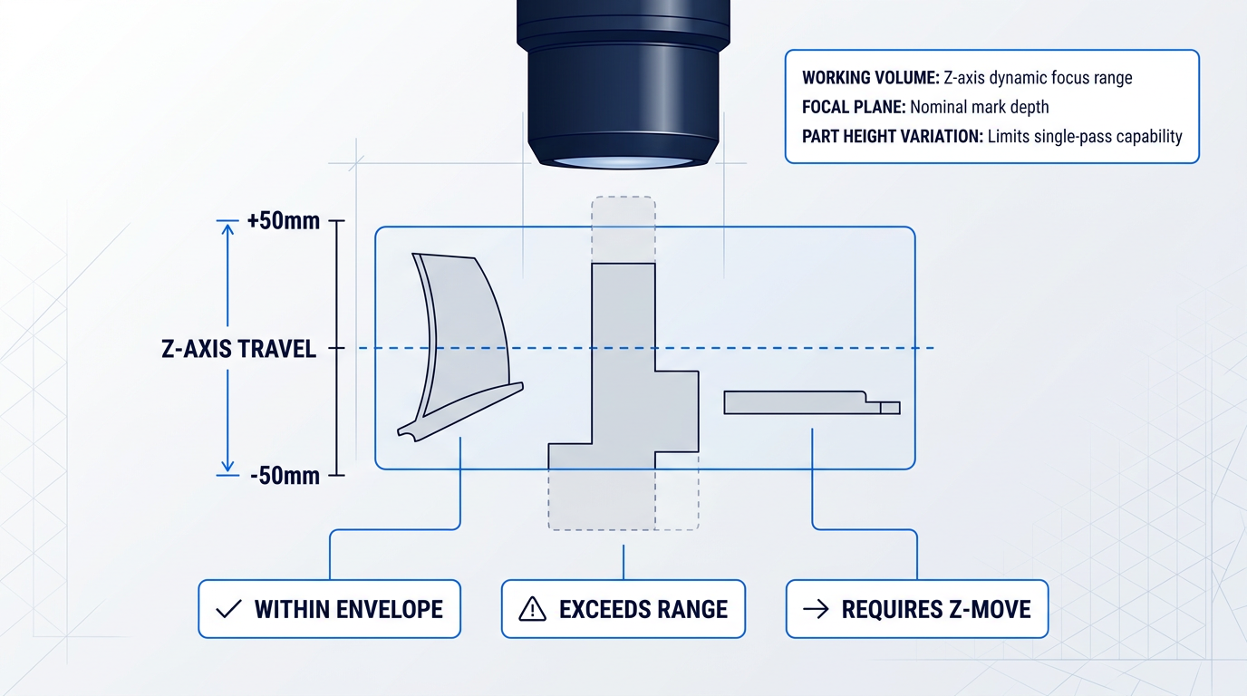
The DFM's finite physical travel range creates a practical boundary called the working volume: the bounded 3D space within which the system can maintain correct focus without any mechanical repositioning of the head or workpiece.
Parts whose surface height variation falls within this range can be marked in a single setup; parts with greater Z variation require mechanical repositioning to bring successive regions within the working volume.
The Z-axis travel of the dynamic focusing module defines the working volume: the bounded 3D space within which focus is maintained without mechanical repositioning. Specifying a system starts with confirming that the working volume encompasses the full surface height variation of the parts to be marked.
One further engineering consideration applies at the extremes of Z travel: as the focal point moves toward the limits of the DFM's range, the beam's angle of incidence on the surface increases, and the spot can become slightly elliptical rather than perfectly circular, reducing energy density marginally and introducing minor geometric distortion.
This is not a fundamental limitation of the architecture but a practical parameter to account for when specifying a system for high-precision marking — keeping the working region of the surface toward the centre of the Z travel range mitigates the effect.
The hardware architecture described here establishes what a 3D marking system is physically capable of. Realising that capability on a real part requires a software layer that translates surface geometry into per-point focal positions and corrects for the geometric distortions that curved surfaces introduce into the scan pattern — which is the subject of the next section.
Mechanical Workarounds for Curved Surface Marking
Most engineers working with cylindrical or complex-geometry parts have built production lines around at least one of these approaches — and for good reason. Before 3D dynamic focus systems became accessible, rotary attachments, Z-axis repositioning, multi-axis robotics, and precision fixturing were the only available tools for maintaining marking quality on non-planar surfaces. They work. But each carries a structural overhead in cycle time, tooling investment, or operational flexibility that is worth understanding clearly before choosing between the old paradigm and the new.
The Four Established Workaround Approaches
Each method solves the core problem — keeping the laser beam in focus on a curved surface — through a different mechanical strategy, and each brings its own cost profile.
- Rotary attachments: The part rotates while the laser head stays stationary, maintaining constant focal distance on cylindrical surfaces. Enables full 360° circumferential marking in segmented passes.
- Mechanical Z-axis repositioning: The laser head or workpiece is raised or lowered between passes to bring each height zone into the focal plane. Sequential and often operator-dependent.
- Multi-axis robotics: Laser delivery optics are mounted on a robot arm that follows complex 3D surface contours. Capable but expensive, requiring skilled path programming per geometry.
- Precision fixturing: Part-specific jigs hold components in exact position so the marking area sits within a standard 2D system's focal plane. Tooling cost and lead time scale with part variety.
Rotary attachments remain among the most widely deployed solutions for cylindrical components. The operating principle is straightforward: a motorised chuck or spindle rotates the part at a speed synchronised to the laser scanner, so the beam always strikes the surface at a consistent focal distance.
The limitation is not capability but overhead: the setup requires a part-specific chuck or fixture, the rotary axis must be mechanically aligned to the galvo scanner, and segmented marking introduces brief indexing pauses between passes as the part advances to the next angular position.
Mechanical Z-axis repositioning addresses multi-level parts by physically moving the laser head or workpiece between marking passes — each height zone is brought sequentially into the focal plane and marked before the system moves to the next level.
This approach is particularly error-prone on parts with irregular or compound height profiles: the correct focal offset for each zone must be measured or programmed individually, and any miscalculation produces defocused marks on that level. FOBA's documentation on multi-level surface marking characterises these mechanical adjustments as time-consuming and prone to error, especially on complex geometries.
Multi-axis robotic cells represent the most capable mechanical workaround — by mounting the laser delivery optics on a 6-axis robot arm, the system can follow genuinely complex 3D surface contours that neither rotary nor Z-axis repositioning can address.
The trade-off is substantial: robot cells require significant capital investment, and programming a new part geometry is a meaningful engineering task that demands skilled integrators. Each new part profile requires its own verified path programme before production can begin.
Precision fixturing takes the opposite approach — rather than moving the laser to follow the part, it constrains the part so that the marking area always sits within the focal plane of a standard 2D system. For aerospace applications, Lasit Laser's documentation notes that dedicated fixture design and fabrication typically requires 2 to 6 weeks of development time, with tooling costs reaching 5,000–15,000 euros for articulated geometries.
Setup changeover between part types adds a further 15–30 minutes of downtime per batch, and any change to part geometry — even a minor dimensional revision — renders the existing fixture obsolete and restarts the tooling cycle.
The Structural Penalties All Workarounds Share
Whatever the specific mechanism, every mechanical workaround imposes a throughput penalty that is structural rather than incidental: the laser is idle while the mechanics move.
Rotary indexing pauses between segments, Z-axis repositioning between height levels, robot arm traversal between surface zones — in each case, the marking source sits idle waiting for a mechanical system to complete its motion before the next pass can begin. At high production volumes, this directly constrains cycle time and line scalability.
The second shared penalty is inflexibility to geometry change. Fixtures are designed around a specific part form; rotary setups are configured for a specific diameter and chuck geometry. When a part design changes — even slightly — the tooling must be redesigned, manufactured, and validated before production resumes.
For product lines with frequent geometry variation or high part-type diversity, this creates a compounding lead-time burden: each new variant requires its own tooling cycle, and the cumulative cost across a product family can be considerable.
It is also worth being direct about where mechanical rotation remains the correct engineering choice. Keyence's guidance on 3-axis laser marking systems states that a rotary attachment is still necessary when marks exceed the laser's reach around a curved surface — typically around 120–160 degrees depending on the material. For applications requiring a complete circumferential band or full-wrap text around a cylinder, mechanical rotation is the appropriate solution; a 3D dynamic focus system is not designed to replace it.
Keyence documents that 3-axis laser systems still require a rotary attachment when marks exceed approximately 120–160 degrees of arc around a curved surface. For partial-arc and complex-geometry marking, 3D dynamic focus eliminates mechanical overhead. For full circumference marking, rotary remains the correct tool. Specifying the right method depends on arc coverage, not on which technology is newer.
The practical question for any production engineer is therefore not whether mechanical workarounds can do the job, but whether the overhead they carry — in tooling investment, setup time, indexing dwell, and geometry-change lead time — is justified by the application's actual requirements.
What 3D dynamic focus systems eliminate is the mechanical layer of that overhead. But as the next section covers, the advantage is not purely optical: the software layer that drives geometry-aware path generation and vision-based part alignment is equally important — and it is that software capability that makes precision fixturing largely unnecessary for a wide class of curved-surface marking applications.
Software, CAD Integration, and Surface Geometry Translation
The hardware described in the previous sections solves one half of the 3D marking problem: keeping the beam focused as it traverses a curved surface. But hardware alone cannot know the shape of the part sitting on the work table. That knowledge comes from the software layer — and how a system acquires, represents, and acts on surface geometry is what separates a production-ready 3D marking system from one that demands constant manual intervention.
How the System Acquires Surface Geometry
There are three distinct methods by which 3D marking software can obtain a mathematical description of the surface it is about to mark — each suited to a different class of part and production context.
- CAD model import: The software ingests a 3D model file (STEP, AutoCAD, SolidWorks formats are supported) and uses the surface geometry to pre-calculate the correct focal position and scan path for every point on the marking area.
- Geometric primitives: For standard shapes — cylinders, cones, spheres, inclined planes — the operator enters defining parameters such as diameter, radius, or angle. No CAD file is needed; the software constructs the surface description from those values.
- Active surface profiling: On advanced systems, a pre-mark scan acquires a 3D point cloud of the actual part surface, building a topographic map of the real geometry rather than relying on a nominal model.
The practical workflow choice is straightforward: CAD model integration is the right approach for complex freeform surfaces where a complete geometric description already exists as part of the design process; geometric primitives offer a faster setup path for well-defined standard shapes where entering a diameter or inclination angle is quicker than importing a file.
Whichever input method is used, the outcome is the same — the software holds a mathematical description of the surface and can compute where every scan point needs to be in XYZ space before the first pulse fires.
Projection Distortion Correction
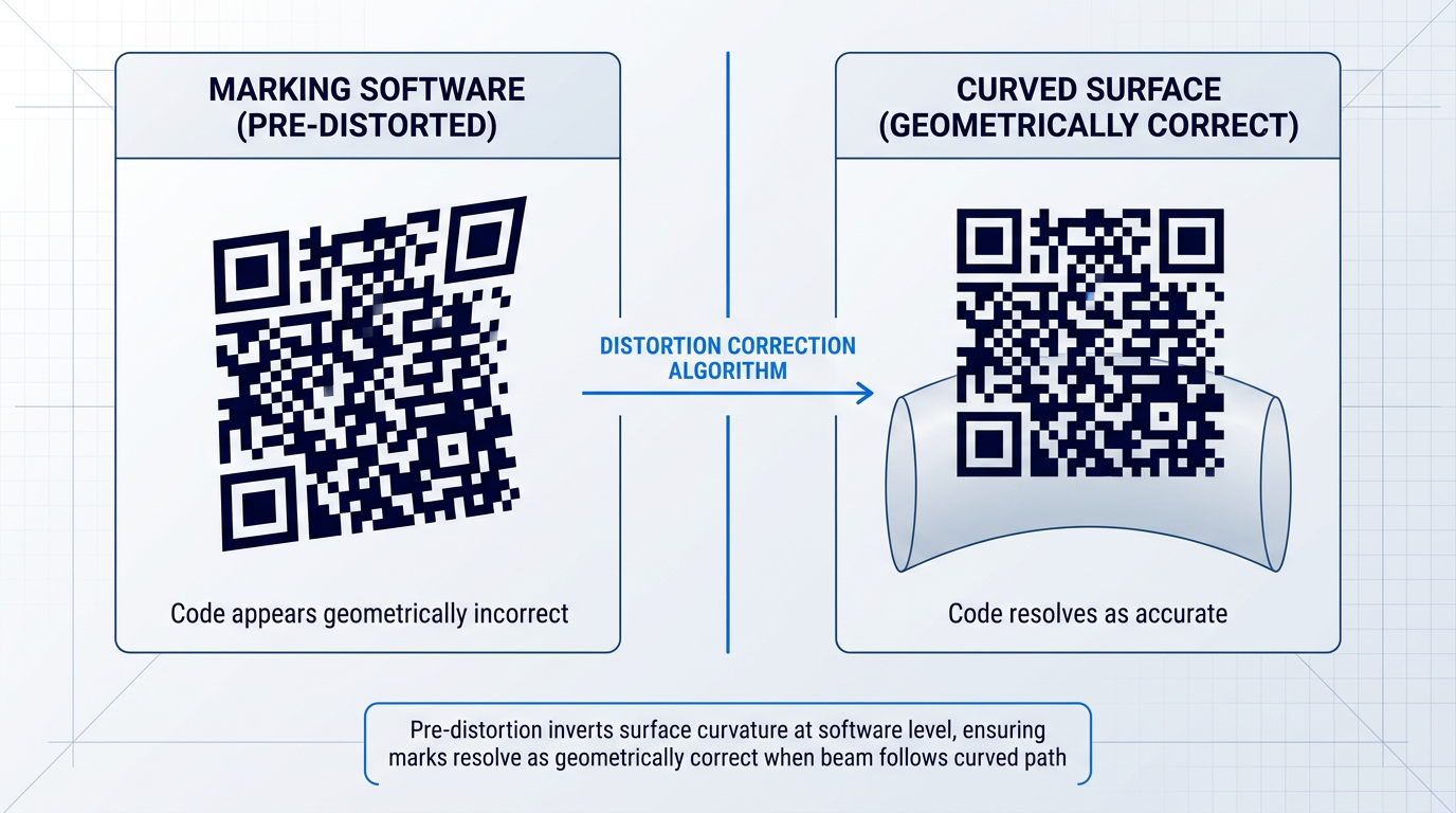
Geometry acquisition alone is not sufficient. When marking content — text, a Data Matrix code, a logo — is applied to a curved surface, a system that simply projects the mark as if the surface were flat will produce visible geometric distortion: straight lines bow, square codes stretch, and character spacing becomes uneven across the arc.
Distortion correction inverts this problem at the software level: the mark layout is pre-distorted in the opposite direction before the scan path is generated, so that when the beam follows the curved surface, the mark resolves as geometrically correct to the eye and to any downstream reader or inspection system.
This is the software counterpart to the hardware's Z-axis focal control described earlier — where the dynamic focusing element keeps the beam sharp across height variation, the wrap algorithm keeps the mark's geometry accurate across the surface's curvature. TRUMPF, for instance, describes the wrap algorithms in its TruTops Mark 3D software as guaranteeing an undistorted and aesthetically correct marking on three-dimensional surfaces including inclined planes and freeform objects.
Automatic Segmentation for Large Surfaces
When a marking area exceeds the system's working volume — or when significant height variation across the surface pushes beyond the Z-axis travel range of the dynamic focusing element — the software divides the job into sub-blocks automatically.
Each sub-block is processed at the correct focal length calculated for that portion of the surface, and the software positions segment boundaries so that individual marking objects fall completely within a single block, preventing any breaks in lines or hatched fills. The operator does not manage this division manually; smart segmentation handles the sequencing transparently.
Point Cloud Surface Profiling
CAD models describe nominal geometry — the part as designed. For components where actual geometry may deviate from nominal (castings, forgings, or parts with significant manufacturing variation), some advanced systems go further by actively measuring the part before marking.
Using methods such as structured light, laser triangulation, or integrated low-power continuous-wave laser measurement, these systems acquire a 3D point cloud of the specific part surface in front of the system — capturing real deformation, tolerance deviation, and orientation — and use that topographic map to define the processing beam's focus path.
The significance of this approach is that it requires no prior knowledge of the workpiece's exact shape or orientation: the system measures first, then marks. Research published in academic literature confirms that integrating 3D surface measurement with the marking system itself — using the same optical path for both measurement and processing — eliminates the need for precise part pre-positioning and substantially increases processing flexibility between successive marks.
Machine Vision for Part Placement Compensation
Even with perfect surface geometry knowledge, a mark will be misaligned if the part is not placed in exactly the same position and orientation each time. In practice, operator variability in part loading and tolerance stack-up between parts in a batch mean that positional variation is the norm, not the exception.
Machine vision systems address this by detecting the actual position, orientation, and height of the part before marking begins, then adjusting the marking path to match what the camera sees rather than what the fixture assumes.
Coherent's PartVision system, for example, automatically locates parts and adjusts machine operation to ensure marks are placed correctly — eliminating the need for specialised tooling and compensating for the positional variation introduced by material handling and part transport. TRUMPF's VisionLine image processing system works similarly, identifying the actual location of the part based on defined contours and automatically keeping the marking content in the correct position.
The production implication is meaningful: the system finds the part rather than requiring the part to find the system. A real-world example from Samaplast AG, a medical device manufacturer, illustrates this directly — after integrating TruTops Mark 3D with VisionLine, operators reported placing parts directly on the work table without any fixtures, with the vision system handling alignment automatically.
Through-the-Lens Vision
A particularly elegant implementation of machine vision places the camera in the same optical path as the marking beam itself — a configuration known as through-the-lens vision.
Because the camera looks through the same optics that deliver the laser, there is no parallax error or calibration offset between what the vision system sees and where the beam lands. The system identifies the part's actual location by detecting defined contours or reference features and automatically aligns the marking content to match — with no manual repositioning required.
FOBA's IMP (Intelligent Mark Positioning) system and MOSAIC feature use this coaxial camera approach to enable marking without part fixtures: a mosaic image of the marking field is created in approximately one second, the part's position and identity are confirmed, and marking content is aligned relative to the detected part location. Coherent's PartVision is similarly described as a through-the-lens system that examines and verifies the part prior to marking, then tells the scanner how to adjust for positional variation.
A 3D marking system that requires manual geometry input for each new part type, or that cannot compensate for part-to-part positional variation, is difficult to scale in production. Geometry-aware software combined with vision-based alignment is the practical baseline for reliable, high-volume 3D marking — and the most useful criterion for engineers evaluating whether a system will perform outside tightly controlled, low-volume conditions.
With both the optical architecture and the software intelligence now established, the technology's real-world traction becomes easier to understand — and the next section examines exactly that, tracing how these capabilities play out across industries where part geometry has historically made reliable laser marking difficult.
Industry Applications of 3D Marking
Every industry covered here has a geometry problem first and a marking problem second. The following applications are not a generic list of sectors that use lasers — each one is grounded in a specific surface shape that defeats conventional flat-field marking, and the reason 3D dynamic focus solves it is always the same: the beam follows the surface rather than forcing the surface to meet the beam.
Automotive: Traceability on Curved Cast Surfaces
Pistons, cylinder heads, transmission housings, and hydraulic fittings share a common geometric reality: their surfaces are curved, cast, or machined with significant height variation across the marking zone — there is rarely a flat face large enough to reliably seat a Data Matrix code within the depth of field of a conventional flat-field system.
A degraded Data Matrix on a piston crown is not a cosmetic issue — it is a traceability failure: the code cannot be scanned, the part cannot be linked to its batch record, and the supply chain loses the audit trail that quality assurance and regulatory compliance depend on. With geometry-aware 3D marking, the system compensates for surface curvature in real time, maintaining consistent energy density across the entire code so every cell resolves cleanly.
Medical Devices: Surgical Instruments
Surgical instruments present some of the most demanding marking geometries in manufacturing: curved handles, conical shafts, stepped multi-diameter bodies, and tapered tips — almost none of which offer a flat marking surface of meaningful size.
Under EU MDR 2017/745 and FDA UDI direct marking requirements (21 CFR 801.45), reusable surgical instruments must carry a permanent, machine-readable UDI directly on the device itself.
The FDA's proposed UDI rule explicitly acknowledges that exceptions to direct marking are expected due to factors including difficulty in marking certain materials and the lack of adequate surface space — conditions that curved instrument geometries can create in practice. Manufacturers should consult qualified regulatory affairs professionals regarding their specific obligations.
Medical Devices: Implants
Spherical hip ball joints, orthopaedic components, and titanium implants represent the most geometrically extreme marking challenge in regulated manufacturing: maximally curved surfaces with minimal available marking area and, in many cases, no flat face at all. One implant manufacturer found that products with round shapes could not be marked without distorting the lettering using conventional laser systems — a problem resolved when 3D marking software allowed STEP files to be loaded and the marking path projected directly onto the actual part geometry.
Implants carry an additional constraint beyond geometry: biocompatibility. The laser must modify the surface structure without ablating residue that could compromise implant safety — no foreign matter may be introduced into the material — which frames the precision requirement as a patient safety issue, not just a production quality standard.
The FDA's proposed UDI rule states that exceptions to direct marking are expected due to 'the difficulty in marking certain material, or the lack of adequate surface space.' For implants and instruments with curved or near-spherical surfaces, a capable 3D marking system addresses both conditions directly — reducing reliance on formal exceptions.
Drinkware and Consumer Goods: Cylindrical Personalisation
Tumblers, bottles, and cylindrical cups present a different kind of geometric challenge: the surface curves away from the focal plane continuously, and marking across the visible arc without mechanical rotation requires the system to compensate for the increasing defocus at either side of centre.
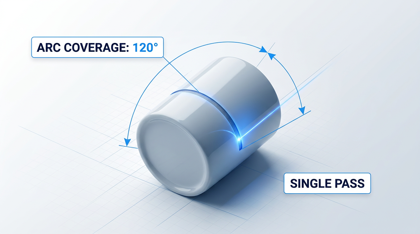
The LASIT DrinkFeeder, a dedicated drinkware marking system, supports coverage of up to 120° of arc with a 3D head in a single pass — a meaningful throughput advantage in personalisation workflows where each item carries a unique mark, since the overhead of indexing a rotary axis per item compounds at volume. Multi-cup workstation configurations allow several items to be marked in a single run.
Electronics: Miniaturised Multi-Level Components
Electronic connectors, miniaturised housings, and multi-level PCB assemblies frequently combine two compounding challenges: stepped or tapered geometries with height variation across the marking zone, and extremely small marking areas where any defocus-induced spot enlargement directly degrades code legibility.
The marking requirement — serialisation, anti-counterfeiting codes, or security features applied directly to the component — demands contactless processing with no mechanical repositioning between height levels. The smaller the component, the tighter the tolerance: a defocus error that produces only marginal quality loss on a large automotive casting can render a Data Matrix completely unreadable on a miniaturised connector housing.
Industrial Valves and Oil & Gas
Valve bodies, conical fittings, and flanges in industrial and oil & gas applications present an irregular geometry problem: surface profiles vary significantly across part types within the same product family, making custom fixturing per geometry impractical at production scale. A DN400 valve body can weigh over 200 kg, and the marking surfaces — often curved or conical — shift position depending on how the part is loaded.
The marking requirement is permanent identification for traceability and safety compliance in high-pressure, high-temperature service environments. 3D scanning with dynamic autofocus handles the geometry variation without requiring a dedicated fixture for each valve body profile — the system acquires the surface topography before marking and computes the compensated path automatically, delivering consistent Data Matrix and alphanumeric codes regardless of the part's exact loaded position.
Across all six of these industries, the pattern is consistent: the geometric challenge is specific, the marking requirement is non-negotiable, and 3D marking resolves the conflict between the two. The practical question that follows — what this means for production setup, throughput, and fixturing investment — is the subject of the next section.
Production Efficiency and Practical Considerations
Technical capability only matters if it translates to measurable outcomes on the production floor. Having covered the optics, the software, and the application landscape, the question an engineer or production manager now needs answered is a practical one: where does 3D marking pay for itself, and where does it reach its limits?
Where 3D Marking Pays for Itself in Production
Fixturing reduction is often the most immediately quantifiable gain. Vision-based alignment means parts can be placed on a work surface without precision fixtures — the system detects position and orientation automatically, eliminating the tooling cost, fabrication lead time, and changeover time that part-specific fixtures carry.
When a new part geometry enters the production schedule, a conventional system requires a new fixture to be designed, fabricated, and qualified before marking can begin. A vision-guided 3D marking system requires none of that — the geometry is handled in software, and programming a new part type reduces to defining the surface geometry and placing the artwork, not rebuilding the physical setup.
Single-setup marking of multi-level or curved surfaces eliminates the mechanical repositioning passes that add dwell time to every cycle. Where a conventional system requires the part to be moved, re-fixtured, or re-indexed between marking zones, a 3D system completes the full mark in one pass — and that cycle time reduction compounds directly across production volume.
Consistent focus maintenance across the full marking field removes the root cause of defocus-induced mark failures. In regulated industries such as medical devices and automotive, a failed traceability code does not just mean a cosmetically substandard part — it means a rejected part, with the associated inspection, rework, and compliance documentation costs attached.
- Fixturing Reduction: Vision-based alignment removes part-specific fixtures, cutting tooling cost, changeover time, and new-geometry fabrication lead time.
- Faster Part Programming: CAD-driven path generation means new part types are programmed in software — no manual focus adjustment or trial-and-error setup.
- Single-Setup Throughput: Multi-level and curved surfaces marked in one pass, eliminating repositioning cycles that add dwell time per part.
- Scrap Reduction: Consistent focus across the marking field prevents code failures that, in regulated industries, carry compliance and rework costs beyond material loss.
The same principle of machine-vision 3D scanning — scanning a part, building a 3D map, and generating a process path automatically with no manual programming — appears in adjacent laser processing domains. Woodrow Scientific's AutoLASE automated laser cleaning system applies this approach: load the part, and the system handles the geometry from there, requiring no knowledge of the part's shape or any path-setting from the operator.
Honest Constraints: Where the Technology Has Limits
The working volume of a 3D marking system is finite. The Z-axis travel of the dynamic focusing element covers a defined range above and below the nominal focal plane; components with height variation that exceeds this range require additional mechanical Z-axis movement of the head or workpiece, reintroducing some of the complexity the system is designed to reduce.
There is also a genuine trade-off between scan field size and mark resolution. Increasing the working distance expands field coverage but enlarges the spot size, reducing the resolution available for fine features. High-precision codes on small components require tighter working distances and smaller fields; large-area marking at lower resolution tolerances can use wider configurations — matching these parameters to the application is part of the system specification process.
On highly reflective materials — polished stainless steel, aluminium, and titanium are the most common examples in medical and aerospace production — varying angles of incidence across a curved surface can generate specular reflections that reduce process efficiency or produce inconsistent marks. The geometry of curved surfaces makes this more pronounced than on flat stock, and material-specific parameter selection must account for it.
3D marking systems carry a higher capital cost than standard 2D flat-field systems. The business case is strongest where the costs it displaces are already significant: high fixture tooling spend, meaningful scrap rates from defocus failures, diverse part families requiring frequent setup changes, or regulated-industry traceability requirements where a mark failure carries compliance consequences.
Before evaluating a 3D marking system on capital cost alone, quantify what the current process spends on fixture fabrication, setup changeovers, and scrapped parts from mark failures — those line items are the real comparison, and in high-mix or regulated production environments they frequently dwarf the investment difference.
With the efficiency gains and practical constraints both in view, the final step is bringing the full picture together — assessing how this technology fits a specific application, and what a realistic evaluation looks like for an operation considering the move from conventional to 3D marking.
Conclusion
Bringing it together: 3D marking in modern manufacturing
The core argument this guide has built is straightforward: curved surfaces present a geometric problem that flat-field systems cannot solve cleanly, and 3D marking is the architecturally correct response — not a workaround.
What makes it production-ready is the combination of dynamic Z-axis focus control, geometry-aware software, and machine vision: no single element is sufficient on its own.
If you are evaluating this for your own application, an honest assessment of your part geometry and marking requirements is the right starting point — followed by a conversation with a laser engineering specialist.
Frequently Asked Questions About 3D Marking
Practical answers to the capability, integration, and technology questions that arise when evaluating 3D laser marking for curved and complex-geometry parts.
No. A 3D dynamic focus system can only mark the visible face of a cylinder — typically a 60–80° arc in a single pass without any mechanical movement. The beam must maintain line-of-sight to the surface; the dynamic focusing element adjusts the focal point along the Z axis, but it cannot steer the beam around the back of the part. For full 360° circumferential marking, a rotary attachment or indexer is required to rotate the part and bring each section of the surface into the beam's working envelope. That said, many applications — a logo, part number, or traceability code on the visible face of a cylindrical component — sit comfortably within that arc. The rotary route is only necessary when the marking genuinely needs to wrap the full circumference.
Typically ±40–50 mm from the nominal focal plane, giving a total Z travel of roughly 80–100 mm — though this varies between systems and optical configurations. Beyond that range, mechanical movement of the scanning head or workpiece is required to bring the surface back within the dynamic focusing element's reach. The range is set by the physical travel of the focusing optic (a sliding expander lens or Z-galvanometer) and is tied to the focal length in use: shorter focal lengths generally offer higher energy density but a reduced Z range, while longer focal lengths extend the working envelope at the cost of spot size. Buyers should confirm the stated Z-axis range for any specific system against the actual height variation of their parts before specifying.
Not always. For common geometries — cylinders, cones, spheres, inclined planes — most 3D marking software allows the surface to be defined using geometric primitives: the operator enters the relevant parameters (diameter, angle, radius) directly, and the software calculates the correct focal path and distortion compensation without a CAD file. CAD import (typically STEP or similar formats) becomes necessary for complex freeform surfaces where the geometry cannot be adequately captured by a simple primitive. The practical implication for setup time is significant: standard cylindrical or conical parts can be programmed quickly via primitives, while freeform components — an ergonomic handle, a sculpted automotive trim piece — benefit from CAD-driven path generation to ensure accurate marking across every contour.
Vision-based alignment detects the part's actual position and orientation before marking begins, and the system compensates automatically — no precision fixturing required. A camera (either integrated through-the-lens, sharing the same optical path as the laser, or mounted externally with a wider field of view) captures the part's contours or reference features such as edges and holes. Pattern recognition algorithms calculate the offset and rotation relative to the expected position, and the marking path is adjusted accordingly before the laser fires. This approach eliminates the need for tight-tolerance fixtures and makes the system tolerant of part-to-part placement variation — particularly useful on foundry blanks, castings, or any component loaded loosely onto the work surface.
Yes, but with caveats specific to curved surfaces. Reflective metals are routinely marked with fibre lasers using appropriate parameter selection — power, pulse duration, scan speed, and frequency must be tuned to the material's absorption characteristics. On curved surfaces, the additional complication is that the angle of incidence varies across the surface: as the beam moves away from the normal, specular reflection shifts direction, reducing effective energy delivery to the surface and potentially creating inconsistent mark quality across the part. Parameter selection therefore needs to account for both the reflectivity and the geometry together. For some applications — particularly polished surfaces where reflection management is critical — surface preparation or anodising prior to marking can improve process consistency. Testing on representative real parts, rather than relying on flat-surface parameters, is the reliable way to establish a stable process recipe.
Two scenarios favour the rotary attachment. First, when full 360° circumferential marking is required — a logo or pattern that wraps continuously around a cylinder — a 3D dynamic focus system cannot achieve this in a single pass, so a rotary axis is necessary. Second, when budget constraints make adding a rotary attachment to an existing 2D flat-field system more practical than investing in a dedicated 3D marking system. For new installations where the primary requirement is full-circumference marking on predominantly cylindrical parts, a rotary-equipped 2D system can be the more cost-effective and fit-for-purpose choice. The 3D dynamic focus system earns its place when the part geometry is complex, multi-level, or freeform — stepped surfaces, sloped faces, sculpted contours — where a rotary alone cannot compensate for the geometry and maintaining focus across the full marking area requires dynamic Z-axis control.
Three laser types are most commonly paired with 3D dynamic focus scanning systems. Fibre lasers (operating around 1064 nm) are the standard choice for metals: they offer high peak power, excellent beam quality, long service life, and a cost-effective cost of ownership, making them the default for engraving, annealing, and ablation on steel, titanium, aluminium, and most other metals. UV lasers (typically 355 nm) are used for sensitive materials where the shorter wavelength enables cold marking with a minimal heat-affected zone — applications in medical devices, electronics, and fine plastics benefit from this approach. Green (frequency-doubled) lasers at 532 nm are applied to materials that absorb poorly at the infrared wavelength, including certain highly reflective metals and semiconductor materials. The 3D dynamic focusing architecture is compatible with all of these laser types — the laser source and the 3D scanning system are independent design decisions, selected to match the material and the required marking process.