

Introduction
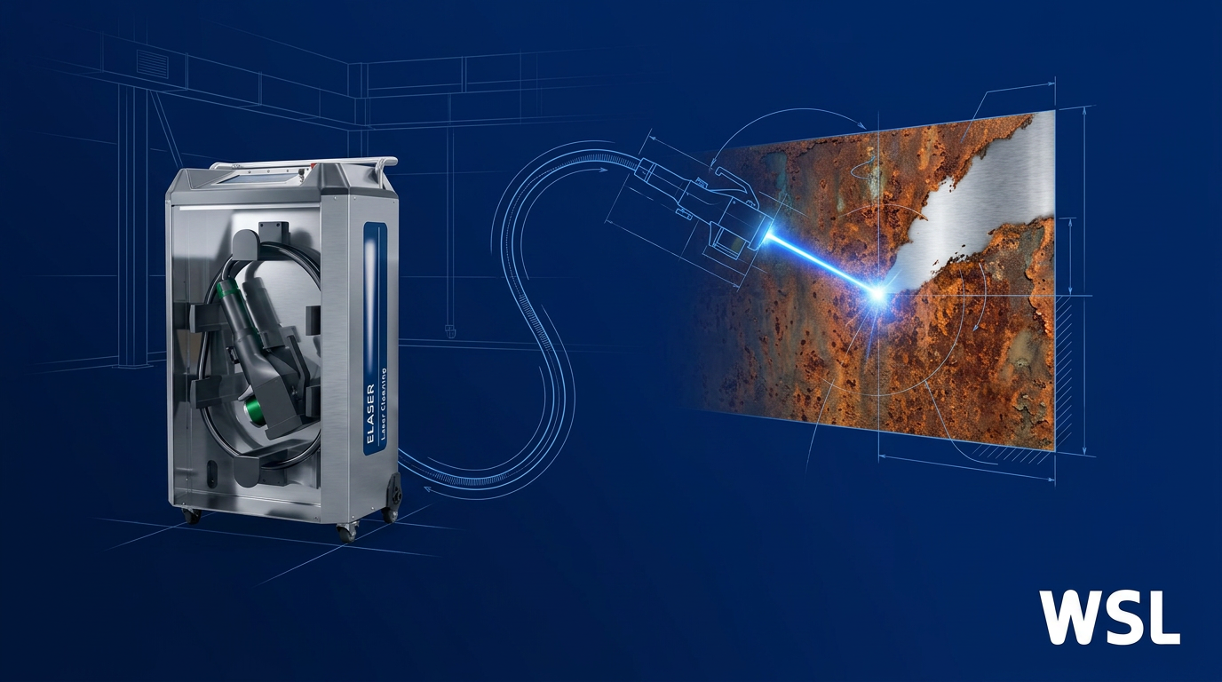
You probably already have a working sense of what laser light rust removal is — focused light energy stripping oxidation from metal surfaces without abrasives, chemicals, or contact.
What's harder to find is a clear account of how it actually works in practice: the decisions an operator makes, the variables that determine whether the result is excellent or damaging, and the full sequence from first inspection through to a verified clean surface.
That's the gap this guide fills — the operational process, step by step, with the depth that most overviews skip entirely.
TL;DR
Laser rust removal is a precise, controllable process — but the precision belongs to the operator, not the machine. The outcome depends on reading the surface correctly, setting the right parameters for that specific substrate and rust grade, and managing the process from extraction to final inspection.
Understand those variables, and the process becomes repeatable and reliable across almost any application.
This article covers:

How laser light removes rust without damaging base metal
Surface assessment and preparation before cleaning begins
Tuning laser parameters: power, frequency, scan speed
Fume and particulate extraction requirements
Post-clean inspection and verifying the result
Adapting settings for different substrates and system maintenance
What Is Laser Light Rust Removal?
Focused light stripping rust from steel without scratching, abrading, or chemically attacking the metal beneath it sounds like a contradiction — but it is exactly what happens, and the reason is grounded in straightforward physics.
The process is called laser ablation: when a focused laser beam hits a rusted surface, the energy is absorbed by the rust layer, which vaporises or is physically ejected from the surface, leaving the base metal intact underneath.
The reason the beam affects the rust but not the steel comes down to selective absorption: rust — composed primarily of iron oxides such as Fe₂O₃ and Fe₃O₄ — absorbs laser energy far more readily than clean steel does at the same wavelength.
This physical difference in optical absorption is the core mechanism behind the process's precision — minimal substrate loss is not a tuning achievement, it is the natural consequence of the material properties.
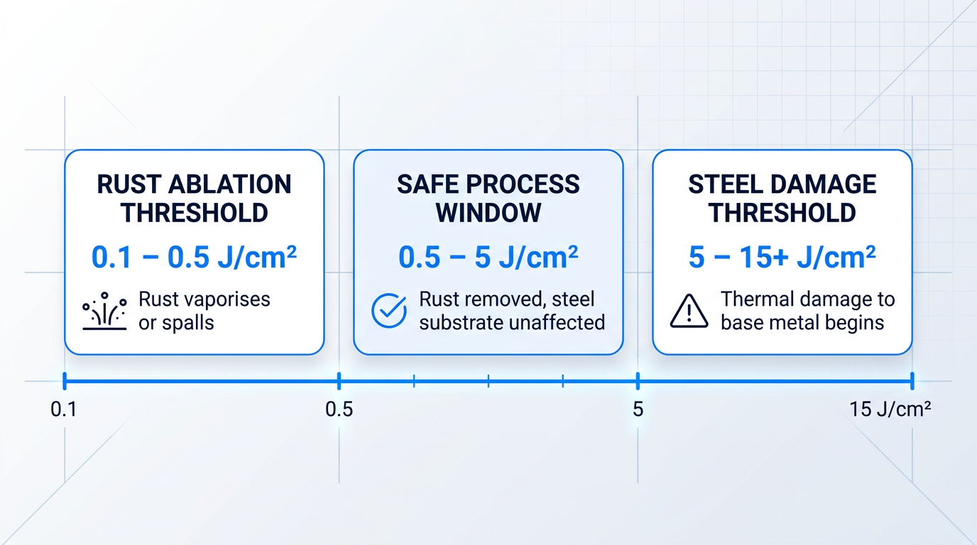
The concept becomes concrete through the ablation threshold: the minimum energy density, measured in fluence (J/cm²), required to ablate a given material. For rust and similar industrial coatings, that threshold typically falls between 0.1 and 0.5 J/cm²; for bare steel, the threshold sits far higher at roughly 5–15 J/cm².
That selectivity ratio of 10× to 150× is the operational foundation of the process — when the operator works within this window, rust is removed and the steel substrate is left thermally unaffected.
In practice, rust is removed by two related mechanisms depending on the energy level applied: at higher fluence, the rust undergoes direct vaporisation, converting to vapour; at lower fluence, rapid thermal shock causes the rust layer to fracture and be mechanically ejected in a process called spallation.
The ablation threshold for rust (0.1–0.5 J/cm²) is 10 to 150 times lower than for bare steel (5–15 J/cm²). Operating inside that window protects the substrate — the gap is a property of the materials, not a parameter the operator sets.
Both vaporisation and spallation occur in real cleaning operations — which one dominates depends on the parameters the operator sets, and the difference is visible in how the ablation plume looks and behaves during a cleaning pass.
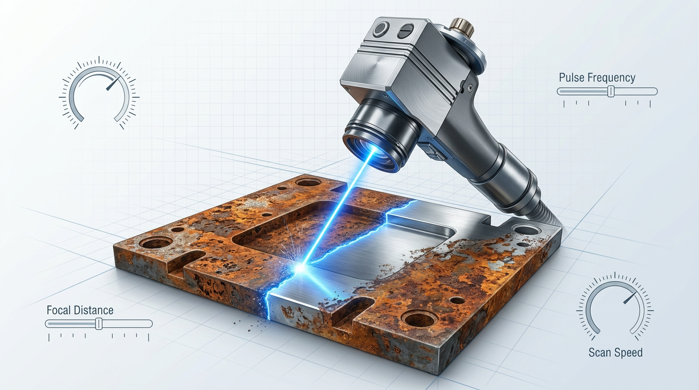
That brings in the operator's role: this process is not automatic. The operator controls four key variables — laser power, pulse frequency, scan speed, and focal distance — and those choices determine whether cleaning stays within the safe process window, above the rust ablation threshold and below the steel damage threshold.
On system type: the two main categories used for laser cleaning are pulsed laser systems and continuous-wave (CW) systems. Pulsed operation is generally preferred for rust removal, particularly on sensitive substrates, because short pulses confine heat delivery and give the operator finer control over energy input — reducing the risk of thermal damage to the substrate.
With this physical foundation in place, the procedural steps that follow are about how the operator navigates this process window in practice — beginning with assessing the surface before a single parameter is set.
Step 1
Assess the surface before you begin
Key Insights
ISO 8501-1 grade determines power level and pass count.
Identify the substrate before setting any parameters.
Set acceptance criteria before cleaning to prevent over-cleaning.
Every parameter you will set in Step 2 — power level, pulse frequency, scan speed, focal distance — is determined by what you find on the surface now, before the laser is switched on.
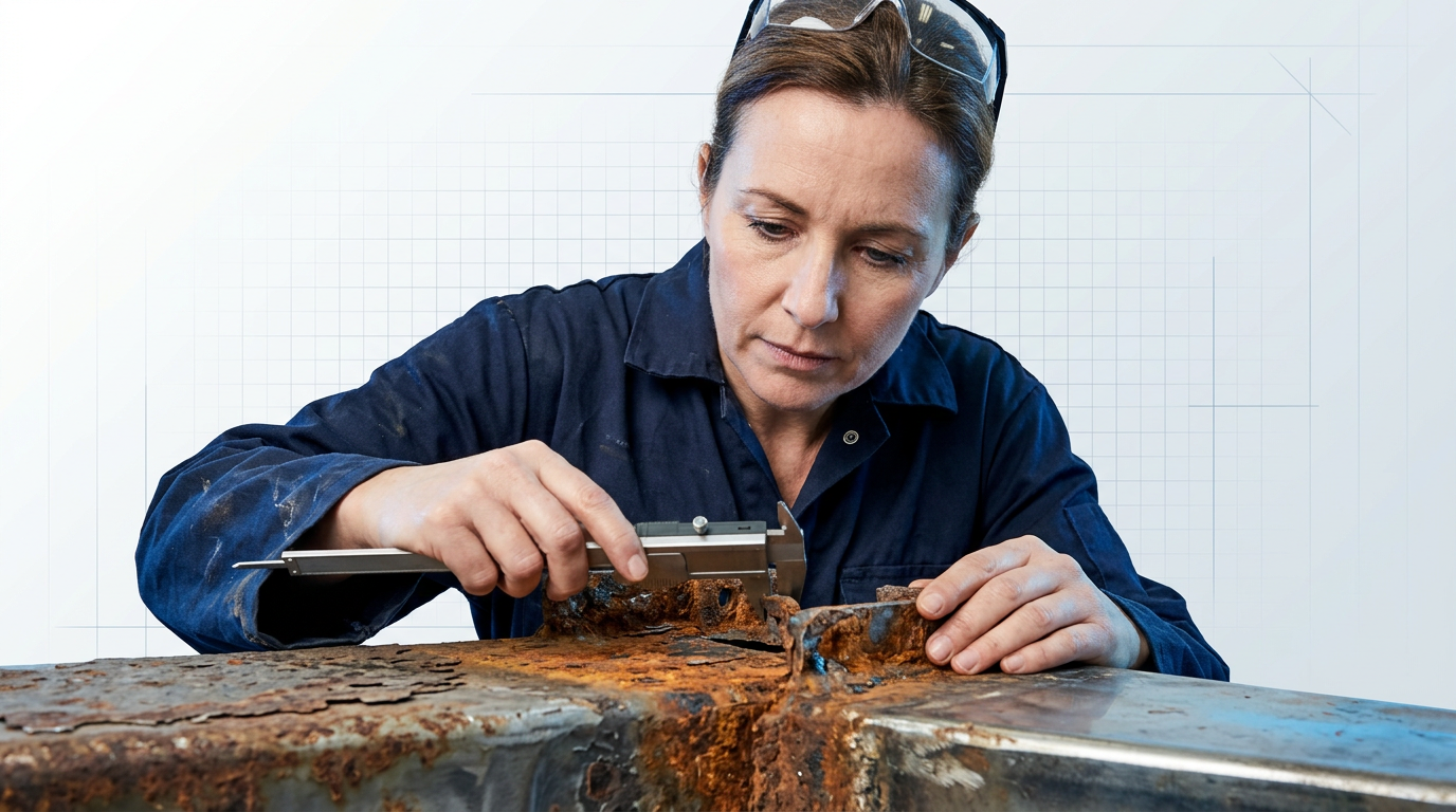
Rust thickness, substrate type, and contamination profile all shift the correct operating window for laser light rust removal; an operator who skips this step is guessing at settings that need to be grounded in evidence.
Classify the rust severity using ISO 8501-1
The ISO 8501-1 standard defines four rust grades based on visual assessment of the steel surface before any cleaning takes place — use these grades as your classification framework.
- Grade A: Steel surface largely covered with adhering mill scale, with little if any rust present. The lightest starting condition — typically requires a single pass at conservative settings.
- Grade B: Rust has begun to spread and mill scale has started to flake. Surface oxidation is active but not yet uniform. Usually one to two passes, with power adjusted upward from Grade A.
- Grade C: Mill scale has rusted away or can be scraped off; rust covers the surface but pitting is not yet significant. Expect two to four passes and closer attention to scan speed.
- Grade D: Mill scale is gone and general pitting is clearly visible. This is the most demanding starting condition — multiple passes are required, and in severe cases pre-treatment may be needed before laser cleaning.
Record the grade for the worst area on the part — ISO 8501-1 instructs assessors to log the most severe condition present, not an average.
Identify the substrate material
Identifying the substrate before touching any settings is non-negotiable: each material has a different ablation threshold and a different tolerance for thermal input.
Carbon steel is the most forgiving substrate for laser cleaning — rust and mill scale absorb laser energy far more strongly than bare steel, giving a wide and predictable process window.
Aluminium alloys combine a lower ablation threshold with high thermal expansion and high reflectivity, which together make the operating window considerably tighter than for carbon steel; conservative fluence and fast scanning are essential.
Cast iron introduces additional risk because of its graphite phase, porosity, and brittleness — rapid thermal cycling can cause micro-spalling, microcracking, and debris redeposition into pores, all of which worsen with aggressive parameters.
Check for contamination beyond rust
Rust is rarely the only material on the surface — inspect for oil, grease, paint or other coatings, and mill scale that may be layered beneath or alongside the rust.
- Oil and grease: These have different ablation characteristics from rust and may require a staged approach — a low-energy pre-treatment pass before the main rust-removal sequence.
- Paint or protective coatings: Coatings have their own absorption thresholds and may need to be treated as a separate cleaning stage from the rust beneath them.
- Mill scale beneath rust: Mill scale is harder and more adherent than red rust; its presence shifts the required fluence upward and typically increases pass count.
Each contamination layer changes the cleaning sequence — do not assume a single set of parameters will handle a mixed surface in one pass.
Flag geometric risk areas
Walk the part and mark any edges, thin sections, or areas with restricted access before you begin.
Edges concentrate heat because there is less surrounding material to conduct it away; thin sections have less thermal mass overall; and restricted-access areas may force a reduced scan speed or an inconsistent standoff distance, both of which affect energy delivery.
Note these areas now so that Step 4 can apply adjusted technique — they are not reasons to stop, but they are reasons to plan.
Decide what a successfully cleaned surface looks like for this specific application and record it before the laser runs. Continuing passes after rust is removed is one of the most common causes of substrate damage — pitting, surface roughening, and micro-structural changes all become more likely once the contaminant layer is gone and bare metal is exposed to further energy. A clear stop condition, defined in advance, prevents this. The acceptance criteria you set here also become the inspection benchmark you apply in Step 5.
By the end of this step you should have five documented inputs: rust grade, substrate type, contamination profile, geometric risk areas, and acceptance criteria — these are what you carry into Step 2.
Step 2
Select your laser parameters
Key Insights
Stay inside the process window.
Adjust scan speed before raising power.
With your surface assessment complete, every parameter you set now flows directly from what Step 1 revealed: the rust grade, the substrate type, and the contamination layers present. The task is not to maximise power or cleaning speed — it is to stay within the process window: above the energy threshold that ablates rust, below the threshold that damages the substrate beneath it.
That window is genuinely wide for most rust-on-steel combinations. Rust (Fe₂O₃) ablates at fluences roughly in the 0.1–0.5 J/cm² range, while bare carbon steel requires 5–15 J/cm² before it begins to ablate — a selectivity ratio of 10x to 150x depending on alloy and surface condition.
Power, pulse frequency, scan speed, and focal distance are all levers for staying inside a single boundary: enough energy to remove rust, not enough to harm the substrate. When cleaning is incomplete, adjust scan speed or pass count before raising power — power is the more aggressive intervention and narrows the safety buffer.
Here is how each lever works and how to set it.
The four parameters you control
Laser power governs energy delivery per unit area and sets the pace of ablation. Higher power increases both cleaning speed and ablation depth — but it also closes the gap between the cleaning threshold and the substrate damage threshold. Start conservatively and increase incrementally, using surface feedback to guide each step upward.
For most laser light rust removal applications, average power sits in the 50–300 W range. Light surface oxidation typically needs the lower end; heavily corroded surfaces with thick rust layers require more. Treat this as a starting-point orientation, not a fixed recipe.
Pulse repetition rate (frequency) controls how the laser's average power is distributed across time. Raise the frequency and the same average power is divided across more pulses per second, reducing energy per pulse. Lower the frequency and each pulse carries more energy — which thick rust layers often need, but which increases the risk of excessive heat per shot.
For sensitive substrates, a lower frequency paired with a narrower pulse width (around 100 ns) gives the best control over heat input — each pulse deposits energy and exits before significant thermal diffusion into the base material occurs. Too high a frequency may under-clean because individual pulses lack the energy to exceed the rust ablation threshold.
Scan speed determines how much energy is delivered per unit area: slower speeds concentrate the energy dose, faster speeds spread it. One practical rule: scan speed (mm/s) should be at least the product of repetition rate (Hz) and spot diameter (mm), so consecutive pulses do not land on still-warm material and cause cumulative heat buildup.
When cleaning results are incomplete, reduce scan speed — or add a pass — before raising power. Slowing the scan increases energy per unit area while keeping peak pulse intensity the same. Increasing power raises peak intensity, narrows the buffer between cleaning and damage thresholds, and makes any overshoot more abrupt.
Focal distance is the standoff between the scan head's lens and the working surface. At the correct focal distance, the beam converges to its smallest spot and highest energy density — which is what drives ablation. Even a few millimetres of drift from the qualified standoff spreads energy across a larger area and can drop fluence below the ablation threshold.
Deliberate defocus is a legitimate technique: intentionally moving the workpiece slightly outside the focal plane reduces energy density at the surface and can be used for gentle finishing passes on sensitive areas. The distinction matters — unintentional focal drift causes inconsistent results, while controlled defocus is a tool for fine-tuning fluence without touching the power setting.
CW vs. pulsed systems: what changes for parameter selection
Pulsed lasers give you independent control over pulse duration and repetition rate, allowing modulation of heat input at the pulse level — making them the preferred choice for rust removal, particularly on sensitive substrates such as aluminium or thin-gauge steel.
Continuous wave (CW) lasers deliver energy without interruption and can be effective on large structural steel components where the substrate's thermal mass is high. But because there is no pulse-level modulation, scan speed becomes the primary heat-control lever: slower speeds cause progressively greater substrate impact, while speeds above a threshold produce insufficient cleaning. The operating window is narrower and less forgiving than with pulsed systems.
If you are operating a pulsed system, set pulse duration first — shorter for heat-sensitive substrates, longer for thick rust where ablation depth per shot matters — then establish frequency and scan speed to achieve the target fluence. On a CW system, scan speed management is your primary discipline.
Staged passes for heavy rust and layered contamination
For grade C or D rust — thick, layered, or pitted corrosion — plan staged passes rather than a single aggressive run. An initial pass at higher fluence removes the bulk of the rust layer; one or more finishing passes at reduced fluence clean residual material without overexposing the now-exposed substrate.
Staging matters because the substrate's exposure changes as rust is removed. The first pass interacts almost entirely with rust; subsequent passes increasingly interact with cleaner metal. Reducing fluence on finishing passes keeps the process inside the window as the surface condition changes beneath you.
Step 3
Set up fume and particulate extraction
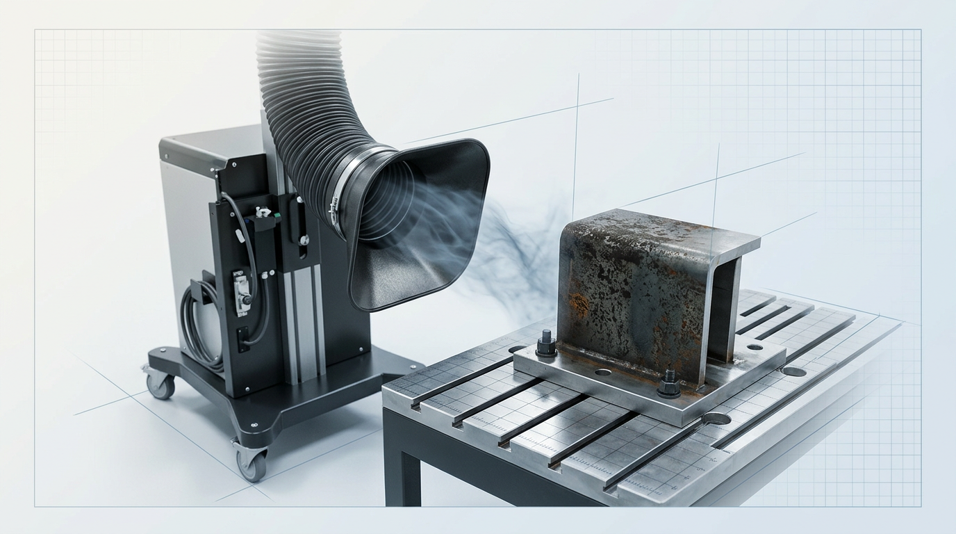
Key Insights
Confirm extraction before firing.
HEPA filtration is mandatory.
Position the hood at source.
When laser energy vaporises rust, it does not simply lift contamination away cleanly. It produces a plume of iron oxide particulates — predominantly in the nanometre range, with research on femtosecond laser ablation of steel recording particle sizes of 50–200 nm.
Particles at this scale are too small to be intercepted by the respiratory system's natural filtration. According to CDC/NIOSH particle deposition modelling, up to 90% of inhaled particles smaller than 100 nm deposit within the respiratory tract, with a significant fraction reaching the alveolar region — where the lung-blood barrier can be crossed.
This is the physical basis for treating extraction as a process requirement, not a health-and-safety addendum. The plume is generated from the moment the laser fires, and it continues throughout the cleaning pass.
The NIOSH Recommended Exposure Limit for iron oxide fume is 5 mg/m³ TWA; the OSHA Permissible Exposure Limit is 10 mg/m³. An unextracted workspace accumulates particulate in the breathing zone during operation. Confirm extraction is running before the laser fires — not after.
Under the UK Control of Substances Hazardous to Health (COSHH) Regulations, employers are legally required to prevent or adequately control exposure to substances hazardous to health. The HSE L5 Approved Code of Practice places local exhaust ventilation (LEV) above respiratory protective equipment in the hierarchy of controls — LEV is the engineering control; RPE is supplementary where residual risk remains.
The governing principle of LEV is source capture: the extraction hood must intercept the plume before it disperses into the workspace. HSG258 specifies that a capturing hood should be positioned less than one hood diameter from the source.
Positioning matters as much as airflow. If the capture point is located on the far side of the work area relative to the operator, the plume passes through the breathing zone before it reaches the hood — defeating the purpose of the system.
The extraction unit must also be capable of filtering submicron particles. Standard dust extraction is not sufficient for this application. HSG258 and BOHS technical guidance both specify that filtration of particles in the toxic range requires a HEPA filter (H13 or H14 grade) — rated at 99.95% efficiency or above for particles below 1 µm.
A system that captures the plume but recirculates air through an inadequate filter is not solving the problem — it is redistributing it. Confirm that the extraction unit fitted to your process uses HEPA filtration or equivalent before operation begins.
Pre-firing extraction check
Complete all three checks before initiating the cleaning pass. Do not begin until each is confirmed.
- Extraction unit running: Switch on the LEV unit and verify airflow is active — use the onboard airflow indicator or manometer if fitted. The unit must be running before the laser fires, not started concurrently.
- Capture point correctly positioned: Position the extraction hood within one hood diameter of the ablation zone, on the near side relative to the operator. Confirm the capture zone encompasses the working area and that no draught is deflecting the plume away from the hood.
- Filter condition within service limits: Check the filter condition indicator or pressure differential reading. If the filter is outside service limits, do not proceed. Filter servicing and replacement schedules are addressed in Step 7.
Step 4
Perform the cleaning pass
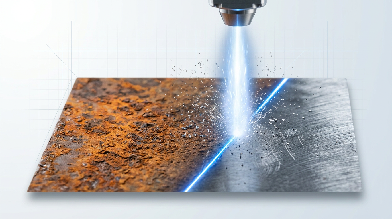
Key Insights
Run a test pass first.
Keep the beam moving — always.
With extraction confirmed and parameters set, this is where the laser fires for the first time. Before committing to the full surface, run a test pass on a corner or inconspicuous zone that matches the rust severity and substrate type you identified in Step 1.
The test pass is process validation — the same discipline as a test weld before full production. It confirms your Step 2 parameters produce clean removal without substrate discolouration, pitting, or visible heat tint, and it costs almost no time compared to the rework it prevents.
Once the test area looks correct, begin the full cleaning pass. As the scanner moves across the surface, maintain consistent standoff distance throughout — the gap between the scanner head and the workpiece directly controls where the focal point lands relative to the material.
Drift too far and the beam defocuses, delivering less energy density than needed for complete ablation. Come in too close and the concentrated fluence crosses into the substrate damage threshold. Keep the scanner at the focal distance set in Step 2 and hold it there.
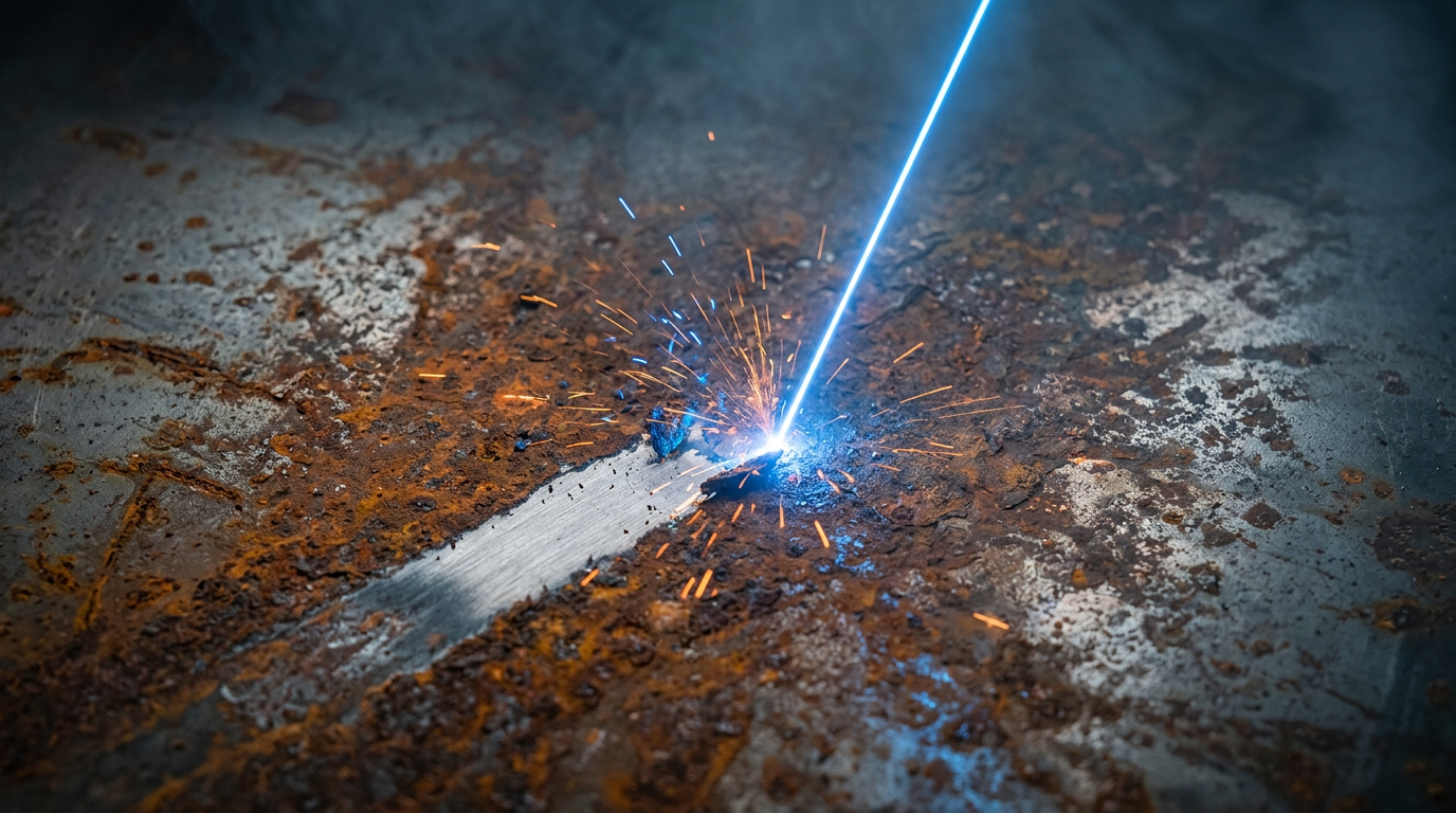
During the pass, watch the plasma plume — the visible luminous cloud that forms above the surface as laser energy vaporises the iron oxide layer. A steady plume confirms active ablation is occurring.
As the rust layer is consumed and the beam begins to approach the base metal, the plume character shifts: intensity, colour, and brightness can all change. A noticeably brighter or more intense plume at unchanged settings is a signal that the substrate is being reached, because different materials emit different plasma spectra. Treat this as a useful guide, not a precise instrument — plume reading is a skill you develop with experience.
The primary completion cue is surface colour, not the plume. Rust-covered steel presents as orange-brown; as the iron oxide layer is removed, the surface transitions to a clean metallic grey. When additional passes produce no further colour change and the surface has reached a uniform metallic appearance, the cleaning threshold has been met.
That colour-change endpoint maps directly to the acceptance criteria you set in Step 1 — stop when the surface matches what you defined as the target condition, not before and not after.
Continuous scanner movement is non-negotiable. Stopping or even slowing the scan concentrates laser energy in one spot, raising local fluence above the substrate damage threshold and causing pitting, discolouration, or material loss. This is the single most common cause of substrate damage in handheld operation. The beam must keep moving — always.
For surfaces you assessed as Grade C or D in Step 1, expect to make multiple passes rather than achieving full removal in one sweep.
After each pass, pause and assess the surface before continuing. Staged cleaning limits cumulative heat accumulation in the substrate and gives you a natural checkpoint to verify progress and adjust parameters if the surface is responding differently than expected.
- Pass and assess: After each pass on a heavily rusted area, stop and examine the surface before running the next. Do not stack passes continuously without checking progress.
- Let the surface cool between passes: Multiple rapid passes accumulate heat in the substrate. Brief pauses between passes keep the thermal load within safe limits for the base material.
- Adjust if the surface responds unexpectedly: If colour change is slower than expected or heat tint appears, use the pause between passes to revisit scan speed before adding more power.
Throughout every pass, spatter and debris ejected from the surface are normal — they confirm that ablation is occurring, not a sign that something is wrong.
That debris generation is continuous, which is why the extraction system set up in Step 3 must remain active for the entire duration of the cleaning pass, not just at start-up.
Once the surface has reached a uniform metallic appearance and further passes produce no additional colour change, the cleaning pass is complete. The surface is ready for formal inspection in Step 5.
See the machines built for this process
Understanding the process is step one. The right machine makes it repeatable. Explore the ELASER laser cleaning range and see how each system is built for controlled, precise rust removal.
Step 5
Inspect the cleaned surface
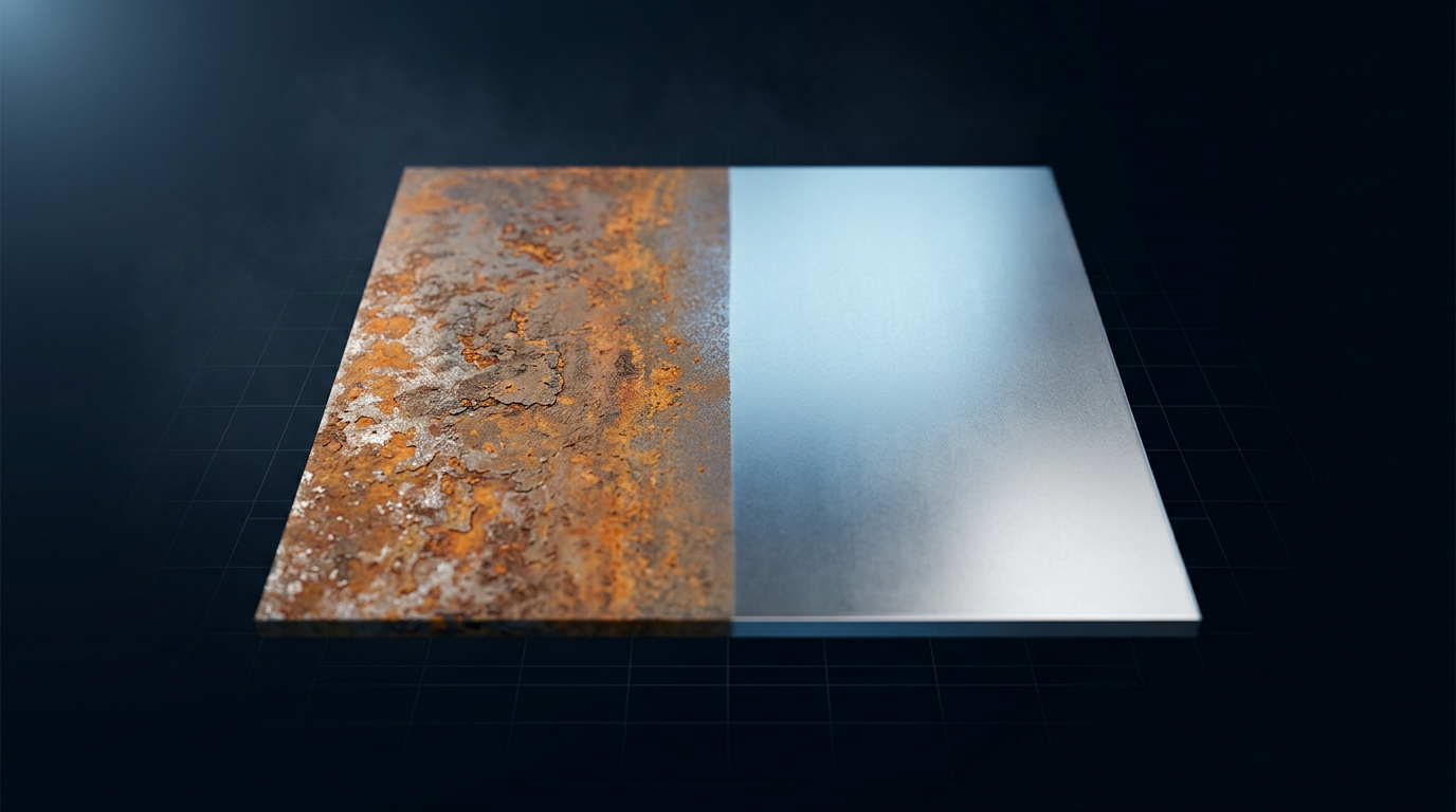
Key Insights
Staining means more passes; pitting means adjust parameters.
Sa 2½ and Sa 3 are your benchmarks.
Inspect the surface visually first — this is the baseline check every operator performs, regardless of how critical the application is.
A correctly cleaned surface has a uniform metallic appearance: no orange-brown rust staining, no residual scale, and no dark discolouration that would suggest localised overheating during the pass.
Use ISO 8501-1 preparation grades as your cleanliness benchmark — this is the industry-standard framework for specifying and verifying surface cleanliness outcomes, particularly when the cleaned surface will be handed off to a coating or bonding process.
Sa 2½ (very thorough cleaning, equivalent to near-white metal) is the most common target for coating preparation; Sa 3 (white metal — visually clean steel with no visible rust, scale, or contamination) is required for the most demanding applications. Correctly parameterised laser cleaning is capable of achieving both.
Signs of incomplete cleaning
If you see any of the following, the cleaning pass has not fully achieved its objective — run additional passes before proceeding.
- Residual rust staining: Orange or brown discolouration remaining on the surface after the pass — the most obvious signal that the rust layer has not been fully ablated.
- Patchy or non-uniform metallic appearance: Areas of clean metal interspersed with dull or discoloured patches, indicating uneven coverage or insufficient overlap between scan lines.
- Unchanged surface texture: Sections where the surface looks and feels the same as the pre-clean condition — the beam did not dwell long enough, or the fluence was insufficient for the rust thickness present.
These are all signals that more work is needed — not that something has gone wrong with the process or the parameters.
Signs of substrate damage
Substrate damage signals are categorically different from incomplete-cleaning signals: they indicate the process window was exceeded and the base material itself has been affected.
- Pitting or micro-cratering: Small depressions in the surface where the base metal has been removed rather than just the rust layer — a clear sign the fluence exceeded the substrate's ablation threshold.
- Heat tint: A blue-gold iridescent discolouration caused by localised overheating of the substrate. This is distinct from rust staining and indicates thermally induced oxidation of the base metal, not residual contamination.
- Roughened texture beyond pre-clean baseline: Surface roughness noticeably greater than the surrounding unaffected metal, suggesting the beam has begun ablating into the substrate rather than stopping at the rust interface.
If you see any of these signals, stop and revisit your parameters — as covered in Step 2 — before continuing. More passes will not fix substrate damage; they will compound it.
Advanced inspection for critical applications
For aerospace components, fatigue-critical parts, or surfaces going into a structural weld or bond, visual inspection alone is not sufficient.
- Surface profilometry (Ra/Rz measurement): Quantifies surface roughness to confirm it falls within the specification required by the downstream process — coating, bonding, or welding each have their own acceptable range.
- Vickers microhardness testing: Rules out thermally induced changes to the substrate's mechanical properties. A significant drop or rise in hardness relative to the parent material indicates heat-affected zone formation.
- Dye-penetrant inspection (DPI): Reveals surface-breaking cracks on sensitive substrates that would not be visible to the naked eye. Particularly relevant for high-strength steels and thin-section components.
These methods are tools for critical applications — not routine requirements for every job. Know they exist, and reach for them when the downstream process or component service life demands certainty beyond what the eye can provide.
Over-cleaning is a leading cause of substrate damage. Once the rust is fully removed, the beam begins interacting with clean base metal rather than the rust it was tuned to ablate — further passes at that point risk pitting and heat tint, not a cleaner surface. The acceptance criteria you defined in Step 1 are your stop condition: when the surface meets the required preparation grade and shows no damage signals, the job is done.
Step 6
Adapt your approach for different substrates and rust grades
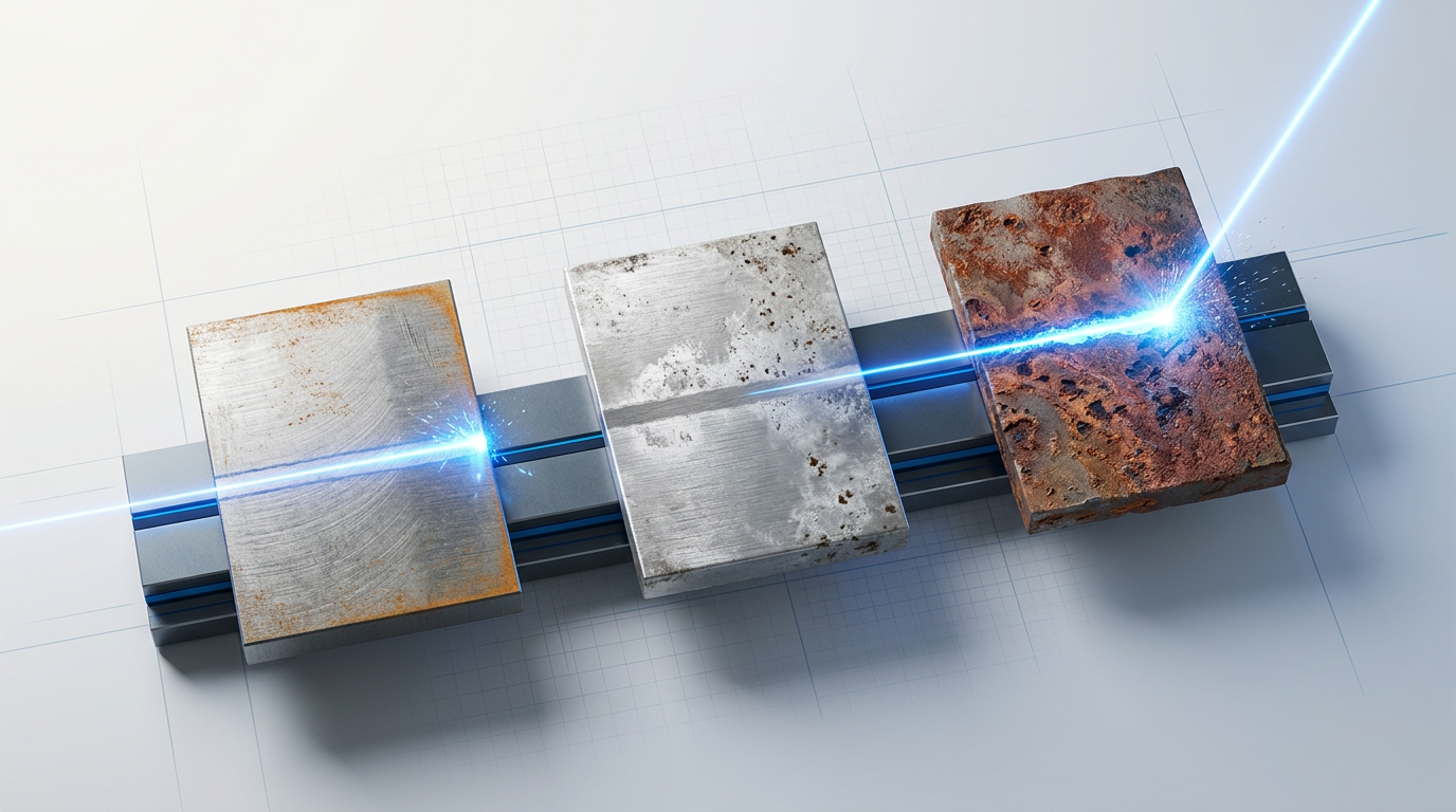
Key Insights
Aluminium needs shorter pulses, lower fluence.
Use staged passes for heavy rust.
The parameter set you validated in Steps 1–4 is a starting point, not a universal recipe. Every substrate and rust severity regime shifts the process window, and knowing which direction to move your levers — before you encounter a problem on the surface — is what separates confident operators from those who over-clean or under-clean.
Light surface oxidation (ISO Grade A/B)
Grade A/B oxidation is the widest process window you will encounter: lower power and faster scan speeds are sufficient, and substrate risk is low.
If you are new to laser cleaning, start here. Grade A/B surfaces let you build confidence reading the surface response — the colour shift, texture change, and plume behaviour — before you move to more demanding conditions.
Heavy rust and pitting (ISO Grade C/D)
Grade C/D rust requires more energy per unit area, but resist the instinct to deliver it in a single aggressive pass. A first pass removes bulk rust; follow with one or more passes at reduced fluence to clear residual material.
The staged approach limits heat accumulation and gives you an inspection checkpoint between each pass — use the surface assessment from Step 5 to decide whether another pass is warranted before committing.
Carbon and low-alloy steel
Carbon and low-alloy steel is the most forgiving substrate, with the widest operating window of the three materials covered here.
Research on pulsed fiber laser rust removal gives illustrative parameter ranges for this substrate: pulse durations of 50–150 ns, fluence in the 1.0–4.0 J/cm² range, and scan speeds of 2,000–8,000 mm/s. Treat these as a starting reference — your test pass from Step 4 remains the validation mechanism, not this table.
Aluminium alloys
Aluminium has a lower ablation threshold than steel, which means the margin between cleaning and substrate damage is considerably narrower. The process window for Al₂O₃ over aluminium is classified as narrow — roughly 1–3× selectivity versus the 16–150× ratio typical for Fe₂O₃ over carbon steel.
Use shorter pulse durations (10–80 ns) and conservative fluence (0.3–1.5 J/cm²) with faster scan speeds. On fatigue-critical parts — aerospace fittings, structural brackets — check specifically for recast layer formation: melt that resolidifies on the surface rather than ablating cleanly is a genuine structural risk on these components.
Always run a careful test pass on aluminium before committing to the full surface. The absorption behaviour can shift as the oxide layer is removed, making the process less predictable than steel mid-clean.
Cast iron
Cast iron is more sensitive than its often-heavy corrosion suggests. Its brittle microstructure makes it susceptible to micro-spalling and microcracking from thermal shock — graphite phases in the matrix act as nucleation sites for crack initiation and propagation under rapid thermal cycling.
Use gentler parameters and lower beam overlap than you would on carbon steel. Keep extraction discipline high throughout: cast iron's graphite-rich pores trap ablated debris if extraction is inadequate, contaminating the cleaned surface and interfering with any subsequent coating.
| Condition / Substrate | Pulse Duration | Fluence (J/cm²) | Scan Speed | Key Risk / Note |
|---|---|---|---|---|
| Light oxidation — Grade A/B | 50–150 ns | 1.0–2.0 | Faster end of range | Wide process window; low substrate risk |
| Heavy rust / pitting — Grade C/D | 50–150 ns | 2.0–4.0 (first pass); reduce on follow-up passes | Slower for bulk removal | Heat accumulation; use staged passes |
| Carbon / low-alloy steel | 50–150 ns | 1.0–4.0 | 2,000–8,000 mm/s | Most forgiving substrate; widest window |
| Aluminium alloys | 10–80 ns | 0.3–1.5 | Faster than steel | Narrow process window; recast layer risk on fatigue-critical parts |
| Cast iron | Shorter / gentler | Conservative — stay well below steel values | Lower overlap | Micro-spalling, microcracking, pore contamination from debris |
Gives operators and evaluators a fast substrate-by-substrate reference for the parameter adjustments discussed in the preceding body paragraphs. Rows cover the three substrate types plus the two rust severity regimes; columns show the key adjustable parameters and the primary risk to manage.
The table above gives directional starting points. Your test pass is always the final arbiter — no reference table substitutes for reading your actual surface response.
Mixed contamination: rust over paint or mill scale
Layered contamination is the most dynamic scenario: as each layer is removed, the absorption behaviour and cleaning threshold of the surface beneath it change. Parameters that ablate the outer rust layer cleanly may be too aggressive — or too conservative — for what lies underneath.
Plan staged passes from the outset and reassess between each one. You are running a micro-cycle of clean, inspect, and adjust for every layer — exactly the pattern established in Steps 4 and 5, applied repeatedly as the surface condition evolves.
Staged passes are the safer approach for any condition where you are uncertain — heavy rust, sensitive substrates, mixed contamination. A first pass at conservative fluence removes bulk material and reveals what lies beneath. Subsequent passes at adjusted parameters clean residual material without overexposing the substrate.
Step 7
Maintain your laser cleaning system

Key Insights
Inspect the protective window every session.
Never touch optics with bare fingers.
A damaged end-face can destroy the laser.
Degraded beam despite clean optics? Escalate.
With the cleaning sequence complete, the habits you build between sessions are what keep your laser light rust removal system performing at specification — and the good news is that the maintenance burden is genuinely light.
Protective Window: Inspect and Replace Regularly
Inspect the protective window before or after every session — it sits directly between the focusing optic and the work surface, absorbing spatter and fume deposition so the lens behind it does not have to.
Replace it as soon as visible contamination appears or when beam quality seems to have dropped: a dirty window reduces energy density at the working surface and, left unchecked, risks heat damage to the focusing lens it is protecting.
Optical Surfaces: Clean Correctly or Not at All
When cleaning any optical surface, use optical-grade materials only: lint-free lens tissue and isopropyl alcohol or an equivalent optical solvent.
Always inspect the surface before touching it, start with a dry technique, and progress to a wet technique only if dry cleaning is insufficient — and never touch an optical surface with bare fingers, as skin oils contaminate coatings and the damage is harder to fix than the original contamination.
Delivery Cable: Handle With Discipline
The fibre delivery cable is the most mechanically vulnerable component in the system: avoid tight bends and kinking, never run equipment over it, and do not allow it to be pinched.
Inspect the connector end-face before each session and clean it if contaminated. A damaged end-face degrades beam quality — and in severe cases can destroy the laser source itself. With cable runs up to 50 m, there is more opportunity for mechanical abuse, which makes disciplined handling habits more important, not less.
Coil the cable loosely when storing it and never leave it under tension or across a walkway where it can be stepped on or driven over.
Pre-Session Checks: Run This Before Every Job
Run through this checklist at the start of each session — it takes under two minutes and catches the conditions most likely to cause a poor result or a system issue.
- Confirm extraction is operational: The LEV unit must be running before the laser fires — as established in Step 3.
- Verify focal distance: Confirm the scanner is set to the correct working distance for this job before starting.
- Inspect and seat the cable connector: Check the connector end-face is clean and correctly seated before powering up.
- Confirm power settings: Verify that parameters match the validated process settings for this job — as established in Step 2.
- Inspect the protective window: If you have not already checked it post-session, inspect it now and replace if needed.
This loop is not a re-teaching of earlier steps — it is a confirmation that the conditions those steps established are still in place before you fire the laser.
Maintenance Costs in Context
The primary consumables for a laser cleaning system are protective windows and periodic connector cleaning materials — both predictable and low-cost.
There are no abrasive media to replenish, no chemicals to dispose of, and no water circuits to maintain: the total cost of ownership picture for laser light rust removal is genuinely favourable compared to abrasive and chemical alternatives, and that advantage compounds over time.
When to Escalate to the Manufacturer
Most maintenance is well within operator capability — but know the signals that require qualified service rather than further adjustment.
- Beam quality degrades despite clean optics and a clean connector: This points to an internal component issue. Do not attempt to compensate by adjusting power or scan parameters — escalate.
- Unexpected power fluctuations: Inconsistent output that cannot be traced to a dirty window or connector is a service-level fault.
- Scanner behaviour changes: Any change in scan pattern, speed response, or audible scanner behaviour warrants a call to the manufacturer.
These situations are the rare exception to an otherwise manageable routine — but when they occur, contact the manufacturer rather than investigating internally.
Ready to put the process into practice?
You now understand the full laser light rust removal process. The next step is finding the right machine for your application. Book a call with a laser cleaning expert to discuss your requirements.
Conclusion
What you can do now
Laser light rust removal is a precise, controllable process — and what makes it reliable is not the hardware alone, but the operator's understanding of why each variable matters: the physics of selective absorption, the discipline of staying within the process window, the non-negotiable role of extraction, and the habit of inspecting before moving on.
From here, the natural directions are formal operator training, a closer evaluation of whether laser cleaning suits your specific application, or a conversation with a manufacturer about your requirements — whichever fits where you are now.
Frequently asked questions about laser light rust removal
Common questions about how laser light rust removal works, what it can handle, and what operators need to know before they start.
Yes — rust removing lasers work, and the physics explain precisely why. Iron oxides such as Fe₂O₃ and Fe₃O₄ absorb laser energy far more readily than clean steel beneath them. This selectivity means the laser vaporises the rust layer while leaving the substrate untouched — not by luck, but by design. Published research confirms the outcome in measurable terms: surface iron (Fe) content rises from approximately 62% before cleaning to over 90% after laser cleaning, while oxygen content drops from around 29% to just 2–3%. That shift in elemental composition is direct evidence that the iron oxide layer has been removed and the underlying metal exposed. Angle grinding, by comparison, leaves Fe content at roughly 68% — demonstrating that laser cleaning achieves more thorough rust removal than mechanical abrasion.
Laser rust removal has real trade-offs that any informed evaluator should weigh. The process is not plug-and-play: it requires trained operators who understand parameter selection, and incorrect settings — excessive power, too-slow scan speed, wrong focal distance — can damage the substrate or leave incomplete cleaning. On very large surface areas, it is slower than abrasive blasting, which moves faster across open structural steel. Upfront system cost is higher than manual or chemical methods; this is a genuine category-level consideration, not a minor footnote. Fume and particulate extraction is non-negotiable — vaporised rust generates iron oxide particles and potentially toxic fumes, so a properly specified local exhaust ventilation system with HEPA filtration is required before the laser fires, adding to setup overhead. Finally, the process window is tighter on sensitive substrates such as aluminium, where the margin between effective cleaning and substrate damage is narrower than on carbon steel, requiring more conservative parameter control. None of these are fatal flaws — but they are real factors in a fair assessment.
Pulsed fibre lasers operating at 1064 nm are the preferred choice for industrial rust removal. At this wavelength, rust and iron oxides absorb laser energy efficiently while clean steel reflects more of it — a natural selectivity that underpins the whole process. Pulsed operation gives operators finer control over heat input than continuous wave (CW) systems. Because each pulse removes a thin layer with minimal heat transfer to the substrate, pulsed lasers are generally preferred, especially on sensitive or precision parts. CW fibre lasers can be effective on large structural steel components where heat dissipates quickly and substrate damage tolerance is higher — but they carry a greater risk of thermal effects if scan speed is not carefully managed. On power: approximately 50 W is sufficient for precision or light-rust work; industrial-scale rust removal on heavily corroded surfaces typically calls for 300 W or more. Systems range widely, with high-power units reaching 1,000 W and above for demanding applications.
Properly parameterised laser cleaning does not damage the substrate — and the reason is grounded in a wide physical selectivity window. The ablation threshold for rust (loose Fe₂O₃) typically falls between 0.1 and 0.5 J/cm². Bare carbon steel does not begin to ablate until fluence reaches 5–15 J/cm². That gap — a selectivity ratio of 10x to 150x depending on alloy and surface condition — is what makes the process inherently safe for the base material when operated correctly. Damage occurs only when the operator steps outside the process window: typically through excessive power, scan speed that is too slow (allowing heat to accumulate), or incorrect focal distance. Multiple independent studies using Vickers hardness cross-sections confirm no statistically significant hardness change in the substrate heat-affected zone when pulse durations remain under 200 ns and fluence stays within the selectivity window. The practical conclusion: substrate damage is a parameter control problem, not an inherent limitation of the technology.
The primary cue is surface colour change. Rust-covered steel transitions from orange-brown to a uniform metallic grey as the iron oxide layer is removed. When further passes produce no additional colour change, the cleaning threshold has been reached. For most applications, this visual check is sufficient — but it should be benchmarked against a recognised standard. ISO 8501-1 provides the accepted visual classification for steel surface cleanliness, defined by written descriptions and photographic references. Sa 2½ (near-white metal, with no more than 5% staining allowable per unit area) is the most common target for coating preparation. Sa 3 (white metal — completely free of all visible rust, scale, and foreign matter) applies to the most demanding applications. For critical components where visual inspection alone is not sufficient, surface profilometry (Ra and Rz roughness measurement) and Vickers microhardness testing provide confirmatory checks that the cleaning has been effective without introducing substrate damage.
Yes — laser cleaning can remove surface oxidation from aluminium, but the operating window is tighter than for carbon steel. Aluminium has a lower ablation threshold than steel (typically 3–8 J/cm² for the substrate itself, compared to 5–15 J/cm² for carbon steel), which means the margin between effective cleaning and unintended substrate damage is narrower. In practice, this calls for shorter pulse durations (ideally below 80 ns), more conservative fluence settings, and faster scan speeds compared to steel. Aluminium also combines low melting point with high thermal expansion and surface reflectivity, which together make parameter errors more consequential. The process is routinely done in industrial settings — but it demands more careful parameter development. Running a structured test pass on a representative coupon before committing to production parts is strongly advisable, both to establish the cleaning threshold and to confirm the damage threshold margin for the specific alloy and surface condition.