


Introduction
If you are specifying components for an optical network, designing amplifier stages for a WDM system, or evaluating pump sources for submarine cable infrastructure, this guide is written for you.
It works through the decisions that actually shape an amplifier's performance: how your choice of pump wavelength propagates through noise and gain budgets, how packaging format determines your integration path, how thermal strategy affects long-term reliability, and what compliance evidence you should expect from a vendor before committing.
The underlying argument running through all of it is that an EDFA pump laser is not a commodity line item — it is a foundational design decision, and the right choice only becomes clear when you reason about the whole amplifier.
TL;DR
Pump laser selection is inseparable from amplifier performance. The wavelength you choose sets your noise floor, your packaging format determines your integration constraints, and your thermal strategy defines the reliability ceiling. Every one of these decisions connects — which means getting any one of them wrong compounds through the rest of your design.
This article covers:

980 nm vs 1480 nm wavelength trade-offs
Packaging formats and integration implications
Thermal management strategies and their trade-offs
How pump power affects gain and noise
Wavelength stability and FBG stabilisation
Compliance standards as procurement considerations
What Is an EDFA Pump Laser?
The pump wavelengths used in an erbium-doped fibre amplifier — 980 nm or 1480 nm — sit hundreds of nanometres away from the signals they amplify, which travel in the 1530–1565 nm C-band. That gap is not incidental: it is a direct consequence of the energy-level physics of erbium ions, and understanding it is the key to understanding every specification decision that follows.
An EDFA pump laser is a high-power semiconductor laser diode whose sole function is to supply the optical energy that drives gain in an erbium-doped fibre amplifier. It operates at either 980 nm or 1480 nm — the two wavelengths at which erbium ions absorb pump photons efficiently — and it is the component that determines whether the amplifier produces gain at all.
The Pump Laser Within the EDFA Structure
An EDFA is built from a small number of precisely coordinated components, each with a defined role in the amplification process.
- Pump laser diode: The optical energy source. Injects high-power pump light at 980 nm or 1480 nm into the amplifier chain.
- Erbium-doped fibre (EDF): The gain medium. A silica fibre whose core is doped with trivalent erbium ions (Er³⁺) that absorb pump photons and amplify signal light.
- WDM coupler: A wavelength-division multiplexing coupler that combines the pump and signal wavelengths into a single fibre path entering the EDF.
- Optical isolators: Placed at the input and output to block back-reflections that would otherwise destabilise the amplifier or degrade noise performance.
The pump laser feeds into the WDM coupler, which merges the pump light with the incoming signal before both enter the erbium-doped fibre. What happens inside that fibre is determined almost entirely by the pump laser's output.
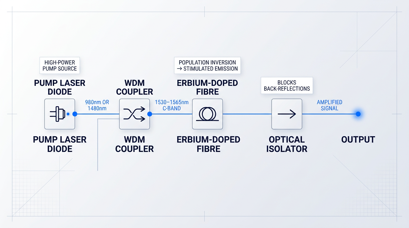
Understanding the structure makes one thing clear: the pump laser is not a peripheral support component. Every other element in the chain — the EDF, the coupler, the isolators — is passive without it.
How Pump Photons Produce Optical Gain
The gain mechanism in an EDFA is rooted in the energy-level behaviour of trivalent erbium ions (Er³⁺) embedded in the silica fibre core. When pump photons enter the doped fibre, they are absorbed by Er³⁺ ions sitting in the ground-state manifold (⁴I₁₅/₂), exciting them to a higher energy level.
From that higher level, the excited ions decay rapidly and non-radiatively into a metastable energy level designated ⁴I₁₃/₂ — the upper laser level. The key property of this level is its lifetime: ions remain there for approximately 10 ms, which is roughly four orders of magnitude longer than the lifetime of the intermediate pump level above it.
With continuous pump power, Er³⁺ ions accumulate in the ⁴I₁₃/₂ state faster than they leave it. When a signal photon in the 1530–1565 nm C-band passes through the fibre and encounters an ion in this metastable state, it triggers stimulated emission: the ion releases a second photon at exactly the same wavelength, phase, and direction as the signal photon. That is the amplification event.
Amplification only occurs when more Er³⁺ ions occupy the metastable ⁴I₁₃/₂ state than the ground state — a condition called population inversion. Without sufficient pump power to achieve and sustain this, the erbium-doped fibre absorbs the signal rather than amplifying it. The pump laser is what creates and maintains population inversion; remove it, and the amplifier becomes an attenuator.
This dependence on population inversion is why pump laser specifications are not interchangeable with system requirements. Power output, wavelength accuracy, and stability all directly determine whether inversion is achieved, how completely it is sustained, and therefore what gain and noise figure the amplifier delivers.
Two Pump Wavelengths, Two Energy Pathways
The two dominant pump wavelengths — 980 nm and 1480 nm — each produce population inversion in the ⁴I₁₃/₂ state, but via distinct energy-level pathways.
980 nm pumping follows a three-level scheme. Pump photons excite Er³⁺ ions from the ground state (⁴I₁₅/₂) to a short-lived intermediate level (⁴I₁₁/₂), which has a lifetime of only around 1 µs. From there, the ions decay non-radiatively into the metastable ⁴I₁₃/₂ level. Because the intermediate level empties so rapidly, virtually all excited ions accumulate in the metastable state, producing a high degree of population inversion.
1480 nm pumping follows a two-level-like scheme. Pump photons at this wavelength correspond to the energy gap between the ground-state manifold and the upper manifold of the ⁴I₁₃/₂ state itself, so they excite Er³⁺ ions directly into the metastable level, bypassing the intermediate step entirely. Because the pump and signal transitions share the same pair of energy levels, population inversion is inherently incomplete.
Both schemes produce gain in the C-band (1530–1565 nm), where erbium's stimulated emission cross-section is highest. With appropriate fibre design and pumping, the gain window can also be extended into the L-band (1565–1625 nm). The practical consequences of choosing between 980 nm and 1480 nm — for noise figure, gain efficiency, and application fit — are the subject of the next section.
With the gain mechanism and the two pumping schemes established, the most consequential decision in pump laser selection comes into focus: which wavelength to use, and what that choice means for every performance metric the amplifier must meet.
980 nm vs 1480 nm: Choosing the Right Pump Wavelength
Selecting a pump wavelength for an EDFA is not a component preference — it is a system-level commitment that propagates through every downstream design decision: noise figure budget, gain per unit fibre length, thermal management complexity, wavelength stabilisation requirements, and ultimately which applications the amplifier can serve.
Both 980 nm and 1480 nm are well-established, commercially mature pump wavelengths for erbium-doped fibre amplifiers, and each is unambiguously the right choice in its appropriate context — the engineering task is knowing which context you are in.
Gain Efficiency and Noise Figure: Where 980 nm Leads
Because 980 nm pumping drives erbium ions through the short-lived ⁴I₁₁/₂ level before they settle into the metastable ⁴I₁₃/₂ state, there is essentially no stimulated emission by the pump wave itself — near-complete population inversion is achievable.
This translates directly into the highest gain efficiency of any standard EDFA pump scheme: RP Photonics places 980 nm gain efficiency on the order of 10 dB/mW, substantially higher than what 1480 nm pumping can achieve for the same signal wavelength.
The noise figure advantage follows from the same physics: because 1480 nm pumping excites erbium directly into the upper manifold of ⁴I₁₃/₂, where absorption and emission bands overlap, complete population inversion is physically impossible at that pump wavelength.
That overlap is not a design limitation to be engineered around — it is a fundamental constraint of the 1480 nm pumping scheme, and it imposes an unavoidable noise penalty relative to 980 nm.
980 nm pumping approaches the 3 dB quantum limit for noise figure because near-complete population inversion is achievable. 1480 nm pumping cannot reach this limit — the overlapping absorption and emission bands at that wavelength make incomplete inversion a physical constraint, not a design choice.
Power Conversion Efficiency: Where 1480 nm Leads
The clearest advantage of 1480 nm pumping is its smaller quantum defect: the energy gap between a 1480 nm pump photon and a 1530–1565 nm signal photon is much smaller than the gap between a 980 nm pump photon and the same signal.
That energy difference is dissipated as heat for every signal photon generated, so the smaller the gap, the more efficiently pump power converts into signal output power — and the lower the thermal burden on the amplifier module.
Lightwave Online quantifies the scale of this difference: converting a 980 nm photon to 1550 nm is approximately 50% less power-efficient than using a 1480 nm photon for the same conversion, which is why 1480 nm is the preferred pump wavelength wherever output power per unit cost is the binding constraint.
1480 nm-pumped amplifiers also exhibit a higher gain saturation point than their 980 nm counterparts, meaning they can handle larger input signal powers before gain begins to compress — a critical property for booster-stage and high input power applications.
EDF Length: A Co-variable in Wavelength Selection
The gain advantage of 980 nm pumping is not universal across all EDF lengths: published academic data confirms that 980 nm pumping produces higher gain than 1480 nm for fibre lengths up to approximately 5 m, but for longer fibres the relationship reverses.
This means EDF length is a co-variable in wavelength selection — an engineer cannot fix the pump wavelength without also fixing, or at least constraining, the intended fibre length, and vice versa.
Wavelength Stability: A Downstream Design Consequence
The erbium absorption spectrum around 980 nm is sharply peaked: even small wavelength shifts in the pump diode materially degrade absorption efficiency, which in turn affects gain and noise figure — particularly in multi-pump DWDM configurations where pump-to-pump spectral consistency matters.
As a result, 980 nm pumps for complex EDFAs typically require external FBG stabilisation to lock the emission wavelength within the absorption peak; the broader, more gradually varying erbium absorption spectrum around 1480 nm generally eliminates this need, reducing cost and system complexity in high-power booster stages.
The wavelength stabilisation requirement for 980 nm also connects to thermal management: TEC-cooled pump configurations are partly motivated by the need to hold the diode junction temperature — and therefore its emission wavelength — within a tight window. (That relationship is explored in the thermal management section.)
Comparing the Two Pump Wavelengths
The table below summarises the key engineering trade-offs across the dimensions that matter most to system designers specifying an EDFA pump laser.
| Parameter | 980 nm Pumping | 1480 nm Pumping |
|---|---|---|
| Gain efficiency | ~10 dB/mW (order of magnitude; highest achievable with standard pumping) | Lower than 980 nm for same signal wavelength; higher pump power needed for equivalent small-signal gain |
| Noise figure | Approaches 3 dB quantum limit; near-complete population inversion achievable | Unavoidably higher; incomplete inversion is a physical constraint of the pumping scheme |
| Power conversion efficiency | Lower; larger quantum defect (~980 nm to ~1550 nm energy gap dissipated as heat) | Higher; ~50% more power-efficient per photon conversion than 980 nm pumping |
| Wavelength stability requirement | FBG stabilisation typically required; sharply peaked absorption spectrum is sensitive to drift | Generally not required; broader, more gradual absorption spectrum tolerates wavelength variation |
| EDF length dependency | Higher gain than 1480 nm for EDF lengths up to ~5 m | Higher gain than 980 nm for EDF lengths beyond ~5 m |
| Gain saturation point | Lower saturation point; less suited to high input signal power scenarios | Higher saturation point; better suited to large input signal powers |
| Primary application | Low-noise preamplifier stages, metro DWDM, noise-figure-constrained systems | High-power booster stages, remotely pumped amplifiers, submarine cable systems |
Side-by-side comparison of 980 nm and 1480 nm EDFA pump wavelengths across the seven engineering axes that determine amplifier design and application suitability.
Reading this table in the context of your system design, the key pattern is that the two wavelengths are not competing on the same axis: 980 nm wins on noise figure and gain efficiency per milliwatt of pump power, while 1480 nm wins on power conversion efficiency, saturation headroom, and wavelength stability simplicity.
If your system's binding constraint is noise figure — a preamplifier stage receiving a weak signal, or a DWDM network where noise accumulates across cascaded amplifiers — 980 nm is the correct choice, and the added complexity of FBG stabilisation is the cost of that performance.
If your binding constraint is output power per unit cost, or if the pump laser must deliver light over a significant fibre length to a remotely located amplifier (where 1480 nm experiences lower transmission loss than 980 nm through standard silica fibre), 1480 nm is the appropriate selection.
The EDF length dependency deserves particular attention: engineers who specify a 980 nm pump for a long-fibre configuration — or a 1480 nm pump for a short, low-noise stage — are working against the physics of their chosen wavelength, not with it.
Application Mapping: Which Wavelength Fits Which Role
- 980 nm: Preamplifier stages: Co-propagating 980 nm pumping minimises noise figure, making it the clear choice where weak input signals must be amplified cleanly.
- 980 nm: Metro DWDM networks: Reduced power consumption and lower heat generation suit central-office environments where thermal and electrical budgets are constrained.
- 980 nm: Noise-figure-critical systems: Wherever cascaded amplifiers accumulate noise — long-haul chains, narrow channel spacing — the 3 dB quantum limit proximity of 980 nm is decisive.
- 1480 nm: Booster and output stages: Higher power conversion efficiency and a higher saturation point make 1480 nm the preferred pump where maximising launched signal power is the objective.
- 1480 nm: Remotely pumped amplifiers: Lower transmission loss at 1480 nm through standard silica fibre allows the pump laser to be located remotely from the amplifier — essential in submarine and distributed systems.
- 1480 nm: Submarine cable systems: High output power requirements and the remote pumping architecture of submarine links make 1480 nm the established choice for undersea amplifier stages.
In practice, many high-performance EDFA designs exploit both wavelengths across different stages — but that architecture is a downstream consequence of understanding this trade-off clearly, not a way to avoid making the decision.
With the wavelength decision framed, the next practical question is how the pump laser is physically packaged and integrated into the amplifier module — the subject of the following section.
Pump laser packaging formats: butterfly, mini-DIL, and microformat
Once wavelength is chosen, the next decision that shapes your entire integration path is packaging format — and it is not a mechanical afterthought.
The package determines whether a thermoelectric cooler (TEC) is present, how much board real estate the module occupies, what heat sink geometry is required, and how the module will behave across years of thermal cycling in the field.
Four principal formats are in common use for EDFA pump lasers: the 14-pin butterfly, the 10-pin mini-butterfly (mini-BTF), the 8-pin mini-DIL, and the ultra-compact 3-pin microformat.
Each represents a distinct design philosophy — not merely a different size — and the choice between them propagates through thermal management strategy, drive electronics complexity, module footprint, and long-term field reliability.
14-pin butterfly: maximum integration and thermal control
The 14-pin butterfly package is the standard form factor for fully cooled, high-power pump lasers, and its pin count reflects the integration it provides: dedicated pins for the TEC, two thermistors, a monitor photodiode, the laser diode itself, and case ground.
Lumentum and Coherent datasheets for their respective 14-pin cooled 980 nm pump families confirm this internal architecture — TEC on pins 1 and 14, thermistors on pins 2 and 5, monitor photodiode on pins 3 and 4, laser anode and cathode on pins 10 and 11.
Thorlabs' FBG-stabilised butterfly pump lasers similarly confirm a 14-pin, Type 1, hermetically sealed butterfly package with integrated TEC and thermistor as the standard configuration for high-power cooled pump applications.
The hermetic seal is a defining property of this package and all professional-grade pump laser formats: it isolates the laser chip, TEC, thermistor, photodiode, and wire bonds from moisture and contamination — a prerequisite for any long-lifecycle field deployment.
The cost of that integration is footprint and heat sink demands: Lumentum's Hi-Power Pump Lasers Technical Note and D2 Handling Technical Note both specify a heat sink flatness of 50 microns or less over the entire mating surface as the design requirement.
Some individual Lumentum product datasheets cite a tighter figure still — a flatness of within 0.001 inch (approximately 25 microns) — underscoring that the mounting surface tolerance is a hard engineering constraint, not a guideline.
Lumentum's technical notes also specify that a thermal interface material with thermal conductivity of 3 W/mK or better should be used, applied in sufficient thickness to compensate for any non-planarity up to 100 microns between the module base and the heat sink.
Mounting torque is equally specified: an X-style bolt-down pattern with initial torque of 0.75 in-lb and final torque of 1.5 in-lb — deviating from this procedure risks transmitting mechanical stress through the package base and into the glass feedthroughs, which are vulnerable to cracking under improper mounting.
This is the format of choice for submarine, long-haul, and high-channel-count DWDM EDFA applications, where thermal stability is non-negotiable and the integration overhead is justified by performance.
10-pin mini-butterfly: TEC capability in a smaller footprint
The 10-pin mini-butterfly (mini-BTF) retains TEC integration in a lower-profile package, making it the industry's answer to the need for thermally managed pump lasers in more compact amplifier modules.
Lumentum's M29 series datasheet confirms the 10-pin mini-BTF pinout includes TEC on pins 1 and 10, thermistors on pins 2 and 5, monitor photodiode on pins 3 and 4, and laser anode/cathode on pins 6 and 7 — a TEC-capable architecture in a reduced package.
Coherent's cooled 10-pin butterfly 980 nm pump datasheet confirms the same internal TEC and monitor photodiode architecture, and explicitly states pin-out compatibility with the 14-pin BTF package.
Lumentum's Mini SP Technical Note documents the practical implication of this compatibility: when mounting a mini-BTF onto a PCB designed for a legacy 14-pin butterfly module, a simple copper spacer is used to match the pin height — a straightforward adaptation that preserves design flexibility.
Lumentum's semicooled M-series products in this format operate the internal TEC at 45°C rather than the 25°C internal setpoint typical of fully cooled 14-pin designs, delivering a meaningful reduction in TEC power consumption while retaining wavelength stability via FBG.
For DWDM EDFA designs where board space is constrained but the application still demands a cooled or semicooled pump configuration, the mini-BTF represents the practical middle ground.
8-pin mini-DIL: compact and uncooled
The 8-pin mini-DIL package takes a different design philosophy: no TEC, no temperature control circuitry, and a correspondingly simpler integration path.
Furukawa's technical review (Furukawa Review No. 23) explicitly contrasts the mini-DIL and butterfly formats on this axis: mini-DIL pumping lasers do not need temperature control because operating forward current is lower, which directly reduces power consumption and eliminates the cooling device from the drive electronics design.
Coherent's uncooled mini-DIL 980 nm pump datasheet confirms the format supports up to 500 mW kink-free power over a -5°C to +75°C operating temperature range, with FBG wavelength stabilisation providing wavelength and power stability across that range in the absence of a TEC.
The mini-DIL is the practical choice for metro and access network applications where space, power consumption, and cost are the primary constraints — and where the application does not demand the tighter wavelength control or higher power stability of a TEC-cooled design.
3-pin microformat: ultra-compact for pluggable integration
The 3-pin microformat package pushes compactness to its practical limit: Coherent's micro-format uncooled 980 nm pump datasheets specify a package volume of just 141 mm³ with a footprint of 10 × 4.4 × 3.2 mm.
That footprint enables integration within transceiver platforms that would be impossible with any larger package — Coherent's documentation explicitly names CFP2, CFP4, and QSFP-DD as target integration platforms for this form factor.
The trade-off is power output relative to the 14-pin butterfly: microformat designs are uncooled, and the package volume constrains thermal dissipation.
However, chip technology advances have extended what is achievable in this format — Coherent's MLU96Z series supports up to 400 mW operating power, and a dual-chip variant announced in 2024 delivers 2×400 mW output in the same 3-pin package at under 2 W total power consumption.
Critically, FBG wavelength stabilisation is fully achievable within microformat packages — all Coherent microformat datasheets confirm FBG stabilisation as standard, maintaining wavelength lock across the full operating temperature range.
Engineers who assume that microformat packages cannot be used in DWDM applications because of the absence of a TEC are working from an outdated premise: FBG stabilisation compensates for the lack of active temperature control at the wavelength level, making these packages viable for demanding spectral applications.
The presence or absence of an integrated TEC is the single most consequential difference between pump laser packages. 14-pin butterfly and 10-pin mini-BTF packages include a TEC; 8-pin mini-DIL and 3-pin microformat packages do not. Every downstream design decision — drive electronics, heat sink geometry, power budget, and operating temperature range — follows from that choice.
Across all four formats, hermetic sealing is a baseline property of professional-grade pump laser packages — protecting the laser chip, TEC (where present), thermistor, monitor photodiode, and wire bonds from moisture and contamination across the full service life.
The industry trend toward smaller packages is real: chip technology improvements have progressively enabled higher output power from uncooled designs, making mini-BTF, mini-DIL, and microformat packages viable for applications that previously required a 14-pin butterfly.
That trend does not eliminate the use cases for larger formats — submarine and high-power long-haul applications still favour the 14-pin butterfly for its thermal management capability and integration flexibility — but it does mean engineers making long-term platform decisions have more viable options at smaller footprints than they did a decade ago.
With the principal packaging formats established, the next question is how the thermal management strategy embedded in each package — TEC-cooled, semicooled, or uncooled — shapes amplifier performance, power consumption, and operating environment suitability.
TEC-Cooled, Semicooled, and Uncooled Configurations
Thermal management looks like a component specification on a datasheet, but it is really a design philosophy decision — and the choice between fully TEC-cooled, semicooled, and uncooled configurations propagates through power budgets, control circuit complexity, and long-term reliability in ways that are easy to underestimate at the start of a project.
None of the three approaches is universally superior. The right architecture depends on the deployment environment, the wavelength stability requirements of the application, and the power consumption constraints of the host system — a point that becomes clearer when each configuration is examined on its own terms.
Fully TEC-Cooled Configuration
A fully TEC-cooled module maintains the laser chip at a fixed, low internal temperature — typically around 25°C submount temperature — regardless of how much the ambient or case temperature varies across the operating range.
This constant chip temperature delivers the most predictable wavelength and output power behaviour of the three approaches, which is why fully cooled modules are the preferred choice for submarine, long-haul, and high-performance DWDM deployments where performance predictability must be maintained over decades of operation.
The trade-off is power consumption: the thermoelectric cooler (TEC) must actively work against the full differential between the chip setpoint and the ambient environment, and at elevated case temperatures this TEC load becomes substantial — adding meaningfully to the total module power budget beyond the laser diode's own draw.
Semicooled Configuration
A semicooled module also contains a TEC, but operates it at an elevated internal setpoint — 45°C rather than 25°C, as confirmed across multiple pump laser product families from Lumentum.
That higher setpoint significantly reduces the temperature differential the TEC must overcome, which translates directly into lower TEC power consumption and lower total module power consumption compared to a fully cooled equivalent at the same output power level.
FBG stabilisation remains important in semicooled modules: the TEC handles coarse temperature control, but FBG locking ensures wavelength stability is maintained within the narrower operating window that the reduced temperature differential provides.
TEC management in semicooled configurations requires careful circuit design. Operating at 45°C internal temperature narrows the thermal headroom, so it is essential to limit TEC current to at or below the end-of-life rated maximum to avoid thermal runaway — particularly at elevated case temperatures.
Standard practice for semicooled modules is to set asymmetric TEC control limits and operate the TEC in constant-temperature mode using thermistor feedback, rather than constant-current mode, to maintain stable chip temperature across varying ambient conditions.
Semicooled is well-suited to DWDM EDFAs where power budgets are constrained but performance requirements remain high — a combination that makes it a practical choice across metro long-haul and DCI amplifier designs.
Uncooled Configuration
An uncooled module contains no TEC at all: the laser chip temperature tracks the ambient or case temperature directly, giving the simplest thermal management circuitry, the lowest power consumption, and the smallest potential footprint of the three approaches.
The constraint is wavelength drift: without active temperature control, a free-running 980 nm laser diode's emission wavelength shifts with temperature at approximately 0.34 nm/°C — producing a wavelength excursion of around 24 nm across a 0°C to 70°C operating range, as documented in Furukawa technical publications.
That level of drift is incompatible with DWDM applications, which is where FBG stabilisation becomes the enabling technology for uncooled designs: by locking the emission wavelength to the FBG reflection peak, the chip's free-running drift is suppressed to a small fraction of its unstabilised value.
Uncooled FBG-stabilised modules typically support an operating temperature range of -5°C to +75°C case temperature, confirmed across multiple uncooled pump module datasheets — a range that covers the majority of metro, access, and space-constrained deployment environments.
The application fit for uncooled designs is deployments where power consumption is a primary constraint: metro amplifiers, access network nodes, and pluggable amplifier modules where every watt of TEC overhead matters.
| Parameter | Fully TEC-Cooled | Semicooled (45°C) | Uncooled |
|---|---|---|---|
| Chip setpoint temperature | ~25°C (submount) | 45°C (internal) | Tracks case/ambient |
| FBG wavelength drift (Δλ/ΔT) | 0.008–0.01 nm/°C | 0.008–0.01 nm/°C | 0.008–0.01 nm/°C (FBG); ~0.34 nm/°C free-running |
| Typical operating case range | -20°C to +75°C | -5°C to +75°C | -5°C to +75°C |
| TEC present | Yes | Yes | No |
| TEC power load | Highest (largest ΔT to chip setpoint) | Significantly reduced vs fully cooled | None |
| Primary application fit | Submarine, long-haul, high-performance DWDM | Metro long-haul, DCI, power-constrained DWDM | Metro, access, pluggable, space-constrained |
Side-by-side comparison of the three thermal configurations across key quantitative parameters drawn from vendor datasheets, showing how setpoint, drift, operating range, and TEC load differ across architectures.
The table makes the trade-off structure concrete: all three configurations can achieve the same FBG-stabilised wavelength drift specification once stabilisation is applied, so wavelength stability alone does not determine the choice — the differentiating variables are chip setpoint, TEC power load, and the deployment environment each architecture is optimised for.
The power consumption column deserves particular attention for system designers: total module power includes both laser diode power and TEC power, and the TEC contribution in a fully cooled module operating at a high case temperature is not a rounding error in the amplifier power budget.
A free-running 980 nm pump diode shifts approximately 0.34 nm/°C with temperature, producing around 24 nm of drift across 0–70°C (Furukawa). FBG-stabilised uncooled modules reduce this to 0.008–0.01 nm/°C (Coherent uncooled datasheets; Furukawa fr019) — a dramatic suppression that makes uncooled designs viable for DWDM applications that would otherwise require active cooling.
Critically, all three thermal configurations share a dependency that sits outside the module itself: the package case temperature must be maintained within rated limits by the host system's heat sink design.
Engineers should treat thermal management as extending beyond the module boundary — inadequate heat sink coupling is a recognised risk factor for premature pump laser failure, and the engineering requirements are specific.
- Heat sink flatness: Mount on a heat sink with flatness of 50 microns or less over the entire mating surface; surface finish of 0.8 microns or less is recommended.
- Thermal interface material: Use a material with conductivity of 1 W/mK or better, covering the full base bracket including the bolt-hole area to prevent warping and stress.
- Mounting torque sequence: Bolt down in an X-pattern: initial torque to 0.75 in-lb, then final torque to 1.5 in-lb. Sequence and torque values both matter for stress distribution.
- Heat sink capacity: Size the heat sink to handle maximum heat dissipation over product life — approximately total module power consumption minus ex-fiber optical power.
These requirements, drawn from Lumentum D2 handling technical documentation, apply across all package types: a butterfly module with an integrated TEC still depends on the host heat sink to remove the combined thermal load of the laser diode and the TEC itself.
The thermal interface material selection is particularly consequential: a semi-rigid material such as a phase-change pad must cover the full base bracket including the bolt-hole area, because excluding the mounting hole region creates stress concentrations that can crack glass feedthroughs.
Mapping thermal architecture to deployment environment brings the design philosophy into focus: submarine and long-haul systems favour fully cooled or semicooled configurations because performance stability over decades of operation justifies the power overhead and control complexity.
Metro, access, and pluggable amplifier deployments increasingly favour semicooled or uncooled designs, where reducing module power consumption and physical footprint is a primary system constraint — and where FBG stabilisation provides the wavelength stability those applications require without the overhead of a fully active TEC.
For procurement teams and system designers, the practical implication is to budget total module power — laser diode plus TEC — rather than laser diode power alone; switching from a fully cooled to a semicooled architecture at equivalent output power can represent a meaningful reduction in per-amplifier power draw across a large deployment.
With the thermal architecture established, the next dimension to understand is how pump power level itself shapes amplifier performance — specifically, how the output power of the pump laser determines EDFA gain, and where thermal stability feeds directly into output power consistency across operating conditions.
How pump power shapes EDFA gain and noise figure
Pump power is one of the most frequently over-simplified specifications in EDFA design — treated as a dial to turn up for more gain, or a number to copy from a reference design without questioning it.
The reality is more nuanced: more pump power does raise population inversion density, and higher inversion does produce higher gain and lower noise figure — but the relationship is non-linear and bounded by saturation effects on both sides of the performance envelope.
Small-signal gain and gain saturation
In the small-signal gain regime — where signal input power is low enough that stimulated emission does not significantly deplete the upper-state erbium population — the pump maintains near-complete inversion and gain is at its maximum.
As signal power increases, stimulated emission depletes the upper-level population faster than the pump can replenish it: this is gain saturation, and its practical consequence for WDM systems is significant.
An amplifier specified at 30 dB small-signal gain may deliver substantially less gain when driven with a high input signal or a fully loaded WDM channel plan — the quoted figure simply does not hold under operating load.
The relationship between pump power and saturated output power is the critical practical corollary: in quasi-three-level systems such as EDFAs, the saturated output power depends directly on available pump power, with fiber amplifiers capable of converting up to approximately 80% of pump power into signal output when operated in the strongly saturated regime.
An engineer who under-specifies pump power will find the amplifier cannot deliver the required output power under load — not because the gain specification was wrong, but because saturated output power is pump-power-limited.
Gain efficiency and noise figure
Gain efficiency is defined as the small-signal gain achieved per unit of pump power, expressed in dB/mW — and it is not a fixed property of the amplifier topology, but depends on mode area, doping concentration, signal overlap, and pump wavelength.
As established in the wavelength section, 980 nm pumping achieves the highest gain efficiency — on the order of 10 dB/mW in optimised configurations — because the pump wavelength drives erbium ions into a higher manifold with essentially no stimulated emission back-action, allowing very high excitation levels to be reached.
The noise figure benefit follows from the same mechanism: higher excitation density reduces signal reabsorption near the input end of the EDF, where the signal is weakest and noise contributions are most damaging to the overall noise budget.
This is why forward pumping — where pump and signal co-propagate — produces lower noise figure than counter-propagating configurations: it maximises excitation density precisely at the signal input end, where high inversion matters most for noise performance.
The improvement in noise figure with increasing pump power is real but bounded: as the amplifier approaches near-complete population inversion, the spontaneous emission factor decreases and the noise figure asymptotically approaches the 3 dB quantum limit imposed on any phase-insensitive optical amplifier.
Above roughly 30–40 dB of single-stage gain, amplified spontaneous emission (ASE) begins to saturate the amplifier regardless of available pump power. ASE competes with the signal for the same population inversion along the entire EDF length — and more pump power accelerates ASE growth as much as it does signal gain. The solution is multistage design with inter-stage isolation, not a larger pump.
Amplified spontaneous emission (ASE) is generated along the full length of the doped fibre and, at high gain levels, it saturates the amplifier by depleting the inversion that the signal depends on — a structural limitation that pump power alone cannot resolve.
Multistage amplifier designs with inter-stage filtering or isolation address this ceiling by resetting the ASE build-up between stages; that architecture is covered in the dual-pump and multistage section that follows.
Specifying pump power correctly
Pump power specification is an interdependent systems decision — the variables below must be considered together, not sequentially.
- Required saturated output power: Saturated output power scales with pump power. Specify pump power to meet output power requirements under full channel load, not under small-signal conditions.
- Target small-signal gain: In the small-signal regime, gain efficiency (dB/mW) governs how much pump power is needed to reach a given gain target.
- Noise figure budget: Higher pump power reduces noise figure, but the benefit flattens near complete inversion. Over-specifying pump power for noise reasons yields diminishing returns.
- EDF length and doping: Gain efficiency depends on mode area, doping concentration, and fibre length — pump power requirements change significantly with EDF design.
- Pumping geometry: Forward pumping minimises noise figure; backward pumping can improve power efficiency. Geometry affects how pump power translates into performance.
Over-specifying pump power wastes cost and thermal headroom — consequences already explored in the thermal management section — while under-specifying produces an amplifier that meets its small-signal gain spec on the bench but fails to deliver required output power under operating conditions.
Having established how pump power level shapes gain and noise figure, the next performance variable to address is pump wavelength stability — and what happens to amplifier performance when the pump laser drifts off its target wavelength without stabilisation.
See How Pump Specifications Translate Into Real EDFAs
Pump power, wavelength, and thermal strategy only matter when they come together in a well-engineered amplifier. Explore Woodrow Scientific's custom EDFAs to see those decisions implemented.

FBG Stabilisation and Wavelength Precision in Pump Lasers
The erbium absorption peak near 980 nm is sharp — and that sharpness is both the reason 980 nm pumping delivers such high gain efficiency and the reason pump wavelength precision is non-negotiable in complex DWDM EDFAs.
Even small deviations from the peak absorption wavelength reduce how efficiently erbium ions absorb pump photons, which directly degrades population inversion density, amplifier gain, and ultimately noise figure — the very metrics that make 980 nm pumping attractive for low-noise preamplifier stages.
The problem is that a free-running diode laser does not hold its emission wavelength steady. The gain peak of a semiconductor laser shifts with junction temperature at approximately 0.3 nm/°C for a general InGaAs diode, according to RP Photonics — and Lumentum's own free-running 980 nm pump datasheets specify a spectral shift with temperature of 0.1 nm/°C at operating current.
Drive current changes compound the problem further: as current varies, junction temperature and carrier density both shift, pulling the emission wavelength with them.
In a DWDM EDFA amplifying 40, 80, or 160 closely spaced channels simultaneously, this level of drift is unacceptable. Gain variations caused by pump-to-pump wavelength and spectral differences become a direct threat to gain flatness across the entire channel band — and in cascaded amplifier spans, those errors accumulate with every stage.
How FBG Stabilisation Locks the Emission Wavelength
The solution is a fibre Bragg grating (FBG) written into the pump module's fibre pigtail. An FBG is a periodic modulation of the refractive index along the fibre core, fabricated by exposing photosensitive fibre to an ultraviolet interference pattern.
When the Bragg condition is satisfied — where the grating period and effective refractive index combine such that λ = 2·n_eff·Λ — the grating reflects a narrow band of wavelengths back toward the laser chip while transmitting all others essentially unaffected.
This narrowband back-reflection is the mechanism of wavelength locking: the reflected light re-enters the laser diode cavity and dominates the cavity feedback, forcing the laser to emit at the FBG reflection wavelength rather than at whatever wavelength the free-running chip would otherwise prefer given its thermal state.
Even a low-reflectivity grating is sufficient for this purpose. RP Photonics notes that even a weak refractive index modulation can achieve nearly total reflection when the grating is sufficiently long — and for pump laser stabilisation, a low-reflectivity FBG provides enough feedback to govern the laser output without introducing the instabilities associated with strong reflections. Lumentum's own technical documentation describes the integrated grating as a "slightly reflective, narrow-band fiber Bragg grating."
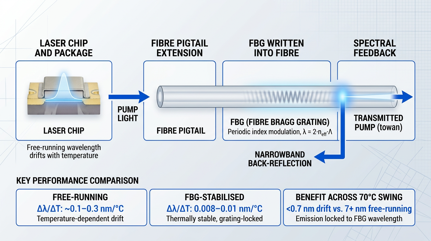
The result is that the laser's emission wavelength is pinned to the FBG reflection wavelength — a property of the grating geometry and fibre refractive index — rather than to the chip's thermally drifting gain peak.
The quantified benefit is significant. FBG-stabilised 980 nm pump modules exhibit a wavelength temperature sensitivity of 0.008–0.01 nm/°C, a figure confirmed across multiple Lumentum and Coherent datasheet specifications. For context, free-running 980 nm InGaAs pump diodes drift at 0.1 nm/°C or more depending on device design, with general InGaAs laser diodes reaching approximately 0.3 nm/°C according to RP Photonics.
| Parameter | Free-Running Diode | FBG-Stabilised Module |
|---|---|---|
| Wavelength temp. sensitivity (Δλ/ΔT) | ~0.1–0.3 nm/°C | 0.008–0.01 nm/°C |
| Wavelength governed by | Chip gain peak (temperature-dependent) | FBG reflection wavelength (thermally stable) |
| Typical spectral width (RMS) | Broadens with temperature and current changes | ≤2.0 nm (narrowband, stable across operating range) |
Quantitative comparison of wavelength temperature sensitivity and spectral behaviour between free-running and FBG-stabilised 980 nm pump lasers, sourced from RP Photonics and Lumentum/Coherent datasheets.
The sensitivity reduction translates directly into amplifier predictability: across a 70°C case temperature swing — a realistic range for an industrial-grade pump module — an FBG-stabilised laser shifts its emission wavelength by less than 0.7 nm, whereas a free-running device could drift by 7 nm or more, moving well outside the erbium absorption peak.
In cascaded DWDM amplifier spans, pump wavelength drift in free-running 980 nm diodes accumulates into measurable gain non-uniformity across channels. FBG stabilisation removes this variable entirely, making pump wavelength a fixed design parameter rather than a thermal uncertainty.
It is worth clarifying what FBG stabilisation does and does not produce spectrally. The stabilised output is not a single longitudinal mode — the laser chip remains a Fabry-Perot structure and continues to support multiple longitudinal modes within the FBG reflection band.
What the FBG provides is a narrowband, spectrally stable envelope. The spectral bandwidth of FBG-stabilised pump modules is typically specified at ≤2.0 nm RMS across Lumentum and Coherent datasheets; some PM-pigtailed modules are specified at ≤0.8 nm RMS, while Thorlabs specifies certain FBG-stabilised pump lasers at 0.5–1.0 nm FWHM — a tighter measurement basis that is not directly comparable to the RMS figures.
For EDFA pumping, the multi-mode nature of the output is irrelevant. The erbium absorption band does not require single-frequency coherence or single longitudinal mode purity — it requires a stable, well-defined pump wavelength that remains within the absorption peak across the full operating range, which FBG stabilisation reliably delivers.
1480 nm Pumping and Wavelength Stability
The 1480 nm case is fundamentally different. The erbium absorption spectrum around 1480 nm is significantly broader and more gradually varying than at 980 nm, meaning the pump wavelength can drift considerably without materially reducing absorption efficiency.
As Lightwaveonline has noted, erbium absorption in the 1480 nm region increases monotonically with pump wavelength but much more slowly than at 980 nm — and the flatter absorption spectrum around 1480 nm generally eliminates the need for wavelength stabilisation.
As a practical consequence, 1480 nm pump modules are typically offered without FBG stabilisation, simplifying module design and reducing cost — a meaningful advantage for high-power booster amplifier applications where multiple 1480 nm pumps may be deployed and where the tightest noise figure control is not the primary objective.
Polarisation adds a further nuance to FBG stabilisation effectiveness in 980 nm modules. The FBG feedback must deliver adequate TE-polarised feedback into the laser cavity to sustain robust wavelength locking — the semiconductor laser chip is polarisation-sensitive, and the polarisation state of the returning reflected light affects how effectively the grating dominates the cavity.
Standard single-mode fibre pigtails exhibit birefringence, which can rotate the polarisation state of the returning reflected light over the pigtail length, potentially reducing stabilisation effectiveness in demanding applications.
Polarisation-maintaining (PM) fibre pigtails address this directly by preserving the polarisation state of the FBG back-reflection along the full pigtail length. The II-VI CM97 series uses a PM fibre pigtail with an integrated FBG specifically to achieve enhanced wavelength and power stability, and Lumentum's 5050 and 5300 series PM-pigtailed modules are similarly specified for applications requiring the most robust wavelength locking.
For applications where stabilisation robustness is paramount — submarine cable amplifiers, ultra-long-haul DWDM systems, or any architecture where the pump operates across a wide temperature range without a TEC — specifying a PM-pigtailed FBG-LD module is the appropriate choice.
Many pump laser modules are also offered with wavelength selection codes that allow engineers to specify the emission wavelength within narrow sub-bands of the broader 980 nm window — for example, 973–975 nm or 975–977 nm, as documented across Lumentum's S27, S32, D2, and H12 series datasheets.
This level of spectral control becomes particularly critical when multiple pump sources are combined in a single amplifier — the subject of the next section — where wavelength matching between pumps directly affects gain flatness and inter-pump interference.
Dual-Pump Configurations: Co-Propagating, Counter-Propagating, and Bidirectional
Every single-pump EDFA faces an inescapable constraint: the direction that minimises noise figure is not the direction that maximises output power, and no amount of pump power can resolve that tension within a single pumping geometry.
The root cause is spatial. Pumping direction determines where along the erbium-doped fibre (EDF) the population inversion peaks — and that spatial distribution governs both how much noise the amplifier adds and how much signal power it can deliver at the output.
Three pumping geometries exist, each producing a distinct excitation profile and a distinct performance trade-off.
- Forward (co-propagating) pumping: Pump travels with the signal. Excitation peaks at the fibre input, where the signal is weakest — the optimal condition for lowest noise figure. Preferred for preamplifier stages.
- Backward (counter-propagating) pumping: Pump travels against the signal. Excitation peaks at the output end, delaying gain saturation and maximising power conversion efficiency. Preferred for booster and power-amplifier stages.
- Bidirectional pumping: Pumps launched from both ends simultaneously. Excitation is distributed along the full fibre length, enabling the highest achievable gain and the best balance of noise figure and output power.
The noise figure advantage of forward pumping follows directly from where inversion is highest: the first few metres of EDF, where the signal enters at its weakest, are the most noise-sensitive region of the amplifier, and maximising inversion there suppresses spontaneous emission at the point where it matters most.
Backward pumping sacrifices that input-end advantage in exchange for stronger pump power at the output, where the signal is already amplified and gain saturation becomes the binding constraint — producing higher output power at the cost of a higher noise figure.
Peer-reviewed analysis confirms these directional relationships: bidirectional configurations yield the highest gain, forward pumping the lowest noise figure, and backward pumping the highest noise figure — with the gap between configurations widening as EDF length increases.
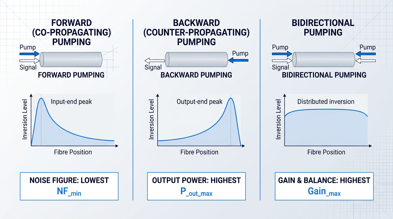
For system designers, the geometry choice is rarely made in isolation: the application context — preamplifier, inline amplifier, or booster — typically dictates which performance axis is primary, and that maps directly to a pumping direction.
The 980 nm Forward + 1480 nm Backward Architecture
When a system demands both low noise figure and high output power simultaneously, neither geometry alone is sufficient — and this is where the most widely deployed dual-pump architecture emerges: a 980 nm co-propagating pump in the first stage combined with a 1480 nm counter-propagating pump in the second.
The logic is a direct synthesis of the wavelength trade-offs established earlier in this guide: 980 nm forward pumping delivers the highest population inversion at the signal input end, producing the lowest possible noise figure; 1480 nm backward pumping then takes over in the output stage, where its superior power conversion efficiency maximises signal output power without the noise penalty that would come from extending 980 nm pumping through a high-gain second stage.
The result is an amplifier that achieves what neither wavelength nor direction can deliver alone — a combination of low noise figure and high output power that makes this architecture the standard configuration for demanding DWDM inline amplifiers and multi-channel systems.
A significant loss element — a gain-flattening filter, dispersion-compensation module, or optical add/drop element — is typically situated between the two stages, with mid-stage access serving both as a functional insertion point and as a natural boundary between the noise-optimised first stage and the power-optimised second.
Where population inversion peaks along the EDF determines both noise figure and output power ceiling. Forward pumping peaks inversion at the input (lowest noise figure); backward pumping peaks it at the output (highest power conversion). No single pump can optimise both ends simultaneously — that is the engineering case for dual-pump configurations.
Dual-Chip Pump Modules
A dual-chip pump module integrates two independently addressable laser diodes into a single hermetically sealed package, enabling multi-stage or bidirectional pumping from one component footprint rather than two discrete modules.
Cooled variants in a 14-pin butterfly package — such as those used in high-power metro and ROADM linecard applications — deliver up to 600 mW kink-free per chip, with a combined optical output exceeding 1.0 W and a maximum combined drive current of 2200 mA, all sharing a single TEC and two independent output fibres.
Uncooled variants in a 10-pin mini-butterfly package address space-constrained designs where TEC power overhead is unacceptable: operating across a –5 °C to +75 °C case temperature range without active cooling, these modules deliver up to 500 mW kink-free per chip with combined optical power up to 1.0 W and total electrical consumption of 1.5–2.0 W per laser diode at maximum output.
Both variants are designed explicitly for arrayed EDFA applications — ADD/DROP ROADM linecards and compact 40/100 Gb/s per-channel amplification — where board space is constrained and deploying two separate butterfly packages is impractical.
The critical operational advantage of dual-chip modules is variable power ratio: because the two diodes are driven independently, the ratio of forward to backward pump power can be adjusted dynamically, allowing real-time optimisation of gain and noise figure across changing channel loads or operating conditions without any physical reconfiguration.
ASE Management in Multi-Pump Designs
Multi-pump configurations — particularly bidirectional designs — introduce a specific amplified spontaneous emission (ASE) challenge: higher total inversion along the EDF increases the ASE power propagating in the forward direction, which accumulates between stages if left unmanaged.
The standard mitigation is an inter-stage isolator placed between gain sections, which blocks backward-propagating ASE from re-entering the first stage while also preventing signal reflections from destabilising the amplifier.
A gain-flattening filter inserted at mid-stage serves a complementary function: it equalises the gain spectrum across the C-band, preventing channels near the 1530 nm erbium gain peak from accumulating disproportionate ASE relative to longer-wavelength channels — a particularly important consideration in DWDM systems where spectral uniformity within 0.5 dB across the full channel plan is a design requirement.
When Dual-Pump Configurations Are Warranted
The added complexity of a dual-pump design is justified when the system specification cannot be met by any single-pump geometry — not merely when performance could be marginally improved.
- Simultaneous NF and output power targets: When specifications demand both a low noise figure (typical of preamplifier stages) and high output power (typical of booster stages) within the same amplifier.
- DWDM systems with wide, flat gain requirements: Multi-channel systems requiring spectrally uniform gain across the full C-band, where a single pump and gain section cannot maintain flatness across all channels.
- Dual-stage designs with mid-stage access: Architectures that insert a dispersion-compensation module, optical add/drop element, or gain-flattening filter between stages — making a two-stage, two-pump layout structurally necessary.
Single-pump configurations remain the right choice for simpler applications — a preamplifier optimised purely for noise figure, or a booster optimised purely for output power — where the added component count and control complexity of dual-pump would add cost without a commensurate performance benefit.
With the configuration architecture understood, the natural next question is how to qualify the pump laser components themselves for long-lifecycle deployment in these demanding systems — which is what the following section addresses.
Telcordia GR-468-CORE and RoHS: Procurement Standards
Once you have resolved wavelength, packaging, thermal management, power, and pump architecture, one question remains before committing to a vendor: can they prove the component will still perform to specification in year twenty?
Telcordia GR-468-CORE is the principal reliability qualification standard for optoelectronic components used in telecommunications infrastructure, and it is the benchmark against which hermetic pump laser modules are formally evaluated.
The standard specifies a structured battery of environmental and mechanical tests designed to simulate the stresses a component will accumulate across decades of continuous field operation.
- Mechanical shock: Validates structural integrity of the hermetic package and internal optical alignment under sudden impact loads.
- Vibration: Confirms that fibre pigtail attachments, TEC connections, and chip bonds remain stable under sustained mechanical vibration.
- Thermal shock: Subjects the module to rapid temperature transitions to expose weaknesses in solder joints and hermetic seals.
- High-temperature ageing: Accelerated stress at elevated temperature to identify early-life failure mechanisms and project long-term degradation.
- Temperature cycling: Repeated thermal excursions across the operating range, stressing package interfaces and optical alignment stability.
- ESD (electrostatic discharge): Tests the laser diode junction's resilience to electrostatic events during handling and integration.
Passing this qualification demonstrates something concrete: the module maintains stable optical output power and stable emission wavelength across all specified test conditions — not just in the controlled environment of a lab bench.
The pass/fail criteria used in GR-468-CORE qualification programmes are consistent with the performance thresholds discussed earlier in this guide: optical output power held within ±10% and wavelength held within ±10 pm across the full test matrix.
The connection to packaging format is direct and non-negotiable: hermetic sealing is a prerequisite for GR-468-CORE qualification, not an optional feature of butterfly or mini-BTF packages.
A module in a non-hermetic enclosure cannot be qualified to this standard for telecommunications infrastructure use — which is why the packaging discussion earlier in this guide carries real engineering weight, not just integration convenience.
The temperature cycling and high-temperature ageing tests within GR-468-CORE are also the formal validation of the thermal management decisions covered previously: a TEC-cooled module qualified at its rated operating temperature has been shown to maintain performance through thousands of thermal cycles, not merely specified to do so.
Vendors who cannot demonstrate GR-468-CORE qualification represent a meaningful procurement risk in systems designed for 25-year operational lifetimes. In professional telecom deployments — submarine, long-haul, or metro — this qualification is the minimum bar, not a premium feature.
When reviewing vendor qualification packages, ask specifically for FIT (failures in time) data — the standard metric for expressing component failure rate in telecom applications.
Published field data for qualified 980 nm pump laser modules shows FIT rates well below 100 at several hundred milliwatts of operating power, with some submarine-deployed devices accumulating field records that translate to approximately 5 FIT.
A compliance statement alone — "qualified to GR-468-CORE" — tells you the module passed the test programme; the FIT figure tells you the quantified failure rate that procurement teams should use to model system reliability over a 25-year lifecycle.
Material compliance sits alongside reliability qualification as a separate but equally non-negotiable procurement requirement.
RoHS Compliance for Pump Laser Modules
The RoHS Directive restricts ten hazardous substances in electrical and electronic equipment placed on EU and GB markets, including lead, cadmium, mercury, hexavalent chromium, and specific phthalates such as DEHP, BBP, DBP, and DIBP.
Pump laser modules fall within scope as electronic components incorporated into finished equipment placed on those markets — the directive's open scope, in force since 2019, covers all EEE unless explicitly excluded, and telecommunications components carry no such exclusion.
Following Brexit, GB RoHS (applying in England, Scotland, and Wales) operates as a parallel regime to the EU RoHS Directive, with substance restrictions and concentration limits that have remained aligned through the period of this guide.
In practice, most professional-grade pump laser modules are available in RoHS-compliant versions; procurement teams should verify compliance status as part of standard vendor qualification rather than assuming it.
With both GR-468-CORE qualification and RoHS compliance established as procurement baselines, the next section brings these requirements together with all the technical selection dimensions covered in this guide into a consolidated decision framework.
Discuss Your EDFA Requirements with Woodrow Scientific
Tell us your wavelength, power, packaging and environmental requirements, and we'll build a custom EDFA to them. View our custom EDFAs or book a call to start the conversation.

Key Selection Criteria for Specifying an EDFA Pump Laser
Engineers who open a pump laser datasheet before defining their system requirements are already working backwards — and the consequences compound at every subsequent step.
Specifying an EDFA pump laser is not eight parallel decisions made in any order; it is a dependency chain where each choice either opens or forecloses the options that follow. Getting the sequence right is as important as getting the individual decisions right.
- Define system requirements first: Establish required gain, target noise figure, output power budget, and operating environment before evaluating any component. These parameters determine which choices are viable.
- Choose pump wavelength: 980 nm for low-noise preamplifiers and metro DWDM; 1480 nm for high-power output stages, remote pumping, or submarine links. This decision is not reversible.
- Derive pump power requirement: Calculate required output power from target gain, EDF length, and signal power levels. Over-specifying adds cost and thermal complexity; under-specifying limits amplifier output under load.
- Select thermal management strategy: Fully TEC-cooled for submarine or high-performance deployments; semicooled for power-constrained DWDM; uncooled with FBG stabilisation for compact metro or access applications.
- Determine packaging format: 14-pin butterfly for fully cooled high-power designs; 10-pin mini-butterfly for semicooled DWDM; mini-DIL or microformat for uncooled compact configurations.
- Evaluate FBG stabilisation need: FBG is mandatory for 980 nm pumps in uncooled or semicooled DWDM EDFAs; typically unnecessary for 1480 nm pumps given the broader erbium absorption band at that wavelength.
- Assess single vs dual-pump: If one pump cannot simultaneously meet noise figure and output power targets, evaluate dual-pump architecture — typically 980 nm forward plus 1480 nm backward for combined performance.
- Verify compliance baseline: Confirm Telcordia GR-468-CORE qualification and RoHS compliance. Request FIT metrics from vendors — suppliers who cannot provide qualification data represent a procurement risk.
The cascade logic becomes clear when you trace a concrete path through the chain: choosing 1480 nm at step 2 immediately simplifies steps 4 and 6.
Because the erbium absorption band at 1480 nm is broad enough to tolerate moderate wavelength drift, FBG stabilisation is not required — and without that constraint, a semicooled or even uncooled thermal strategy becomes viable, which in turn points directly toward a compact packaging format rather than a 14-pin butterfly.
Conversely, a system requirement for a sub-4 dB noise figure in a metro DWDM preamplifier commits the engineer to 980 nm at step 2, which makes FBG stabilisation mandatory at step 6, which then constrains the thermal management strategy at step 4 — three downstream decisions locked in by one upstream commitment.
Pump laser selection done well flows from system requirements to component specification — never the other way around. Engineers who start with a datasheet and work upward to system fit will consistently over-specify some parameters and under-specify others.
The pump laser is, of course, one component within a broader amplifier architecture — and the decisions made here interact with EDF selection, isolator placement, gain flattening filter design, and control electronics in ways that extend well beyond the pump source itself.
Conclusion
Pump Laser Selection as Amplifier Engineering
Every dimension covered here — wavelength, packaging, thermal strategy, power, stability, pump geometry, compliance — pulls on the others, and EDFA pump laser selection only works when those constraints are resolved together, not in sequence.
That is the principle this guide has been building toward: the pump laser is not a component to specify in isolation, but a starting point for the amplifier design as a whole — and that is where the real engineering begins.
Frequently asked questions about EDFA pump lasers
Practical answers covering pump laser selection, FBG stabilisation, thermal management, pumping geometry, and EDFA fundamentals.
Cooled pump lasers use a thermoelectric cooler (TEC) to hold the laser chip at a fixed low temperature — typically 25°C — delivering maximum wavelength and output power stability. Semicooled modules run the TEC at an elevated setpoint (commonly 45°C), significantly reducing TEC power consumption while retaining FBG wavelength stability: a practical middle ground for DWDM EDFAs with constrained power budgets. Uncooled designs eliminate the TEC entirely, relying on FBG stabilisation to manage wavelength drift across the operating temperature range, with the smallest footprint and lowest power consumption of the three. The right choice follows from operating environment and performance requirements. Fully cooled configurations suit submarine and long-haul deployments where maximum performance predictability is non-negotiable. Semicooled suits DWDM applications where power budgets are constrained but wavelength precision remains important. Uncooled is well matched to metro, access, and space-constrained applications where component size and power draw take priority.
Yes — combining both wavelengths is the most common multi-pump architecture in practice. The canonical configuration uses a 980 nm pump co-propagating (forward) in the first stage for a low noise figure, and a 1480 nm pump counter-propagating (backward) in the second stage for high output power. This arrangement exploits the noise advantage of 980 nm pumping — near-complete population inversion near the signal input end — alongside the superior power conversion efficiency of 1480 nm, whose smaller quantum defect makes it better suited to high-power output stages. Dual-chip pump modules housed in a single butterfly or mini-butterfly package can implement this architecture within a compact footprint, making it practical even in space-constrained line-card designs.
A fibre Bragg grating (FBG) provides narrow-band optical feedback that locks the laser emission wavelength to a precise spectral window, preventing drift with changes in temperature and drive current. This is essential for 980 nm pumps in DWDM EDFAs, where even small wavelength shifts alter erbium absorption efficiency and degrade amplifier gain and noise figure. The mechanism works as follows: a slightly reflective FBG written into the module pigtail — typically around one metre from the package — reflects a small fraction of pump light (generally less than five percent) back into the laser cavity, forcing emission to track the FBG reflection wavelength rather than the free-running gain peak. A free-running Fabry-Pérot diode exhibits a temperature coefficient of approximately 0.3–0.4 nm/°C; FBG stabilisation reduces this to roughly an order of magnitude less, maintaining a narrow, stable emission spectrum across the full operating temperature range. Because the erbium absorption band at 1480 nm is considerably broader than at 980 nm, 1480 nm pumps are generally less sensitive to wavelength drift and FBG stabilisation is often optional rather than mandatory at that wavelength.
Forward (co-propagating) pumping maximises excitation density near the signal input end of the erbium-doped fibre — where the signal is at its weakest and most susceptible to noise contribution. High population inversion at this point minimises reabsorption and spontaneous emission at the most noise-sensitive location in the amplifier, producing the lowest achievable noise figure. Backward (counter-propagating) pumping concentrates excitation near the output end instead. This raises output power and power conversion efficiency — the stronger pump power at the output delays the onset of gain saturation — but results in a higher noise figure because the signal traverses a less-inverted section of fibre near the input. This is why forward pumping is the preferred geometry for preamplifier stages, and backward pumping for booster stages where output power matters more than noise figure.
Telcordia GR-468-CORE qualification means the pump laser module has passed a defined set of mechanical, environmental, and endurance tests — including mechanical shock, vibration, thermal shock, temperature cycling, high-temperature ageing, high-temperature storage, low-temperature storage, and ESD — and has demonstrated stable optical output power and wavelength within specified limits across all conditions. Passing these tests provides procurement confidence that the component will perform reliably across a telecommunications infrastructure lifecycle. In professional telecom deployments, GR-468-CORE compliance is effectively a baseline procurement requirement. Vendors who cannot demonstrate qualification represent a meaningful risk in systems expected to operate for 20–25 years. Procurement teams should request qualification test data and FIT (failures in time) rate metrics as part of standard vendor qualification — for individual laser components, Telcordia standards specify FIT-rate targets that qualified vendors should be able to document.
An EDFA amplifies optical signals in the C-band, approximately 1530–1565 nm, which is the primary gain window of erbium-doped fibre. With appropriate pumping schemes and fibre design, amplification can also be extended into the L-band, approximately 1565–1625 nm, to expand capacity in dense WDM systems. It is worth noting that these signal wavelengths are distinct from the pump wavelengths — 980 nm or 1480 nm — which are used to excite the erbium ions and are not themselves amplified. This is a common point of confusion: the pump light drives the gain process, but the wavelengths being amplified are the C-band or L-band signals passing through the doped fibre.
An EDFA works by using a pump laser — operating at 980 nm or 1480 nm — to excite erbium ions (Er³⁺) in a length of erbium-doped optical fibre into a higher-energy metastable state. When signal photons at 1530–1565 nm pass through the doped fibre, they stimulate the excited erbium ions to emit additional photons at the same wavelength and phase, producing optical gain without converting the signal to electrical form. Because amplification is entirely optical, an EDFA can simultaneously amplify many WDM channels across the C-band in a single pass — each channel triggers stimulated emission independently. This property made EDFAs the enabling technology for long-haul DWDM networks, replacing electronic regenerators with a single device capable of amplifying dozens of wavelength channels at once.