

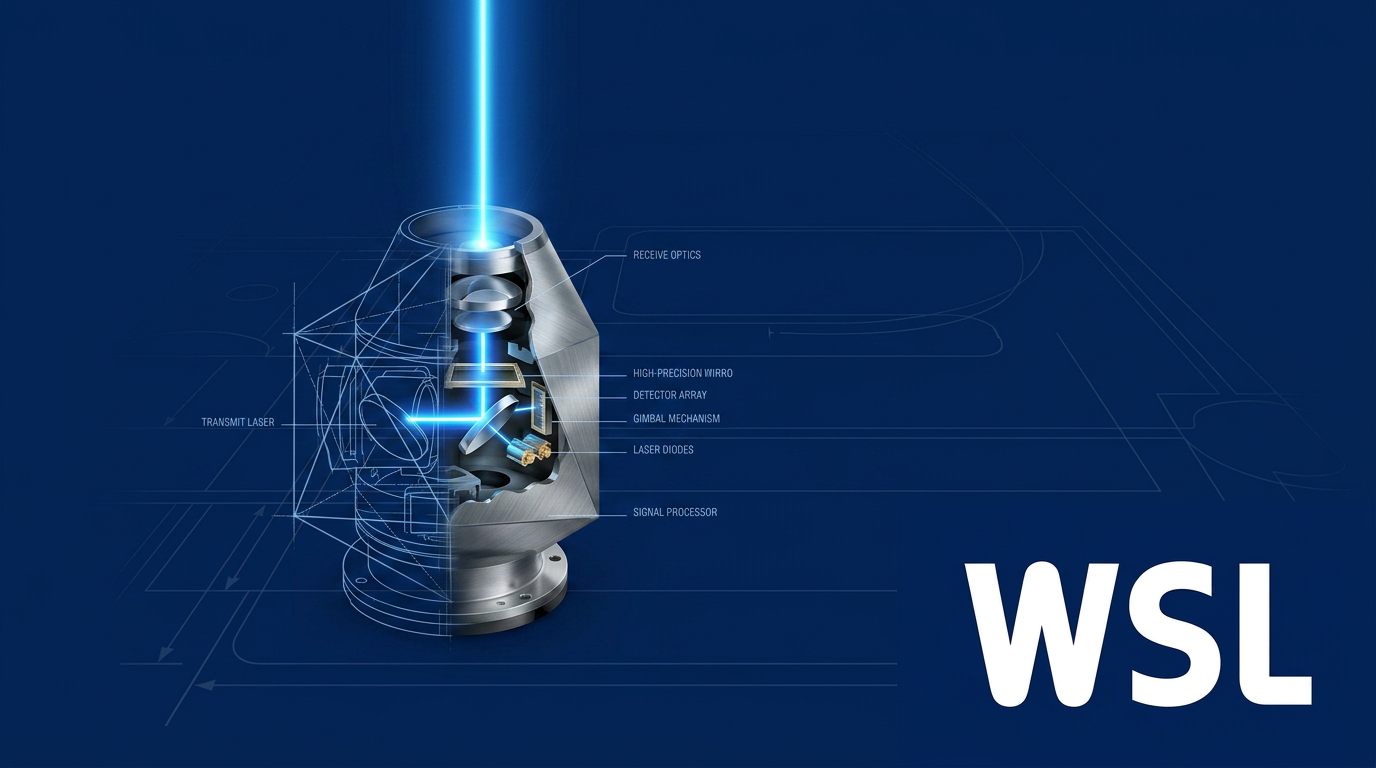
Introduction
Satellite operators are generating more data than radio frequency links can realistically carry back to the ground, and the gap is widening as constellations grow and payloads become more capable.
The space sector has converged on lasercom as its answer — and the shift is well underway, not on the horizon.
What follows covers the full picture: how the technology works, where it struggles, the engineering disciplines that make it viable, the programmes driving its adoption, and the standards beginning to govern it.
It is written for engineers, programme managers, researchers, and procurement professionals who need a substantive reference rather than a surface introduction.
TL;DR
Lasercom has crossed from demonstration into operational deployment — but the hard problems are not solved. Ground network scalability, standards convergence across government and commercial programmes, and fitting capable optical terminals onto small platforms remain genuinely open engineering challenges, and how the industry resolves them will determine how quickly lasercom delivers on its potential.
This article covers:

How lasercom works and its link architecture
Lasercom vs. RF: advantages and trade-offs
Atmospheric challenges and mitigation strategies
Pointing, acquisition, and tracking systems
Small satellite and CubeSat lasercom deployments
Programme landscape: NASA, SDA, ESA, and commercial
What is lasercom?
The word lasercom appears in NASA technology roadmaps, Space Development Agency procurement specifications, and commercial constellation architectures — yet the underlying physics that makes it distinct from every prior wireless communications technology is rarely laid out with precision. That gap matters, because the engineering choices that define a lasercom system (wavelength, modulation format, link segment, terminal aperture) all trace back to a small set of physical principles. Understanding those principles is what makes the rest of the field legible.
At its core, lasercom is the use of optical-frequency electromagnetic radiation — typically in the near-infrared — to transmit data wirelessly between terminals in free space. The terms "laser communications", "free-space optical (FSO) communications", and "optical communications" are used interchangeably across the space sector and the broader wireless community; this guide uses lasercom throughout when referring to space applications.
The physics of optical transmission
The defining physical difference between lasercom and radio frequency (RF) communications is the carrier frequency. Optical frequencies used in lasercom sit in the range of roughly 200–300 THz, compared to approximately 32 GHz for Ka-band RF — a difference of nearly four orders of magnitude.
That higher carrier frequency has a direct consequence for beam divergence — the angular spread of the transmitted beam. Divergence scales with the ratio of wavelength to aperture diameter: a shorter wavelength produces a narrower beam for a given aperture size. Because optical wavelengths are orders of magnitude shorter than RF wavelengths, a lasercom terminal can concentrate its transmitted energy into a far tighter cone than an RF system of equivalent aperture.
Higher carrier frequency also governs available bandwidth. The usable bandwidth of any communications system is bounded by a fraction of its carrier frequency, so optical carriers offer a fundamentally larger pool of available bandwidth than RF carriers — a physical ceiling that RF systems, regardless of modulation sophistication, cannot exceed.
Operating wavelengths: 1064 nm and 1550 nm
Practical lasercom systems operate in two dominant near-infrared wavelength bands: 1064 nm and 1550 nm. Both sit within atmospheric transmission windows where absorption by water vapour and other constituents is relatively low, and both benefit from mature laser source and detector technology developed over decades of terrestrial and defence applications.
The two bands differ in a practically important way: 1550 nm carries a higher eye-damage threshold than 1064 nm. At 1550 nm, the cornea and lens absorb the radiation before it reaches the retina, which raises the maximum permissible exposure compared to 1064 nm light, where the eye's optics focus the beam onto the retina. For ground station operations and co-located facilities, this distinction has real consequences for site safety planning. It does not, however, mean 1550 nm is safe without precautions — it remains a Class 4 laser wavelength, and full laser-safety procedures and appropriate eyewear are required.
On the technology side, 1550 nm benefits from the mature ecosystem of erbium-doped fibre amplifier (EDFA) technology built for terrestrial telecommunications networks, enabling high-gain optical amplification with well-understood noise characteristics. The 1064 nm band offers complementary advantages: silicon avalanche photodiodes operate efficiently at this wavelength, and 1064 nm is the choice for a number of deep-space and optical inter-satellite link (OISL) applications where detector efficiency and laser source performance at that wavelength are priorities.
Modulation and detection
Lasercom systems do not use a single universal approach to encoding data onto the optical carrier. Instead, the choice of modulation format and detection architecture reflects a fundamental trade-off axis: photon efficiency versus data rate and spectral efficiency.
Intensity modulation with direct detection (IM/DD) is the simplest architecture. Data is encoded in the intensity of the optical beam; the receiver detects optical power directly, typically using an avalanche photodiode (APD). At the high-sensitivity extreme of direct detection sit photon-counting receivers — using single-photon APDs or superconducting nanowire single-photon detectors — which can register individual photons and are suited to power-limited links where extracting the maximum information from every received photon is the priority.
Pulse position modulation (PPM) is the established standard for deep-space optical links. Rather than encoding data in amplitude or phase, PPM encodes information in the time position of a pulse within a defined frame. This approach offers a high peak-to-average power ratio and is highly photon-efficient, making it well matched to photon-counting receivers. When the received signal power is extremely low — as it is on links spanning tens or hundreds of millions of kilometres — PPM's ability to extract information from very few photons per bit makes it the preferred choice.
Coherent detection takes a different approach: data is encoded in the phase (or combined amplitude and phase) of the optical carrier, and the receiver recovers that phase information by mixing the incoming signal with a stable local oscillator laser. The frequency relationship between the local oscillator and the signal defines whether the architecture is homodyne or heterodyne. Specific modulation formats within this family — including BPSK, QPSK, and DPSK — offer higher spectral efficiency and better receiver sensitivity at high data rates than direct detection, at the cost of significantly greater terminal complexity.
The practical consequence of this spectrum is that link type drives modulation choice. Deep-space links, where received power is vanishingly small, favour PPM with photon-counting detection. High-rate near-Earth links and OISL applications, where power is less constrained and throughput is the objective, tend to favour coherent detection. Ground downlinks often sit somewhere between, with the specific choice shaped by terminal SWaP constraints and link margin.
The three link segments
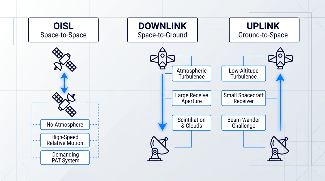
A complete lasercom architecture is typically described in terms of three distinct link segments, each presenting a different channel environment and a different set of engineering challenges.
- Space-to-space (OISL): Links between satellites in orbit. No atmosphere, but terminals move rapidly relative to each other, placing stringent demands on pointing, acquisition, and tracking.
- Space-to-ground (downlink): From spacecraft to ground station. The signal traverses the full atmosphere near the receiver; turbulence, scintillation, and cloud blockage are the primary channel impairments.
- Ground-to-space (uplink): From ground station to spacecraft. Atmospheric turbulence near the transmitter causes beam wander at the spacecraft receiver, with no large aperture available to average it out.
The uplink and downlink atmospheric impairment profiles are not symmetric. On the downlink, a large ground-based receive aperture can spatially average turbulence-induced intensity fluctuations. On the uplink, low-altitude turbulence near the transmitting aperture imprints beam wander that the small spacecraft receiver cannot mitigate in the same way — making the uplink, in general, the harder atmospheric problem of the two. OISL segments avoid atmospheric impairments entirely, but the absence of a fixed, stable channel places demanding requirements on the pointing, acquisition, and tracking (PAT) system that must continuously align two fast-moving terminals.
Several terms introduced across this section will recur throughout the guide without re-definition: the link budget is the end-to-end accounting of transmitted power, path losses, and received signal level that determines whether a link closes; aperture is the collecting area of the optical telescope or antenna at each terminal; beam divergence is the angular spread of the transmitted beam; PAT is the subsystem responsible for acquiring and holding alignment between terminals; SWaP (size, weight, and power) describes the physical resource envelope that constrains terminal design, particularly on smaller spacecraft; and modulation format denotes the specific scheme used to encode data onto the optical carrier.
With the physical principles and architectural vocabulary in place, the natural next question is what these properties mean in practice — specifically, how lasercom compares against the radio frequency systems it is increasingly being deployed alongside, and in some cases replacing.
Lasercom vs. RF: the case for optical
Satellite operators are running out of RF headroom. As Earth observation payloads grow more capable and LEO constellations proliferate, the data volumes they generate are outpacing what Ka-band links can realistically return to the ground — and the spectrum itself is becoming a contested resource. Lasercom addresses this pressure at the physics level, not through incremental engineering refinement of RF.
The root advantage is carrier frequency. Optical carriers sit at roughly 200–300 THz, compared with Ka-band's 26–40 GHz — a ratio of approximately 6,000:1. Because the bandwidth available to a communications link scales with carrier frequency, an optical channel can support data rates that are structurally inaccessible to RF, not merely difficult to achieve.
Programme-demonstrated figures make this concrete. NASA's LLCD achieved a 622 Mbps downlink from lunar orbit in 2013 using a 0.5 W transmitter — while massing roughly half of the comparable RF terminal on the Lunar Reconnaissance Orbiter (30.7 kg versus 61 kg) and consuming 25% less power. NASA's LCRD relay operates at 1.244 Gbps bidirectionally from GEO. And NASA's TBIRD payload, a 3U package on a 6U CubeSat, demonstrated 200 Gbps direct-to-Earth from LEO — the highest downlink rate ever achieved by any space platform — transferring more than 4.8 TB in a single five-minute pass.
The second physical root of the advantage is beam divergence. Because divergence scales as θ ≈ λ/D, and optical wavelengths are roughly four orders of magnitude shorter than RF wavelengths, a given aperture produces a far narrower beam in the optical domain. At lunar distance, a 10 cm optical aperture at 1550 nm illuminates a spot of roughly 6 km; a Ka-band antenna of 75 cm illuminates a spot of roughly 6,400 km at the same range — more than a thousand times the diameter.
The link efficiency consequence is direct: energy delivered per unit area at the receiver is vastly higher for an optical beam, meaning far more received signal power per watt of transmit power — which translates into a fundamentally more efficient link budget. These advantages compound across multiple dimensions, as the table below shows.
| Dimension | RF (Ka-band) | Lasercom (optical) |
|---|---|---|
| Carrier frequency | 26–40 GHz | ~193–300 THz (~6,000× higher) |
| Demonstrated data rate (space) | ~500 kbps–110 kbps at 2.6 AU (Mars Odyssey); up to a few Gbps near-Earth with large ground arrays | 200 Gbps (TBIRD, 6U CubeSat LEO); 1.244 Gbps (LCRD, GEO relay) |
| Beam spot size at lunar distance | ~6,400 km (75 cm Ka-band antenna) | ~6 km (10 cm optical aperture at 1550 nm) |
| Spectrum licensing | FCC/ITU coordination required; Ka/Ku bands increasingly congested | Unregulated; no ITU or FCC frequency assignment required |
| Intercept resistance | Wide footprint (hundreds–thousands of km); interceptable with directional antenna | Narrow beam; signal confined to small spot; harder to intercept without being in beam path |
| Flight terminal mass (deep space) | Baseline (100%) | ~55–65% of equivalent RF terminal mass (JPL TMO study) |
Lasercom vs. RF comparison across key link performance dimensions, using programme-demonstrated and physics-derived figures
The table's most striking pattern is the simultaneity of the advantages: lasercom does not trade one benefit for another. The same narrow beam that concentrates energy on the receiver also shrinks the required terminal aperture, reduces transmit power, and confines the signal footprint. The JPL deep-space study found that optical flight terminals mass approximately 55–65% of the equivalent RF terminal — a SWaP reduction that compounds at the system level into lower launch costs, smaller host spacecraft interfaces, and greater design margin across the mission lifetime.
The ~6,000:1 carrier frequency ratio between optical and Ka-band is not just a bandwidth multiplier — it simultaneously produces the narrower beam, the smaller terminal aperture, the SWaP reduction, and the intercept resistance. These advantages share one root cause, which is why they cannot be replicated by incremental RF improvements.
The spectrum licensing advantage is operationally significant and tends to be underweighted in technical comparisons. RF frequencies require FCC assignment for commercial operators and NTIA coordination for government users, with ITU coordination for international operations — a process that can take years and is growing more contested as proliferated LEO constellations compete for the same Ka and Ku allocations. Optical frequencies are currently unregulated: no ITU coordination is required, no FCC frequency assignment is needed, and a new lasercom terminal can be deployed without regulatory clearance or interference risk from other optical users.
The narrow beam also confers inherent low probability of intercept and resistance to jamming. A ~6 km optical spot at lunar distance does not illuminate a geographic footprint that a ground-based adversary can casually monitor; intercepting the signal requires being within the beam path. NASA's own State of the Art documentation confirms that lasercom links are difficult to jam because of the narrow beamwidth, and that optical frequencies encounter very little interference for the same reason — properties that make lasercom particularly attractive for defence and government applications.
One genuine structural limitation deserves direct acknowledgement: lasercom is inherently a point-to-point technology. The narrow beam that delivers every advantage above cannot simultaneously illuminate many geographically dispersed users, as an RF broadcast beam can. This is a design constraint that defines where lasercom is the right choice — high-throughput dedicated links (satellite-to-ground data downlinks, inter-satellite relay, deep-space high-rate return) — not a deficiency that undermines the case for it.
The physics case is compelling — but realising these advantages in an operational link requires solving real engineering challenges. The sections that follow address what stands between the physics and the working system.
Atmospheric challenges and mitigation strategies
Every design decision in a lasercom ground segment — how many stations to build, where to place them, how large to make the receive aperture, whether to deploy adaptive optics — is ultimately a response to the same underlying constraint: the atmosphere. Unlike the gradual, partial signal degradation that rain fade imposes on RF links, the optical channel presents impairments that can be complete, sudden, and physically irrecoverable through link margin alone.
Cloud blockage and site diversity
Clouds impose complete optical attenuation — not a fade, but a blockage. As the JPL DESCANSO monograph notes, cloud attenuation can reach tens of decibels in cases such as cumulonimbus, making effective communication through clouds infeasible. This creates a hard binary requirement: cloud-free line of sight (CFLOS) must exist for the link to operate at all. No practical amount of link margin or forward error correction coding gain can recover a signal through complete blockage.
Because CFLOS is a binary condition, the engineering response must operate at the network level rather than the link level. Site diversity — deploying geographically separated ground stations whose cloud cover is statistically uncorrelated — is the primary architectural tool. NASA's Laser Communications Relay Demonstration (LCRD) provides a concrete operational data point: its two optical ground stations, OGS-1 at Table Mountain, California and OGS-2 at Haleakalā, Hawaii, have demonstrated an overall session success rate of approximately 59%, rising to approximately 79% when sessions disrupted solely by weather are counted as operationally successful.
The LCRD data also illustrates the challenge that remains even with two well-separated sites: OGS-1 achieved weather availability of approximately 57.8% and OGS-2 approximately 40.5% over the initial experiment period, and the predicted simultaneous CFLOS for the Table Mountain–Haleakalā pair is approximately 48.2%. Extending to networks of three or more stations — with sites selected to maximise geographic separation and minimise cloud-cover correlation — is the established path to reaching the link availabilities that operational services require.
No coding scheme or power margin can recover a signal through cloud blockage. The only viable response is a ground network designed so that at least one station always has CFLOS — which means site selection and geographic distribution are as critical to lasercom system design as the optical terminal itself.
Turbulence, scintillation, and beam wander
When the sky is clear, the atmosphere remains a dynamic, optically imperfect medium. Thermal gradients, wind shear, and convective mixing create turbulent eddies that produce random spatial and temporal variations in the refractive index of air. These variations perturb any laser beam propagating through them, producing three physically distinct effects: scintillation (irradiance fluctuations at the receiver), beam spreading (widening of the beam beyond its diffraction-limited size), and beam wander (drift of the beam centroid). These effects are often conflated in superficial treatments, but they have different physical origins and drive different mitigation approaches.
Scintillation arises when turbulent cells of varying refractive index act as weak lenses, creating constructive and destructive interference across the beam's cross-section. The receiver sees rapid intensity fluctuations — fades and surges — whose statistics are characterised by the scintillation index (σ²_I), the normalised variance of received irradiance. The strength of scintillation scales with the atmospheric structure parameter C²_n, the propagation path length, and the optical wavenumber, as described by Rytov theory for weak fluctuation conditions.
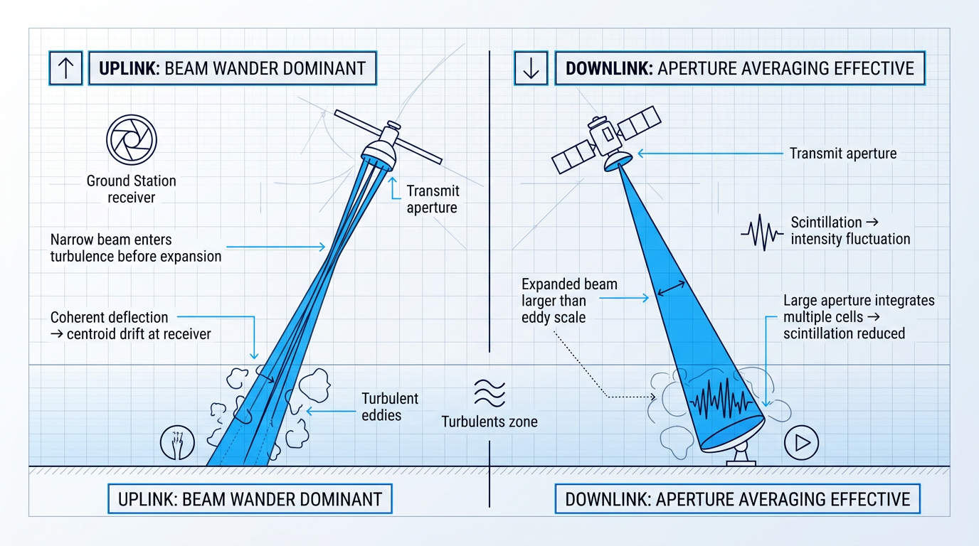
Beam wander on the uplink is a qualitatively different and particularly severe impairment. Low-altitude turbulence near the ground transmitter intercepts the beam while it is still narrow — before it has expanded significantly over the propagation path. Because the beam diameter is smaller than the dominant turbulent eddy size at these altitudes, the entire beam is deflected coherently, causing the beam centroid to wander at the spacecraft receiver by distances that can reach several hundred metres. On the downlink, the situation is reversed: the beam has already expanded to a size larger than the outer scale of turbulence by the time it enters the lower atmosphere, so the ground receiver sees a large, spatially averaged illuminated area rather than a wandering spot.
The mitigation toolkit
Aperture averaging is the primary mitigation for downlink scintillation. A larger receive aperture integrates the irradiance over multiple turbulence cells simultaneously, averaging out the intensity fluctuations — the scintillation index decreases as aperture diameter increases. Large ground apertures are practical and effective, making downlink scintillation a largely tractable problem for well-resourced ground stations. Aperture averaging does not, however, help the uplink: the transmitting aperture is at the ground, and the beam remains narrow as it enters the turbulent boundary layer, so the spacecraft receiver still sees a wandering, fluctuating spot regardless of how large the ground transmitter aperture is.
The transmit-side equivalent is multi-beam aperture diversity. When multiple transmit apertures are separated by more than the atmospheric coherence length r₀ (the Fried parameter — the characteristic scale over which the atmosphere remains spatially coherent), the beams accumulate statistically independent phase and amplitude errors and arrive at the spacecraft receiver with uncorrelated intensity fluctuations. Because they add incoherently at the receiver, the effective scintillation index is reduced relative to a single-aperture uplink. Apertures must be separated by more than r₀ for this diversity benefit to materialise; two- and four-emitter configurations are used in operational uplink ground station designs.
Adaptive optics (AO) addresses the wavefront distortion that turbulence imposes on the beam. A wavefront sensor measures atmosphere-induced phase errors — typically using a reference beacon or downlink signal from the spacecraft — and a deformable mirror applies the conjugate correction in real time, enabling near-diffraction-limited propagation. On the downlink, AO enables efficient coupling of the received beam into single-mode fibre at the ground modem. On the uplink, AO pre-distorts the transmitted wavefront to partially compensate turbulence along the path and reduce beam wander at the spacecraft; laboratory and field experiments have demonstrated that pre-distortion AO can reduce uplink scintillation by an order of magnitude and ease link budget requirements considerably.
A practical complication for uplink AO is the point-ahead angle: because the spacecraft moves during the finite light travel time, the uplink and downlink beams traverse slightly different atmospheric volumes. This anisoplanatism limits how accurately a correction derived from the downlink beacon can compensate the uplink path, and its severity depends on satellite velocity and turbulence profile. Sodium laser guide star approaches — as developed in the ESA ALASCA project — are being pursued specifically to provide a wavefront reference closer to the actual uplink path, though the geometry of the point-ahead angle remains a fundamental constraint on achievable correction fidelity.
Forward error correction (FEC) combined with interleaving provides a complementary layer of resilience through moderate turbulence-induced fades. Turbulence fades are temporally correlated — a fade event persists for a characteristic duration determined by the atmospheric coherence time — which means they produce burst errors rather than the random, independent errors that FEC codes are designed to correct. Interleaving spreads the bits of each codeword across time so that a burst error affects only a fraction of any given codeword, allowing the FEC to recover the data. Research on lasercom interleaver design confirms that the temporal diversity parameter L — the number of statistically independent fade events experienced by a codeword — is the key design variable: as L decreases below a critical threshold, power penalties grow rapidly, making interleaver depth a system-level design choice tied directly to the channel coherence time.
The fundamental asymmetry between uplink and downlink runs through all of these mitigations. Downlink scintillation is largely addressed by aperture averaging at the ground receiver — a well-understood and implementable solution. Uplink beam wander and scintillation are the harder, less fully solved problems: they require multi-beam transmit diversity, fast-tracking transmitters, and adaptive optics pre-compensation, all of which must contend with the point-ahead angle and the fact that the narrow transmitted beam encounters the most turbulent part of the atmosphere before it has had any chance to expand.
Characterising the atmospheric channel — its impairments, their physical mechanisms, and the engineering toolkit available to mitigate them — sets the stage for the next major challenge in lasercom system design. The atmosphere moves the beam; keeping it locked on a target thousands of kilometres away, despite that movement and despite the spacecraft's own orbital motion, is the domain of pointing, acquisition, and tracking.
Pointing, acquisition, and tracking
Consider what a lasercom terminal must actually do: keep a beam that diverges on the order of microradians centred on a receiver aperture measured in centimetres, across tens of thousands of kilometres, from a platform subject to structural vibration, thermal drift, and attitude control deadband that can each be orders of magnitude larger than the permitted pointing error.
That gap between the disturbance environment and the required accuracy is the central engineering challenge of pointing, acquisition, and tracking (PAT). As established in the Background, beam divergence at optical wavelengths scales with wavelength divided by aperture — producing transmit beamwidths on the order of a few microradians for typical lasercom terminals. The required pointing accuracy is a small fraction of that beamwidth: for deep-space links, JPL analysis confirms that the required pointing accuracy is a small fraction of a microradian, with the flight terminal needing to achieve this in the presence of spacecraft platform jitter and attitude-control deadband that can be several orders of magnitude larger.
The PAT sequence: acquisition, pull-in, and tracking
Before any data can flow, every lasercom terminal must execute a structured three-phase sequence to bring the link from cold geometry to closed-loop alignment.
- Acquisition: A wide-field search locates the counterpart terminal. Prior orbital knowledge constrains the search volume, but a systematic scan or stare strategy is still required to handle residual uncertainty.
- Pull-in (coarse-to-fine transition): The terminal transitions from the wide-field acquisition detector to the fine-tracking sensor, progressively narrowing angular uncertainty until the fine tracker can lock.
- Closed-loop tracking: With the fine tracker locked, the control loop maintains beam alignment continuously, compensating for spacecraft motion, vibration, and thermal drift throughout the pass.
For space-to-ground links, a ground-based beacon uplink is the standard architecture enabling this sequence: the ground station transmits a beacon laser upward, the spacecraft terminal acquires and tracks it, and then points its own downlink beam back at the beacon source.
This approach neatly transfers the pointing burden: the spacecraft only needs to track the beacon it is receiving, rather than compute an absolute pointing solution from scratch. It is worth noting that the beacon uplink traverses the same atmospheric path — and is subject to the same beam wander — that the atmospheric section identified as the harder direction; PAT systems must handle atmosphere-induced beam wander on the uplink in addition to spacecraft motion.
The fine-tracking detector that locks onto the beacon is typically one of two architectures: a quad-cell detector, which derives a pointing error signal directly from the intensity imbalance across four quadrants and offers high bandwidth with low computational overhead; or a focal-plane array, which captures a full image of the beacon spot and can handle more complex scenarios such as multiple sources or non-uniform backgrounds, at the cost of greater processing demand.
Hardware architecture: gimbals, FSMs, and nested control
Achieving sub-arcsecond pointing across a wide field of regard requires two complementary mechanisms operating in a nested control loop: a coarse stage with wide angular range and a fine stage with high bandwidth.
- Gimbals (coarse pointing): Provide pointing across a wide field of regard — potentially hemispherical — but have limited control bandwidth and cannot reject high-frequency vibration disturbances.
- Fast steering mirrors (fine pointing): Operate at high bandwidth within the terminal, correcting residual gimbal error and platform vibration at rates of hundreds to thousands of Hz.
The MAScOT terminal, developed for NASA's ILLUMA-T and O2O missions, demonstrates what this nested architecture can deliver: cascaded and nested control loops achieve sub-arcsecond (less than 4 µrad) beam pointing across a ±120° elevation and ±175° azimuth field of regard — effectively hemispherical coverage at precision pointing.
A key design lever in MAScOT is optical magnification: a 43.25× magnification factor in the beam path de-magnifies angular pointing changes from the steering mirrors, so a 35-arcsecond correction in the internal beam space translates to a 0.8-arcsecond change at the output aperture — enabling high precision without requiring exceedingly complex beam steering mechanisms.
Body-pointing: an alternative for small platforms
A two-axis gimbal adds mass and mechanical complexity that may be incompatible with small satellite SWaP budgets. The alternative is body-pointing: rather than steering the terminal relative to the spacecraft bus, the spacecraft itself slews to point the payload, with the lasercom terminal providing real-time pointing feedback to the spacecraft attitude control system (ADCS).
NASA's TBIRD mission — a 3U lasercom payload on a 6U CubeSat — is the canonical demonstration of this architecture. On-orbit results show closed-loop body-pointing performance of 20–35 µrad RMS per axis, with the payload tracking the ground station beacon uplink and feeding pointing corrections back to the spacecraft ADCS throughout each pass.
The outcome validates the approach decisively: TBIRD achieved 200 Gbps downlink rates and demonstrated error-free transfer of more than 1 Terabyte in a single 5-minute pass, with pointing loss kept to a fraction of a dB — all without any dedicated pointing mechanism on the payload itself.
The trade-off is that body-pointing shifts the precision burden onto the spacecraft bus: the ADCS must respond accurately to payload feedback commands, and the slew rate available for link maintenance is constrained by bus dynamics rather than by a dedicated fast-steering mechanism on the payload.
Beaconless pointing for deep space
At interplanetary distances, a ground-based beacon uplink becomes impractical: round-trip light time precludes closed-loop feedback, and the beacon power required to be detectable at such ranges is prohibitive. The solution is beaconless pointing, which replaces the active beacon with passive celestial references.
JPL analysis, published in TMO Progress Report 42-161, shows that a star tracker combined with inertial sensors can achieve pointing knowledge of approximately 150 nrad (single axis, 1σ) with an 8 cm aperture telescope, assuming SIRTF-class gyros and 5-Hz star tracker updates — well below the typical deep-space optical communications requirement of 200–300 nrad, leaving meaningful margin for link availability.
The DESCANSO Chapter 5 analysis corroborates this figure and notes that link availability can be maintained above 98% with a single star tracker under these assumptions, making beaconless operation a viable and mission-proven architecture for deep-space lasercom.
PAT maturity: operational benchmarks
Two operational programmes illustrate where PAT technology now stands across different link classes.
| Programme | Link Type | Terminal Separation | Acquisition Time | Operational Status |
|---|---|---|---|---|
| EDRS (ESA) | GEO-to-LEO optical inter-satellite | Up to 45,000 km | ~55 seconds | Operational — 50,000+ links established |
| SDA Tranche 0 | LEO-to-LEO OISL | LEO constellation spacing | Well under 100 s (stretch goal: <10 s) | On-orbit demonstration; link maintained for several hours |
Side-by-side comparison of EDRS and SDA Tranche 0 PAT performance benchmarks across link type, terminal separation, acquisition time, and operational status.
These two benchmarks are complementary rather than competitive. EDRS demonstrates mature, repeatable operational performance across a demanding GEO-LEO geometry: locking a 135 mm aperture target at 45,000 km separation, with one terminal travelling at 8 km/s relative to Earth, in approximately 55 seconds — a feat now replicated across more than 50,000 links.
The SDA Tranche 0 demonstration addresses a different problem: LEO-LEO optical inter-satellite link (OISL) acquisition in a proliferated constellation context, where rapid autonomous acquisition between co-orbiting nodes is the key operational requirement. Achieving acquisition well under the 100-second requirement — and sustaining the link for several hours — confirmed that PAT for LEO mesh networking is operationally viable.
Across GEO-LEO relay (EDRS, 50,000+ links), LEO-LEO OISL (SDA Tranche 0), and deep-space beaconless architectures (JPL analysis, 150 nrad pointing knowledge), PAT has been demonstrated at operational maturity. The remaining engineering challenge is miniaturisation and cost reduction — not feasibility.
Body-pointing, introduced here through the TBIRD example, is one of the key architectural enablers that brings lasercom within reach of small satellite platforms — and the next section examines the full picture of what those platforms demand, from power budgets and mass constraints to COTS component leverage.
Lasercom on small satellites and CubeSats
The engineering case for deploying lasercom on small satellite platforms is compelling: CubeSats are cheap to build and launch, they can be fielded in large constellations, and optical links offer the data-rate headroom that RF simply cannot. The problem is that lasercom as a technology is resource-hungry in precisely the ways that small satellite buses are resource-constrained. High pointing accuracy demands a capable ADCS or dedicated actuators. Meaningful transmit power demands electrical power budget. Sensitive detection hardware demands volume and thermal management. Every one of those requirements collides directly with the SWaP (size, weight, and power) envelope of a CubeSat bus.
Of the three SWaP axes, power is arguably the most binding constraint. A 3U CubeSat typically has less than 10 W of total available power shared across all subsystems: attitude determination and control, command and data handling, housekeeping, and communications. A lasercom terminal must compete within that envelope, and transmit power directly determines link margin — the margin between received signal strength and the minimum detectable threshold. Compress transmit power too far and the link margin collapses, forcing trade-offs against data rate, range, or both.
Miniaturised terminals: demonstrated hardware
Despite these constraints, several terminals have been demonstrated or productised at CubeSat-compatible scale. The table below compares the four most significant examples, drawing on first-party Tesat specifications and NASA mission data.
| Terminal | Form Factor | Mass | Data Rate | Power Consumption | Platform / Status |
|---|---|---|---|---|---|
| Tesat CubeL | 1×1×0.3U (~10×10×3 cm) | ~350 g | 100 Mbps | 8 W | CubeSat DTE; in development/CDR passed |
| Tesat SCOT20 | 1U (10×10×11.35 cm) | 1.7 kg | 100 Mbps | <35 W peak | Small satellite LEO/DTE; delivered to customer |
| NASA TBIRD payload | 3U (on 6U CubeSat host) | <3 kg | 100 / 200 Gbps | ~100 W peak | LEO DTE; launched May 2022, all objectives met |
| NASA OCSD (B/C) | 1.5U (10×10×17 cm) | ~2.18 kg (wet) | 200 Mbps | Not published | LEO DTE; demonstrated on orbit 2017–2018 |
Comparison of demonstrated small-platform lasercom terminals across form factor, mass, data rate, and power consumption, to show the engineering trade space concretely.
The table reveals a stark discontinuity in the design space. The CubeL and SCOT20 achieve 100 Mbps within tight power and mass budgets — genuinely useful for small satellite downlink applications — but they operate roughly three orders of magnitude below TBIRD's 200 Gbps burst rate. TBIRD reaches that performance by accepting a larger platform (a 3U payload on a 6U host bus), a peak power draw of approximately 100 W sustained only during the short pass window, and a ground terminal capable of compensating for the constrained space-segment aperture. The OCSD result sits in an intermediate zone: 200 Mbps from a 1.5U platform is impressive, but the architecture and ground terminal requirements differ substantially from TBIRD's coherent fibre-telecom approach.
What the table cannot capture is the system-level complexity behind each row — particularly the pointing architecture that makes any of these links possible at all.
Pointing architecture trade-offs on small platforms
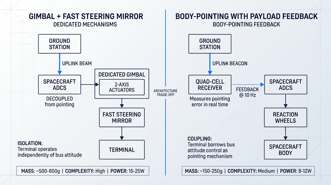
On large satellite platforms, the standard approach to lasercom pointing uses a hierarchy of dedicated mechanisms: a coarse gimbal provides a wide field of regard, and a fast steering mirror handles fine correction at high bandwidth. This isolates pointing from spacecraft attitude dynamics and allows the terminal to operate largely independently of the host bus. On a CubeSat, that approach is often unaffordable: a two-axis gimbal and FSM assembly adds mass, volume, and mechanical complexity that may consume more SWaP budget than the terminal itself.
The alternative, demonstrated by TBIRD, is body-pointing with payload feedback: no dedicated actuators on the terminal at all. Instead, the payload's quad-cell uplink receiver measures the pointing error in real time and feeds two-axis corrections to the spacecraft's ADCS at 10 Hz. The bus then manoeuvres the entire spacecraft using its reaction wheels to maintain beam alignment throughout the pass. The lasercom terminal is effectively borrowing the spacecraft's own attitude control system as its pointing mechanism.
This approach eliminates the mass and volume cost of dedicated mechanisms, but it imposes tight coupling between the terminal and the host bus. The ADCS must be capable of responding to payload feedback at the required bandwidth, and the spacecraft must sustain slew rates up to approximately 1 deg/s to track a ground station during a LEO pass. TBIRD demonstrated 20–35 µrad RMS per-axis pointing accuracy using this architecture — sufficient to keep pointing losses below 0.1 dB for its 380 µrad FWHM downlink beam, a result the Riesing SPIE 2023 paper identifies as the best closed-loop body-pointing performance demonstrated by a nanosatellite at the time.
OCSD took a related but distinct approach. The laser is hard-mounted to the spacecraft body with no beam-steering optics whatsoever, and pointing is achieved entirely by controlling spacecraft attitude using miniature star trackers and reaction wheels. This beaconless architecture — relying on star trackers and inertial sensors rather than a ground-uplink beacon to establish pointing knowledge — made the optical system exceptionally compact, which was essential for a 1.5U platform. OCSD-B and C demonstrated 200 Mbps downlink to a 40 cm ground telescope, with pointing accuracy better than 0.05 degrees, a result that was at the time 20 times more precise than previously demonstrated for a satellite of that size.
Together, TBIRD and OCSD define the current state of the art for small-platform lasercom. TBIRD holds the data-rate record: 200 Gbps burst downlink from a 6U CubeSat, with a peak demonstrated data volume of 4.8 TB transferred error-free in a single five-minute pass. OCSD holds the platform-size record for a demonstrated free-space optical downlink, showing that beaconless lasercom from a 1.5U CubeSat is not merely theoretical.
A central enabler of TBIRD's performance was its deliberate use of COTS (commercial off-the-shelf) fibre telecommunications transceivers operating at 1550 nm — components developed for terrestrial fibre networks, not for space. Leveraging these components, rather than developing radiation-hardened space-qualified equivalents from scratch, compressed both development cost and schedule substantially. The mission explicitly validated the use of terrestrial COTS components in the space-to-ground link environment as one of its primary objectives.
The engineering caveat is important: COTS components are not radiation-hardened to the same standard as space-qualified parts. For TBIRD operating in LEO at 530 km altitude, the radiation environment is comparatively benign, and the mission managed the risk through component screening and acceptance of some performance variation. That trade-off does not transfer automatically to higher-orbit or deep-space applications, where accumulated radiation dose and single-event effects are substantially more severe. TBIRD's success validates the COTS approach for LEO specifically; it is not a blanket endorsement for GEO or interplanetary missions.
Reducing SWaP on the space segment does not reduce total system complexity — it redistributes it. TBIRD's constrained space terminal required JPL's 1 m OCTL telescope with adaptive optics to close the link. Programme designers must account for this asymmetry when sizing the ground network: a smaller satellite terminal is not a cheaper system end-to-end, it is a system with a different cost distribution.
This ground-station asymmetry is a genuine system-level design constraint, not a secondary procurement detail. TBIRD's 3U lasercom payload was designed for a 40 cm receive aperture, but the OCTL's 1 m telescope was ultimately used, quadrupling the collection area and providing margin that compensated for the higher-than-planned transmit beam divergence. The practical implication for programme designers is straightforward: the smaller and lower-power the space terminal, the more the ground segment must contribute in aperture, sensitivity, and signal processing to close the link budget.
Understanding the SWaP constraints and pointing trade-offs on a single small satellite is only part of the challenge. Once a lasercom terminal is selected and its architecture fixed, the next problem is integrating it into a host spacecraft that was almost certainly not designed around it — a different class of systems-engineering problem involving power interfaces, thermal management, and data bus compatibility, which the next section addresses directly.
Integration complexity in modular satellite architectures
A lasercom terminal is engineered to operate at the limits of optical physics — holding a microradian-class beam on a target thousands of kilometres away while surviving launch loads and on-orbit thermal cycling. The unglamorous reality is that before any of that performance is demonstrated, an integration team must negotiate power budgets, thermal transfer limits, mechanical attachment schemes, and data interface protocols with a bus provider who designed their spacecraft around an entirely different primary mission.
This is the hosted payload problem. Lasercom terminals are increasingly integrated as secondary or tertiary payloads on satellite buses not purpose-built to accommodate them, creating interface negotiation challenges across four distinct domains: power, thermal, mechanical, and data. SDA's Proliferated Warfighter Space Architecture (PWSA) is the archetypal example of this at scale — optical communications terminals (OCTs) from multiple competing suppliers integrated onto buses from yet other suppliers, with no single organisation having co-designed the full system.
Power and thermal interfaces
The power interface challenge for lasercom terminals is not simply about total wattage — it is about the shape of the power draw. A terminal such as the SCOT20, drawing under 35 W peak, operates in burst mode during transmission windows rather than drawing continuously; larger terminals in the 60–80 W class present proportionally harder problems on small bus power budgets.
The critical concern at the interface is inrush current: when a lasercom terminal transitions from standby to transmit mode, the instantaneous current demand can trip the host bus's protection circuitry before the terminal ever reaches steady-state draw. Bus voltage compatibility — typically 28 ± 6 VDC under NASA hosted payload conventions — and duty cycle constraints must be explicitly negotiated in the Interface Control Document, not assumed from nameplate power figures alone.
The thermal interface is equally constrained. NASA's Hosted Payload Interface Guide specifies that conductive heat transfer at the instrument-to-spacecraft mechanical interface must remain below 15 W/m² or 4 W, whichever is greater — a limit designed to ensure the hosted payload does not perturb the host spacecraft's thermal model.
For a lasercom terminal, heat is generated by the laser source, the detector electronics, and the modem simultaneously, and all of it must ultimately be rejected to space. The terminal's radiator requires a clear field of view to cold space — a constraint that can conflict directly with the host spacecraft's structure or adjacent payloads, making radiator placement a genuine negotiation rather than a detail left to the terminal developer.
Thermal isolation is a design requirement, not a preference. Excessive conductive heat transfer into the host bus does not just violate the agreed interface limit — it can shift the thermal equilibrium of adjacent subsystems whose performance margins were calculated against a different thermal baseline.
Mechanical interface and boresight stability
The mechanical interface for a lasercom terminal carries a requirement that has no equivalent for most other hosted payloads: it must transmit launch vibration and shock loads without degrading optical alignment. A GPS receiver or a magnetometer can tolerate modest structural deformation at the mounting interface without functional consequence. A lasercom terminal cannot — its Tx/Rx boresight stability is a fundamental link performance parameter, not a secondary concern.
TBIRD's optomechanical design was driven by a requirement to maintain less than 20 µrad Tx/Rx boresight error through operational conditions, including thermal excursions of up to 20°C during burst transmission. On-orbit measurements confirmed a mean Tx/Rx misalignment of 15 µrad with a standard deviation of 10 µrad — the shift from ground measurements to on-orbit was held within that 20 µrad budget, validating the design approach.
Achieving this requires deliberate material selection for athermalization — TBIRD used titanium structure and LAK12 glass with matched coefficients of thermal expansion to minimise boresight drift across the operating temperature range. Stiff mounting, post-launch alignment verification, and opto-mechanical interface designs that decouple structural load paths from optical alignment are all necessary elements of a compliant integration.
For lasercom, the mechanical mounting interface is not primarily a structural problem — it is an optical alignment problem expressed in structural terms. A 20 µrad boresight budget leaves no margin for mounting compliance, differential thermal expansion, or post-launch settlement that would be inconsequential for any other hosted payload type.
Data interfaces and disaggregated architectures
Once physically integrated, the terminal's modem output must connect to the host spacecraft's command and data handling architecture. Standard spacecraft data buses — MIL-STD-1553 at 1 Mbps, RS-422 at up to ~10 Mbps in spacecraft implementations, and SpaceWire at 2–400 Mbps — are adequate for command and telemetry, but none can carry the payload data output of a high-rate lasercom terminal.
TBIRD's 200 Gbps downlink is the extreme case, but even modest lasercom terminals operating at multi-Gbps rates produce modem output that exceeds SpaceWire's practical ceiling by an order of magnitude. The data interface negotiation is therefore not a connector selection — it is a bespoke high-speed link design that must be agreed between the terminal developer and the bus provider, and it is one of the least standardised aspects of the integration.
NASA's hosted payload guidelines for LEO missions cap average instrument data transmission to the host spacecraft at 10 Mbps, with burst allowances up to 100 Mbps — figures set for conventional science instruments, not for lasercom modems. The practical implication is that a lasercom terminal integrated as a hosted payload must either buffer its own data internally (as TBIRD does, with its onboard terabyte-class storage) or negotiate a dedicated high-speed interface entirely outside the standard guidelines.
At the system level, SDA's PWSA model makes the cost of bespoke interface negotiation visible. When satellites from multiple prime contractors must each carry OCTs from potentially different terminal suppliers — all expected to interoperate across every combination — the programme schedule and cost implications of one-off interface agreements are severe. The SDA Transport Layer document formalises interface requirements across vendors precisely because the alternative, bilateral negotiation at scale, is not a viable programme model.
Software-definability is one of the most practical engineering responses to this pressure. When a terminal's waveform, modulation parameters, and beacon characteristics can be updated in software without hardware changes, it can adapt to a host spacecraft's evolving data interface specification mid-programme and remain compatible as the standards landscape shifts.
This is not a theoretical benefit. SDA's OCT standard has progressed through versions 3.0, 3.1.0, 3.2.0, and 4.0.0, with each revision introducing new waveform requirements. Programmes that locked terminal hardware to an earlier version face real obsolescence risk; those with software-reconfigurable terminals can absorb standard revisions without a hardware redesign cycle.
The interface challenges described here — power inrush management, thermal decoupling, boresight-preserving mechanical design, and high-rate data interface negotiation — are precisely what the emerging OCT standards are designed to address systematically, which is why the standards landscape is inseparable from the integration engineering.
Lasercom programmes: from demonstration to deployment
Lasercom has crossed a threshold that many emerging space technologies never reach: it is no longer being demonstrated — it is being deployed. The journey from laboratory curiosity to operational constellation took roughly a decade of progressively ambitious missions, each one answering a specific question about whether the technology could survive real conditions, sustain real operations, and scale to real architectures.
NASA's demonstration arc
The starting point is NASA's Lunar Laser Communications Demonstration (LLCD) in 2013 — the first two-way lasercom system operated beyond GEO, transmitting from lunar orbit at 400,000 km.
LLCD achieved a 622 Mbps downlink and 20 Mbps uplink, more than six times the best Ka-band rate previously demonstrated from the Moon, while using half the mass (30.7 kg versus 61 kg) and 25% less power than the RF system aboard the Lunar Reconnaissance Orbiter.
Critically, LLCD validated the technology under operationally stressing conditions: it maintained error-free links through thin clouds, at elevation angles below 4°, and to within 3° of the Sun — establishing an operational envelope that put real-world concerns about atmospheric and geometric constraints to rest.
The next step was sustained operation rather than a short demonstration window. NASA's Laser Communications Relay Demonstration (LCRD), launched in December 2021, became the first long-duration lasercom relay in GEO, supporting bidirectional link rates of 1.244 Gbps between its two optical ground stations.
LCRD's two-year experiment phase, which concluded in June 2024, characterised atmospheric effects and tested adaptive optics across more than 2,600 experiment configurations — and produced the most instructive availability data the community has seen: OGS-1 (Table Mountain, California) was clear for 57.8% of the experiment period; OGS-2 (Haleakalā, Hawaii) for just 40.5%.
Those figures are a direct empirical confirmation of the cloud blockage problem discussed in the atmospheric challenges section of this guide — not a modelled estimate, but operational data from a live GEO relay running over two years.
ILLUMA-T, installed on the International Space Station in November 2023, completed NASA's first end-to-end bidirectional laser relay by becoming the first LEO user of LCRD — achieving a 1.244 Gbps return link and up to 155 Mbps forward link from the ISS via the GEO relay to ground.
The architectural significance of ILLUMA-T goes beyond the data rates: it demonstrated a multi-hop relay chain, not merely a point-to-point link, establishing that a LEO user terminal can maintain a laser link to a GEO relay and have that relay transparently connect it to the ground.
The headline data rate milestone belongs to NASA's TBIRD (TeraByte InfraRed Delivery) mission: 200 Gbps LEO direct-to-Earth from a 3U payload on a 6U CubeSat, with more than 1 TB transferred error-free in a single 5-minute pass — the highest downlink rate ever demonstrated from any space platform.
As discussed in the small satellites section of this guide, TBIRD achieved this by leveraging commercial fibre telecom transceivers and COTS components adapted for the space environment — validating that the performance ceiling for miniaturised lasercom platforms is far higher than previously assumed.
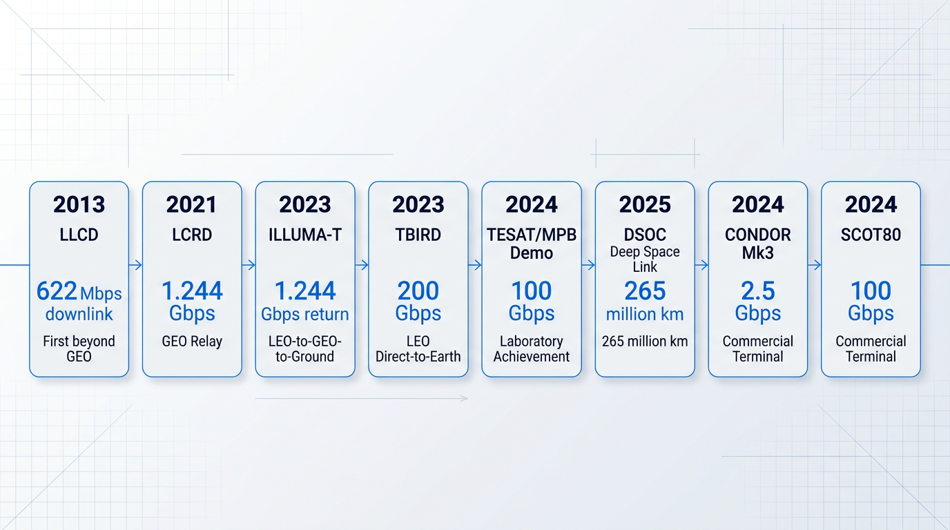
The deep-space frontier was addressed by NASA's Deep Space Optical Communications (DSOC) experiment aboard the Psyche spacecraft. In July 2025, ESA established the first European deep-space optical communication link with DSOC using purpose-built ground stations in Greece, at a distance of approximately 265 million km — completing all four planned links in the summer campaign.
DSOC demonstrates that lasercom is not bounded by near-Earth geometry: the physics that make it compelling for LEO-to-ground and GEO relay applications extend, with appropriate ground segment engineering, to interplanetary distances.
SDA Proliferated Warfighter Space Architecture
If NASA's programme arc proved that lasercom works, the Space Development Agency's Proliferated Warfighter Space Architecture (PWSA) proved that it can be fielded at scale — and in doing so, marked a qualitative shift in the technology's status.
The transition began with Tranche 0, where TESAT terminals aboard SpaceX Tracking Layer satellites demonstrated on-orbit laser link acquisition between satellites — the SDA Director describing it at the time as the final major technical risk item for the broader architecture.
Tranche 1 is the operational realisation: 126 Transport Layer satellites, each equipped with optical communications terminals for satellite-to-satellite and satellite-to-ground laser links, at an average cost of approximately $14 million per space vehicle — a figure that contextualises the scale of investment the US government has committed to lasercom as a primary transport layer.
The PWSA is the first constellation in history where lasercom optical inter-satellite links are the primary communication fabric — not a technology demonstration riding alongside an RF system, but the architecture itself.
The PWSA's scale also created the conditions that made standardisation necessary: when hundreds of satellites from multiple prime contractors must form a coherent mesh network, bespoke terminal designs are no longer viable, and a common interface specification becomes the only workable path.
ESA and European programmes
The operational European counterpart is the European Data Relay System (EDRS) — a GEO relay constellation using Tesat LCT135 terminals that has been quietly demonstrating the durability of lasercom as a production service since EDRS-A entered operation in 2016, with EDRS-C following in 2019.
EDRS supports LEO-to-GEO optical links at up to 1.8 Gbps, with a relay capacity exceeding 50 TB per day, and has surpassed 10,000 laser links established — primarily serving the Copernicus Sentinel Earth observation satellites in near-real time.
EDRS matters as a data point because it is neither a US programme nor a defence application: it is a commercial-facing Earth observation service that has been running reliably for years, demonstrating that lasercom can sustain operational tempo in a civil infrastructure context.
Next-generation capability is already in development: TESAT and MPB Communications demonstrated 100 Gbps at 40 W optical power over a simulated distance exceeding 45,000 km in a laboratory environment in April 2024, targeting the SCOT135 terminal for multi-orbit connectivity scenarios — a 55-fold increase over EDRS's current operational link rate.
ESA's broader ScyLight initiative situates EDRS within a wider European roadmap for optical feeder links and inter-satellite link development, ensuring that EDRS is not a standalone programme but the operational anchor for a continuing European optical communications investment.
The commercial terminal market
The clearest signal of lasercom's commercialisation inflection point is not any single mission result — it is the shift from bespoke, mission-specific terminals to productised, standards-compliant optical communications terminals (OCTs) designed for serial production and catalogue procurement.
Two suppliers define the current market. Mynaric's CONDOR Mk3 is SDA OCT Standard T0/T1 compliant, supports data rates from 0.313 to 2.5 Gbps, and is rated for link distances exceeding 6,500 km. Tesat's SCOT80 is SDA OCT Standard 3.1 compliant, capable of up to 100 Gbps, and has 48 units on orbit across multiple prime contractors.
A terminal that can be selected from a product sheet, ordered against a compliance specification, and integrated by any qualified satellite manufacturer is a fundamentally different commercial object from the bespoke laser terminals that characterised lasercom programmes a decade ago.
That productisation, however, immediately raises the next question: if terminals from different vendors are built to nominally the same standard, can they actually interoperate — with each other, and with the ground infrastructure they need to connect to? That is the question the following section on interoperability standards addresses directly.
Optical ground station infrastructure
Most lasercom engineering literature concentrates on the space terminal — the aperture, the pointing system, the terminal SWaP. But the optical ground station (OGS) is not simply a dish that the satellite points at. It is a precision optical system in its own right, and its design choices constrain the performance of the overall lasercom link just as consequentially as anything on the spacecraft.
OGS architecture: subsystems that make it work
A ground station for lasercom integrates several distinct subsystems that must function as a coherent whole: the telescope, the adaptive optics (AO) system, the uplink transmitter assembly, the beacon laser, the modem, and the site infrastructure.
The telescope sets the aperture available for both transmit and receive. For LEO downlinks, the LCRD OGS-1 at Table Mountain uses a 1-metre aperture, while OGS-2 at Haleakalā operates a 60 cm receive aperture with a separate 15 cm transmit aperture — illustrating how aperture requirements differ between receive-dominated and transmit-dominated roles.
The AO system, as discussed in the context of atmospheric mitigation, serves a dual role: correcting wavefront distortion on the incoming downlink to couple received light efficiently into single-mode fibre, and pre-distorting the uplink beam so that it arrives at the spacecraft with reduced turbulence-induced spreading.
Data flow through the station runs in both directions. On the downlink path, received light from the telescope passes through the AO system and into the detection chain at the modem. On the uplink path, the modem drives the uplink transmitter, which amplifies and formats the signal before it is routed through the AO system and out through the telescope aperture toward the spacecraft.
The beacon laser serves the PAT function described earlier in this guide: it provides the ground-station reference signal that the spacecraft terminal acquires and tracks. A key architectural choice is whether to transmit the beacon and the uplink data channel in separate beams — each requiring its own aperture and alignment path — or to nest both in a single amplified beam, which eliminates that complexity.
Co-transmitting the tracking beacon and uplink data in one beam simplifies the OGS optical train considerably: a single aperture, a single pointing and alignment path, and a single amplifier chain serve both functions simultaneously, reducing the number of precision optical interfaces that must be maintained in the field.
Uplink amplification at 1550 nm
The standard technology for high-power uplink amplification at 1550 nm is the erbium-doped fibre amplifier (EDFA). For operational OGS uplinks, the relevant parameters are output power in the 10 W class, beam quality with M² below 1.1 for diffraction-limited propagation, and the ability to carry both beacon and data modulation in the amplified output.
The 1550 nm band carries a practical safety advantage over 1064 nm: its higher eye-damage threshold allows more flexible site co-location and simplifies some operational procedures. It is important to be clear, however, that at Class 4 power levels, appropriate eyewear and full laser-safety procedures remain mandatory.
Woodrow Scientific Limited's EDFA is an example of a ground-station uplink amplifier built explicitly around the single-beam beacon-and-data architecture: the tracking beacon and uplink data are nested in one amplified beam, with amplitude modulation carrying the beacon tone low and the data signal above it, across three operating modes — acquisition, tracking, and data transmission.
Beyond the single-beam architecture, the amplifier is extensively configurable across both hardware and software layers. Hardware configuration covers band (C-band, L-band, or dual-band from a single source), output power, direction, 2- and 4-emitter array support, an external optical input for third-party transmitters, and cooling. The software layer — WSL's Modulation-on-Demand — provides software-selectable amplitude modulation, waveforms, modulation index, and combined beacon-plus-data modulation, switchable between CCSDS and SDA standards at high power across C/L-band.
This configurability is a genuine engineering requirement rather than a product feature: programmes with long operational lifetimes need ground equipment that can adapt as modulation standards evolve, without requiring hardware replacement every time a standard is updated or a new mission standard is adopted.
The company behind the product is itself a differentiator worth noting. WSL is a UK manufacturer, founded in 2012, that designs, builds, qualifies, and supports its amplifiers entirely in-house on patented technology, with engineering expertise rooted in Southampton's Optoelectronics Research Centre — the institution where the EDFA was originally developed. In a supply chain where many amplifier suppliers are resellers or importers rather than original manufacturers, the practical consequences matter: in-house design capability means genuine engineering support, faster resolution of field issues, and the ability to adapt the product to a programme's specific requirements rather than working around a fixed catalogue specification. CE and UKCA certification is part of the product's complete compliance profile.
As SDA and CCSDS modulation standards continue to evolve, an OGS uplink amplifier that is fixed to a single standard at manufacture creates obsolescence risk for the ground segment. Software-definable amplifiers that can switch standards without hardware replacement are not a convenience — they are a programme-lifetime risk-management tool.
Emitter diversity and site diversity networks
Emitter diversity addresses uplink scintillation by transmitting from multiple sub-apertures or emitters separated by more than the atmospheric coherence length. Because the beams travel through statistically independent turbulence cells, they add incoherently at the spacecraft receiver, smoothing the intensity fluctuations that a single-beam uplink would experience.
Operational OGS designs use 2- and 4-emitter array configurations to achieve this effect. When multiple stations in a site diversity network are synchronised, coordinated emitter diversity transmission across sites becomes possible, combining the benefits of spatial diversity at the emitter level with geographic diversity at the network level.
At the network scale, site diversity requires geographic separation sufficient for cloud cover to be statistically uncorrelated between stations. ESA studies place the strongly correlated cloud-cover radius at approximately 500 km, meaning stations must be separated by at least that order of distance to function as genuinely independent nodes.
Two operational networks illustrate how this principle is applied in practice.
- ESA European ONN: Stations at Tenerife (Spain), Almería (Spain), Nemea (Greece), and The Hague (Netherlands), connected to the KSAT Network Operations Centre in Tromsø.
- NASA LCRD network: OGS-1 at the JPL Optical Communications Telescope Laboratory on Table Mountain, California, and OGS-2 at Haleakalā, Hawaii — sites chosen for complementary weather patterns.
The LCRD network provides a useful data point on what two-station diversity actually delivers in practice: OGS-1 at Table Mountain recorded approximately 57.8% individual availability and OGS-2 at Haleakalā approximately 40.5%, with the sites' weather patterns chosen specifically to complement each other.
JPL analysis of multi-site networks in the continental United States and Hawaii shows that overall link availability of around 90% is achievable with three well-chosen stations, with further improvement possible by extending nodes to additional geographic regions.
Scalability and the path to a flexible ground network
The mission-specific, highly specialised OGS terminal that has characterised lasercom to date is not a viable model for a proliferated LEO constellation of hundreds of satellites. Each such terminal is engineered for a specific mission's wavelength, modulation format, and link geometry; supporting a large constellation requires either a very large number of such terminals or a fundamentally different approach.
NASA's LCOT (Low-Cost Optical Terminal) programme at Goddard Space Flight Center represents the industry's most concrete answer to this challenge. LCOT is built around a 70 cm commercially available telescope and is designed from the outset as a single flexible design that can be quickly reconfigured to support different lasercom missions with little reconfiguration required between them — explicitly intended as a blueprint for a global network of optical ground stations that can grow organically, with terminals built for one mission able to serve future missions.
LCOT's architecture includes four independent 150 mm high-power transmit beam directors alongside the primary receive aperture, an adaptive optics system, and a modular transceiver bench — making it transceiver-agnostic and capable of supporting LEO through lunar distances from a single installation.
The scalability challenge and the standards compatibility challenge are closely linked: a ground terminal that can support multiple missions is only as flexible as the modulation standards its uplink equipment can serve. That connection between ground-segment equipment and the broader question of interoperability standards is precisely what the next section examines.
Lasercom interoperability standards: SDA, CCSDS, and ESTOL
Every lasercom mission from LLCD to LCRD to EDRS defined its own waveform, modulation format, and protocol stack — and that was fine when each link was a standalone demonstration with no expectation of talking to anyone else's hardware. Proliferated deployment changes that calculus entirely.
When dozens of terminals from multiple vendors must interoperate across a shared mesh network, bespoke protocols become a programme liability rather than an engineering convenience. The shift from demonstration to operational deployment — which the SDA PWSA represents at scale — is precisely what has made interoperability standards urgent rather than aspirational.
The SDA OISL and OCT Standards
The SDA OISL Standard (v2.1.2) defines the physical and data link layer requirements for optical links operating within the Tranche 0 constellation, covering both space-to-space links up to 6,500 km and space-to-ground links up to 2,800 km.
The standard specifies required link margins precisely: 3 dB for space-to-space links up to 5,000 km and for space-to-ground links up to 2,800 km, tightening to 1 dB for space-to-space links between 5,000 km and 6,500 km — parameters that directly constrain terminal design choices for anyone building to the standard.
The OCT Standard has evolved rapidly since its initial release: v3.0.1 served Tranche 1, v3.1.0 formalised interoperability specifications for SDA partners, and v3.2.0 was released alongside v4.0.0 as the Tranche 3 record standard, incorporating incremental updates while a select number of terminals comply with v4.0.0's additional requirements.
OCT Standard v4.0.0 introduces a new long-range waveform targeting future MEO connectivity with Space Systems Command Resilient Missile Warning/Missile Tracking satellites — a significant scope expansion that illustrates how the standard is being stretched to meet evolving architecture requirements rather than held static.
Backward compatibility across versions is a stated SDA design goal: v3.2.0 and v4.0.0 are both documented as backward compatible with previous versions, a commitment that signals the agency is actively trying to protect programme investment across tranches rather than forcing hardware replacement at each upgrade cycle.
Above the physical and data link layers sits the NEBULA Standard — formally, the Network Established Beyond the Upper Limits of the Atmosphere — which defines the networking requirements for the Proliferated Warfighter Space Architecture (PWSA) mesh. Version 3.05 was issued in November 2024.
NEBULA is what transforms a collection of point-to-point OCT links into a coherent routable network: it specifies the protocols and behaviours for the space network service, including how space vehicles use Ethernet at the data link layer when communicating between NEBULA links and endpoints within the vehicle. The OCT Standard and NEBULA Standard work together as complementary layers — neither is sufficient alone.
CCSDS Optical Protocols: The Civilian Path
The Consultative Committee for Space Data Systems (CCSDS) Optical Communications Working Group, formed in January 2014, has developed a parallel set of optical standards covering the physical layer, coding and synchronisation, and atmospheric characterisation for free-space optical links.
CCSDS defines three primary signalling regimes: High Photon Efficiency (HPE), which uses pulse-position modulation and targets power-limited long-distance links; Optical On/Off Keying (O3K), a lower-complexity modulation scheme suited to near-Earth scenarios; and a High Data Rate (HDR) specification using phase-shift keying at 1550 nm, targeting LEO-to-GEO and GEO-to-ground links at rates from Mbps to 10 Gbps.
CCSDS standards are contributed to and governed by a consortium of civilian agencies — NASA, ESA, JAXA, CNES, and NICT among them — and represent the natural standardisation path for programmes that operate outside the US DoD acquisition framework. ESA's Optical Nucleus Network explicitly references CCSDS protocols, and ESA has invested in VHDL IP cores implementing the CCSDS 142.0-P-1.1 coding and synchronisation layer for HPE and O3K waveforms.
A third distinct standard has emerged from Europe: ESTOL (ESA Specification for Terabit/sec Optical Links), currently at v2.2, is ESA's specification for high data-rate OISLs and optical ground-to-space links targeting beyond 1 Tbit/s per link through wavelength division multiplexing. Notably, ESTOL's air interface incorporates requirements from the SDA OCT standard — recognising that commercial products have been developed to the OCT standard and that alignment reduces fragmentation — while also drawing on OpenROADM for high-data-rate coherent optics. Contributors to ESTOL include Airbus, Mynaric, Tesat, Thales Alenia Space, and JAXA, among others.
The practical consequence of three distinct standards is not merely a procurement inconvenience. As SPIE and industry sources note, SDA, ESTOL, and CCSDS represent genuinely distinct protocol environments available to terminal manufacturers — and a terminal built natively to the SDA OCT Standard cannot interoperate with a CCSDS-protocol terminal without protocol translation or hardware adaptation.
For programmes that must interface with both the SDA PWSA and civilian or commercial networks — ESA's ONN, NASA's non-defence lasercom infrastructure, or commercial constellations that have adopted CCSDS — this creates a real interoperability risk that propagates through link budget planning, network architecture decisions, terminal procurement strategy, and long-term upgrade paths. ESA's own ONN documentation explicitly acknowledges interoperability concerns arising from the coexistence of CCSDS and SDA standards.
The engineering consequences are concrete: protocol translation overhead adds latency and complexity at network boundaries; procurement teams must specify which standard a terminal must comply with before writing a requirement; and a terminal that is compliant with one standard may require significant rework — or replacement — to operate on a network governed by another.
The OCT Standard has gone through four substantive versions in roughly three years, NEBULA v3.05 arrived in late 2024, and ESTOL continues to evolve as a living document. A terminal whose protocol stack is fixed at the hardware level carries real obsolescence risk in this environment. Software-definability — the ability to reconfigure waveforms and protocol stacks without hardware replacement — is the engineering response to a standards landscape that is demonstrably still in motion.
The clearest evidence that the SDA standards approach works in practice came from a July 2024 demonstration in which a General Atomics OCT mounted on an aircraft and a Kepler Communications satellite in a 500 km orbit successfully completed two-way optical communications — terminals from two different manufacturers, interoperating because both were built to the same SDA standard.
SDA has also established a formal pre-launch compliance mechanism: a hardware-in-the-loop, software-in-the-loop (HIL/SIL) testbed operated by the Naval Research Laboratory (NRL), which validates OISL interoperability across vendor satellites before they are certified for launch — providing a structured path to verify compliance rather than discovering integration failures on orbit.
Standards convergence across SDA, CCSDS, and proprietary waveforms remains an active engineering problem, not a solved one — and it is one of the most consequential open questions in the lasercom field today. The Conclusion draws together this and the other remaining challenges to assess where the technology stands and where the work still lies.
Conclusion
Where lasercom stands today
Lasercom is no longer a technology waiting to prove itself — operational links are in service, and the question has shifted from whether it works to how far it scales.
The live frontier is standards convergence and ground network architecture: choices made now, before a common optical layer solidifies, will shape interoperability for the lifetime of the hardware that carries them.
That is the honest position the technology occupies — genuinely mature, and still mid-evolution in the ways that matter most for long-term programme investment.
Lasercom: frequently asked questions
Precise answers to the questions most likely to remain after reading this guide — covering terminology, wavelength choice, atmospheric constraints, demonstrated performance, spectrum regulation, interoperability standards, and ground station technology.
Lasercom and FSO are the same underlying technology — the distinction is terminological, not technical. Both refer to the use of laser-frequency electromagnetic radiation to transmit data through free space without a fibre or waveguide. The NASA SST-SOA states explicitly: "There are two types of communication systems: radio frequency (RF) and free space optical (FSO) also referred to as laser communications (lasercom)." The SPIE Photonics Focus May/June 2024 article similarly describes lasercom as "also known as free-space optical (FSO) or wireless optical communications." The difference is community of use: lasercom appears predominantly in space and defence literature — NASA, ESA, SDA, and JPL publications — while FSO or free-space optical is the preferred term in the terrestrial wireless community, covering metro area networks, building-to-building links, and 5G backhaul. If you encounter both terms in the literature, they describe the same physics.
Three factors drive the preference for 1550 nm in most near-Earth and LEO lasercom systems. First, mature erbium-doped fibre amplifier (EDFA) technology: EDFAs were developed over decades for terrestrial fibre networks and are commercially available, well-characterised, and high-performance at this wavelength — the same components used in fibre-optic infrastructure can be adapted for space terminals. Second, a significantly higher eye-safety threshold: 1550 nm light is absorbed before reaching the retina, whereas 1064 nm can be focused onto the retina without triggering a protective blink response, creating a much more hazardous exposure scenario. At 1550 nm, eye-safe operation is achievable at orders of magnitude higher power than at 1064 nm. Third, low atmospheric attenuation in the 1550 nm transmission window. A 2000 NASA study selecting the wavelength for a space terminal noted that 1550 nm was chosen for its "eye-safety advantage, better atmospheric transmission, multiple vendor commercial availability, and excellent integrated receivers." 1064 nm retains advantages in specific contexts: silicon avalanche photodiodes (APDs) offer higher detection efficiency at that wavelength, and it is used in some deep-space and OISL terminal designs. The choice is application-dependent, not universal.
No — dense cloud cover causes complete optical link outage. Unlike rain fade for RF, which is a gradual, manageable impairment, cloud attenuation of an optical signal can reach tens of decibels. The JPL Descanso Monograph states directly: "Effective communications through clouds is not a feasible solution as cloud attenuation can be upwards of tens of dB in some cases, and appropriate operational workaround needs to be considered as part of the optical link design." An optical link requires cloud-free line of sight (CFLOS) to operate. The primary engineering mitigation is site diversity: deploying geographically separated ground stations with statistically uncorrelated cloud cover. For an array of stations located in independent weather cells, network availability follows the complement of the joint probability that all stations are simultaneously obscured. A three-station network sited in regions with 20–50% cloud cover probability achieves weather availability of approximately 88–99%. Forward error correction and link margin can help at the margins with thin haze, but they do not address dense cloud blockage. Site diversity is the only operationally proven solution to CFLOS availability requirements.
Four in-orbit milestones mark the progression of demonstrated lasercom performance. 622 Mbps downlink from lunar orbit — NASA LLCD (2013): flying on the LADEE spacecraft, LLCD transmitted error-free data from 400,000 km at 622 Mbps downlink and 20 Mbps uplink, more than six times the then-state-of-the-art RF rate from lunar distance. 1.244 Gbps bidirectional GEO relay — NASA LCRD (operational from 2022): launched December 2021, LCRD demonstrated bidirectional relay at up to 1.244 Gbps between GEO and ground, and subsequently relayed data from the ISS via ILLUMA-T at matching rates, completing NASA's first end-to-end optical relay system. 200 Gbps burst downlink from a LEO CubeSat — NASA TBIRD (2022–2024): a 3U payload on a 6U CubeSat demonstrated 200 Gbps downlinks and transferred more than 1 TB error-free in a single 5-minute pass, reaching a peak of 4.8 TB in one pass — the fastest satellite downlink ever demonstrated. 1.8 Gbps LEO-to-GEO operational relay — ESA EDRS (ongoing): the European Data Relay System's laser communication terminals relay user data from LEO satellites at up to 1.8 Gbps across inter-satellite distances of up to 45,000 km. The progression from 622 Mbps in 2013 to 200 Gbps in 2022 represents demonstrated in-orbit results, not theoretical projections.
No — optical frequencies currently require no ITU or FCC frequency coordination. The ITU Radio Regulations apply to electromagnetic spectrum use below 300 GHz. Lasercom operates at infrared frequencies far above that threshold, so the treaty-level coordination obligations that govern RF communications do not extend to optical bands. The NASA SST-SOA confirms: "Currently there are no licensing requirements for spacecraft laser communications" and "at the present, optical frequencies are unregulated and allow for large bandwidths and high channel throughput." NASA's spectrum guidance document for smallsats states explicitly: "There is no requirement or procedure for the filing of electromagnetic spectrum use above 300 GHz (e.g., laser communication, infrared imaging, or sensing in the ultra-violet regions)." This is a meaningful operational advantage: RF operators must navigate spectrum coordination processes that can involve significant lead time, interference constraints, and band congestion. Lasercom avoids that process entirely. NASA notes it collaborates with international working groups on optical spectrum use, and regulatory frameworks may evolve as deployment scales — but as of now, no coordination is required.
The SDA Optical Communications Terminal (OCT) Standard defines the physical and data link layer requirements that lasercom terminals must meet to be interoperable within the Space Development Agency's Proliferated Warfighter Space Architecture (PWSA). It covers both space-to-space and space-to-ground optical links. The standard matters for two distinct reasons. First, multi-vendor interoperability: the PWSA Transport Layer is procured from multiple contractors, meaning satellites built by different suppliers must be able to form an optical mesh network with each other. Without a common interface specification, each vendor's terminals would only communicate with their own hardware. The OCT Standard makes cross-vendor links possible by specifying the waveform, link margins, and data link requirements at the interface. Second, competitive procurement: any terminal built to the standard can interoperate, which prevents vendor lock-in and sustains a competitive marketplace across constellation tranches. The standard has evolved through multiple versions — v3.1.0, v3.2.0, and v4.0.0 — with v4.0.0 introducing a long-range waveform targeting future MEO connectivity. SDA has also established a hardware-in-the-loop and software-in-the-loop (HIL/SIL) interoperability test laboratory with the Naval Research Laboratory to validate terminal compatibility before launch.
The need for precise pointing, acquisition, and tracking (PAT) arises directly from the physics: at optical wavelengths, beam divergence is on the order of microradians, so a pointing error of even a fraction of a microradian can cause complete link loss. The PAT sequence proceeds in three stages. Acquisition: the ground station transmits an uplink beacon — a wider-field laser signal — that illuminates the spacecraft's expected position. The spacecraft terminal detects this beacon using a wide-field focal-plane array or similar detector, establishing the coarse direction to the ground station. Fine tracking: the terminal transitions to a narrow-field detector — typically a quad-cell or higher-resolution focal-plane array — to track the beacon with sub-microradian precision, continuously measuring the beacon centroid position. Beam pointing: the terminal directs its downlink beam back toward the beacon source using fast steering mirrors, a two-axis gimbal, or spacecraft body-pointing with payload attitude feedback. NASA's TBIRD mission demonstrated a body-pointing architecture achieving approximately 5 µrad RMS pointing stability on a 6U CubeSat, with closed-loop tracking of 20–35 µrad RMS per axis during passes. The JPL Descanso monograph identifies uplink beacon tracking as the standard approach for directing the downlink signal at the ground terminal.
Adaptive optics (AO) serves two distinct roles at a lasercom ground station, one on the downlink and one on the uplink. On the downlink, AO corrects atmosphere-induced wavefront distortions in the received beam before it is coupled into the ground modem's single-mode fibre. Without correction, turbulence-induced phase errors spread the beam across the focal plane, causing severe coupling loss — the JPL LCRD ground station (OGS-1) AO system targets a coupling efficiency above 55% (Strehl ratio ~70%) under median seeing conditions at Table Mountain. The system uses a Shack-Hartmann wavefront sensor and a woofer-tweeter deformable mirror arrangement to correct both low-spatial-frequency, large-amplitude aberrations and high-spatial-frequency, small-amplitude errors. On the uplink, AO can pre-distort the transmitted wavefront to partially pre-compensate atmospheric turbulence, reducing beam wander and improving irradiance at the spacecraft aperture. Two important limitations apply. First, AO does not correct full-aperture tilt — tip-tilt must be handled by a separate control loop, because a laser guidestar experiences the same tip-tilt on the uplink as the downlink, making it an unreliable tilt reference. Second, AO correction is spatially limited by the isoplanatic angle and temporally limited by the turbulence bandwidth, so performance degrades at low elevation angles and under strong turbulence conditions.