

Introduction
If you're an engineer, maintenance manager, or technical professional evaluating laser cleaning for a real application, this walkthrough is written for you.
You'll leave with more than a description of what laser cleaning is — you'll understand what physically happens at each stage of the process, and why those physics produce the results they do.
The article is structured as five ordered steps, running from initial surface assessment through to post-clean inspection, so you can follow the process as it actually unfolds.
Laser cleaning has become a serious tool across industrial maintenance, precision manufacturing, and heritage restoration — and the reasons for that become clear once you understand the process properly.
TL;DR
Laser cleaning works precisely because of the physics involved, not in spite of them. The contaminant is removed; the substrate is not. Every outcome — good or poor — traces back to how well the process parameters were matched to the material at hand.
This article covers:

The physics of laser ablation in plain language
Step-by-step walkthrough: surface prep to inspection
How laser parameters affect cleaning outcomes
Process differences by contaminant and substrate
What Is Laser Cleaning?
Laser cleaning is a surface treatment process that uses focused, pulsed laser energy to remove contaminants from a surface through laser ablation — no mechanical contact, no abrasive media, no chemicals required.
What makes the process physically distinctive is not the laser itself but the principle it exploits: different materials absorb laser energy at different rates, and that difference is what separates the contaminant from the substrate.
Selective Absorption: Why the Contaminant Goes
Contaminants such as rust, paint, and oxide layers absorb laser energy at a significantly higher rate than the underlying base metal beneath them.
This difference in optical absorption is the foundation of selective absorption — the laser preferentially heats the contaminant layer while the substrate, absorbing far less energy, remains largely unaffected.
The laser is not blindly blasting the surface; it is exploiting a material property difference that already exists between the contaminant and the substrate.
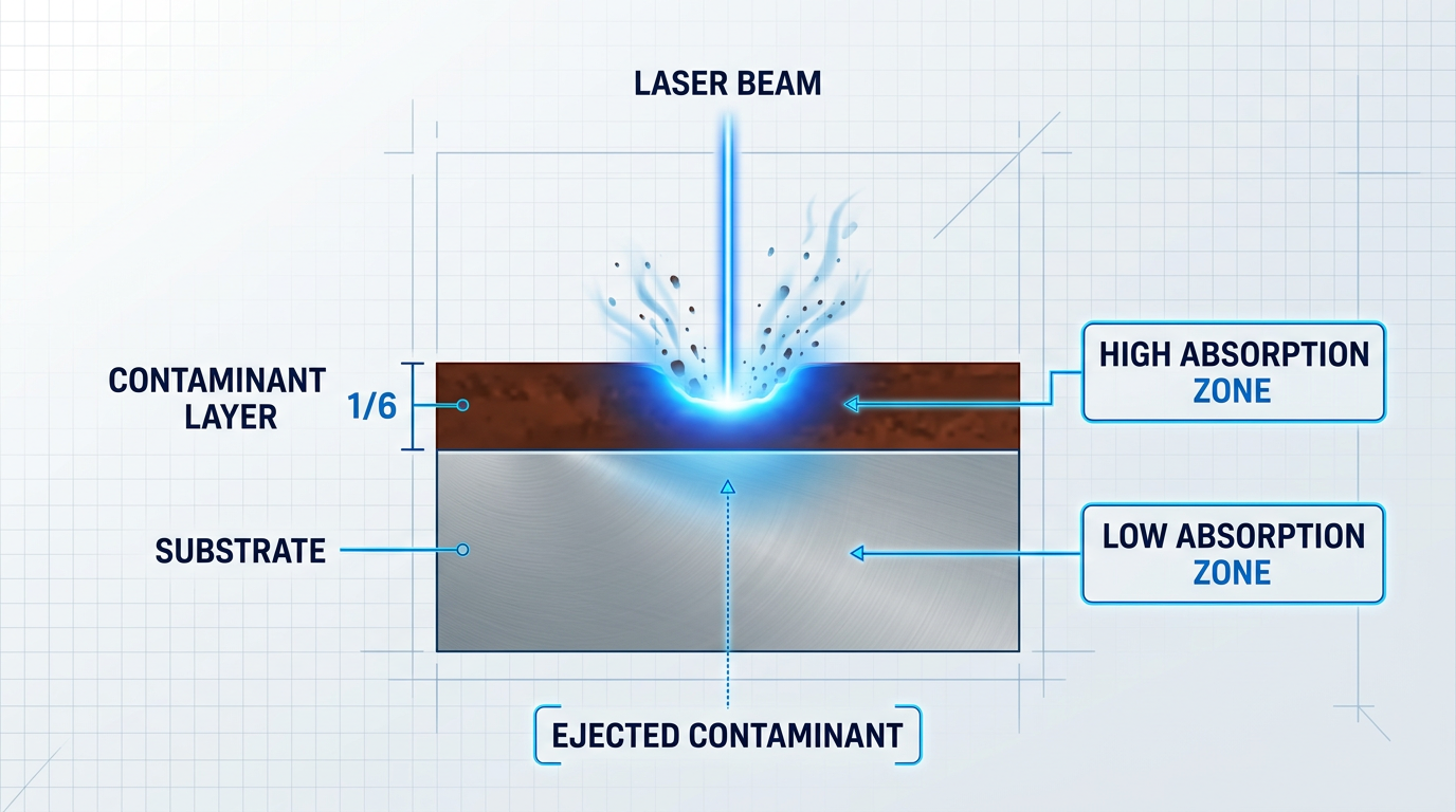
Once the contaminant absorbs sufficient energy, removal happens through one of two mechanisms: vaporisation or spallation.
In vaporisation, the contaminant absorbs energy so rapidly that it converts directly to vapour or plasma — it is gone before it has any meaningful opportunity to transfer heat to the substrate below.
In spallation, rapid thermal expansion at the contaminant-substrate interface breaks the adhesion bond and ejects the contaminant as solid particles, rather than vapour — the shock of expansion does the mechanical work of detachment.
Every material has a minimum energy density — its ablation threshold — required to ablate it. Effective laser cleaning operates above the contaminant's ablation threshold but below the substrate's ablation threshold. This gap between the two thresholds is the operating window, and it is what makes the process controllable.
Understanding the ablation threshold is essential before any parameter is set: the contaminant and substrate each have their own threshold, and the operating window between them is the space in which the process works safely.
The energy density delivered to the surface — known as fluence — must be tuned to sit within that window, which is why knowing the specific contaminant and substrate material is not optional preparation but a prerequisite for every parameter decision that follows.
Why Pulsed Operation Is the Standard
Pulsed laser operation is the dominant mode for precision laser cleaning because short, high-energy pulses deliver energy to the contaminant faster than the substrate can conduct it away.
The contaminant heats and ablates before the thermal energy has time to diffuse into the base material — and between pulses, the surface cools, resetting the thermal state before the next pulse arrives.
This inter-pulse cooling interval is the physical mechanism that protects the substrate, and it is the reason pulsed operation is technically preferred for applications where surface integrity matters.
Continuous wave (CW) mode delivers energy without interruption, which causes heat to accumulate in the surface over time — eliminating the cooling benefit and making substrate damage progressively more likely as the pass continues.
For most precision cleaning applications, CW is the less suitable choice: it trades the controllability of the pulsed operating window for throughput, at the cost of the substrate protection that defines the method.
The result of a correctly executed laser cleaning pass is a surface with the base material's profile and dimensions largely preserved — unlike sandblasting, which introduces new surface texture through abrasive impact, or chemical stripping, which requires waste handling and direct chemical contact with the substrate.
With this physical foundation in place, the practical question is how an operator actually applies it — starting with what needs to be assessed and prepared before the laser is ever switched on.
Step 1
Assess the Surface and Prepare the Work Area
Key Insights
Identify substrate and contaminant before adjusting any settings.
Fume extraction is mandatory, not optional.
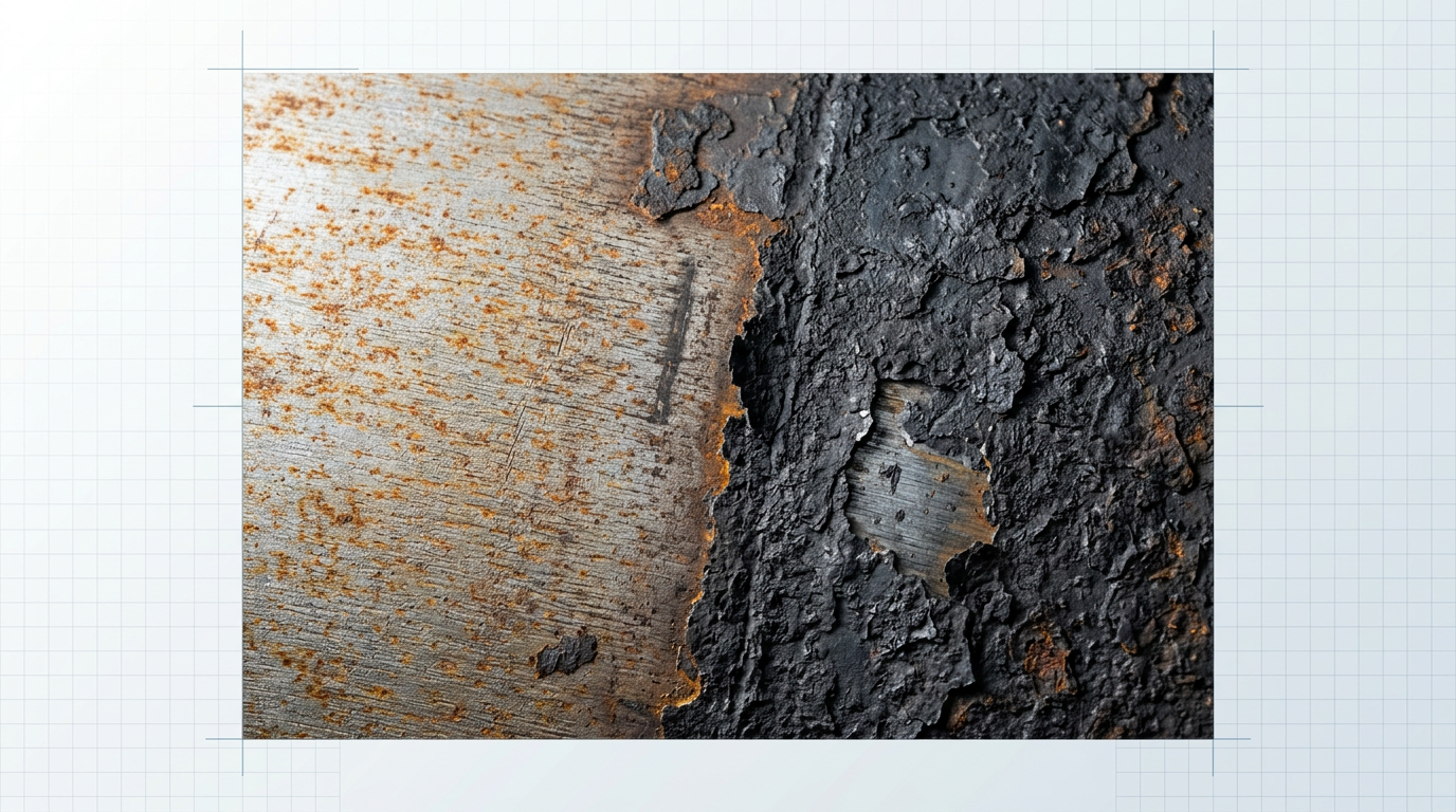
Before the laser is powered up, identify two things: the substrate material (steel, aluminium, cast iron, stone, masonry, or other base) and the contaminant type (rust, paint, oxide layer, grease, mill scale, soot, or similar).
These two factors are the direct inputs to every parameter decision in Step 2 — the substrate material determines where the ablation threshold sits, and the contaminant type determines how much energy is needed to exceed it without touching the base material.
Next, assess the condition and extent of the contamination, not just its type.
Light surface rust behaves differently from heavy mill scale; a single-layer primer coat is a different challenge from a multi-layer paint system built up over years. This assessment shapes whether you will need a single pass at moderate fluence, multiple passes at adjusted settings, or a high-fluence first pass followed by a lighter finishing pass — decisions that belong to Step 2, but which you cannot make without this groundwork.
Fume Extraction and Work Area Readiness
Laser ablation vaporises contaminants and ejects fine particles, including nanoparticles in the 50–200 nm range that can cross the lung-blood barrier. Fume extraction is a process requirement, not an optional enhancement — confirm your extraction system is set up and drawing correctly before the clean begins.
The byproducts vary by material: metal processing releases heavy metal dusts (nickel, cobalt, chromium from alloyed steels); organic coatings can release VOCs including benzene and toluene; virtually all materials produce some form of respirable particulate. Adequate ventilation must reduce fumes and vapours to levels below applicable threshold limit values, as required by OSHA and equivalent national standards.
With extraction confirmed, check the work area itself: the surface must be dry and free of loose debris, and the surrounding zone must be clear of flammable materials within the beam hazard area.
Laser Safety Perimeter and PPE
Industrial laser cleaning systems typically operate as Class IIIB or Class IV lasers, both of which require a defined laser controlled area that encompasses the Nominal Hazard Zone (NHZ) — the space within which direct, reflected, or scattered radiation exceeds the Maximum Permissible Exposure.
- Establish the controlled area: Restrict access to authorised personnel only. Post the required DANGER warning signage at all entry points.
- Fit laser-rated eye protection: All personnel within the controlled area must wear eyewear appropriate to the system's output wavelength and power class, labelled with optical density values. Per OSHA directive STD-01-05-001: laser eyewear must be on before the laser can be turned on.
- Cover windows and open portals: Ensure any windows, doorways, or open portals are covered or restricted to reduce transmitted beams below the applicable MPE level.
- Position the beam path safely: Secure the laser so the beam path runs above or below eye level in both standing and seated positions.
These controls are standard industrial practice for any Class IIIB or IV laser operation — the same category of precaution as ventilation requirements in a spray booth. With them in place, laser cleaning is a well-managed process.
Before moving to Step 2, confirm: substrate material identified, contaminant type and condition assessed, fume extraction running, laser-rated PPE on all personnel, safety perimeter and signage in place, work area dry and clear of flammables. Every parameter decision in Step 2 depends on what you have established here.
Step 2
Select and Set Laser Parameters
Key Insights
Stay within the fluence operating window.
Balance scan speed against pulse frequency.
Default to pulsed mode for precision cleaning.
Match fluence to contaminant severity.
With your surface assessment complete, you now have the two inputs that drive every parameter decision: the substrate material and the contaminant type and severity.
Work through the three core parameters in sequence — power level, pulse frequency, and scan speed — because each one constrains the next.
Set Power Level (Fluence)
Power level determines fluence — the energy delivered per unit area of surface — and fluence is the parameter that either removes the contaminant or damages the substrate, depending on where you set it.
The target is an operating window: fluence high enough to exceed the contaminant's ablation threshold, but low enough to stay below the substrate's damage threshold, as established in the physics background.
Set power higher for thick, tenacious contaminants such as heavy rust or mill scale on steel; set it lower for thin oxide layers or delicate substrates where the damage threshold sits closer to the cleaning threshold.
Set Pulse Frequency (Repetition Rate)
Pulse frequency controls how many pulses strike the surface per second — and with it, how much heat accumulates between pulses.
Higher frequency increases cleaning speed, but the shorter interval between pulses allows less time for the surface to cool, raising the risk of thermal buildup in the substrate.
For heat-sensitive substrates — aluminium alloys, thin-gauge steel, or any material with a damage threshold close to the cleaning threshold — reduce frequency to extend the inter-pulse cooling interval and protect the base material.
Set Scan Speed Relative to Frequency
Scan speed governs how long the beam dwells at any given point on the surface: too slow and the substrate absorbs excess cumulative energy; too fast and coverage becomes incomplete, leaving untreated patches.
These two parameters are interdependent. The scan speed determines how many pulses land on each point of the surface — which is only meaningful relative to the pulse frequency you have already set. Increase frequency without increasing scan speed and you overdose the surface; increase scan speed without adjusting frequency and you underdose it. Set them as a pair, not in isolation.
Once scan speed is set here, you will actively monitor and manage beam traversal during the scanning pass in Step 3 — so treat this as your starting value, not a fixed one.
Choose Pulsed or CW Mode
For the vast majority of laser cleaning applications, use pulsed mode — nanosecond pulses deliver energy to the contaminant faster than the substrate can conduct it away, exploiting the differential absorption principle to remove the coating while leaving the base material intact.
CW (continuous wave) or modulated-CW mode can achieve higher throughput on certain thick coatings, but it sacrifices the inter-pulse cooling interval that protects the substrate — making it a throughput compromise rather than a precision tool.
Reserve CW or modulated-CW for scenarios where the substrate is robust, the coating is heavy, and throughput is the priority; default to pulsed mode for everything else.
Translate Contaminant Type into Parameter Direction
Use the contaminant identified in Step 1 to set your starting parameter direction before fine-tuning on a test patch.
| Contaminant | Substrate | Fluence | Frequency | Mode |
|---|---|---|---|---|
| Heavy rust / mill scale | Steel | Higher | Moderate to high | Pulsed |
| Paint / organic coatings | Steel / cast iron | Moderate | Higher | Pulsed |
| Light oxides / tarnish | Aluminium / non-ferrous | Lower | Lower | Pulsed |
| Thick coatings (high throughput) | Robust steel | Higher | High (CW) | CW / modulated-CW |
| Soot / carbon deposits | Mixed | Lower to moderate | Moderate | Pulsed |
Gives the operator a quick-reference guide to translate contaminant type directly into parameter direction. Directional rather than prescriptive, so it remains valid across different system power levels.
These are directional starting points — always verify on a small test area before committing to a full cleaning pass, particularly on unfamiliar substrate and contaminant combinations.
Systems with fully tunable power and adjustable repetition rates give you the flexibility to dial in precisely within this window: our portable system, the ELASER, offers 0–100% power tunability and a pulse repetition rate adjustable up to 200 kHz, meaning a single unit spans light oxide removal through to thick coating stripping without hardware changes.
See the Parameters in Action
You now understand the settings that drive laser cleaning. See how those parameters translate into a real machine — full specifications, power options, and operating ranges.

Step 3
Scan the Beam Across the Surface
Key Insights
Control overlap and standoff.
Watch the ablation plume.
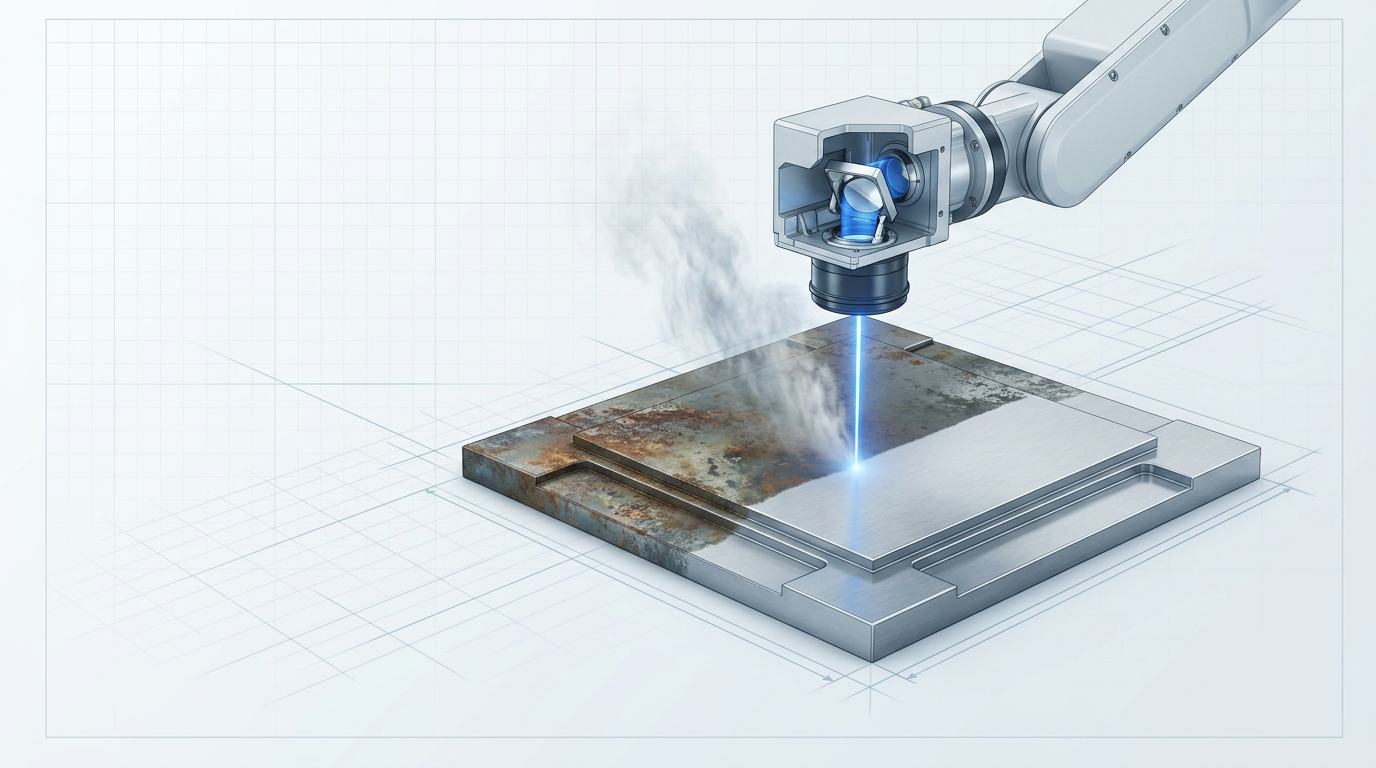
Inside the laser head sits a 2-D galvanometer scanner: a pair of rapidly rotating mirrors that deflect the beam across a defined field without the head itself moving for every millimetre of coverage.
The scanner handles coverage within each head position; you move the head — or the robotic arm moves it — to tile across the full work area.
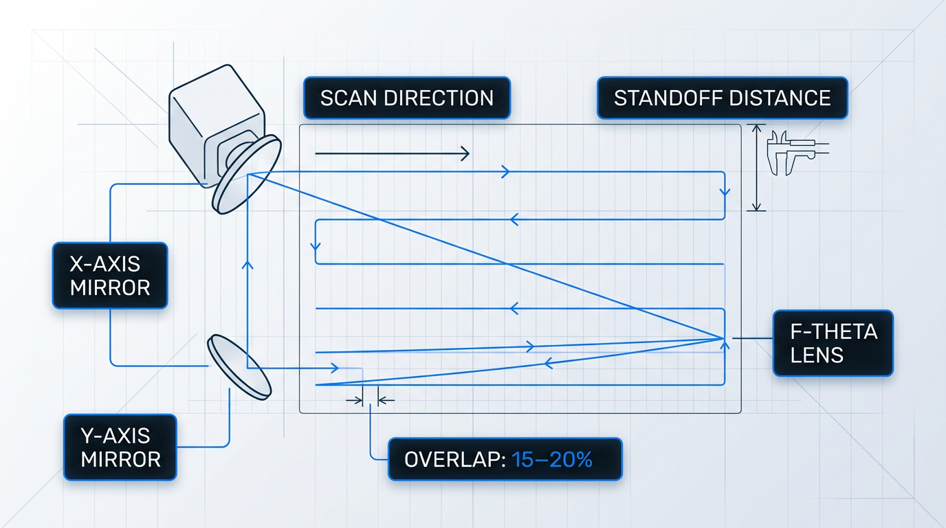
With parameters set in Step 2, verify your scan overlap before committing to the full pass.
Adjacent scan lines must overlap sufficiently to ensure complete, uniform coverage: gaps between passes leave untreated strips that will require re-passes, while excessive overlap accumulates heat and risks pushing cumulative fluence above the substrate's damage threshold.
The correct overlap is a direct product of the spot size, scan speed, and pulse frequency you configured in the previous step — if any of those change, recalculate before proceeding.
Maintain standoff distance throughout the pass
The F-theta lens focuses the beam at a fixed working distance from the surface, producing a uniform spot size across the entire scan field.
If the head drifts closer or further from the surface, the spot size changes — and with it, the energy density (fluence) delivered at that point.
A drift upward drops fluence below the contaminant's ablation threshold; a drift inward can push it above the substrate's damage threshold — either way, you leave the safe operating window established by your parameters.
Maintain a consistent standoff distance throughout every pass, particularly when working over curved or uneven geometry.
Handheld operation: match your traverse speed
For handheld operation, move the head at the traverse speed programmed in Step 2 — steady, consistent movement is the single most controllable variable in a manual pass.
Uneven movement creates dwell spots: areas where the beam lingers longer than intended, accumulating energy locally and potentially pushing fluence above the substrate's damage threshold.
A lightweight handheld scanner helps here — the ELASER's scanner weighs under 3 kg with up to 50 m of delivery cable, giving a single operator the reach and control to hold a steady pace across large or awkward structures.
Automated systems: path generation without manual input
For automated systems, the scanning head follows a pre-programmed or machine-vision-generated path, delivering consistent coverage across complex 3D geometries without manual traversal.
The AutoLASE takes this further: load the part and its machine-vision software scans it, builds a 3D map, and generates the cleaning path automatically — no manual path-setting or knowledge of part geometry required.
Both modes are valid for different applications; the choice depends on part geometry, batch size, and whether the work is in-situ or on a dedicated cell.
Monitor the ablation plume as you scan
During the scan, watch the ablation plume — the visible smoke and vapour produced as the laser interacts with the contaminant.
A steady, uniform plume across the pass confirms that parameters are being applied consistently. An irregular or absent plume in a section signals a standoff or focus issue at that point — stop, correct the standoff, and re-pass that area before continuing. Also confirm fume extraction is active and drawing correctly throughout the scan.
Step 4
Ablation and Contaminant Ejection
Key Insights
Differential absorption protects your substrate.
Aluminium has a narrower margin than steel.
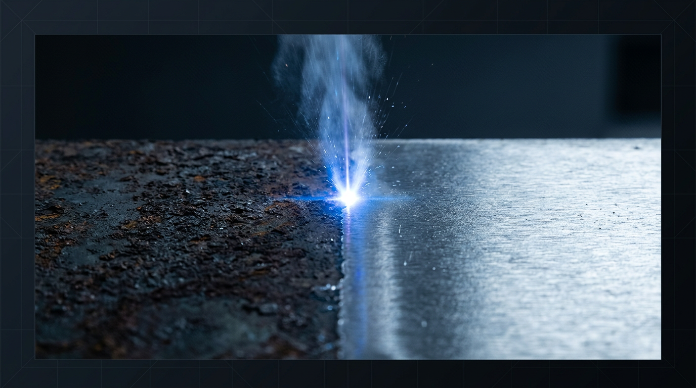
As the beam traverses the surface, two distinct removal mechanisms are at work — and you can read which one is dominant by watching the plume and the debris character during the pass.
Direct vaporisation handles thin oxides and organic coatings: the contaminant absorbs the pulse energy so rapidly that it transitions directly to vapour, producing the characteristic fine, luminous plume you see rising from the work area. Spallation drives thicker or more adherent contaminants: rapid thermal expansion at the contaminant-substrate interface breaks the adhesion bond, ejecting particles and flakes rather than vapour.
What protects your substrate during this process is the differential absorption established earlier: at the ~1070 nm wavelength of industrial fibre lasers, iron oxides, organic coatings, and carbon deposits absorb laser energy strongly, while bare steel and aluminium reflect a significantly higher proportion. The contaminant takes the energy; the base material is largely spared.
Differential absorption protects your substrate while contaminant is present. As the contaminant clears and bare metal is exposed, that margin narrows. Watch the surface actively throughout the pass and be ready to adjust.
How this plays out in practice depends on what you are cleaning. The four most common industrial scenarios each have a distinct behaviour pattern to recognise.
| Material / Contaminant | Primary Mechanism | Fluence Guidance | Key Watch-Out During Pass |
|---|---|---|---|
| Rust and mill scale on steel | Vaporisation (thin rust) and spallation (mill scale) | Higher fluence appropriate; iron oxide absorbs strongly relative to bare steel | As rust clears, bare metal is exposed — reduce fluence or increase scan speed at the transition point to avoid over-treating the substrate |
| Paint and organic coatings | Vaporisation; spallation at the coating-substrate interface for thicker films | Moderate fluence at higher repetition rates; multilayer systems may need multiple passes | Re-assess parameters between passes on thick multilayer coatings — each layer may respond differently |
| Aluminium alloys | Vaporisation of oxide layer | Lower energy density required; aluminium's higher thermal conductivity and lower ablation threshold narrow the safe operating window | The margin between oxide removal and substrate damage is tighter than on steel — parameter discipline is critical here |
| Stone and masonry (heritage/restoration) | Photomechanical effects; differential absorption between soiling or biological growth and the substrate | Parameters must be validated on a test area before committing to a full pass | Context shift from industrial metalwork — caution level is appropriately higher; do not skip test validation |
Four substrate/contaminant pairings compared across consistent axes — primary mechanism, fluence guidance, and the key watch-out during the pass. A table communicates these comparisons more clearly and efficiently than four separate prose blocks.
Across all four scenarios, the ablation plume should remain consistent in character throughout the pass — a change in plume density, colour, or particle size is a signal that surface conditions are shifting and your parameters may need adjustment.
Confirm your extraction system is active and running throughout the pass — it is capturing vaporised material and ejected particles in real time, and any interruption in extraction means those byproducts are no longer being controlled.
Step 5
Inspect the Cleaned Surface
Key Insights
Read the surface visually.
Diagnose before you re-clean.
Stop at the cleaning endpoint.
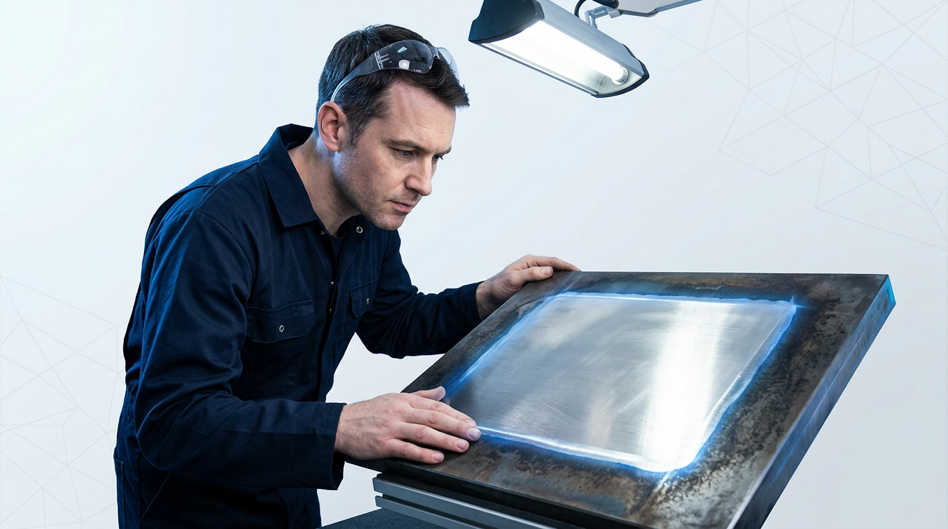
The cleaning pass is complete — now confirm it worked. Inspect the full treated area under adequate lighting before the surface moves to its next process step.
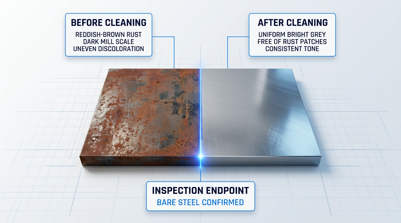
A correctly cleaned surface has a distinct appearance that varies by substrate — learn to read these visual signals rather than relying on pass count alone.
- Bare steel: Uniform bright metallic grey, free of reddish-brown rust patches or dark mill scale. The surface should look consistent in tone across the entire treated zone, with no residual discolouration.
- Aluminium: Clean, matte silver-white with no dark oxide streaking or patchy dullness. The cleaned area should be visually uniform; any remaining dark patches indicate incomplete oxide removal.
- Stone and masonry: The original substrate colour and texture should be restored, with biological growth, soot, or crust fully absent. Look for consistent texture across the treated area — uneven pitting or residual darkening signals incomplete coverage.
Work across the surface systematically under a direct light source, angling it to catch surface texture. Look for residual patches, uneven coverage at scan edges, and any discolouration that extends beyond the original contaminant zone.
If patches of contamination remain, identify the cause before taking corrective action — the fix depends entirely on which problem you have.
Diagnosing Residual Contamination
A coverage gap produces isolated missed patches with sharp boundaries that correspond to the scan pattern — the laser passed cleanly elsewhere but didn't reach these areas. Correct it with a targeted pass over the missed zones, not a full re-clean.
A parameter insufficiency produces a more diffuse result: the contaminant is partially thinned or lightened across the whole area but not fully removed, because the fluence was below the contaminant's ablation threshold. Correct it by adjusting parameters upward and repeating the full pass.
Treating a coverage gap as a parameter problem — and raising power across the whole surface — risks over-treating areas that were already clean. Identify which problem you have first.
Once bare substrate is visible, the cleaning endpoint has been reached. Running additional passes at the same parameters over already-clean areas pushes past the substrate's ablation threshold, causing micro-pitting and surface roughening. More passes do not equal more clean — they equal substrate damage. Stop at exposure, not at confidence.
For applications with formal cleanliness requirements — pre-weld preparation, coating adhesion, structural bonding — verify the cleaned surface against the relevant specification. Laser cleaning is capable of achieving high cleanliness grades comparable to abrasive blasting, making it suitable for demanding downstream processes.
For steel surfaces proceeding to welding, coating, or bonding, move to the next process step without unnecessary delay. Laser cleaning leaves a dry, active surface, and steel in particular can begin to re-oxidise if left exposed.
Ready to Put Laser Cleaning to Work?
You understand the process. The next step is seeing the right machine for your application. Explore our laser cleaning systems or speak directly with an expert about your specific requirements.
Conclusion
Laser cleaning in practice: what you now understand
What you have now is more than a process description: it is an understanding of why laser cleaning produces the results it does — because selective absorption does the discriminating work, and deliberate parameter selection is what puts that physics to use.
That principle is what separates laser cleaning from every method that removes material indiscriminately. The contaminant goes; the substrate stays. That outcome belongs to the operator who understands the process well enough to set it up correctly.
The natural next question is which system suits your specific application — and that is worth evaluating with the same rigour.
Laser cleaning: frequently asked questions
Answers to the questions readers most commonly ask after learning how the laser cleaning process works.
Laser cleaning uses selective photothermal ablation — the laser energy is absorbed preferentially by the contaminant, which vaporises or spalls away without any mechanical contact and without consumables. Sandblasting uses abrasive mechanical impact, which cleans and roughens the surface simultaneously, regardless of whether roughening is wanted. The practical consequence is significant: laser cleaning preserves the substrate's dimensional profile and surface tolerances, while sandblasting creates an anchor profile that is useful for paint adhesion but problematic wherever tight tolerances must be maintained or the base material must not be altered. Laser cleaning also produces no secondary abrasive waste stream and requires no chemicals — the only by-product is the extracted fume and fine particulate from the ablated contaminant.
Laser cleaning removes a wide range of surface contaminants, including rust, mill scale, paint, powder coating, lacquer, primer, oil and grease, carbon and soot, oxide layers, weld discolouration, adhesive residues, release agents, and graffiti. The governing principle is optical absorption contrast: contaminants that absorb the laser wavelength strongly relative to the base material are removed most selectively and cleanly. Where that contrast is high — rust on steel, for example — the process is highly precise. Where it is lower, parameters need closer attention to stay within the safe operating window.
Yes, it can — if parameters are set incorrectly. Every material has an ablation threshold: a minimum energy level required to ablate it. Correctly set parameters keep the process above the contaminant's threshold but below the substrate's, which defines the safe operating window. The risk is highest at the cleaning endpoint, when the contaminant layer has cleared and bare metal is receiving the full beam energy without the contaminant acting as a buffer. At that point, reducing fluence or increasing scan speed is the appropriate response. Signs of substrate over-treatment include micro-pitting, surface roughening, and discolouration extending beyond the original contaminant zone — all of which are detectable during the Step 5 visual inspection.
Yes, materially more so than chemical stripping or abrasive blasting. Laser cleaning requires no chemicals, no abrasive media, and produces no wastewater. The only waste stream is the extracted fume and fine particles captured by the fume extraction unit — a fraction of the spent abrasive or chemical bath waste generated by traditional methods. Fume extraction is required and adds to setup, but the total waste volume is substantially lower. On energy consumption, laser cleaning's operating power draw per hour is lower than many blast or chemical processing methods, contributing further to a reduced environmental footprint.
Yes. Laser cleaning works reliably across a wide range of industrial and restoration applications. The physical basis for its reliability is selective absorption: the contaminant absorbs the laser energy and is vaporised or ejected, while the base material — absorbing less energy at the same wavelength — is largely preserved. This is not a marginal effect; it is the fundamental mechanism, and it holds consistently when parameters are set within the operating window (above the contaminant's ablation threshold, below the substrate's). The process is proven across rust removal, mill scale stripping, paint and oxide removal, weld preparation, and heritage conservation, with results that are repeatable and inspectable after every pass.
Laser cleaning has several genuine trade-offs worth understanding. Area coverage rate is lower than sandblasting for large structural surfaces — it is a precision method, not a bulk-throughput one. It cannot address deep pitting corrosion: the laser removes surface contamination but cannot fill or reshape a pit profile left by corrosion. Highly reflective materials such as bare copper require specialised parameter care, as their low absorption at typical fibre-laser wavelengths narrows the operating window considerably. Fume extraction is mandatory — vaporised contaminants and ejected particles must be captured, which adds to setup requirements. Finally, laser safety measures must be observed: appropriate PPE and a defined hazard zone are required for all operators. Each of these is a manageable consideration with proper setup and training, not a fundamental barrier to use.