

Introduction
The satellite communications industry is genuinely moving toward optical laser links — but the transition is uneven, orbit-regime-specific, and nowhere near complete.
Most coverage of this shift reads like a technology celebration: optical wins on bandwidth, spectrum, and security, full stop. That framing is incomplete, and for engineers evaluating real architectures it can be actively misleading.
The optical-vs-RF question is an application-engineering problem. The right answer follows from mission requirements — orbit regime, availability budget, ground-segment constraints — not from following a technology trend.
TL;DR
Optical laser links are the clear winner in vacuum environments and high-throughput relay — but atmospheric constraints, pointing complexity, and ground infrastructure costs mean RF remains rational for many mission types. Hybrid optical-RF architectures are not a compromise; for most operators today, they are the mature, pragmatic answer.
This article covers:

Why LEO inter-satellite crosslinks switched to optical first
Atmospheric and PAT friction in satellite-to-ground optical links
Where RF remains the rational primary link choice
How hybrid optical-RF architectures work in practice
Spectrum, security, and regulatory dimensions of the decision
The trade-off across orbit regimes and mission types
Satellite Optical Communications: Strengths, Limits, and RF's Edge
The case for satellite optical communications is compelling enough that major space programmes are committing serious capital to it — yet the engineers closest to those programmes are careful not to frame it as a straightforward replacement for RF.
Free-space optical (FSO) communications transmits data using laser light rather than radio waves, operating typically in the near-infrared around 1550 nm. Three consequences of that choice drive all the industry interest: extremely narrow beams, access to vastly more spectrum, and no licensing requirement from the ITU Radio Regulations framework.
On spectrum, the gap with RF is not marginal — it is structural. According to NASA NTRS 20070017310, Ka-band RF systems operate with a bandwidth of typically 500 MHz, while optical systems at 1.55 µm have access to bandwidth approximately 1,000 times larger. A separate NASA laser communications analysis puts the available optical channel bandwidth at around 2 THz for a single wavelength — a regime that makes Tb/s data rates physically achievable in a way that Ka-band architectures simply cannot approach at equivalent mass and power.
That spectral abundance is also unregulated. As confirmed by the ITU Radio Regulations (Vol. 1, 2024 edition), radio waves are defined as electromagnetic waves with frequencies below 3,000 GHz — optical communications at 193 THz (1550 nm) sits well beyond that boundary and, as NASA's SmallSat Systems Technology State of the Art publication explicitly states, optical frequencies are currently unregulated, with no licensing process equivalent to that governing RF spectrum.
The same beam narrowness that makes optical so spectrally and power-efficient also imposes a severe engineering burden. NASA technical work dating from the late 1980s through to current missions consistently establishes that optical links require submicroradian pointing precision — a 1991 NASA/Goddard report on the Pointing, Acquisition and Tracking System (PATS) describes the requirement as pointing accuracy at the submicroradian level, noting that open-loop pointing uncertainty of 1–10 mrad typical of space platforms must be reduced to below 1 µrad via closed-loop tracking.
The ESA SILEX/ARTEMIS programme put real numbers on what that means operationally: tracking error on the OPALE terminal was demonstrated at 0.12–0.19 µrad (1σ) per axis, with a communication beam divergence of only 8 µrad — several orders of magnitude narrower than the open-loop pointing accuracy of a typical orbital platform.
That same narrow beam is also what makes optical links inherently difficult to intercept — the small beam footprint at the receiver means low probability of intercept (LPI) is a structural property of the link, not an add-on security feature.
Where RF Retains Genuine, Durable Advantages
RF's advantages are not temporary limitations waiting to be engineered away — they reflect the physics of longer wavelengths and decades of operational investment.
The most consequential RF advantage is atmospheric penetration. Clouds, rain, and fog that would interrupt an optical link have negligible effect on Ka-band and lower RF bands under most conditions. A NASA deep-space architecture paper is explicit on this point: maintaining a Ka-band capability enables high-rate communications to continue in the presence of clouds, when optical is not possible.
RF also benefits from mature global ground infrastructure built over decades — antenna networks, operational protocols, and spectrum coordination frameworks that are proven, standardised, and widely available. An operator choosing RF today inherits that heritage; an operator choosing optical must build or contract ground infrastructure that is still maturing.
The pointing requirement difference is also orders of magnitude, not incremental. Where optical demands submicroradian closed-loop tracking precision, RF beams are wide enough that acquisition and tracking are comparatively straightforward — a fundamental operational asymmetry that matters most in dynamic, multi-node, or rapidly-deployed mission architectures.
Optical communications' bandwidth and spectrum advantages materialise fully only when atmospheric availability is managed, pointing engineering is mature for the platform, and sufficient ground infrastructure is in place. None of these conditions is free, and none is universally met — which is why the optical-vs-RF decision is always application-specific.
This conditionality is the core analytical point that separates a serious trade-off analysis from a simple technology ranking. For inter-satellite links operating in vacuum, atmospheric availability is irrelevant and pointing engineering is the only constraint. For LEO-to-ground links, cloud cover becomes a real availability driver. For GEO feeder links, both atmospheric availability and ground infrastructure density shape the economics. The technology does not change — the application context determines whether its advantages materialise.
Evaluating any specific mission therefore requires working through a set of practical questions: What orbit regime and link geometry apply? What mission type — commercial broadband, government or defence, scientific — sets the availability and data rate requirements? What is the link availability budget the mission can tolerate? What data rate does the payload actually need? What latency constraints apply to the architecture? And what ground-segment investment is feasible?
Those six axes — orbit regime, mission type, link availability requirement, data rate, latency budget, and ground-segment constraints — structure the analysis that follows, starting with the context where optical's case is most clear-cut: inter-satellite crosslinks in LEO, where the atmosphere is not a factor and the bandwidth advantage is uncontested.
Step 1
LEO Inter-Satellite Crosslinks: Where Optical Has Already Won
Key Insights
Vacuum eliminates optical's main weakness; mass-power economics seal the case.
All four major LEO constellations have committed to optical ISLs.
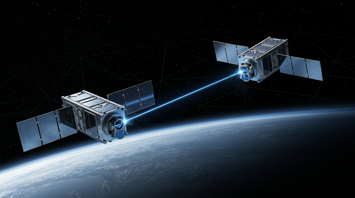
The foundational reason LEO inter-satellite links represent the clearest win for satellite optical communications is environmental: LEO-to-LEO links operate entirely in vacuum, which means the atmospheric availability problem — the dominant reliability constraint for every satellite-to-ground optical link — simply does not exist on this path.
That single fact changes the engineering calculus completely, and the bandwidth-per-kilogram argument compounds it further.
At LEO, every kilogram and watt on a satellite bus competes directly with payload capacity and launch cost — constellation economics are acutely sensitive to mass and power budgets in a way GEO programmes are not.
Optical ISL terminals deliver substantially higher crosslink throughput at lower mass and power than equivalent RF crosslinks, and that gap is not marginal: it is the kind of trade-off that determines whether a constellation architecture is commercially viable.
Programmes That Have Already Committed
The debate is not theoretical — four major programmes have already deployed or contractually mandated optical ISLs at scale.
| Programme | Optical ISL Specification | Status |
|---|---|---|
| Starlink (SpaceX) | Laser crosslinks enabling pole-to-pole routing without ground station hops at every link | Deployed — initially on polar satellites; subsequently mandated on all future satellites |
| Project Kuiper (Amazon) | 100 Gbps two-way link demonstrated over ~1,000 km between prototype satellites | Prototype ISL demonstration completed; production satellites incorporating the capability |
| Telesat Lightspeed | Four 10 Gbps optical ISLs per satellite, forming a global mesh network in space | Contractually specified; satellites in production |
| SDA Transport Layer | 3–5 optical terminals per satellite; 2.5 Gbps minimum with newer terminals reaching 10 Gbps+ | Government-mandated programme requirement; multiple tranches contracted |
A table is the clearest way to present verified programme-level specifics across four distinct constellations — it lets the reader compare deployment status and ISL specifications at a glance without burying the data in prose.
Starlink's approach is instructive: laser crosslinks allow SpaceX to route traffic pole-to-pole without requiring a ground station in every satellite footprint, which meaningfully reduces the ground infrastructure needed for global coverage and lowers latency by cutting the number of hops.
Kuiper's 100 Gbps demonstration over approximately 1,000 km is a concrete capability benchmark, not a projected target — Amazon's vice president of Project Kuiper confirmed the figure following tests between KuiperSat-1 and KuiperSat-2 in late 2023, with the technology designed to operate across distances up to 2,600 km.
Telesat Lightspeed's specification of four 10 Gbps OISLs per satellite — confirmed in Telesat's own published materials — creates a 40 Gbps aggregate crosslink capacity per node, enabling routing that keeps customer data entirely within the constellation from source to destination.
The Space Development Agency standardised on 1550 nm as the interoperability wavelength for all Transport Layer optical terminals. This is analytically significant beyond the technical specification: it means a government programme has stopped treating wavelength as a design variable and started treating it as a fixed standard — the same commoditisation move the industry made with Ka-band RF decades ago. When SDA requires every vendor's terminal to interoperate at a common wavelength and waveform, it is pulling optical ISL technology from the bespoke-hardware phase into the volume-manufacturing phase.
The SDA's director explicitly framed the 1550 nm choice as a decision to align with the most widely used wavelength in commercial optical communications, enabling mass production and cost reduction that bespoke government terminals could never achieve.
Engineering Challenges That Remain
The "already won" verdict should not be overstated — three genuine engineering challenges persist, even in this most favourable regime.
- Pointing, acquisition and tracking (PAT): At LEO orbital velocities (~7 km/s), the relative angular rates between crosslinked satellites are non-trivial, and the pointing precision requirements of optical links are orders of magnitude tighter than RF. Deployed systems have solved this — but it remains a qualification-intensive engineering problem, not an off-the-shelf integration.
- Terminal cost per unit: Current optical ISL terminals cost in the order of $1 million per unit, and with 3–5 terminals per satellite across hundreds of Transport Layer nodes, the aggregate line item is substantial. The Euroconsult report projects costs below $100,000 per terminal by end of decade as manufacturing scales, but that transition is not yet complete.
- Radiation tolerance qualification: The LEO radiation environment — particularly proton flux from the South Atlantic Anomaly — adds qualification complexity for optical path components including detectors, fibre, and supporting electronics. This is a manageable engineering consideration for well-resourced programmes, not a fundamental barrier, but it adds cost and schedule to component selection and testing.
These are the engineering tasks that remain — not reasons to revisit the verdict.
The commercial deployments already underway have demonstrated that PAT is solvable at LEO scale, that terminal costs are on a credible downward trajectory, and that radiation qualification is achievable within programme budgets.
The picture is different, however, when the optical link must pass through the atmosphere — which is precisely the constraint that dominates the next application domain: LEO direct-to-Earth downlinks.
Step 5
LEO Direct-to-Earth: Extraordinary Rates, Real Constraints

Key Insights
200 Gbps from a CubeSat — clouds block entirely.
Site diversity and buffer-and-burst are the architectural answers.
Where inter-satellite links avoid the atmosphere entirely, LEO direct-to-Earth optical downlinks must contend with it directly — and that single difference reshapes the entire architecture.
The Data Rate Case: What NASA Demonstrations Established
NASA's TBIRD (TeraByte Infrared Delivery) mission is the empirical benchmark for LEO-to-ground optical capability: a 3U payload hosted on a 6U CubeSat demonstrated a 200 Gbps optical downlink from a 530 km sun-synchronous orbit, delivering up to 4.8 TB error-free in a single five-minute pass.
To put that figure in context, MIT Lincoln Laboratory characterises TBIRD's link as more than 1,000 times higher than typical small-satellite radio links — a difference that is not incremental but categorical.
The 2013 LLCD (Lunar Laser Communications Demonstration) adds a second, equally important data point: 622 Mbps from lunar orbit using a space terminal that required only half the mass (30.7 kg versus 61 kg for a comparable RF system) and 25% less power (90 W versus 120 W).
That mass-power finding matters directly for LEO-to-ground mission design: on a small satellite where every gram and every watt is budgeted tightly, an optical terminal that delivers far higher data rates at lower SWaP is a compelling proposition.
| Mission | Link Type | Peak Downlink Rate | Space Terminal Mass | Space Terminal Power | Key Record |
|---|---|---|---|---|---|
| TBIRD (2022) | LEO-to-ground (530 km) | 200 Gbps | ~3 kg (payload) | ~100 W | 4.8 TB error-free in one pass |
| LLCD (2013) | Lunar orbit-to-ground (~400,000 km) | 622 Mbps | 30.7 kg | ~90 W | Half the mass, 25% less power vs comparable RF |
Comparing the two key NASA demonstration missions side-by-side makes the data rate and SWaP advantages concrete and scannable — prose alone would require the reader to hold multiple figures in memory simultaneously.
The data rate case for LEO-to-ground optical is extraordinary — but the architecture required to realise it operationally is considerably more demanding than the headline figures suggest.
The Atmospheric Constraint: Where the Architecture Gets Complicated
Optically thick cloud cover does not merely degrade a LEO-to-ground optical link — it blocks it completely, which is categorically different from RF, which penetrates cloud cover with only modest attenuation.
Even in clear air, atmospheric turbulence causes scintillation and beam wander that degrade coupling efficiency at the ground receiver; the link is not simply on or off, but subject to rapid fading that the ARQ protocol in TBIRD was specifically designed to manage.
Contact windows compound the problem: LEO-to-ground passes are typically under ten minutes, and the satellite must acquire the ground station, lock the optical link, and complete data transfer before the geometry closes.
TBIRD's operational record illustrates both sides of this reality: the mission achieved 4.8 TB in five minutes on its best pass, but also logged cloudy passes that yielded no useful data transfer at all.
LEO-to-ground optical links offer extraordinary peak data rates — TBIRD demonstrated 200 Gbps and 4.8 TB per pass from a CubeSat — but cloud blockage is total, not partial, and passes last under ten minutes. Mission architects must design around intermittent delivery, not continuous throughput.
Mitigations: Site Diversity and Buffer-and-Burst
The operational answer to cloud blockage is not cloud penetration — optical physics does not permit it — but geographic redundancy: multiple ground stations distributed across different climate zones reduce the probability that all sites are simultaneously obscured.
ESA's Optical Nucleus Network (ONN), developed with KSAT and DLR, represents the most concrete European step towards this infrastructure: a four-station network spanning Tenerife, Oberpfaffenhofen/Almeria, The Hague, and Nemea, connected to KSAT's Network Operations Centre in Tromsø, with operational OGSs from 2023 and the first scheduled optical downlink completed in 2024.
KSAT's half-metre aperture optical ground station at Nemea is designed for multi-mission service and supports data rates up to 3 Gbps via a Work Microwave baseband unit — the commercial OGS market is building capacity, but the density of optical ground stations remains far lower than the global RF antenna network today.
Site diversity is a genuine mitigation that works, but it adds operational complexity and infrastructure cost that mission planners must account for honestly — it is not a free solution.
The complementary architectural response is buffer-and-burst: the satellite accumulates data on-board throughout the orbit and downlinks at maximum rate during the short pass window, as TBIRD demonstrated with its 2 TB solid-state drive buffer and 100/200 Gbps burst delivery.
- Acceptable use case: Bulk science data delivery — Earth observation imagery, hyperspectral data, synthetic aperture radar products — where latency of hours is tolerable and the priority is maximising data volume per day.
- Unacceptable use case: Real-time commanding, spacecraft telemetry, and low-latency science alerts that cannot tolerate outage windows — these remain firmly in RF's domain, regardless of optical data rate capability.
The logical near-term conclusion for most LEO-to-ground missions is a hybrid posture: optical for bulk data downlink, RF for critical real-time links — a pairing that exploits each technology's strengths without pretending either can do the other's job.
The availability challenge becomes even more demanding when the link moves to geostationary orbit, where continuous service is expected rather than intermittent bursts — which is the territory Step 6 addresses.
Step 6
GEO Relay and Feeder Links: Proven Service, Contested Terrain
Key Insights
EDRS: 75,000+ links, operational commercial service.
99.9% availability needs 5–10 OGS sites.
Hybrid wins: optical ISL, Ka-band to ground.
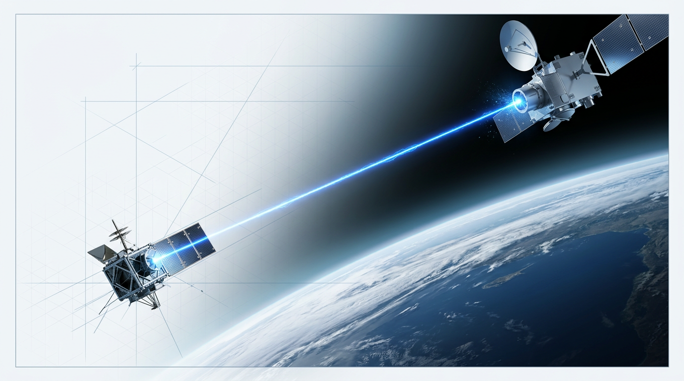
EDRS — the European Data Relay System, commercially branded SpaceDataHighway — is the clearest evidence that LEO-to-GEO optical relay has graduated from demonstration programme to operational infrastructure.
The system's two GEO nodes, EDRS-A and EDRS-C, each carry second-generation Laser Communication Terminals built by Tesat-Spacecom that achieve data rates of up to 1.8 Gbit/s across distances of up to 45,000 km — locking onto a target 135 mm in diameter, moving at 8 km/s relative to Earth, in under a minute.
EDRS has executed more than 75,000 optical relay links with LEO Earth observation satellites, delivering over 4.5 petabytes of data to European ground stations. This is not a technology demonstrator — it is a running commercial service with a documented operational tempo.
The mission architecture argument for LEO-to-GEO relay is as important as the data rate argument: a LEO satellite without a relay must wait up to 90 minutes for its next ground station overpass before it can downlink what it has collected.
EDRS eliminates that wait, enabling Copernicus Sentinel satellites to deliver data to users within minutes of acquisition — a capability that is operationally significant for disaster response, maritime surveillance, and any application where timeliness matters.
GEO Optical Feeder Links: The Appeal and the Bottleneck
The case for GEO optical feeder links starts with a genuine engineering constraint: Ka-band and even Q/V-band RF feeder links face hard spectrum limits that cap the aggregate throughput a very high throughput satellite (VHTS) can deliver to its ground segment.
An optical feeder link, operating in licence-free spectrum, can in principle deliver terabits per second on a single active link — removing the feeder bottleneck entirely and freeing the full RF spectrum for user links.
That appeal is genuine, and ESA, Airbus, and a range of commercial operators have invested seriously in studying it. But the gap between the engineering appeal and an operational system is where the honest analysis has to go.
The Availability Problem: What 99.9% Actually Requires
Commercial satellite operators require annual feeder link availability of 99.9% or better — a threshold that the same atmospheric constraints covering LEO direct-to-Earth links impose at GEO, with no contact-window reprieve.
The ESA ONUBLA study provides the most rigorous public quantification of what hitting that target demands from an optical ground station (OGS) network.
- OGS site count: Achieving 99.9% annual feeder link availability for a GEO satellite above Europe requires approximately 10 OGS sites across Europe — or as few as 5 if installations in Africa and the Middle East are permitted.
- Handover frequency: Even with a 10-site European network, the simulation shows roughly 1,300 handovers per year — approximately 10 per day on peak days — imposing significant operational complexity on the ground segment.
- Residual outage duration: Despite the diversity network, simulations show maximum no-link periods of up to 100 minutes in the best European-only scenario. Achieving 99.98% service availability requires up to 64 Tbit of on-board memory to bridge these gaps.
These figures reframe the feeder link question from a terminal engineering problem into a service architecture question: can the satellite system tolerate planned outage windows, and what is the true cost of the OGS network, its terrestrial fibre connections, and the handover management infrastructure?
The honest answer is that optical cannot simply replace the RF feeder link at GEO without a substantial, geographically distributed OGS investment that most operators have not yet committed to building.
Ka-Band RF Remains the GEO Reliability Backbone
EDRS itself is the clearest proof that hybrid is the rational GEO architecture: the system uses optical for the LEO-to-GEO inter-satellite link — where atmospheric constraints do not apply — and Ka-band RF for the GEO-to-ground trunkline, where they do.
This is not a design compromise forced by immaturity. It is the rational allocation of each technology to the link segment where its strengths dominate: optical wins in vacuum at high data rates; RF holds availability at the atmospheric interface.
For latency-sensitive traffic — commanding, telemetry, and real-time alerts — Ka-band RF remains the rational primary path at GEO regardless of what optical feeder link capacity is eventually deployed alongside it.
Looking further ahead, the planned EDRS-D node and Tesat's SCOT135 terminal point toward GEO-to-GEO optical crosslinks spanning up to 80,000 km — a capability Tesat and MPB Communications demonstrated at 100 Gbps in a laboratory environment in 2024. EDRS-D, intended for the Asia-Pacific region, would enable data to be backboned optically to European ground stations via GEO relay nodes, though its operational timeline remains unconfirmed from publicly available sources.
Step 4
Atmospheric Constraints and PAT: Engineering the Ground Interface

Key Insights
Cloud cover blocks optical links entirely.
PAT is solvable — at real cost.
Cloud cover is a link-blocking constraint, not merely a link-degrading one. When an optically thick cloud sits between a satellite and its ground station, the link is gone — not faded, not impaired, but absent. This is a categorical difference from RF, where rain fade degrades margin but rarely eliminates the link entirely.
JPL's infrared cloud imaging data from the Table Mountain Facility (TMF) in California puts numbers to this reality. Annual average cloud amount at TMF ran at 30.6% across the two-year measurement campaign, with February peaking above 51% — and during that winter peak, more than 60% of detected clouds carried optical attenuation exceeding 12 dB, sufficient to block a satellite optical link entirely.
The engineering significance is not that clouds exist — it is that the availability loss is predictable, site-dependent, and must be designed around. A single high-quality OGS, however well-sited, cannot deliver the annual availability that most operational feeder link or data-delivery architectures require.
Site Diversity: The Real Cost of High Availability
As covered in the GEO feeder link discussion, site diversity is the primary engineering answer to cloud cover. The ESA ONUBLA study quantifies what that answer costs: 99.9% annual feeder link availability at GEO requires 5–10 OGS sites distributed across Europe, reducing to as few as 5 if sites can be placed in Africa or the Middle East where cloud climatology is more favourable.
This is not a GEO-specific problem. The same ESA analysis shows that LEO direct-to-Earth systems targeting 98–99% data delivery need 8–12 geographically distributed OGS sites worldwide. Site diversity is a cross-cutting infrastructure requirement for any satellite optical communications architecture that crosses the Earth's atmosphere.
Operators evaluating optical ground segments should treat site diversity as a multi-site infrastructure programme with capital and operational implications — not a trivial add-on to a primary site. The number of sites required should be derived from the target availability figure and the cloud climatology of candidate regions, not assumed.
Turbulence, Scintillation, and Adaptive Optics
Even in clear air, the atmosphere is not benign. Refractive turbulence causes scintillation — intensity fluctuations at the receiver — as well as beam wander and reduced coupling efficiency into single-mode fibre receivers. These effects apply to both uplinks and downlinks, though through different mechanisms: on the downlink, a large ground aperture averages over turbulence cells; on the uplink, beam wander and spreading increase the power required to illuminate the satellite's acquisition detector.
Adaptive optics (AO) at the ground station is the primary engineering response. An AO system senses wavefront distortion caused by atmospheric turbulence and applies an inverse correction via a deformable mirror, allowing the signal to be focused closer to the diffraction limit of the telescope and improving coupling into single-mode fibre.
The practical gain from current AO systems is real but bounded. NASA research demonstrates performance improvements of approximately 1–6 dB depending on turbulence conditions and modulation order — with gains of 1–2 dB typical under lower background conditions, and up to 6 dB achievable in high-background cases with 1-metre-class AO systems. AO reduces the turbulence margin in the link budget; it does not eliminate it.
Current adaptive optics systems yield approximately 1–6 dB improvement over uncompensated receivers, depending on turbulence strength and modulation format. This is worth having in any demanding link budget — but it does not remove the need for turbulence margin. Operators should budget for residual atmospheric loss even with AO deployed.
The second major constraint — and the one that most directly shapes terminal cost — is pointing, acquisition and tracking precision. Optical beams are roughly 10,000 times narrower than RF beams: this is the source of their power efficiency and security properties, but it demands sub-microradian pointing accuracy between platforms moving at orbital velocities.
PAT Precision: What Demonstrated Missions Show
The engineering response to PAT at this precision level involves fine-pointing mechanisms, inertial sensing, vibration isolation, and payload-level feedback to the spacecraft bus. The question is not whether this is achievable — the mission heritage is clear that it is — but what it costs to achieve it.
| Mission | Link Type | Demonstrated PAT Performance | Key Engineering Investment |
|---|---|---|---|
| NASA TBIRD (6U CubeSat) | LEO-to-ground | ~5 µrad RMS closed-loop body pointing (single axis) | Custom optical assembly; payload-level feedback to spacecraft bus at 10 Hz; not a catalogue solution |
| EDRS / Tesat LCT | LEO-to-GEO (45,000 km) | Microradian-class acquisition and tracking across full link distance | Terminal mass 35 kg, power 120 W; purpose-built hardware with extensive heritage development |
Comparing the PAT performance and engineering investment from two key demonstrated missions gives operators a concrete basis for understanding what sub-microradian pointing actually requires in practice.
The TBIRD result is particularly instructive: 5 µrad RMS closed-loop body pointing from a 6U CubeSat was reached by closing a control loop between the TBIRD payload and the spacecraft bus at 10 Hz — with a custom optical assembly designed specifically to maintain transmit/receive boresight stability through environmental loading. It was not assembled from catalogue parts.
The EDRS/Tesat LCT heritage demonstrates that reliable acquisition and tracking across 45,000 km between moving platforms is operationally proven — but the terminal's mass and power envelope reflect the engineering investment required to get there. PAT is solvable; the cost of solving it should not be underestimated in procurement planning.
Uplink Beacon Power: Closing the Link Under Turbulence
Atmospheric turbulence spreads the uplink beam, increasing the transmitter power required to close the link and illuminate the satellite's acquisition detector. NASA research on uplink beacon propagation confirms that uncompensated beam divergence can range from 2 to 20 µrad depending on atmospheric seeing — and that correcting this to near-diffraction-limited performance requires adaptive optics on the transmit aperture.
Generic off-the-shelf optical components do not meet the power and stability demands of a satellite uplink beacon operating through real atmospheric conditions. The appropriate engineering response is high-power, application-engineered fibre amplification in the 1550 nm window, using a MOPA erbium-fibre architecture across the 1530–1625 nm band.
The 1550 nm window is the right choice for OGS uplink and beacon systems for several converging reasons: it delivers the output power needed to close demanding link budgets, it operates at an eye-safer wavelength than 1064 nm alternatives — directly relevant in ground station environments where personnel are present near high-power transmitters — and it benefits from the mature terrestrial fibre-telecom component ecosystem.
For this class of demanding OGS work, application-engineered amplifiers — built end-to-end to the specific link budget, operating band, power level, pulse regime, and integration envelope — outperform catalogue parts. Woodrow Scientific Limited's Custom EDFA is built on this principle: engineered across band, power, pulse regime, cooling, form factor and firmware to the application, not configured from a fixed catalogue.
- Power leadership at the leading commercially available levels: Pulse energies above 10 mJ, peak powers above 100 kW, and average powers above 100 W — pushing erbium-fibre output to the highest commercially available levels, which catalogue or off-the-shelf suppliers do not match in this power class.
- In-house design, build, qualification and support: WSL is a UK manufacturer rooted in Southampton's ORC — the birthplace of the EDFA — operating on patented technology with direct engineering support throughout integration. Many suppliers in the market are resellers or importers, with no in-house engineering depth and limited ability to support demanding or non-standard applications.
- Eye-safe 1550 nm with reduced-hazard-zone builds: Operating at 15xx nm carries a higher eye-damage threshold than 1064 nm sources. Reduced-hazard-zone builds are available, directly relevant to OGS environments where personnel may be working near high-power transmitters.
- Single-source C+L-band and flexible integration: Both C-band and L-band delivered through one cable from a single source, with air- or water-cooling options, CE and UKCA certification, and configurable form factor — covering the complete integration requirement from a single engineering engagement.
The practical implication for OGS programme managers: specifying a capable uplink beacon amplifier is not a commodity procurement decision. The power levels, operating stability, and integration requirements of a real satellite uplink beacon demand hardware that has been engineered to the application — not selected from a datasheet and hoped to perform.
Step 8
Spectrum, Security, and the Regulatory Dimension

Key Insights
No ITU filing — but not zero burden.
LPI is decisive for defence; incidental commercially.
Spectrum edge: greatest for new entrants.
Recognise first what the ITU Radio Regulations actually govern: electromagnetic waves below 3,000 GHz, a boundary confirmed explicitly in the Radio Regulations and in ITU-R Recommendation SM.2152. Optical communications — operating in the near-infrared at wavelengths around 1,550 nm, far above that ceiling — fall entirely outside this framework.
What that exemption removes from an operator's burden is substantial: no advance publication filing, no three-stage coordination process with adjacent administrations, no ITU cost-recovery fees (which for a coordinated satellite network notification can reach tens of thousands of Swiss francs), and no exposure to the first-come-first-served priority system that increasingly disadvantages new entrants in congested bands.
The pressure on Ka-band is not hypothetical — it is documented. More than 1,750 satellite networks have been notified in the Ka-band alone, and the ITU's own analysis describes coordination with hundreds of networks across dozens of administrations as the practical reality for any new operator entering that space. For a new constellation programme, the multi-year span from advance publication to recorded notification is a genuine schedule risk, not a bureaucratic inconvenience.
Against that backdrop, the optical spectrum advantage is real and operationally meaningful. But weigh it carefully: unregulated is not the same as unconstrained.
- Eye-safety compliance: High-power ground-station uplinks and beacon systems must comply with ANSI Z136.1 and Z136.6 standards, IEC 60825-12 (the specific standard for free-space optical communication systems), and FDA laser product performance regulations under 21 CFR Part 1040.
- FAA airspace coordination: Any ground transmitter propagating laser irradiance through navigable airspace must notify the FAA under Advisory Circular AC 70-1B, at least 30 days before operation, and receive a letter of non-objection. The FAA will most likely focus on ground station uplinks; spacecraft transmitters are generally exempt due to beam dispersion at altitude.
- DoD and NASA safety oversight: For government missions, the DoD Laser Clearinghouse screens outdoor laser use to protect orbiting spacecraft and sensors; NASA missions require review by the Laser Safety Review Board before launch. These are mission-specific obligations, not spectrum regulation, but they are real administrative steps.
The framing that matters here is that the regulatory burden is different in character, not absent. An optical operator trades ITU filing timelines and spectrum fees for eye-safety engineering, airspace notification, and safety board review — a different set of obligations, and generally a lighter one for a new entrant, but not zero.
For an established satellite operator with existing ITU filings and a coordination team already in place, the incremental cost of RF spectrum regulation is lower — they have already paid the entry cost. For a new constellation entrant, the multi-year ITU process represents a genuine schedule burden and material cost that optical links sidestep entirely. The advantage is most valuable to new entrants and least valuable to incumbents. Treat it as a calibration, not a blanket win.
Now turn to the security dimension, where the analytical picture is equally nuanced. The physical basis for low probability of intercept (LPI) in optical links is straightforward: the beam footprint is dramatically smaller than an equivalent RF beam at any given distance. NASA's optical communications programme illustrates this with a direct comparison — a 10 cm optical aperture at lunar distance illuminates a spot roughly 6 km across, while a Ka-band RF antenna illuminates a spot approximately 6,400 km across.
That geometric difference is a meaningful security property: an adversary attempting to intercept the link must be within the beam footprint, and at operational distances that footprint is a fraction of the area exposed by RF. The Aerospace Corporation's optical communications engineering team has noted that an RF beam can be 1,000 to 10,000 times broader than an optical beam — meaning interception of RF is geometrically far easier.
For government and defence payloads, where link security is a mission requirement, LPI is a primary driver of the optical choice. The Space Development Agency's investment in optically meshed LEO constellations, and DARPA's Blackjack programme goal of demonstrating a globally secure optical network for military communications, reflect this directly. The narrow beam geometry also underpins anti-jam resistance: without a broad beam footprint to target, a jammer must achieve the same pointing precision as the legitimate receiver — itself a significant technical barrier.
Distinguish this clearly from the commercial broadband context. Commercial operators are not typically designing against interception as a threat model. The Telesat Lightspeed whitepaper is instructive here: it explicitly frames LPI and low probability of detection as features of particular value to government customers such as Special Operations Command, while the optical inter-satellite links are presented primarily as a routing-resilience and high-capacity mesh architecture feature for the broader commercial offering. The security properties are real, but their operational relevance is mission-dependent.
Anti-jam resistance should also be stated accurately rather than absolutely. Optical links are more resistant to jamming than RF — the narrow beam geometry means there is no broadcast footprint to target with directed interference, and the pointing precision required to inject a jamming signal into the beam is itself a significant barrier. That is not the same as invulnerability, and programme architects should not treat it as such.
The overall picture from this dimension of the optical-vs-RF trade-off is one of genuine but context-dependent advantages: spectrum freedom is most valuable for new entrants navigating a congested RF coordination landscape; LPI and anti-jam properties are operationally decisive for government and defence missions, and largely incidental for commercial broadband constellations.
Step 9
Hybrid Optical-RF Architectures: The Pragmatic Near-Term Answer

Key Insights
Hybrid is the mature model, not a compromise.
LCRD and EDRS operate hybrid architectures at scale.
DTN makes optical intermittency manageable for non-real-time traffic.
The evidence assembled across the preceding sections points to a clear conclusion: optical and RF are not competing technologies vying for the same role, but complementary capabilities with structurally different strengths. Optical delivers the data volume that RF cannot match; RF delivers the availability and low-latency reliability that optical — constrained by cloud cover and atmospheric intermittency — cannot guarantee alone. Deploying both is not indecision. It is the correct engineering response to the current state of the technology.
This is not a transitional compromise to be discarded as optical matures. The atmospheric availability gap between optical and RF is structural: clouds are not going away, and the latency and availability advantages of RF links are permanent features of the physics, not temporary limitations of an immature technology. Hybrid is not a phase; it is the destination for most near-Earth mission architectures.
LCRD: The Operational Case for Hybrid Design
NASA's Laser Communications Relay Demonstration (LCRD) is the most instructive operational reference for hybrid architecture in the GEO relay context. LCRD includes a Ka-band RF trunkline alongside its optical links — not as a fallback for when the laser fails, but because an all-optical relay would suffer cloud-induced outages that block real-time commanding and telemetry.
Bulk science data can tolerate intermittency; commanding and telemetry cannot. The Ka-band link is sized precisely for the availability and latency requirement that optical cannot meet — a concrete illustration of the design principle that each link should be sized for what it does best, not for what the other cannot do.
LCRD also demonstrated frame-level switching between its optical and RF trunklines, routing latency-sensitive traffic such as commanding, telemetry, and science alerts over RF while directing bulk science file transfers over optical. This capability makes hybrid architectures operationally sophisticated rather than merely redundant: the system is intelligent about traffic routing, not simply switching between a primary and a backup pipe.
EDRS: Hybrid as Mature Commercial Service
EDRS — the European Data Relay System — provides the second major proof point, and a particularly significant one: it is not a demonstration but an operational commercial service. EDRS deploys optical inter-satellite links for bulk data relay between LEO observation satellites and its GEO relay nodes, while Ka-band RF handles the ground trunkline, providing the reliability backbone that an optical feeder link to ground cannot guarantee alone.
The EDRS architecture is therefore evidence of what the mature operational model looks like when a programme has moved beyond experimentation and committed to a hybrid design at commercial scale.
Size the optical link for the peak data volume requirement. Size the RF link for the availability and latency requirement. Do not attempt to satisfy both requirements with a single technology — the physics of each medium make this a permanent engineering truth, not a workaround for an immature technology.
Delay/Disruption Tolerant Networking (DTN) is the protocol-layer complement to this architectural principle. DTN store-and-forward protocols allow optical links to tolerate outages without data loss: data is buffered on-board and forwarded when the link is restored, providing Internet-like connectivity even through cloud interruptions. LCRD demonstrated DTN over optical links in operation, confirming that intermittency is operationally manageable for non-real-time traffic without requiring the link to be continuously available.
Ground Infrastructure and Standards for Hybrid Systems
The hybrid principle extends naturally to the ground segment. As established in the atmospheric constraints analysis, achieving 99.9%+ availability through optical-alone ground networks requires a large number of geographically distributed optical ground station sites. Supplementing a smaller OGS network with RF backup achieves equivalent system availability at substantially lower infrastructure cost — the ground-segment expression of the same design principle.
Scalability beyond individual programme implementations depends on interoperability standards, and that framework is now taking shape. CCSDS has published optical communications standards — including 141.0-B-1 and 142.0-B-1, with high-data-rate experimental specifications alongside them — while the Space Development Agency has adopted a 1550 nm optical communications terminal standard for its proliferated LEO transport layer. Together, these create the foundation on which multi-programme hybrid architectures can interoperate rather than remain isolated, single-vendor implementations.
Step 7
Deep Space: Where the Optical Advantage Is Most Decisive

Key Insights
Optical terminals: 55–65% of RF mass at Mars.
DSOC hit 8.33 Mbps at 2.68 AU — 16× RF.
RF stays essential: anomaly comms, navigation, cloud gaps.
Deep space is where the optical-versus-RF trade-off becomes most consequential — not because the physics change, but because the stakes do. At Mars distances and beyond, every kilogram of communications hardware competes directly with science payload mass, and every watt drawn by the communications subsystem is a watt unavailable to instruments.
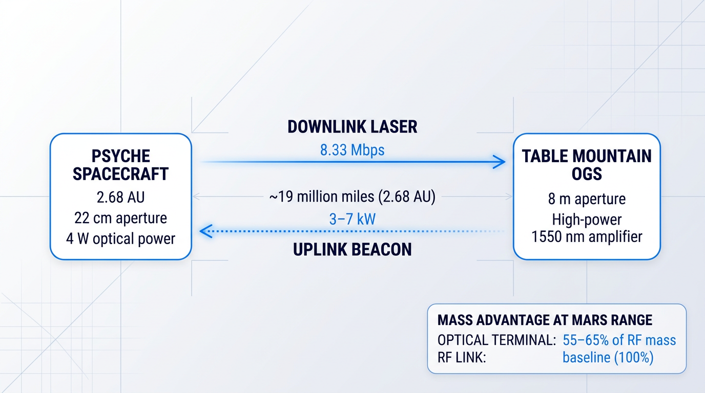
NASA comparative studies show optical flight terminals mass approximately 55–65% of equivalent RF subsystems at 2.7 AU, across daily data volumes from 0.1 to 10 Gb. At 1 Gbps and 2.67 AU, the RF communications subsystem mass ranges from 100–175 kg; the equivalent optical system weighs around 42 kg. That is not an incremental saving — it is mass that can be reallocated to science.
NASA's Deep Space Optical Communications (DSOC) demonstration aboard the Psyche spacecraft moved this advantage from theoretical to demonstrated. Launched in October 2023 and operating through September 2025, DSOC achieved a maximum downlink data rate of 267 Mbps — comparable to household broadband — when Psyche was approximately 19 million miles from Earth.
More significantly for mission planning, DSOC sustained a downlink rate of 8.33 Mbps at 2.68 AU — very close to the maximum Earth–Mars separation — using a 22 cm transmit aperture and just 4 W of average optical power. For context, the highest data rate ever achieved from a single 34 m DSN antenna at maximum Mars range using RF is approximately 500 kbps.
The deep-space uplink geometry introduces an atmospheric constraint that differs in character from the LEO-to-ground scenario. To point its downlink accurately back at Earth across interplanetary distances, the DSOC flight transceiver relies on a ground-transmitted uplink beacon as a pointing reference. Atmospheric turbulence spreads and distorts this beacon before it reaches the spacecraft, placing demanding requirements on ground transmitter power: the Table Mountain uplink station used for DSOC operates at 3–7 kilowatts of laser power to deliver sufficient irradiance at the flight terminal.
Generic off-the-shelf fibre amplifiers are not engineered for this regime; high-power, application-engineered amplification in the 1550 nm window — designed specifically for the link budget — is the credible technical approach for OGS uplink systems at these distances.
The ground infrastructure investment required to close the link at Mars distances is substantial and does not yet exist at scale. High-rate optical links from Mars maximum range require effective receive apertures in the 5–10 metre class. The near-term path is the DSN hybrid RF/optical antenna concept: a segmented 8 m optical aperture inside a 34 m DSN beam-waveguide antenna (DSS-23 at Goldstone), with two such antennas arrayed yielding an 11.3 m equivalent aperture, targeted for the early 2030s.
Even in the regime where optical is most advantageous, the hybrid architecture applies without exception. A spacecraft in anomaly cannot wait for an optical ground station to be available — and the pointing precision required for a deep-space optical link is incompatible with spacecraft fault-protection modes that constrain attitude.
- Emergency communications: Low-rate RF links remain the only viable path during spacecraft anomalies, fault protection, and attitude-constrained mission phases. Optical links require precise pointing that cannot be guaranteed when the spacecraft is not in nominal attitude control.
- Doppler navigation: RF Doppler tracking is the established method for precise orbit determination and navigation at deep-space distances. Optical ranging has been demonstrated at low rates, but RF remains the operational standard for navigation services.
- Coverage during OGS unavailability: Cloud cover blocks optical ground stations entirely. At a single site, cloud-free line-of-sight availability is typically 50–75%, meaning RF must carry continuity of contact during the remaining fraction, including periods near solar conjunction.
The mission-architecture calculus for data-intensive scientific missions is ultimately straightforward: optical's data rate advantage translates directly into science return. An MRO-class asset at Mars maximum range is limited to roughly 0.5 Mbps on RF; a future optical system with an 8 m ground aperture could sustain more than 100 Mbps on the same link.
For missions carrying high-resolution imaging instruments or wide-swath synthetic aperture radar — where data volumes per orbit can exceed what RF can downlink in a day — that difference determines how much of a planet gets mapped, and how often. The trade is real on both sides: the spacecraft-side mass and power advantage of optical is matched by the ground-segment investment required to realise it.
Conclusion
Requirements First: The Only Framework That Holds
The optical-versus-RF decision is not a question of which technology is winning — it is a question of what your mission actually requires.
Where atmospheric friction is absent and throughput-per-kilogram is the governing constraint, optical is the rational choice, and the industry has already acted on that logic at scale.
Where availability is non-negotiable and latency cannot be absorbed, RF remains the correct engineering answer — not a legacy position, but a deliberate one.
For most architectures in the contested middle ground, hybrid optical-RF is not a hedge: it is the design that honest requirements analysis produces.
Satellite Optical Communications: Frequently Asked Questions
The questions engineers, mission architects, and programme managers typically have after weighing the optical-vs-RF trade-off — answered directly.
In an optical ground station (OGS), an EDFA amplifies a low-power seed signal from a master oscillator to the output power needed to close the uplink through atmospheric turbulence and across the distance to the satellite. This MOPA (master oscillator power amplifier) architecture is the standard for OGS uplink and beacon systems. The 1530–1625 nm C- and L-band window is the natural fit: erbium-doped fibre is the gain medium of choice at this wavelength, it is eye-safer than 1064 nm, and it aligns with the SDA's standardisation at 1550 nm. Demanding link budgets are not well served by generic catalogue amplifiers. Woodrow Scientific Limited engineers its Custom EDFA end-to-end to the application — operating band, output power, pulse regime, cooling, form factor, and control firmware — achieving leading commercially-available power levels: average powers above 100 W, pulse energies above 10 mJ, and peak powers above 100 kW. Many suppliers in this space are resellers rather than manufacturers; WSL designs, builds, and qualifies everything in-house on patented technology developed from Southampton's ORC, the birthplace of the EDFA.
Partially — but only for thin, high-altitude clouds. Cirrus and similar thin high cloud allow partial transmission, and NASA's LCRD programme has demonstrated links through certain thin cloud conditions. Optically thick clouds — cumulus, stratus — block the link entirely, not merely degrade it. This is a categorical difference from RF, where rain fade is a matter of degree rather than a binary outage. The correct engineering response is not to attempt cloud penetration but to implement site diversity: multiple geographically distributed optical ground stations reduce the probability that all sites are simultaneously cloud-blocked. For well-sited networks with five or more stations across different climate zones, link availability can reach operationally acceptable levels. Cloud cover is a real constraint, but it is a solvable availability problem with a well-understood mitigation — not an intractable barrier to satellite optical communications.
PAT (pointing, acquisition and tracking) follows a three-phase sequence. First, the terminal sweeps a search pattern to locate the counterpart — the acquisition scan. Second, a coarse tracking loop locks onto the beacon signal. Third, a fast-steering mirror or equivalent actuator closes the fine pointing loop to sub-microradian precision. An additional correction is required for the point-ahead angle: at LEO-to-GEO distances, light travel time is non-negligible, so the transmit beam must lead the receiver's apparent position to compensate. The Tesat LCT terminals on ESA's EDRS have executed over 100,000 relay links between LEO and GEO, establishing strong heritage for this approach. NASA's TBIRD CubeSat demonstrated an alternative for LEO-to-ground links using spacecraft body-pointing, achieving 5 µrad RMS closed-loop performance. PAT is a solved engineering problem at operational scale — the hardware exists, the procedures are proven, and the cost is in terminal complexity rather than fundamental feasibility.
The industry has converged on the 1530–1625 nm window (C- and L-band, centred on 1550 nm) as the standard for satellite optical communications. Four factors drive this. First, eye safety: the retinal damage threshold is significantly higher at 1550 nm than at 1064 nm, which matters practically for ground-station operations and regulatory classification. Second, the mature terrestrial fibre-telecom ecosystem: transceivers, modulators, detectors, and amplifiers at this wavelength are commercially available at scale because the C-band is the backbone of global fibre networks. Third, EDFA availability: erbium-doped fibre amplification is well-developed across 1530–1625 nm, enabling high-power MOPA transmitter chains for OGS uplinks and beacons. Fourth, government standardisation: the US Space Development Agency has standardised 1550 nm as the interoperability wavelength for optical inter-satellite links across its Transport Layer constellation. Earlier systems used 1064 nm (Nd:YAG), but the field has moved decisively to 1550 nm.
Satellite optical communications is a subset of free-space optical (FSO) communications — not a synonym for it. FSO is the broader category covering any optical data link transmitted through free space (air or vacuum) rather than through a fibre. It includes terrestrial point-to-point links (building-to-building, last-mile connectivity), airborne links, and satellite links. The same underlying physics governs all FSO — laser propagation, beam divergence, atmospheric effects — but the engineering challenges differ substantially by application. Satellite links operate over hundreds to tens of thousands of kilometres, require sub-microradian pointing precision between moving platforms, and must manage atmospheric turbulence and cloud cover on any segment that passes through the atmosphere. Terrestrial FSO links operate over much shorter distances, typically metres to a few kilometres, with a different (though overlapping) set of atmospheric impairments. The term FSO is sometimes used loosely as a synonym for satellite optical links, but the distinction is precise and worth maintaining.
Yes — and several properties make it particularly well-suited to government and defence applications. The narrow optical beam illuminates a footprint of only a few kilometres at lunar distances, compared to thousands of kilometres for Ka-band RF. This geometric property makes interception significantly harder, delivering meaningful low probability of intercept and detection (LPI/LPD) for payloads where link security is a mission requirement. The same narrow beam makes directed jamming attacks substantially more difficult than against a broadcast RF signal. At programme scale, the US Space Development Agency's Transport Layer is the largest current government deployment of optical inter-satellite links, with 1550 nm standardised as the interoperability wavelength across the constellation. Hybrid RF/optical is the standard government architecture in practice: optical handles bulk data and high-throughput links, while RF covers commanding, telemetry, and availability-critical traffic where cloud outages cannot be tolerated. Optical is not a niche for government use — it is becoming the primary high-throughput layer.
It will not — at least not on any foreseeable timeline, and replacement is not the trajectory the industry is on. Hybrid architectures — optical primary, RF backup — are the long-term operational model. The reason is structural: RF penetrates clouds and rain with manageable, gradual degradation, making it inherently suited to always-available commanding, telemetry, and safety-critical links that optical cannot reliably guarantee through the atmosphere. Even the most mature operational optical relay systems, including ESA's EDRS and NASA's LCRD, include an RF channel precisely for this reason. The transition underway is more specific: optical is becoming the primary layer for high-throughput data links, while RF retains the backup and command roles. For in-space inter-satellite links, where the atmospheric problem disappears entirely, the case for optical-only is much stronger and adoption is already well advanced. The rational framing is complementarity, not competition — each technology serves the parts of the link budget it is physically best suited for.