


Introduction
Most people, if asked how the internet moves data, would guess radio signals or electrical pulses. The reality is quietly more astonishing: the vast majority travels as pulses of laser light, racing through glass fibres thinner than a human hair.
And it does not stop at the ocean floor. Laser-based communication spans an enormous range — from undersea cables and rooftop wireless links to satellites in orbit, and into emerging territory like Li-Fi and underwater optical systems.
Whether you are here out of curiosity or professional need, the physics is explained from first principles and the operational detail goes deep enough to be genuinely useful.
The guide moves from foundational concepts through each major deployment context, then into the practical challenges and the directions the field is heading.
TL;DR
Laser-based communication is not a niche technology waiting to mature — it already carries the world's data, from the cables beneath the oceans to the crosslinks between satellites in orbit.
Understanding how it works, where it excels, and where it faces real limits reveals just how central light has become to the way the modern world communicates.
This article covers:

How lasers encode and carry data
Fibre optic communications and wavelength multiplexing
RF vs laser communication: key differences
Free-space optical links and their challenges
Satellite and deep-space laser communications
Emerging applications: Li-Fi, underwater comms, QKD
What Are Lasers in Communications?
Every time you stream video, send an email, or load a webpage, the data almost certainly travels as pulses of laser light at some point in its journey. Lasers in communications refers specifically to the use of modulated laser light to encode and transmit data — either through a glass fibre waveguide or across open air and space. Modulation simply means varying a property of the light (its intensity, phase, or frequency) to represent the ones and zeros of digital information.
Why Laser Light — Not Just Any Light?
Ordinary light sources scatter energy in all directions across a broad mix of wavelengths. Laser light is fundamentally different, and four specific properties make it the right tool for carrying data over distance.
- Monochromaticity: Laser light occupies a single, precise wavelength, enabling wavelength-division multiplexing and predictable behaviour through optical components.
- Coherence: Photons travel in phase with one another, supporting advanced modulation techniques and the tight beam formation that long-distance links require.
- Collimation: The beam diverges very little over distance, concentrating power on the receiver rather than spreading it — unlike a torch beam or an LED.
- High brightness: High power per unit area per unit solid angle enables long-range links and strong signal-to-noise ratios even at the far end of a link.
Together, these four properties make laser light uniquely suited to carrying data across distances that would defeat any other light source — and at data rates that radio-frequency systems struggle to approach.
The Bandwidth Advantage Over Radio
The most consequential difference between laser communication and conventional radio lies in carrier frequency. Optical carrier frequencies sit around 10¹⁴ Hz — roughly 100,000 times higher than Ka-band radio frequencies near 32 GHz.
This matters because bandwidth in any communications system scales with carrier frequency: the higher the carrier, the more modulation bandwidth is available to pack in data. Think of it as a road — a wider road carries more lanes of traffic, and a higher carrier frequency is a far wider road.
The usable optical window around 1550 nm represents a swath of spectrum orders of magnitude larger than the entire radio-frequency spectrum humanity has ever allocated for communications — which is the foundational reason laser links can achieve data rates that RF systems cannot match.
This is not a marginal advantage. It is the reason that essentially all high-capacity, long-distance data transmission today relies on optical technology.
Two Modes: Guided Fibre and Free Space
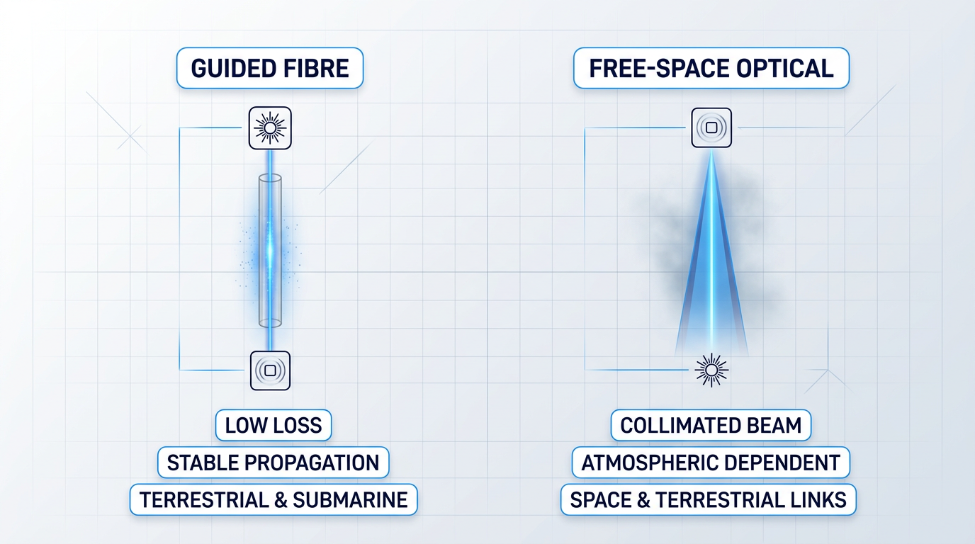
Laser-based communication splits into two broad deployment modes. In fibre optic systems, laser light is guided through a thin glass waveguide with very low signal loss, forming the backbone of terrestrial and submarine networks. In free-space optical (FSO) systems, the beam travels through open air, vacuum, or water with no physical medium to guide it — used in everything from building-to-building links to satellite crosslinks in orbit.
Both modes exploit the same laser properties; the difference lies in the propagation environment and the engineering challenges that follow. Later sections of this guide cover each in depth.
A Note on Terminology
The field uses several terms interchangeably depending on context. Optical communications is the most common label in fibre network contexts; lasercom and FSO (free-space optical) appear frequently in space and terrestrial free-space contexts. You will also see the terms used together or interchangeably across technical literature — all refer to the same underlying technology of transmitting data with laser light.
The Main Laser Types: A Brief Orientation
Three device families dominate the field. Semiconductor diode lasers are the workhorses: compact, efficient, and found in everything from short data centre interconnects to transcontinental fibre spans. Fibre lasers deliver higher output power and are used in demanding free-space uplink applications.
A third device type worth knowing — though not a transmitter laser in the strict sense — is the erbium-doped fibre amplifier (EDFA). EDFAs are all-optical amplifiers that boost a signal without converting it back to electronics, and their invention made long-haul fibre networks commercially viable. The term will appear throughout this guide; the concept is straightforward once named.
With the foundational properties and concepts established, the next question is how they are actually put to work — the mechanics of encoding data onto a laser beam and the physics of a complete optical communications link.
How Lasers Carry Data: Modulation and Wavelength
A laser beam on its own carries no information — it is simply a steady carrier of light. The engineering challenge is turning that carrier into a data stream, and the answer lies in optical modulation: deliberately varying one of the beam's properties — its intensity, phase, or frequency — in a pattern that a receiver can decode.
Think of it as the optical equivalent of Morse code. Just as a telegraph operator switches a signal on and off to encode letters, an optical transmitter switches or shifts the laser to encode binary data.
The simplest and most widely deployed scheme is on-off keying (OOK), the special case of intensity modulation where the laser is switched on to represent a '1' and off to represent a '0'. The receiver is a photodiode that converts detected optical power directly into electrical current — no phase reference required. This approach, formally called intensity modulation with direct detection (IM/DD), dominates short- and medium-reach fibre links because it is inexpensive, tolerant of receiver noise, and straightforward to implement.
High-capacity systems demand more than one bit per symbol. Differential phase-shift keying (DPSK) encodes data in the phase difference between successive symbols rather than in raw intensity, improving receiver sensitivity. Quadrature amplitude modulation (QAM) goes further, varying both phase and amplitude simultaneously to pack multiple bits into each symbol. In dense wavelength-division multiplexed (DWDM) systems carrying 80 or more channels on a single fibre, this spectral efficiency gain is not academic — it is the difference between filling a fibre and leaving capacity on the table.
How modulation is applied to the laser is a separate engineering decision. In direct modulation, the laser's drive current is varied directly to change its output power — simple and low cost, but with a significant drawback.
That drawback is frequency chirp: when a semiconductor laser's drive current changes, the carrier density in its active region shifts, which in turn changes the refractive index and causes the emission wavelength to drift slightly with each bit transition. Chirp broadens the signal spectrum, and when that broadened spectrum interacts with fibre dispersion, pulses spread and limit how far the signal can travel without error. Research on directly modulated lasers shows this effect typically confines them to distances of around 10 km or less at 10 Gbps on standard fibre.
For long-haul links, the solution is external modulation: the laser runs at constant power and a separate device — most commonly a Mach-Zehnder modulator (MZM) — imposes the data pattern by splitting the optical path into two arms and recombining them with a controlled phase difference, producing intensity modulation through interference. The MZM introduces little or no chirp and supports the high bandwidths needed for DWDM transmission, at the cost of added component complexity and expense.
Laser Types Used in Optical Communications
Semiconductor diode lasers are the workhorses of optical communications, spanning a range of types suited to different reach and capacity requirements. Fibre lasers and erbium-doped fibre amplifiers play specialised but essential roles at the higher-performance end of the ecosystem.
| Laser Type | Typical Wavelength | Key Characteristic | Primary Use Case |
|---|---|---|---|
| Fabry-Perot (FP) diode | 1300 nm or 1550 nm | Multi-longitudinal-mode output; broad linewidth; low cost | Short-reach links up to a few km; access networks |
| Distributed feedback (DFB) | 1310 nm or 1550 nm | Single longitudinal mode via Bragg grating; narrow linewidth; side-mode suppression >30 dB | Long-haul DWDM; metro networks; 5G fronthaul beyond 15 km |
| VCSEL | 850 nm (primarily) | Surface-emitting; low threshold current; array-fabrication friendly | Short-reach data centre links on multimode fibre |
| Fibre laser | 1030–1120 nm (Yb); ~1550 nm (Er) | Near-diffraction-limited beam quality; high power scalability; narrow linewidth options | FSO uplinks; sensing; specialised communications |
| Erbium-doped fibre amplifier (EDFA) | 1530–1565 nm (C-band) | All-optical amplification; high gain (20–40+ dB); no electrical conversion | Transoceanic fibre spans; DWDM booster and pre-amplifier stages |
Comparison of the five principal laser types used in optical communications by wavelength, key characteristic, and primary deployment context
The pattern across these types reflects a clear engineering logic: as link distance and channel density increase, the laser requirements tighten. VCSELs win on cost and ease of array integration for the tens-of-metres links inside data centres, where multimode fibre relaxes alignment tolerances. DFB lasers take over for anything beyond a few kilometres — their narrow linewidth is essential for DWDM channel spacing and for coherent modulation formats that rely on a stable carrier frequency. Fabry-Perot lasers occupy the low-cost short-reach tier where their broader spectral output is not yet a problem. Fibre lasers and erbium-doped fibre amplifiers (EDFAs) sit at the top of the power and performance hierarchy, enabling the transoceanic spans and high-power free-space uplinks that other sources cannot reach.
Which brings the question to wavelength: why do almost all long-haul and free-space optical systems converge on 1550 nm?
The first reason is fibre loss. Silica glass attenuation is governed by two competing mechanisms: Rayleigh scattering, which decreases with increasing wavelength (scaling as the inverse fourth power of wavelength), and infrared absorption from Si-O bond vibrations, which rises steeply beyond about 1600 nm. The crossover between these two effects creates a loss minimum in the 1550 nm region, where standard single-mode fibre achieves roughly 0.2 dB/km — a figure confirmed across multiple independent sources and now being pushed below 0.15 dB/km in ultra-low-loss variants.
The second reason is amplification. The erbium ion (Er³⁺) has an energy transition near 1530 nm, which means EDFAs provide gain across the C-band (1530–1565 nm) — precisely the wavelength range where fibre loss is lowest. This alignment was not guaranteed by physics; it is a fortunate coincidence that the telecommunications industry has built its entire long-haul infrastructure around. As IEEE Spectrum noted of the EDFA's inventor Robert Mears, the amplifier enabled optical signals to cover transcontinental distances without needing conversion back to electrical form, transforming what was possible in long-distance communications.
The third reason is eye safety. Wavelengths above approximately 1400 nm are absorbed by the cornea and lens before reaching the retina — meaning 1550 nm energy cannot focus on the retina the way shorter-wavelength light can. As IEEE Spectrum's analysis of lidar safety rules notes, laser safety standards allow significantly higher output power at 1550 nm than at wavelengths such as 905 nm that transmit through to the retina. For free-space optical systems operating in environments where human exposure is possible, this raised maximum permissible exposure threshold is a meaningful operational advantage.
No single factor explains 1550 nm's dominance — it is the only wavelength where minimum fibre loss, EDFA gain bandwidth, and a raised eye-safety threshold all coincide. Remove any one of those three, and the engineering calculus for long-haul and FSO systems looks very different.
One further concept is worth planting before moving into specific deployment contexts: photons per bit. Receiver sensitivity in optical communications is often expressed as the minimum number of photons that must arrive per bit for the receiver to achieve a target error rate. For terrestrial fibre links with high received power, this is rarely the binding constraint. For deep-space links — where the signal has crossed millions of kilometres and the received power is vanishingly small — photons per bit becomes the central design driver. That application is explored in a later section; the concept is introduced here because it frames what optical receivers are fundamentally doing: counting the quantum events that carry information.
With the mechanics of modulation, the principal laser types, and the rationale for 1550 nm established, the natural next step is the deployment context where these technologies have had the deepest and most consequential impact: the optical fibre networks that carry the world's internet traffic.
Fibre Optic Communications: Lasers Inside the Cable
Right now, as you read this, the data reaching your screen has almost certainly travelled as pulses of laser light through glass fibres thinner than a human hair. Optical fibre carries the vast majority of the world's internet traffic — undersea cables, intercontinental backbones, and metropolitan networks are all built on the same fundamental principle: light guided through glass over extraordinary distances with remarkably little loss.
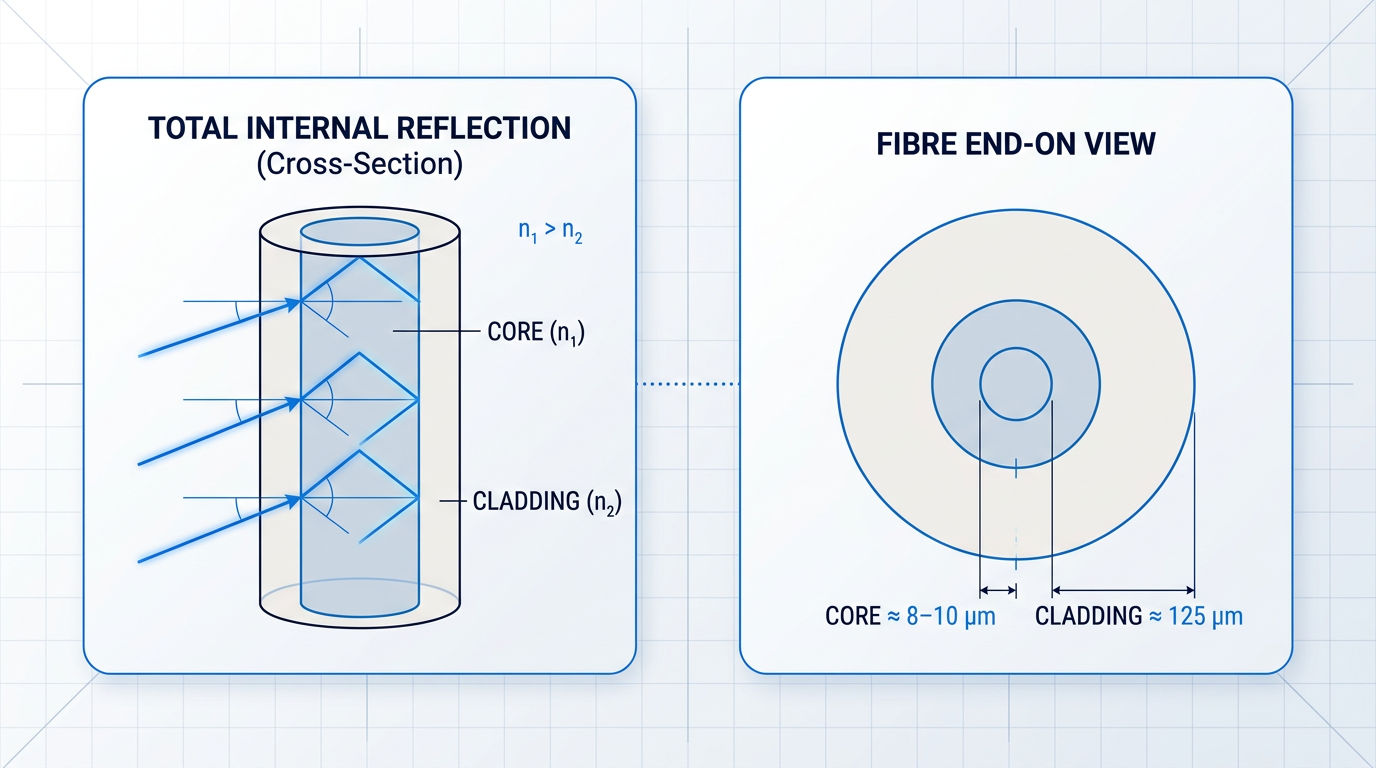
The governing physics is total internal reflection. An optical fibre consists of a glass core surrounded by a cladding layer with a slightly lower refractive index. When light travelling through the denser core strikes the core-cladding boundary at a shallow angle — beyond the so-called critical angle — it is completely reflected back into the core rather than escaping into the cladding.
This reflection repeats continuously along the length of the fibre, confining the light and allowing it to propagate with very low loss over distances that would be impossible in free air or copper wire. The fibre acts, in effect, as a waveguide: channelling light along a defined path with a precision that no other transmission medium matches at optical frequencies.
Single-mode and multimode fibre
Not all optical fibres are alike. The core diameter determines how many distinct propagation paths — called modes — the fibre supports, and this has profound consequences for transmission distance and data rate.
| Fibre type | Typical core diameter | Propagation modes | Typical reach | Primary application |
|---|---|---|---|---|
| Single-mode (SMF) | 8–10 µm | One | Hundreds of kilometres | Long-haul, transoceanic, metro backbone |
| Multimode (OM3/OM4) | 50 µm | Many | Up to ~300–550 m at 10 Gbps | Data centre interconnects, building links |
Comparison of single-mode and multimode fibre on core diameter, propagation modes, reach, and application — using figures consistent with established technical literature (MIT OCW, Wikipedia Optical fiber).
Single-mode fibre (SMF) has a core of just 8–10 µm — roughly one-tenth the width of a human hair — which is narrow enough to permit only a single propagation mode. This eliminates modal dispersion: the phenomenon where multiple modes travel at slightly different velocities, causing light pulses to spread in time and ultimately limiting how far and how fast data can be sent.
Multimode fibre has a larger core (typically 50 µm) that supports many propagation modes simultaneously. The inevitable velocity differences between those modes cause pulse spreading that becomes prohibitive beyond a few hundred metres at high data rates. Multimode fibre is therefore the right choice for short-reach links inside data centres and buildings, where its lower cost and easier alignment are genuine advantages — but SMF is the only practical option for long-haul and transoceanic networks.
Attenuation and the 1550 nm loss minimum
Even in exceptionally pure glass, light loses power as it propagates — a property called attenuation, measured in decibels per kilometre (dB/km). The loss is strongly wavelength-dependent, shaped by two competing physical mechanisms.
At shorter wavelengths, Rayleigh scattering dominates: random density fluctuations in the glass at near-atomic scales scatter light out of the fibre core. Rayleigh scattering scales as the inverse fourth power of wavelength (λ⁻⁴), so it falls steeply as wavelength increases. At longer wavelengths, infrared absorption by the silica lattice's inter-atomic bonds takes over and drives loss back upward.
The minimum of this loss curve falls near 1,550 nm, where standard single-mode fibre achieves approximately 0.2 dB/km — a benchmark figure consistent with established fibre physics literature. This is the primary engineering reason why 1,550 nm became the standard wavelength for long-haul fibre communications, as introduced in the previous section: the fibre loss physics points unambiguously to this window.
Alongside attenuation, chromatic dispersion is the other key constraint on long-haul performance. Different wavelength components within a pulse travel at slightly different speeds in the fibre, causing the pulse to spread in time and ultimately limiting achievable data rates. The narrow-linewidth DFB lasers discussed earlier minimise this by emitting at a very precise wavelength. Where dispersion is still a limiting factor, engineers use dispersion-shifted fibre — designed to move the zero-dispersion point to 1,550 nm — or dispersion-compensating fibre modules that actively reverse accumulated dispersion along a link.
Wavelength-division multiplexing: one fibre, many channels
Solving attenuation and dispersion opens the door to transmission over long distances — but it says nothing about capacity. The technology that transformed fibre from a point-to-point link into a high-capacity network backbone is wavelength-division multiplexing (WDM): sending multiple laser wavelengths, each carrying an independent data stream, down a single fibre strand simultaneously.
At the transmit end, a multiplexer combines signals from multiple laser sources — each tuned to a distinct wavelength — onto one fibre. At the receive end, a demultiplexer separates them back out. Each wavelength channel is entirely independent: it carries its own data at its own modulation rate, and the aggregate capacity of the fibre is the sum of all channels.
Dense WDM (DWDM) takes this further by packing channels tightly across the C-band. A typical DWDM system uses 80 channels at 50 GHz spacing, and systems with 160 channels at 50 GHz spacing are also deployed — all on a single fibre pair. According to Corning, a single optical fibre link can carry more than 150 terabits of data per second, enough to support 30 million simultaneous HD video streams.
Before EDFAs, one electronic repeater was required per wavelength channel — meaning a 80-channel DWDM system needed 80 separate repeaters at every amplification point. A single EDFA replaces all of them, amplifying every channel simultaneously in the optical domain. This is what made transoceanic DWDM economically and technically viable.
The EDFA: the amplifier that made global fibre viable
DWDM's capacity multiplication only becomes useful over long distances if the signal can be amplified without degrading. Before the invention of the erbium-doped fiber amplifier (EDFA), amplification required optical-electrical-optical (OEO) conversion: the optical signal was decoded into electronic bits, amplified electrically, and re-encoded as light. This process was slow, expensive, and — critically — wavelength-specific: one repeater per wavelength channel, every few tens of kilometres.
The EDFA eliminated that bottleneck by providing all-optical gain. The core of a silica fibre is doped with trivalent erbium ions (Er³⁺); a pump laser operating at 980 nm or 1,480 nm excites those ions to a higher energy state. When signal photons pass through, they stimulate the excited erbium ions to emit additional photons at the signal wavelength — amplifying the light directly in the optical domain, without any electrical conversion.
Crucially, the EDFA's gain bandwidth spans the entire C-band simultaneously. This means a single amplifier can boost all 80 or more DWDM channels at once, regardless of their individual wavelengths or modulation formats. As noted by the Wikipedia article on optical communications repeaters, one broadband optical amplifier replaces what would otherwise require many tens of wavelength-specific electronic repeaters per fibre.
The EDFA was first described by Robert Mears in a 1985 paper in Electronics Letters, with a key low-noise demonstration published in 1987 — authored by R.J. Mears, L. Reekie, I.M. Jauncey, and D.N. Payne. The work was carried out at the Optoelectronics Research Centre (ORC) at the University of Southampton. According to the IEEE Spectrum account of the invention, prior to the EDFA, transatlantic cables operated at 140 Mbps and required submarine electronic repeaters every few tens of kilometres; the EDFA enabled signals to remain optical across intercontinental distances of thousands of kilometres and increased bandwidth by more than three orders of magnitude.
The optical spectrum used in fibre communications is divided into named bands. The C-band (approximately 1,525–1,565 nm) is the dominant window for long-haul DWDM: it coincides with both the fibre loss minimum and the EDFA's gain bandwidth — an alignment that made C-band the natural engineering choice. The L-band (approximately 1,565–1,610 nm) extends capacity further using longer erbium-doped fibre sections to shift the gain to longer wavelengths, and is deployed where C-band capacity alone is insufficient. The S-band (approximately 1,450–1,490 nm) exists as a further extension, supported by thulium-doped amplifiers, though it sees less common deployment.
Together, these technologies define the infrastructure underlying the modern internet. A single fibre pair, carrying 80 or more DWDM channels each at 100 Gbps or beyond, with EDFAs spaced periodically along the route, delivers aggregate capacities in the tens of terabits per second — all through a glass strand thinner than a strand of hair, running across ocean floors and continental backbones alike.
With the guided-fibre case established in full, the natural next question is how optical links compare to radio-frequency alternatives — a comparison that sheds light on why optical is increasingly the preferred path wherever bandwidth and spectral capacity are the binding constraints.
What is the difference between RF and laser communication?
The instinct is to frame this as a simple speed contest — lasers are faster, so lasers win. The reality is a set of genuine engineering trade-offs where each technology has structural advantages the other cannot replicate, and where the choice between them depends on operating conditions as much as raw performance.
The bandwidth advantage of optical is rooted in carrier frequency. As established in NASA NTRS analysis (20070017310), at Ka-band frequencies of 32 GHz, usable bandwidth is typically around 500 MHz; for optical systems at 1550 nm, that bandwidth may be 1,000 times larger — enough to carry substantially more data without resorting to power-hungry, mass-inefficient modulation schemes.
A NASA/JPL-affiliated analysis confirms the frequency ratio directly: the Ka-band deep-space downlink sits at 32 GHz, while the 1550 nm optical carrier corresponds to approximately 193.5 THz — a ratio of roughly 6,000 to one, which represents the theoretical headroom advantage optical holds over RF for signal-to-noise ratio and data throughput.
| Axis | RF (Ka-band reference) | Laser / Optical (1550 nm reference) |
|---|---|---|
| Carrier frequency | ~32 GHz (Ka-band deep-space downlink) | ~193.5 THz (1550 nm); optical frequencies ~10¹⁴ Hz — roughly 6,000× higher than Ka-band |
| Usable bandwidth | ~500 MHz at Ka-band (NASA NTRS 20070017310) | Up to ~1,000× greater than Ka-band; no hard ceiling imposed by spectrum allocation |
| Spectrum licensing | Regulated by ITU, FCC, NTIA; allocations are finite and contested | Currently unregulated; no licence required for optical communications links (NASA NTRS 20170001405) |
| Beam geometry | 75 cm antenna produces ~6,400 km spot from lunar distance (NASA NTRS 20240012165) | 10 cm aperture produces ~6 km spot from the same distance — beam stays tight, concentrating power on target |
| Terminal mass (SWaP) | Baseline reference | Optical flight terminal ~60% of the mass of the equivalent RF subsystem (NASA NTRS 20040191349); one mission comparison: 30.7 kg optical vs 61 kg RF (NASA NTRS 20180007086) |
| Weather resilience | Penetrates cloud cover and fog without significant signal loss | Blocked entirely by dense cloud and fog; clear-sky or guided-medium path required |
| Pointing requirement | Broad beam; coarse pointing adequate | Sub-microradian accuracy required; narrow beam demands precise alignment |
Head-to-head comparison of RF and laser/optical communications across six key engineering axes, using sourced figures from NASA NTRS documents.
The table reveals a consistent pattern: optical wins on bandwidth, spectrum freedom, beam efficiency, and terminal mass; RF wins decisively on all-weather availability; and pointing precision is the direct engineering cost of optical's narrow beam.
The beam geometry difference also carries a security implication that is structural rather than incidental: because an optical beam illuminates a footprint orders of magnitude smaller than a comparable RF transmission, the geographic area from which the link can be intercepted or jammed shrinks correspondingly, giving optical links inherently lower probability of detection and interception (NASA NTRS 20240016424).
The SWaP advantage matters most for satellite payloads, where every kilogram of terminal mass competes directly with instruments, fuel, and structure. NASA NTRS 20170001405 notes that an optical solution can achieve approximately 50% savings in mass and 65% savings in power compared to conventional RF systems at equivalent data rates — figures that translate directly into launch cost and mission capability.
The critical limitation to state plainly: clouds and dense fog block optical links entirely, while RF penetrates cloud cover without significant degradation. The mechanism is physical — fog aerosols are comparable in size to the 1550 nm wavelength, producing severe Mie scattering that attenuates the beam. Rain and snow have lower impact because their droplets are large relative to the wavelength, but thick cloud remains an absolute barrier.
This atmospheric vulnerability is what drives hybrid RF/optical architectures: operators who require high link availability use optical for peak throughput under clear-sky conditions and maintain an RF backup channel for periods when cloud cover would otherwise sever the link entirely.
The same physics that concentrates optical power into a tight, efficient beam also demands sub-microradian pointing precision — an engineering challenge with no equivalent in RF systems, where broad beams are forgiving of angular errors. This pointing requirement becomes the dominant systems engineering problem for satellite optical terminals, a topic developed fully in the satellite communications section of this guide.
RF and optical are not rival technologies vying for the same role. RF provides resilient, all-weather connectivity; optical delivers high throughput where clear-sky conditions or guided media are available. The practical result is that the most capable communication architectures use both, with RF as the availability backbone and optical as the high-rate payload channel.
The next section examines free-space optical (FSO) communications in depth — how atmospheric impairments are quantified and mitigated, what site-diversity strategies operators deploy to maintain availability, and where FSO links are being deployed today across terrestrial and ground-to-space paths.
Free-Space Optical Communications: Laser Links Through the Air
Fibre gives a laser beam a waveguide to travel through — a protected glass channel that isolates it from the environment. Free-space optical (FSO) communication removes that protection entirely, sending the beam across open air between a transmitter and receiver that must hold an unobstructed line of sight. The atmosphere becomes both the medium and the adversary.
FSO sits between guided fibre and satellite links as a distinct deployment mode: longer reach than a cable run through a building, shorter and more weather-exposed than a link to orbit, and governed by a set of impairments that neither of those other contexts faces in quite the same way.
Where FSO Is Used Today
The most common terrestrial FSO deployments are last-mile broadband access where trenching fibre is impractical or uneconomical, and building-to-building enterprise links across streets or campuses where a licensed fibre route would take months to provision.
Mobile network backhaul is a growing application, particularly as 5G densification creates demand for high-capacity connections between small cells and the core network at locations where physical cabling is constrained.
FSO also serves temporary high-capacity requirements: disaster recovery operations, military and tactical communications, and broadcast events where a fibre run is not feasible in the available time. The capability envelope is substantial — current systems deliver tens of gigabits per second over ranges up to several kilometres under good atmospheric conditions.
Atmospheric Impairments: What Actually Happens
Understanding atmospheric impairments is not academic taxonomy — each mechanism has a direct consequence for link availability and system design, and they do not all respond to the same mitigations.
- Absorption: Atmospheric gases, principally water vapour, absorb optical energy. At 1550 nm, the wavelength sits within a transmission window that minimises this loss — wavelength choice is inseparable from absorption management.
- Rayleigh scattering: Sub-wavelength particles scatter light with intensity scaling as λ⁻⁴. At 1550 nm this is modest, but in clear air it is the baseline scattering floor operators must account for.
- Mie scattering: Particles comparable in size to the wavelength — fog droplets, haze, aerosols — scatter much more efficiently and with far less wavelength dependence. This is the dominant impairment in degraded visibility.
- Atmospheric turbulence: Thermal gradients produce refractive-index fluctuations causing beam wander, scintillation, and wavefront distortion — the dominant impairment in clear-air conditions.
Of these, scintillation — rapid intensity fluctuations at the receiver driven by refractive-index turbulence — is the impairment that most directly degrades bit-error performance in clear weather, while beam wander (movement of the beam centroid) can cause the beam to miss the receive aperture entirely at longer ranges.
Geometric loss from beam divergence adds a fourth budget item: even a tightly collimated beam spreads with distance, and at kilometre-scale ranges this spreading contributes measurably to the received power deficit.
Fog aerosols are comparable in size to the 1550 nm wavelength, making them highly effective Mie scatterers. Attenuation in dense fog can exceed 350 dB/km — effectively opaque. Rain and snow droplets are far larger than the wavelength, making them much weaker scatterers; their impact on FSO link availability is significantly lower than fog, which is the opposite of the intuition most engineers carry from RF experience.
Mitigation Strategies That Actually Work
No single mitigation eliminates all atmospheric impairments — operational FSO deployments combine several approaches to achieve the availability targets their applications require.
- Site diversity: Spatially separated ground stations ensure localised fog or cloud rarely blocks all sites simultaneously. This is the primary availability strategy for ground-to-satellite optical uplinks.
- Emitter diversity: Multiple spatially separated transmit apertures reduce scintillation impact through spatial diversity, smoothing the intensity fluctuations seen at the receiver.
- Aperture averaging: Larger receive apertures integrate intensity across the beam cross-section, averaging out scintillation-induced fluctuations that a small aperture would experience in full.
- Adaptive optics: Wavefront sensing and correction compensates for turbulence-induced distortion in real time — particularly valuable for uplink pre-compensation at satellite ground stations.
- Hybrid RF/FSO architectures: A lower-rate RF backup link maintains connectivity when the optical path is weather-blocked. This is a complementary architecture, not a concession — it preserves service continuity without replacing optical capacity.
Site diversity and hybrid RF/FSO are the two mitigations with the broadest operational adoption, because they address availability at the system architecture level rather than requiring the optical link itself to fight the weather.
Ground-Station Uplink Amplification
Closing the link budget for a ground-to-satellite optical uplink is a demanding engineering problem. The amplifier must overcome atmospheric attenuation, geometric spreading over the uplink path, and pointing losses — all while delivering sufficient power at the satellite aperture to support the intended data rate.
High-power EDFAs at 1550 nm are the enabling technology for this role. But the amplifier's job is not simply to produce watts: it must handle the combined beacon and data functions, remain compatible with evolving standards (SDA, CCSDS, and operator-proprietary protocols), and integrate cleanly into the ground station's optical and control architecture.
Our EDFA for free-space optical communications, developed by Woodrow Scientific Limited, is built specifically for this context. Its lead capability is something that distinguishes it from the rest of the market: the tracking beacon and uplink data are nested in a single amplified beam, with amplitude modulation carrying the beacon tone at low modulation depth and the data signal above it.
This single-beam approach eliminates the need for a separate beacon channel, simplifying the optical train at the ground station and reducing the number of components that must be precisely co-aligned and maintained.
The amplifier is configured end-to-end to the client's ground station — not supplied from catalogue. At the hardware layer, this covers band selection (C-band, L-band, or dual-band from a single source), output power (10 W standard, higher on request), 2- and 4-emitter array configurations with multi-station synchronisation for site and emitter diversity deployments, an external optical input to amplify third-party transmitters at OOK up to 20 Mbps, ±2 nm wavelength tunability, and air or water cooling.
At the software layer, WSL's Modulation-on-Demand provides software-selectable amplitude modulation throughout the link: square or sinusoidal waveforms, adjustable frequency and modulation index, combined beacon and data modulation via TTL, and switchability between CCSDS and SDA standards at high power across C/L-band. An integrated-seed uplink supports up to 10 Mbps OOK.
This depth of configurability across both the physical build and the control layer is a product of WSL designing and manufacturing the amplifier in-house, on patented technology, with engineering lineage rooted in Southampton's Optoelectronics Research Centre — the institution where the EDFA was originally developed.
Many suppliers in the high-power EDFA market are resellers or importers rather than manufacturers. That distinction matters in practice: it determines whether the supplier can customise at depth, provide direct engineering support when integration problems arise, or adapt the product as the standards landscape changes. WSL designs, builds, qualifies, and supports its amplifiers entirely in-house. The unit carries CE and UKCA certification.

Regulatory and Operational Realities of FSO Deployment
The technical challenges of FSO are well documented. The regulatory and operational constraints of actually deploying a high-power uplink laser are discussed far less often — and they are non-trivial.
High-power 1550 nm uplink lasers are Class 4 devices under IEC 60825-1. The 1550 nm wavelength does carry a higher permissible exposure limit than 1064 nm — the cornea and lens absorb wavelengths above 1400 nm, which raises the threshold for retinal damage — but Class 4 designation still applies, and laser safety procedures, appropriate eyewear, and controlled access to the beam path are non-negotiable requirements.
A high-power laser beam directed skyward is a hazard to aircraft. Operators must coordinate with aviation authorities and implement airspace deconfliction protocols before transmitting — this is a genuine operational overhead, not a formality.
Satellite illumination authorisation is a further requirement: uplink activities must be registered with relevant space commands to avoid inadvertently illuminating satellites not party to the link, which carries both safety and diplomatic implications.
Ground station siting is also constrained in ways that are easy to underestimate. Effective sites need clear-sky access and low atmospheric turbulence — typically elevated or coastal locations — alongside fibre backhaul connectivity to carry the traffic the optical link delivers.
The Standards Landscape: A Moving Target
An operator deploying a ground station today faces a standards environment that has not yet converged. The SDA OCT Standard (US Space Development Agency Optical Communications Terminal Standard), the CCSDS optical physical layer and coding standards, and ESA's ESTOL specification coexist without full harmonisation — and each constellation operator may layer proprietary protocols on top.
Hardware choices made now will need to remain compatible as those standards evolve, or the operator faces partial or full replacement of ground-station equipment. That makes software-definable operation across standards a genuine engineering requirement for any serious deployment — not a feature on a specification sheet.
The same optical physics that governs a terrestrial FSO link applies when the receiver is in orbit — but at satellite distances, the pointing challenge becomes the dominant engineering constraint, and the ground station infrastructure discussed here becomes the foundation for everything that follows.
EDFA Technology Built for Free-Space Optical Links
Woodrow Scientific develops EDFAs purpose-built for FSOC applications, delivering on-demand modulation at high average output powers. Explore our free-space optical communications capability.

Satellite Laser Communications: Links, Crosslinks and Standards
Something significant is happening in low Earth orbit right now: laser crosslinks are moving from proof-of-concept demonstrations into operational constellation infrastructure at scale, reshaping how satellite networks are architected and how data moves around the planet.
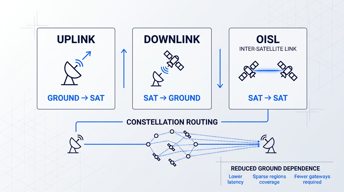
Satellite laser communications involve three distinct link configurations: the uplink (ground terminal transmitting to a satellite), the downlink (satellite transmitting to a ground terminal), and inter-satellite crosslinks — laser links between satellites, also known as OISLs (Optical Inter-Satellite Links).
At satellite distances, the advantages of optical over RF that were outlined earlier in this guide become more acute, not less. Optical terminals offer far greater bandwidth per unit of size, weight, and power (SWaP), and they operate entirely outside the congested, licensed RF spectrum — a genuine bottleneck for high-throughput satellite missions that optical links bypass entirely.
Pointing, Acquisition, and Tracking (PAT)
The central engineering challenge of satellite optical communications is not bandwidth or power — it is PAT: pointing, acquisition, and tracking. Optical beams at satellite distances are only a few microradians wide, and the required pointing accuracy is a small fraction of that beamwidth — on the order of a microradian or less, according to the JPL Descanso monograph on laser communications systems.
To put that in context: a 1-metre RF antenna operating at Ka-band requires pointing accuracy of a few milliradians; the optical equivalent demands accuracy that is orders of magnitude more stringent, well beyond what spacecraft attitude-control systems can achieve unaided.
Spacecraft jitter, thermal flexure, and atmospheric turbulence (for ground-to-satellite links) all work against this precision — the platform disturbances can be many beamwidths in magnitude and occur at frequencies of a hundred hertz or more, requiring a dedicated pointing-control subsystem as an integral part of every optical terminal design.
Establishing a link begins with the acquisition phase: a staged scan-and-detect process in which each terminal systematically searches the uncertainty region for the other terminal's signal before a link can be locked. This is not instantaneous — the NASA ILLUMA-T/LCRD cooperative PAT process, for example, involves each terminal transmitting a wide beacon signal while the other scans and pulls in on it, progressively narrowing the uncertainty.
Once acquired, the system transitions to closed-loop tracking: a lower-power beacon signal from the remote terminal is detected by a tracking sensor, which generates an error signal proportional to the angular deviation from the target line of sight, feeding a fine-steering mirror loop that continuously corrects the beam direction as the relative geometry evolves.
A pointing error of just one microradian at satellite distances is enough to break the link. RF systems tolerate pointing errors of 0.1 to 0.5 degrees — several orders of magnitude more forgiving. PAT is not a peripheral engineering concern; it is the central design driver of every satellite optical terminal.
Inter-Satellite Crosslinks (OISLs)
OISLs propagate entirely through vacuum, which eliminates the atmospheric turbulence, absorption, and scattering that dominate ground-to-satellite links. The propagation physics are clean — but high relative velocities between satellites in different orbital planes introduce their own pointing challenge, since the link geometry changes continuously and rapidly as the spacecraft move.
Architecturally, OISLs are transformative: a satellite carrying data can relay it across the constellation to the nearest ground station rather than waiting for its own pass over a gateway, reducing end-to-end latency, cutting dependence on dense ground-station networks, and enabling coverage over regions — polar areas, open oceans — where ground infrastructure is sparse or absent.
Real-World Deployments
Several programmes have moved satellite laser crosslinks from laboratory demonstrations into operational or near-operational service, anchoring this technology firmly in the present rather than the future.
- SpaceX Starlink polar crosslinks: Polar Starlink satellites launched from January 2021 carried laser inter-satellite links, enabling high-latitude coverage without ground stations over the poles. SpaceX subsequently extended crosslinks across the full constellation.
- SDA Tranche 0 cross-vendor demonstration: A York Space satellite using a Tesat terminal successfully exchanged data with a SpaceX-built satellite — the first confirmed cross-vendor optical link in the US military's Proliferated Warfighter Space Architecture.
- Telesat Lightspeed OISL mesh: Each Telesat Lightspeed satellite carries four 10 Gbps OISLs, forming a global Layer 2 mesh network in space with onboard routing between any two points on Earth.
- ESA Sentinel-1A / Alphasat link: By July 2015, the Sentinel-1A and Alphasat terminals had completed 100 optical inter-satellite links, with acquisition achieved in as little as 19 seconds and stable 1.8 Gbps transmission across up to 45,000 km.
Taken together, these deployments confirm that OISLs are no longer experimental — they are being fielded at constellation scale by both commercial operators and government programmes, with cross-vendor interoperability now demonstrated in orbit.
Interoperability and Standards Fragmentation
The proliferation of optical terminals has exposed a structural problem: constellations built around different optical terminal standards cannot communicate with each other, creating siloed networks that limit the utility of the technology for any mission requiring cross-constellation connectivity.
Three distinct standards frameworks currently coexist without full harmonisation: the SDA OCT Standard (the US Space Development Agency's Optical Communications Terminal standard, now at version 3.2, defining the interoperability specifications for the Proliferated Warfighter Space Architecture); the CCSDS optical physical layer and coding standards from the Consultative Committee for Space Data Systems; and a range of proprietary protocols used by commercial constellation operators.
Active programmes are working to bridge the gaps. DARPA's Space-BACN (Space-Based Adaptive Communications Node) programme is explicitly targeting this problem, pursuing a reconfigurable, multi-protocol optical terminal capable of adapting to most current OISL standards — in DARPA's own framing, the goal is to "eliminate stovepipes and connect space." Phase 1 of Space-BACN selected 11 teams including major constellation operators and terminal developers.
For ground station operators, the fragmented landscape is not an abstract standards debate — it is a concrete engineering requirement. Hardware that can switch between standards without physical replacement is necessary for any operator serving multiple constellation customers, and the SDA's insistence on OCT Standard compliance across its vendor base is widely credited with accelerating terminal development and commercial adoption more broadly.
Standards fragmentation remains an active, unsolved challenge. The SDA OCT Standard and Space-BACN are responses to a real and current difficulty, not retrospective tidying of a problem already resolved.
Satellite laser communications have demonstrated that optical links are viable and scalable at orbital distances — from LEO crosslinks spanning thousands of kilometres to GEO relay links exceeding 40,000 km. The next section pushes these same principles to their logical extreme: deep-space optical communications, where the distances stretch to lunar and interplanetary ranges and the engineering challenges become qualitatively more severe.
Deep-Space Optical Communications: Laser Links Across Millions of Miles
Everything covered so far in this guide — fibre attenuation, atmospheric turbulence, the pointing demands of satellite crosslinks — operates in a regime where received optical power is at least measurable in conventional terms. Deep space changes the problem entirely: the inverse-square law means that at lunar distances of roughly 400,000 km, and far more so at interplanetary ranges, the received signal is not merely weak but reduced to a trickle of individual photons arriving at the detector.
This is the photon-starved regime, and it demands a fundamental rethink of both modulation strategy and receiver technology.
On the modulation side, pulse position modulation (PPM) is the format of choice for deep-space links precisely because of its energy efficiency. Rather than encoding data in the phase or amplitude of a continuous carrier, PPM concentrates all optical energy into narrow pulses whose position within a fixed time slot encodes the data symbol — maximising the peak power seen by the detector while minimising average energy per bit. This contrasts with DPSK, which as discussed in the modulation section suits high-rate near-Earth links where received power is comparatively plentiful.
On the receiver side, the enabling technology is the superconducting nanowire single-photon detector (SNSPD): a nanowire structure cooled to cryogenic temperatures that can register the arrival of a single photon with exceptional timing resolution and detection efficiency, far exceeding what conventional semiconductor photodetectors achieve at single-photon sensitivity levels.
SNSPDs were used in the ground terminals of NASA's first lunar optical demonstration, providing the sensitivity needed to close a link across 400,000 km on a received signal that amounts to counting individual photons rather than processing a conventional optical signal.
NASA's Deep-Space Optical Demonstrations
Four NASA missions have progressively pushed the frontier of demonstrated optical communications capability, from the first lunar-range link through to a sustained interplanetary data relay across hundreds of millions of miles.
| Mission | Year Active | Distance / Orbit | Peak Downlink Rate | Key Milestone |
|---|---|---|---|---|
| LLCD (Lunar Laser Communications Demonstration) | 2013 | Lunar orbit (~400,000 km) | 622 Mbps | First optical link at lunar range; space terminal used half the mass and 25% less power than comparable RF system |
| LCRD (Laser Communications Relay Demonstration) | 2021–present | GEO (geostationary orbit) | 1.244 Gbps (return); 155 Mbps (forward) | First two-way GEO optical relay; extended to LEO via ILLUMA-T on ISS (first light Dec 2023) |
| TBIRD (TeraByte Infrared Delivery) | 2022–2024 | LEO (530 km sun-synchronous) | 200 Gbps | Highest downlink rate from any space platform; 4.8 TB transferred error-free in a single 5-minute pass |
| DSOC (Deep Space Optical Communications) | 2023–2025 | Deep space (aboard Psyche spacecraft) | 267 Mbps (at ~19M miles) | First optical link from true deep space; distance record of 307 million miles (Dec 2024); 13.6 Tb total data received |
Comparison of NASA optical communications demonstration missions by distance, data rate, and milestone achieved.
Reading across these four missions reveals a field that has advanced along two distinct axes simultaneously: data rate and link distance. TBIRD's 200 Gbps figure reflects the proximity of LEO — with a short path and commercial fibre telecom transceivers adapted for the space environment, burst rates that were previously inconceivable from a spacecraft become achievable. DSOC's achievement is categorically different: 267 Mbps from 19 million miles is not impressive because of the raw rate, but because the link closes at all at that distance, with data rates that fall predictably with the inverse square of range as Psyche travelled deeper into the solar system.
The LLCD result, achieved in 2013, also deserves framing against the RF baseline it replaced: 622 Mbps from lunar orbit, compared with 100 Mbps from the Lunar Reconnaissance Orbiter's Ka-band radio system — while the optical space terminal weighed 30.7 kg versus 61 kg for its RF counterpart, and drew 90 W against 120 W.
LCRD's significance lies less in its raw data rate and more in what it represents architecturally: the transition from a one-off demonstration to a persistent relay infrastructure. When ILLUMA-T on the International Space Station achieved first laser link with LCRD on 5 December 2023 — relaying data at 1.2 Gbps from LEO through GEO to optical ground stations in California and Hawaii — it completed NASA's first two-way, end-to-end laser relay chain.
TBIRD's most striking result is not the 200 Gbps peak rate but what that rate enables within a short LEO pass: in a single 5-minute window on 17 May 2023, the system downlinked 4.8 TB of data error-free, using commercial off-the-shelf fibre telecom transceivers validated for the space environment — demonstrating that the maturation of terrestrial fibre technology is directly transferable to space optical communications.
DSOC, flying aboard the Psyche spacecraft launched in October 2023, set its distance record on 3 December 2024 by downlinking data from 307 million miles away — farther than the average distance between Earth and Mars — before concluding its 65th and final pass on 2 September 2025, having delivered 13.6 terabits of data in total.
The Pointing Challenge at Interplanetary Distances
As discussed in the satellite crosslinks section, optical beams are measured in microradians and pointing precision is a fundamental constraint on any free-space optical link. At deep-space distances, that constraint becomes qualitatively more severe: the required pointing accuracy drops to a fraction of a microradian, while spacecraft jitter from reaction wheels, thrusters, and structural vibration is orders of magnitude larger than the allowable pointing error.
This demands dedicated jitter isolation subsystems — mechanical and electronic architectures that decouple the optical terminal from the spacecraft body well enough to hold the beam on a target millions of miles away despite the vibration environment of a functioning spacecraft.
Deep space introduces a pointing challenge with no equivalent at satellite distances: the point-ahead angle correction. At interplanetary ranges, light travel time is measured in minutes to tens of minutes — meaning a spacecraft transmitting back to Earth cannot aim at Earth's current position but must aim at where Earth will be when the photons arrive, accounting for both Earth's orbital motion and the spacecraft's own velocity during the transit time.
This is not a small correction: at the distances DSOC operated, the point-ahead angle represents a genuinely significant offset that must be computed and applied in real time, adding a layer of navigational precision to what is already an extreme pointing problem.
DSOC downlinked data from 307 million miles on 3 December 2024 — farther than the average Earth-Mars distance — while still closing the link at a meaningful data rate. The data-rate reduction across that distance followed the inverse-square law precisely, confirming that deep-space optical link budgets behave as the physics predicts, even at ranges no optical communications system had previously operated.
The same underlying physics that enables a photon to carry data reliably across 307 million miles is now being applied at the opposite extreme of the distance scale: in indoor wireless networks, underwater optical links, and quantum-secured channels — each presenting its own distinct engineering challenges, and each representing a frontier of lasers in communications that the next section examines.
Li-Fi, Underwater Optical Comms, and Quantum Key Distribution
The preceding sections traced laser communications from the glass fibres beneath city streets to a spacecraft 307 million miles from Earth. But the field is also expanding in a different direction — into environments and applications that have nothing to do with distance records: the interior of a hospital ward, the floor of the ocean, and the quantum-physical layer of cryptographic security. Three domains in particular are advancing rapidly enough to deserve substantive treatment: Li-Fi indoor optical networking, underwater optical wireless communication (UOWC), and quantum key distribution (QKD) over optical links.
Li-Fi: Optical Wireless Networking for Indoor Environments
Li-Fi (Light Fidelity) uses modulated light — from LEDs or laser diodes — to carry data wirelessly indoors, replacing radio waves with optical signals that travel between ceiling-mounted luminaires and user devices.
The technology reached a significant maturity milestone with the ratification of IEEE 802.11bb-2023, the first dedicated Li-Fi standard, published as an amendment to the 802.11 wireless LAN suite. It specifies operation in the 800–1000 nm near-infrared band, with a maximum MAC-layer throughput of 9.6 Gbps — and by adopting the 802.11 MAC framework, it enables seamless handoff between Li-Fi and conventional Wi-Fi access points within the same network.
The choice of laser diodes over LEDs as the optical source is where performance diverges sharply. Lasers can be modulated at roughly ten times the rate of LEDs, and because laser-based Li-Fi generates white light by mixing outputs from multiple laser diodes at different wavelengths, each wavelength can serve as a separate data channel — the same wavelength division multiplexing principle that underpins long-haul fibre networks. The result: while LED-based Li-Fi reaches data rates around 10 Gbps, laser-based implementations can exceed 100 Gbps.
What makes Li-Fi deployable across a room rather than just point-to-point is the attocell architecture: each luminaire creates a small optical cell covering a radius of a few metres, and as a user moves through a space, their device hands off between adjacent attocells — analogous to cellular handoff, but at room scale.
The near-term deployment model is hybrid Wi-Fi/Li-Fi, with Li-Fi handling high-density, high-throughput cells and Wi-Fi providing coverage continuity — including in areas where light coverage is interrupted. Li-Fi is not positioned to displace Wi-Fi; it complements it.
Li-Fi carries genuine advantages in contexts where radio frequency communications are problematic. In electromagnetically sensitive environments — hospitals, aircraft cabins, industrial facilities with RF-sensitive equipment — light-based networking introduces no RF interference. Physical security is also inherent: optical signals do not penetrate walls, so a Li-Fi link cannot be intercepted from outside the room. And unlike the congested, licensed RF spectrum, the optical band is unregulated and offers vastly more available spectrum for data transmission.
Underwater Optical Wireless Communication
Underwater communication has long faced a fundamental physical constraint: radio waves are absorbed almost immediately by seawater. At 2.4 GHz — the frequency used by Wi-Fi and Bluetooth — attenuation in seawater reaches approximately 1,695 dB/m, rendering conventional RF links useless beyond a few centimetres. Acoustic links fill the gap for long-range underwater communication, but they are limited to kilobits-per-second bandwidths and suffer from latency on the order of seconds per kilometre of propagation — a serious bottleneck for modern underwater operations.
Optical links offer a fundamentally different solution. Seawater has a blue-green transmission window centred on approximately 450–550 nm where optical absorption is at its lowest — a property identified in oceanographic research as far back as the 1960s. This wavelength regime is a sharp departure from the 1,550 nm that dominates fibre and free-space optical links; the physics of seawater, not silica glass, dictates the operating wavelength. Within this window, UOWC systems can achieve Gbps data rates over distances of hundreds of metres in clear ocean water.
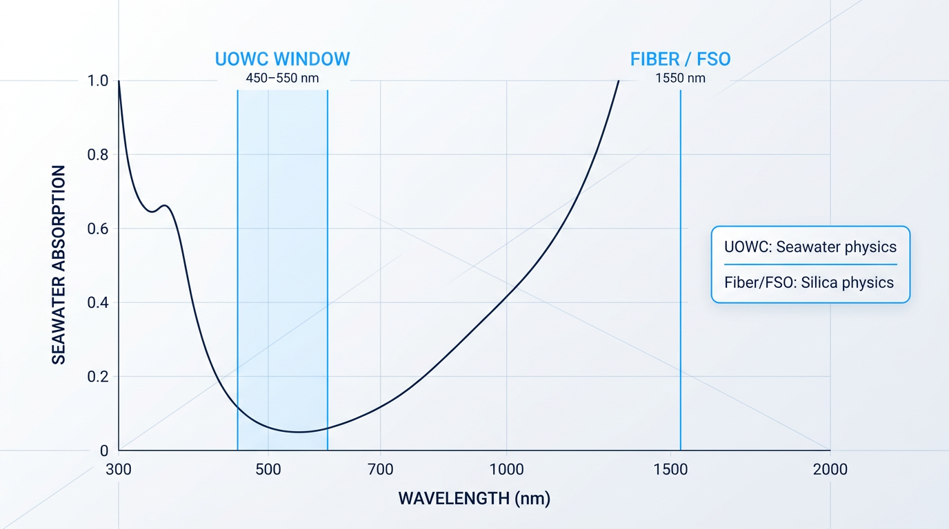
Achieving those data rates in practice requires overcoming a set of challenges that are structurally similar to those in free-space optical (FSO) links — but driven by water physics rather than atmospheric physics.
- Absorption and scattering: Both vary significantly with water type. Clear open-ocean water is far more transparent than coastal or harbour water, which contains suspended particles and dissolved organic matter.
- Oceanic turbulence: Temperature gradients and salinity variations cause refractive-index fluctuations that scatter and distort the optical beam, analogous to atmospheric turbulence in FSO links.
- Beam alignment: The narrow optical beam demands precise pointing between transmitter and receiver. Any misalignment — from platform motion or current — can break the link entirely.
- Range limitations: Practical link distances run from roughly 100 m in turbid coastal or harbour water to around 500 m in clear open-ocean conditions. Turbulence and scattering constrain the upper end.
Taken together, these constraints mean that UOWC operates best in short-range, controlled geometries — a very different regime from the kilometre-scale FSO links the reader has already encountered, but one that is entirely appropriate for the applications it targets.
Those applications are genuinely compelling: autonomous underwater vehicle (AUV) communication, where high-bandwidth optical links allow survey vehicles to offload large datasets to a surface node rapidly; ocean monitoring and scientific data collection; military underwater networks connecting submarines and unmanned underwater vehicles; and offshore energy infrastructure, where optical links can serve subsea equipment on oil and gas platforms and offshore wind farms.
UOWC remains an emerging technology — laboratory and field demonstrations have confirmed its core performance claims, but mature commercial deployments at scale do not yet exist. The research community continues to address the channel-modelling challenges, particularly for turbid and thermally stratified water columns.
Quantum Key Distribution over Optical Links
Quantum key distribution (QKD) is a method of sharing cryptographic keys using the quantum-mechanical properties of individual photons, such that any eavesdropping attempt unavoidably disturbs the quantum states being transmitted — and is therefore detectable by the communicating parties before any secret information is compromised.
The security guarantee is information-theoretic: it derives from the laws of physics rather than from the assumed computational difficulty of a mathematical problem. This distinguishes QKD categorically from conventional public-key cryptography, whose security can in principle be broken by a sufficiently powerful quantum computer.
QKD is an optical technology that runs on the same physical infrastructure — fibre networks and free-space links — that the rest of this guide has described. The critical difference is that it operates at the single-photon level, encoding key bits in the quantum states of individual photons rather than in the intensity or phase of a multi-photon carrier beam. That single distinction has a profound practical consequence: quantum signals cannot be amplified.
In classical optical communications, signal loss over distance is managed with optical amplifiers. Amplification is not available to QKD: copying or amplifying a quantum state necessarily destroys it, a consequence of the no-cloning theorem of quantum mechanics. Fibre-based QKD is therefore limited to point-to-point links of roughly 100–200 km before photon loss overwhelms the secure key rate — a hard constraint that has no equivalent in any other form of optical communications.
Free-space links offer a path around this constraint. Because the vacuum of space introduces negligible photon loss compared to fibre, satellite-based QKD can extend secure key distribution to intercontinental distances. China's Micius satellite demonstrated this concretely in 2017, achieving satellite-to-ground QKD over distances of up to 1,200 km — a key rate reported in Nature as approximately 20 orders of magnitude greater than would be achievable through an optical fibre of the same length.
Unlike every other form of optical communication, QKD signals cannot be amplified — amplification would destroy the quantum state carrying the key. This makes repeaterless range the fundamental limit for fibre-based QKD, capping practical links at roughly 100–200 km without quantum repeaters, which remain an active area of research.
QKD is the most forward-looking of the three domains in this section. It is not yet a mass-deployed technology, but investment and standardisation activity are accelerating, driven by the anticipated arrival of quantum computers capable of breaking current public-key cryptographic schemes. The optical communications infrastructure already described in this guide — fibre networks, FSO links, and satellite optical terminals — forms the physical substrate on which future quantum-secure networks will be built.
With these emerging applications extending lasers in communications into indoor environments, the ocean floor, and the quantum-physical layer of security, the field's near-term trajectory points toward even greater scale and integration — which the next section examines directly.
The Future of Laser Communications
The demonstrations are done. The physics is proven. What is happening now — and over the next decade — is the transition from proof-of-concept to operational infrastructure, at a scale that will make the past two decades of laser communications experiments look like a prelude.
LEO Constellations: From Demonstration to Infrastructure
The single largest deployment of laser communications technology in history is already underway in low Earth orbit, driven not by government agencies but by commercial constellation operators.
- SpaceX Starlink: Laser inter-satellite links are now standard on all Starlink satellites, enabling routing across the constellation without ground station hops.
- Amazon Project Kuiper: Prototype satellites KuiperSat-1 and -2 demonstrated 100 Gbps optical inter-satellite links across ~1,000 km, with production satellites entering service.
- Telesat Lightspeed: Each of the 198-satellite constellation's spacecraft carries four 10 Gbps optical inter-satellite links, forming a global mesh network in space.
- SDA Proliferated Warfighter Space Architecture: Tranche 0 delivered 28 optically-connected satellites; Tranche 1 adds 154 operational space vehicles, all equipped with optical communications terminals.
Telesat Lightspeed's launch campaign is scheduled to begin in mid-2026, with global services targeted for late 2027, using 14 Falcon 9 launches carrying up to 18 satellites each.
NASA has also tapped Starlink's laser crosslink technology directly: for Artemis III, two SpaceX Starlink mini laser terminals are being installed on the exterior of the Orion spacecraft to downlink 4K imagery to Mission Control — a signal of how deeply commercial optical comms infrastructure has matured.
The Push Toward Terabit-Class Space Links
The data rate ambitions for space optical communications are climbing steeply, and the trajectory is grounded in demonstrated results rather than projections.
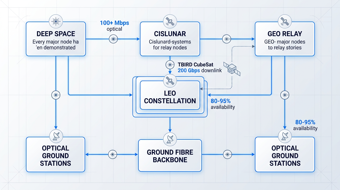
NASA's TBIRD CubeSat — a 3U payload on a 6U spacecraft — demonstrated 200 Gbps downlinks from LEO and achieved error-free transfer of more than 1 terabyte in a single 5-minute pass, the highest downlink rate achieved by any space platform at the time of its operation.
Building on that foundation, NASA's next-generation 100 Gbps optical relay programme targets space-to-ground links and optical crosslinks between relay nodes exceeding 100 Gbps, with user services up to 10 Gbps — aggregating traffic from LEO, MEO, GEO, and cislunar distances.
The hardware frontier enabling these rates is amplifier power: development programmes are currently targeting 100 W optical amplifiers for spaceborne use and 1,000 W amplifiers for ground stations, with the explicit goal of facilitating terabit-per-second data transmission from space to Earth.
Ground Infrastructure: The Layer That Must Keep Up
As space segment ambitions scale, the optical ground station network has emerged as a critical architectural layer in its own right — no longer an afterthought to the space terminal.
Site diversity is becoming standard practice rather than an optional mitigation: analysis shows that a single continental US site achieves cloud-free line-of-sight availability of 60–70%, while a coordinated network of three geographically separated sites can push that figure to 80–95%.
ESA's active ground infrastructure programmes — including ALASCA, OFELIAS, ORELIA, and TOmCAT — are developing adaptive optics uplink pre-compensation systems capable of correcting atmospheric wavefront distortion in real time, targeting 24/7 operability for optical feeder links.
The practical implication is clear: system-level link availability depends as much on ground infrastructure investment as on the space terminal's performance, and the field is now treating them as co-equal design challenges.
Interoperability: The Defining Engineering Challenge
As optical inter-satellite links proliferate across dozens of constellations, the field is confronting a problem that no single programme can solve unilaterally: standards fragmentation.
The current landscape includes the SDA OCT Standard (now at version 3.2.0, specifying up to 2.5 Gbps bi-directional links with backward compatibility across tranches), CCSDS protocols used in NASA missions, ESA's own standards work, and the proprietary optical link implementations inside commercial constellations like Starlink.
DARPA's Space-BACN programme (Space-Based Adaptive Communications Node) addresses this directly: its goal is a reconfigurable, multi-protocol optical terminal that can adapt on-orbit to communicate across different OISL standards, effectively creating an internet of LEO satellites spanning government and commercial constellations.
Phase 1 selected 11 teams — including SpaceX, Telesat, Amazon Kuiper Government Solutions, and Viasat — to develop the terminal architecture and the command-and-control schema for cross-constellation connectivity, with a target of 100 Gbps on a single wavelength at under $100,000 per terminal.
Every major component of a global optical network — crosslinks, relays, ground stations, deep-space links — has been individually demonstrated. Whether those components can be connected across competing constellation architectures and standards is the question that determines whether the long-term vision is achievable.
Industry voices have noted the scale of the challenge plainly: satellite communications systems follow divergent protocols, and achieving seamless integration across vertically integrated constellations will require either a dominant anchor customer demanding compliance or a standards body with sufficient authority to compel it.
Deep Space: From Demonstration to Crewed Missions
The deep-space optical communications roadmap has its own near-term milestone that moves the technology decisively beyond robotic demonstrations: NASA's O2O (Optical to Orion) system, flying on the Artemis II crewed lunar mission, will be the first optical communications link on a crewed mission.
O2O provides a downlink of up to 260 Mbps from the lunar vicinity — compared to a maximum of around 6 Mbps on S-band RF — enabling 4K video streaming from the Moon and allowing Orion to downlink roughly six times more data per day at its nominal 80 Mbps operating rate.
Looking further out, future Mars missions are credible candidates for optical links: NASA analysis indicates that optical communications from Mars could deliver return data rates greater than 100 Mbps, compared to the approximately 500 kbps maximum achievable with today's RF systems at maximum Mars range using a 34-metre DSN antenna.
That comparison — 100+ Mbps optical versus ~500 kbps RF from Mars — illustrates why optical communications are considered essential for the science return ambitions of future deep-space missions, not merely preferable.
Terrestrial FSO and Li-Fi: The Ground-Level Trajectory
The forward trajectory of laser communications is not confined to space: on the ground, both free-space optical links and Li-Fi are reaching performance milestones that reframe their roles in next-generation networks.
Recent field demonstrations have pushed urban FSO throughput into multi-terabit territory: researchers have demonstrated 5.7 Tbps over a 4.6 km link in Eindhoven using coherent wavelength-division multiplexing, while a separate field trial achieved 4 Tbps over 1.8 km — figures that place FSO firmly in the same capacity class as high-end fibre for point-to-point urban links.
For Li-Fi, the IEEE 802.11bb standard, ratified in 2023, provides the global framework for interoperable light-based wireless devices operating at up to 9.6 Gbps — built on the 802.11 Wi-Fi MAC layer to enable transparent handoff between Li-Fi and Wi-Fi access points.
Laser-based Li-Fi research points toward the next performance tier: using wavelength-division multiplexing across ten parallel laser channels, laboratory demonstrations have achieved aggregate data rates exceeding 100 Gbps indoors — a tenfold improvement over LED-based systems and a plausible target for dense indoor network deployments in 6G-era infrastructure.
The Integrated Optical Network: A Credible Trajectory
The long-term destination implied by all of the above is an integrated space-ground optical network: LEO constellations connected by laser crosslinks, relayed through GEO nodes, extended into cislunar space and eventually toward deep-space missions, with terrestrial fibre as the ground backbone and optical ground station networks as the interface layer.
What makes this a credible engineering trajectory rather than a conceptual aspiration is that every major node has been individually demonstrated: DSOC proved deep-space optical links at interplanetary distances; TBIRD demonstrated 200 Gbps burst delivery from a CubeSat; LCRD proved GEO relay operations; Starlink crosslinks proved operational OISL deployment at constellation scale.
The remaining work is integration — connecting those nodes across constellation boundaries, standardising the protocols that allow them to interoperate, and building the ground infrastructure that can sustain high link availability at the system level.
Taken together, the demonstrations, the active constellation deployments, the emerging standards work, and the hardware development programmes are all converging toward something larger than any individual mission — a picture that the conclusion to this guide draws together.
Custom EDFAs for Laser Communications Infrastructure
As laser communications moves from demonstration to operational deployment, the right amplification hardware matters. Woodrow Scientific builds tailored EDFAs for a wide range of laser comms applications. Explore what we offer.

Conclusion
Laser communications: the optical backbone of a connected world
Laser-based communication is not a single technology with a single home — it is an optical principle that runs through glass fibres beneath the ocean, free-space beams across city rooftops, and crosslinks threading between satellites in low Earth orbit.
RF and optical links are not rivals; they are complements, each doing what the other cannot, and the most capable networks deploy both.
The field is moving quickly and in several directions at once — wherever your interest in it leads next, there is genuine depth worth pursuing.
Frequently asked questions about lasers in communications
Answers to common questions about laser communications technology — from the wavelengths used in optical fibre to how satellite laser links stay locked on target.
Yes — lasers are the backbone of modern telecommunications. Virtually all long-distance traffic travels as laser pulses through optical fibre, and the dominant transmitter type is the DFB (distributed feedback) semiconductor laser operating at 1550 nm. DFB lasers produce the narrow-linewidth, spectrally stable output that DWDM (dense wavelength-division multiplexing) long-haul networks require, where dozens of wavelength channels must be packed tightly together without interfering with one another.
The five key laser types in communications, each suited to a different application niche, are: Fabry-Perot diode lasers (low-cost, multimode output — used in short-reach, lower-speed links); DFB (distributed feedback) lasers (single-mode, narrow linewidth — the standard transmitter in long-haul DWDM fibre networks); VCSELs — vertical-cavity surface-emitting lasers (cheap to manufacture, high-speed modulation — dominant in data centre short-reach links at 850 nm); fibre lasers (high-power, narrow linewidth — used in high-power free-space optical links and as seed sources for amplified systems); and EDFAs — erbium-doped fibre amplifiers (technically an optical amplifier rather than a laser, but functionally essential: they boost signals across the C-band without converting them to electrical form, making transoceanic fibre transmission practical).
Three converging engineering reasons make 1550 nm the rational consensus. First, fibre loss minimum: silica glass reaches its lowest attenuation — around 0.2 dB/km — near 1550 nm, maximising how far a signal travels before needing amplification. Second, EDFA gain window: erbium-doped fibre amplifiers provide all-optical gain across the C-band (1530–1565 nm), enabling long-haul amplification without converting the signal back to electrical form — a capability that transformed transoceanic communications in the 1990s. Third, eye safety: wavelengths above roughly 1400 nm are absorbed by the cornea and lens before reaching the retina, which raises the maximum permissible exposure limit compared with 1064 nm (Nd:YAG). This makes 1550 nm significantly safer for outdoor and free-space optical deployments, even though appropriate safety procedures are still required. Each reason reinforces the others, which is why 1550 nm became the industry standard.
No — for free-space optical (FSO) links and satellite optical uplinks or downlinks, clouds and dense fog block the beam entirely. Optical wavelengths around 1550 nm interact strongly with water droplets and ice crystals through Mie scattering, causing near-total extinction; water clouds can produce attenuation of 100–600 dB/km, making the link temporarily infeasible. This is fundamentally different from RF signals, which penetrate cloud cover with manageable loss, and it is the primary availability limitation of FSO systems. Two mitigation strategies are widely used: hybrid RF/FSO architectures, which switch to a radio-frequency backup link when the optical path is blocked; and ground station site diversity, which uses geographically separated ground stations that are unlikely to be simultaneously obscured by cloud cover.
Pointing, acquisition, and tracking (PAT) is the process by which two optical terminals find each other (acquisition), establish the link, and then continuously maintain that lock as the terminals move relative to one another (tracking). It matters because optical beams are extraordinarily narrow — transmit beamwidths for satellite and deep-space laser links are typically on the order of a few microradians, orders of magnitude tighter than RF beams. Even tiny pointing errors caused by spacecraft jitter, atmospheric turbulence, or platform vibration can break the link entirely. PAT is consequently the central engineering challenge for satellite optical communications. To close the feedback loop, systems typically use a separate beacon signal from the target terminal, which the receiving spacecraft tracks to calibrate its pointing before the main communications beam is activated.
The OCT Standard is a US government interoperability specification published by the Space Development Agency (SDA), part of the US Space Force. It defines the technical requirements for optical communications terminals operating within the Proliferated Warfighter Space Architecture (PWSA) — the SDA's planned LEO constellation for military communications and missile tracking. Its core purpose is cross-vendor interoperability: terminals from different manufacturers on different satellites must be able to communicate with each other. Versions 3.x (currently v3.2.0) and 4.0 govern PWSA operations, with v3.2.0 serving as the standard of record for Tranche 3. The SDA demonstrated a first cross-vendor optical link as part of Tranche 0, when a York Space satellite using a Tesat terminal successfully exchanged data with a SpaceX-built satellite — a meaningful step toward interoperability in an otherwise fragmented standards landscape.
The core distinction is the transmission medium. Wi-Fi uses radio waves — typically at 2.4 GHz, 5 GHz, or 6 GHz. Li-Fi uses modulated light, operating in the 800–1000 nm near-infrared band as defined by the IEEE 802.11bb-2023 standard. Li-Fi offers several advantages: no RF interference, vastly more available spectrum (light frequencies are over 1,000 times higher than radio frequencies), and inherent physical security — because light cannot penetrate walls, the signal is confined to the room, making interception from outside effectively impossible. The key limitation follows from the same physics: each Li-Fi access point covers only a small area, so building-wide coverage requires more access points and a handover mechanism between them. Li-Fi and Wi-Fi are best understood as complementary technologies: the IEEE 802.11bb standard was specifically designed for Li-Fi to operate alongside existing Wi-Fi infrastructure, and hybrid deployments are the primary near-term model.