

Introduction
If you're at the stage where fibre laser technology is on your radar but you want a clear, honest picture before you start talking to suppliers, you're in the right place.
This guide covers the technology from the ground up: how industrial fibre lasers work, how they compare to CO2 and plasma alternatives, what applications they serve, and what actually matters when you're evaluating equipment.
We work with this technology in industrial settings every day, and we've written this guide to give you the grounded understanding that makes those supplier conversations far more productive.
TL;DR
Fibre laser technology is mature, proven, and the dominant choice across most industrial metal-processing applications — but proven doesn't mean universally right. The fit depends on your material, your application, and your operating context, and knowing that framework is what turns a significant capital decision into a confident one.
This article covers:

How fibre laser technology works industrially
Fibre lasers vs CO2 and plasma
Applications: cutting, marking, welding, cleaning
Material compatibility and its limits
Power levels and industrial use cases
Evaluating fibre laser equipment for your application
What is an industrial fibre laser?
Most laser technologies keep their gain medium and their optical cavity as separate, mechanically aligned components — a design that demands ongoing attention. The industrial fibre laser breaks from that model entirely: the gain medium, the resonator, and the beam delivery path are all contained within optical fibre, with no free-space mirrors and no moving parts in the beam path.
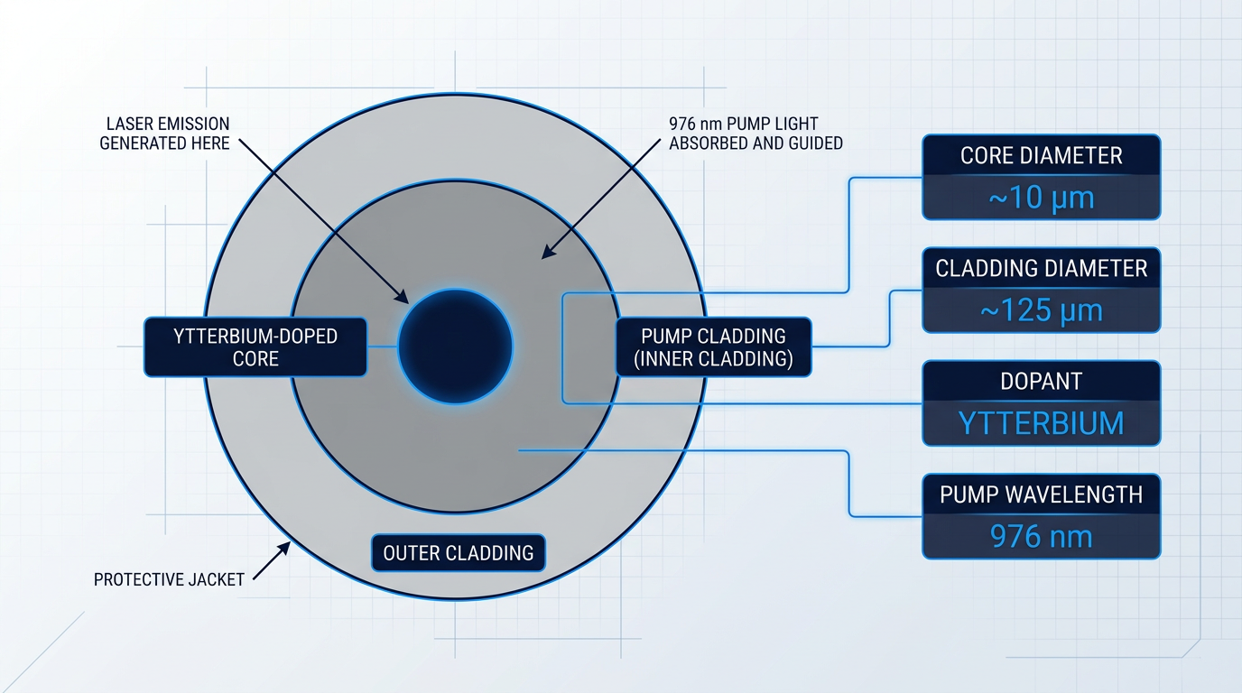
At its core, a fibre laser uses a length of ytterbium-doped silica optical fibre as the gain medium, pumped by diode lasers operating around 976 nm. Ytterbium is the dominant dopant for industrial fibre lasers because its small quantum defect — the energy gap between pump photon and output photon — is only around 6%, which is a key reason the architecture is so efficient.
Double-clad fibre: power and beam quality together
The enabling geometry is the double-clad fibre: an ytterbium-doped inner core surrounded by a larger inner cladding (the pump cladding), itself enclosed in an outer cladding.
Pump light from the diode sources is launched into the large-cross-section inner cladding, where it is guided along the fibre length and gradually absorbed by the doped core — while laser emission builds exclusively in the much smaller inner core.
This arrangement is what allows fibre lasers to combine high output power with excellent beam quality: the pump light is captured efficiently in a large waveguide, but the laser output emerges from a single-mode or near-single-mode core.
Fibre Bragg gratings (FBGs) — periodic refractive-index structures written directly into the fibre — replace the conventional end mirrors of the laser cavity: a high-reflectivity FBG at one end and a partial-reflectivity output coupler FBG at the other define the resonator with no free-space optical components whatsoever.
The practical consequence is significant: there are no mirrors to align, no alignment-sensitive components to drift, and no moving parts in the beam path — which is the architectural reason fibre lasers can operate for years without the routine optical maintenance that CO2 and lamp-pumped systems require.
From the laser source, the output travels through a passive (undoped) delivery fibre to the processing head — a fundamentally different arrangement from CO2 lasers, where the beam travels through free space via a series of beam-bending mirrors between the resonator and the cutting head.
The delivery fibre is flexible, can be routed around obstacles, and can extend tens of metres without alignment or maintenance requirements. This also enables beam-switching configurations, where a single laser source serves multiple processing heads.
Wavelength, beam quality, and why both matter
Ytterbium fibre lasers emit in the near-infrared at approximately 1,030–1,070 nm — confirmed across IPG Photonics and Coherent's technical documentation as the operating range for industrial Yb-doped fibre systems.
CO2 lasers, by contrast, emit at 10.6 µm: a wavelength roughly ten times longer. That difference is not neutral — the shorter 1 µm wavelength is far better absorbed by metals, and it can be focused to a smaller spot size, both of which carry direct processing implications covered in the material compatibility section later in this guide.
Beam quality is quantified by two related metrics: M² (the beam quality factor, where M²=1 represents a perfect diffraction-limited Gaussian beam) and BPP (beam parameter product — the product of beam radius and half-divergence angle, measured in mm·mrad).
Single-mode fibre lasers achieve M² values close to 1, enabling very small focused spot sizes and correspondingly high power density at the workpiece — which translates in practice to finer cutting kerfs and greater precision without requiring higher total output power.
The efficiency advantage of the ytterbium fibre architecture is substantial and well-documented across manufacturer and trade-press sources.
Lamp-pumped Nd:YAG lasers convert roughly 2% of electrical input into laser output. CO2 lasers reach around 7–10%. Ytterbium fibre lasers achieve wall-plug efficiency of 25–57%, depending on design — with IPG's ECO series exceeding 50%. Less waste heat means smaller cooling infrastructure and meaningfully lower operating costs.
The wall-plug efficiency advantage is an architectural consequence of the small quantum defect, the high optical-to-optical conversion efficiency of the double-clad geometry, and the efficiency of the diode pump sources — not a feature that varies by product line.
Fibre laser architecture is also mature, field-proven technology. Single-emitter pump diodes — the components most critical to system longevity — have demonstrated mean time between failure (MTBF) values of 200,000 to 375,000 hours or more in published reliability data from IPG Photonics, Coherent, and Laser Focus World.
The sealed, all-fibre beam path removes the routine maintenance tasks that CO2 systems require: no mirror cleaning, no resonator realignment, no gas management, and no lamp replacement cycles.
With the architecture established, the natural next question is what those engineering choices actually deliver under real industrial operating conditions — which is where the next section picks up.
How fibre lasers deliver industrial performance
Understanding the architecture of an industrial fibre laser is one thing; understanding what that architecture actually delivers on the factory floor is another. The doped fibre core, the diode pumping, the all-fibre beam path — each of these has a direct performance consequence that shows up in specifications, machine comparisons, and day-to-day operation. Those consequences are worth working through carefully, because they explain why fibre lasers behave the way they do, not just that they do.
Power scalability and the modular architecture advantage
At high output levels, fibre lasers are not monolithic devices — they achieve their power by combining the outputs of multiple fibre modules, a technique known as power combining or beam combining.
This modular architecture has a practical consequence that buyers rarely see highlighted in datasheets: there is no single point of failure. If one module degrades, the system can continue operating at reduced power rather than shutting down entirely — a meaningful operational difference from the single-resonator architecture of CO2 and Nd:YAG systems, where failure in the gain medium halts the machine.
The scalability range this enables is wide: from sub-watt fibre laser marking systems at the low end, through to multi-module systems delivering output powers exceeding 100 kW at the high end, with single-mode output to 10 kW and multimode configurations reaching 100 kW and beyond now available commercially.
Beam quality: BPP and what it means in practice
The previous section introduced beam parameter product (BPP) as the key measure of beam quality — lower values indicate a more focusable beam. The performance consequence of fibre lasers' near-diffraction-limited BPP becomes clear when set against the alternatives.
| Laser Technology | BPP (mm·mrad) | Wall-Plug Efficiency |
|---|---|---|
| Yb:Glass Fibre | ~0.34 | 20–30% |
| CO2 | ~6.0 | ~10% |
| Diode-pumped Nd:YAG | ~12 | ~6% |
| Lamp-pumped Nd:YAG | ~25 | ~1% |
Comparison of beam parameter product (BPP) and wall-plug efficiency across laser technology categories, using figures from the Coherent application note.
The BPP gap is substantial: a Yb:Glass fibre laser achieves a BPP of approximately 0.34 mm·mrad, compared to around 6.0 mm·mrad for CO2 and 25 mm·mrad for lamp-pumped Nd:YAG. In practical terms, a lower BPP means the beam can be focused to a smaller spot diameter at the workpiece — and a smaller spot at the same average power means higher power density concentrated into a tighter area.
This is not an incremental difference: the fibre laser's focused spot can be an order of magnitude smaller than that achievable with a CO2 laser of equivalent power, enabling finer cuts, more precise welds, and substantially higher processing speeds for the same wattage delivered to the machine.
Depth of focus and process consistency
High beam quality also delivers a significantly greater depth of focus (DOF) — the axial range over which the beam remains well-focused at the workpiece. Fibre lasers achieve 10–30 times greater depth of focus than CO2 lasers at equivalent spot size.
To put that in concrete terms: at a 200-micron focused spot, a Yb:Glass fibre laser achieves a depth of focus of approximately 58.8 mm, compared to around 3.3 mm for a CO2 laser at the same spot size — a difference of nearly 18 times.
For buyers evaluating cutting applications, this matters in two ways. First, when cutting thicker materials, maintaining beam quality and cut consistency over the full depth of the kerf is harder with a short depth of focus. Second, when standoff distance varies — as it does when cutting tube, structural profiles, or uneven surfaces — a longer depth of focus provides greater process tolerance to those variations without degrading edge quality.
Power density: the mechanism behind processing speed
Power scalability and beam quality combine into a single performance outcome: power density at the workpiece. This is the fundamental physical reason fibre lasers cut thin metal faster than CO2 alternatives at equivalent average power.
A 100 W fibre laser output can be focused to spot diameters as small as 5 microns, with corresponding brightness of more than 10⁹ W/cm² — power densities that are simply not achievable with lower-brightness sources at equivalent average power, regardless of how many watts those sources produce.
The absorptivity advantage of the fibre laser's ~1.06 µm wavelength over CO2's 10.6 µm wavelength at metal surfaces reinforces this further: more of the incident energy is absorbed by the workpiece rather than reflected, improving melting efficiency and compounding the speed advantage.
Because power density scales with the inverse square of spot radius, halving the focused spot size quadruples the power density at the workpiece — even with zero increase in average power output. This is the physical mechanism behind fibre lasers' processing speed advantage, and it is why BPP is a more meaningful performance specification than raw wattage when comparing laser technologies.
Thermal management and cooling infrastructure
The wall-plug efficiency figures in the table above carry a direct operational consequence: less waste heat generated per watt of laser output means less cooling infrastructure is required.
At lower power levels, fibre lasers can operate with air cooling alone — eliminating the chillers, coolant circuits, and associated installation complexity that CO2 systems of equivalent power require. The Fabricator's analysis of fibre laser economics notes that a 4 kW CO2 laser consumes around 50–60 kW of electrical power, while a 2–3 kW fibre laser producing equivalent output quality consumes only 10–15 kW, with no optics, gases, or tubes to maintain.
Fibre lasers from 8 to 10 kW require approximately 20% of the floor space of CO2 lasers of similar power — a facility-planning consideration that affects installation cost and ongoing running costs well beyond the laser system itself.
No warm-up, no alignment, no resonator gas
The sealed all-fibre beam path — with no free-space optical components — eliminates an entire class of maintenance tasks that CO2 operators know well.
- No warm-up time: A fibre laser is ready to process immediately from a cold start. CO2 machines historically required around 15 minutes of warm-up before operation could begin.
- No beam alignment: The sealed fibre path has no mirrors to drift. Beam alignments on CO2 machines — a task that can consume several hours per month — are simply not required.
- No resonator gas: Fibre lasers generate the beam within the doped fibre itself, with no lasing gases to replenish, store, or manage. CO2 systems require scheduled gas evacuation and replenishment.
These are engineering facts that follow directly from the architecture: because there are no free-space optics to drift or degrade, and no gas medium to deplete, the system maintains the same beam characteristics and quality at start-up as it had when last shut down — every time, without intervention.
With these performance properties established — power scalability, beam quality, depth of focus, power density, and thermal management — the practical question for buyers is how fibre laser technology compares to the alternatives it has largely displaced across the criteria that matter most: precision, speed by material thickness, operating cost, and maintenance burden.
Fibre Laser vs CO2 vs Plasma: Choosing the Right Technology
Fibre laser, CO2 laser, and plasma cutting are all mature, proven technologies with large installed bases across global manufacturing — none of them is going away, and none of them is universally superior. The question every buyer should be asking is not "which technology is best?" but rather "which technology is right for my material, my thickness range, my quality requirements, and my operating economics?"
The table below compares all three across the evaluation axes that matter most to industrial buyers: precision, material compatibility, speed by thickness, operating cost, maintenance burden, and capital investment.
| Evaluation Axis | Fibre Laser | CO2 Laser | Plasma |
|---|---|---|---|
| Kerf width | ~0.025 in. typical | No widely cited standalone figure; comparable precision to fibre on thin sheet, but data not confirmed from available sources | ~0.150 in. typical; as narrow as 0.05 in. with high-precision systems |
| Part tolerance | ±0.005 in. typical | ±0.005 in. typical | ±0.020 in. typical; ±0.010–0.015 in. with high-precision plasma |
| Material compatibility — metals | All metals including reflective materials (copper, brass, aluminium); 1 µm wavelength absorbed well by all | Ferrous metals, aluminium (with limitations); struggles with highly reflective materials such as copper and brass | Electrically conductive metals only: mild steel, stainless steel, aluminium |
| Material compatibility — non-metals | Cannot cut clear plastics or transparent materials; 1 µm wavelength passes through without absorption | Cuts plastics, acrylics, wood, fabric, composites — genuine advantage over fibre for non-metallic applications | Not applicable; plasma requires electrical conductivity |
| Speed — thin material (up to ~4 mm) | 2–3× faster than CO2 at equivalent power; up to 5× faster at higher power levels | Slower than fibre on thin sheet; speed disadvantage increases as gauge decreases | Competitive but not the fastest option on thin sheet |
| Speed — thick plate (above ~5–12 mm) | Speed advantage narrows significantly above ~4–5 mm; CO2 retains a speed and surface-finish advantage on straight-line cuts in thicker plate | Retains speed and surface-finish advantage on thick plate, particularly above ~5 mm on straight cuts | Competitive across a wide thickness range; practical for mild steel from 0.125 in. to 2 in. thick |
| Indicative operating cost | ~$4/hr (no lasing gas, no mirrors, high electrical efficiency) | ~$20/hr (resonator gas, mirror maintenance, higher electrical consumption) | ~$15/hr (electrode and nozzle consumable replacement) |
| Maintenance burden | No mirror cleaning, no beam alignment, no resonator gas — sealed all-fibre architecture; 50% longer service intervals vs CO2 | Mirror cleaning, beam alignment, resonator gas replacement required — several hours per month of maintenance tasks | Regular electrode and nozzle replacement as consumables erode; electrode life typically 1–2 hrs arc-on time at high power |
| Capital cost | Higher upfront cost than plasma; typically lower than CO2 at equivalent power output | Typically the highest capital cost at equivalent power; a 4 kW CO2 is outperformed by a 2 kW fibre in most categories | Lower initial capital requirement than laser systems; exact ordering vs CO2 varies by configuration |
Multi-axis comparison of fibre laser, CO2 laser, and plasma cutting across the key criteria industrial buyers use to evaluate cutting technology.
The most striking pattern in the data is the operating cost gap: fibre laser at approximately $4/hr versus CO2 at approximately $20/hr represents a five-fold difference in hourly running cost — a gap that compounds dramatically over years of production shifts.
The speed story is more nuanced than it first appears. Fibre laser's advantage is concentrated in thin-to-medium gauge material — up to approximately 4–5 mm, where it can cut 2–3 times faster than a CO2 machine at matched power. Above that threshold, the speed differential narrows, and on thick plate straight-line cuts, CO2 retains a genuine advantage in both speed and surface finish.
Material compatibility is often the axis that settles the decision. Fibre laser's 1 µm wavelength is well-absorbed by all metals, including reflective metals such as copper, brass, and aluminium that CO2 has historically struggled with — the CO2 beam's 10.6 µm wavelength is poorly absorbed by these materials, creating back-reflection risks that complicate the process.
However, fibre laser has a clear limitation on the non-metallic side: the 1 µm wavelength passes straight through clear plastics such as acrylic and polycarbonate without being absorbed, making fibre laser incapable of cutting them. CO2 laser retains a genuine, uncontested advantage for non-metallic materials — plastics, wood, acrylics, fabric, and composites — that fibre simply cannot address.
Plasma's material range sits at the opposite end: it is limited entirely to electrically conductive metals, with no capability on non-metallics and no path to the fine tolerances that precision fabrication demands. Its natural territory is high-volume structural cutting of mild steel, stainless steel, and aluminium where tolerances of ±0.020 in. are acceptable.
On capital investment, the instinct to compare purchase prices is understandable but misleading. A plasma system carries a lower entry cost than laser alternatives, but at approximately $15/hr in consumable and operating costs, it is not cheap to run. Fibre laser's higher purchase price is offset by operating costs that are roughly a quarter of CO2 — and that difference accumulates across every production shift for the life of the machine.
Bystronic's published energy analysis illustrates the scale of the gap: replacing a 6 kW CO2 machine with a 6 kW fibre laser can yield annual electricity savings of $8,000–$15,000 at typical US power rates — and that figure covers energy alone, before accounting for eliminated gas, mirror, and maintenance costs.
The five-fold difference in hourly operating cost between fibre laser (~$4/hr) and CO2 (~$20/hr) is not a marginal efficiency gain — it is a structural cost advantage that compounds across every production shift over the machine's lifetime. Evaluating cutting technology on purchase price alone inverts the economics.
Bringing this together into practical guidance: fibre laser is the dominant choice for precision cutting of thin-to-medium gauge metal, for any application involving reflective materials, and wherever low operating cost and minimal maintenance are priorities. CO2 laser remains the right answer for thick plate cutting where surface finish is critical, and for any operation that regularly processes non-metallic materials. Plasma cutting suits high-volume structural work on conductive metals where capital constraints are a factor and part tolerances in the ±0.020 in. range are sufficient.
With cutting technology selection covered, the next question for most buyers is how broadly fibre laser can be deployed across their manufacturing operations — because cutting is only one of the application areas where industrial fibre lasers deliver value.
Industrial applications of fibre lasers
Ask most people what an industrial fiber laser does and they will say cutting — but cutting is only one of five distinct process categories where fibre laser technology has become the tool of choice. The same fundamental platform that slices through sheet steel is also the dominant technology for permanent metal marking, the primary tool for precision engraving, a growing force in deep-penetration welding of difficult materials, and an increasingly capable solution for surface cleaning that outperforms both abrasive and chemical methods.
Sheet metal cutting
Fibre lasers have become the dominant technology for cutting thin-to-medium gauge sheet metal, and the reason comes down to wavelength: the approximately 1 µm output of a ytterbium fibre laser is absorbed far more efficiently by metals than the 10.6 µm output of a CO2 laser.
That absorption advantage is especially significant for highly reflective metals — copper, brass, and aluminium — which CO2 lasers struggle to process reliably because the reflected beam can damage the laser source itself; fibre laser designs are engineered to be insensitive to back-reflections, opening up these materials to productive cutting.
Power level governs what is achievable: higher average power extends the maximum cut depth and increases cutting speed, with modern systems reaching 24 kW and capable of processing mild steel beyond 25 mm — but the full power-to-thickness relationship is covered in the power selection section that follows.
Marking
Fibre lasers have taken over the majority of permanent metal marking applications, and the pulsed operating regime is the enabling factor: nanosecond pulses deliver high peak power with low average power, giving precise, repeatable results at production speeds without excessive heat input to the surrounding material.
Annealing is the marking mode used where no material removal is acceptable — the laser heats the surface to induce a controlled oxide layer, producing a dark, corrosion-resistant colour change with the surface left intact; this is the standard approach for stainless steel medical instruments and food-contact components.
Ablation marking removes a thin surface layer to expose a contrasting material beneath — the technique behind day/night automotive buttons, where a top coating is removed to allow backlighting.
Shallow engraving marks use slightly more material removal to achieve depth and permanence — useful where the mark must survive subsequent painting or surface treatment, such as vehicle identification number (VIN) marking where depth provides both visibility and security.
The controllability of MOPA-based nanosecond fibre lasers — with pulse durations tunable across a wide range and repetition rates from 1 kHz to 1 MHz — means a single laser source can switch between these modes by adjusting parameters rather than changing equipment, which is a practical throughput advantage in mixed-production environments.
Engraving
Where marking creates a surface effect, engraving involves genuine material removal to create a changed profile in the substrate — relief features, logos, serial numbers, and decorative patterns that have measurable depth.
Nanosecond pulsed fibre lasers are the primary tool for this work: each pulse creates a small melt pool, surface vaporisation generates recoil pressure, and the resulting melt ejection removes material — a process that repeats cycle by cycle, removing material layer by layer until the required depth is reached.
The central challenge in deep engraving is thermal management: accumulated heat at the workpiece degrades edge quality and risks substrate damage, which is why quality engraving work typically operates in the 50–100 W average power range rather than simply maximising power.
It is the high peak power of the pulsed regime — not average power — that enables clean ablation at depth: peak powers above 20 kW allow fibre lasers to compete directly with lamp-pumped Nd:YAG engravers that were previously the standard for intricate mould tool work and similar demanding applications.
Welding
Fibre lasers enable deep-penetration welding through the keyhole mechanism: the combination of high beam brightness and a tightly focused spot creates power densities above 1 MW/cm², vaporising metal to form a vapour-filled cavity that the beam tracks into the material, producing weld depths far greater than conventional arc processes at equivalent speeds.
This capability extends to materials that are difficult or impossible to weld reliably by other methods — copper and aluminium in particular, where the high reflectivity at room temperature is overcome by the power density available from a focused single-mode fibre laser, with absorption in the molten or evaporated metal rising to over 60% once the keyhole is established.
Wobble welding addresses the porosity and fit-up challenges that can arise with keyhole welding: an oscillating beam path — controlled by scanning mirrors inside the weld head — passes near any given point of the weld multiple times, slowing temperature ramp rates, reducing spatter, and allowing a 2–3× increase in acceptable seam gap compared with conventional laser welding.
The practical significance of copper and aluminium welding capability is most visible in EV battery manufacturing and heat exchanger production, where joining dissimilar conductive materials in high volume is a core process requirement — sectors where fibre laser welding with wobble-head technology is displacing earlier approaches.
Laser cleaning
Laser cleaning works by selective ablation: a pulsed laser beam vaporises the surface contaminant layer — rust, oxides, mill scale, paint, release agents, carbon deposits, and similar — while leaving the substrate beneath intact, because the contaminant's ablation threshold is lower than that of the base material and the beam effectively stops when it reaches the substrate.
This selectivity is what distinguishes laser cleaning from abrasive blasting, which causes surface damage and generates waste media requiring disposal, and from chemical stripping, which cannot be easily targeted to a specific area and requires solvent handling and disposal; laser cleaning removes only what needs to be removed, with no consumables and minimal substrate loss.
For on-site and flexible cleaning work, handheld portable systems allow the operator to bring the machine to the part rather than the reverse — the typical use case for maintenance, pre-weld preparation in the field, and heritage restoration. Woodrow Scientific's ELASER, for example, is an air-cooled, consumable-free system with a handheld scanner weighing under 3 kg and a delivery cable reaching up to 50 m, making it a single-operator tool with genuine field reach.
The ELASER-RHZ variant carries Woodrow Scientific's world-first patented eye-safe Reduced Hazard Zone (RHZ) technology, which collapses the laser hazard zone to a fraction of the size required by conventional laser cleaning systems — enabling cleaning in open workshops, mixed-use facilities, and publicly accessible environments where conventional laser cleaning would require full area evacuation and shutdown.
For production cleaning at volume, automated robotic systems remove manual labour from repetitive cleaning tasks while holding a consistent standard on every cycle — injection mould cleaning, automotive component preparation, and aerospace surface treatment are all well-established use cases. Woodrow Scientific's AutoLASE illustrates what is possible at the leading edge of this category: simply load the part, and the system's machine-vision software scans it, builds a 3D map, and generates the cleaning path automatically — no manual programming, no knowledge of part geometry, no specialist skills required.
AutoLASE can also be configured with the RHZ upgrade, enabling enclosure-free automated cleaning — a capability exclusive to Woodrow Scientific that removes the requirement for a sealed cell around the robot.
Conventional laser cleaning requires areas to be sealed off and evacuated before work can start. Woodrow Scientific's patented RHZ technology collapses the hazard zone to a fraction of conventional size, unlocking laser cleaning in open, shared, and public environments where it was previously impractical — for both handheld and automated deployments.
Across cutting, welding, and cleaning in particular, a single fibre laser platform operating at different power configurations can serve multiple process types within the same facility — a capital investment argument that single-application machines cannot match, since the platform's flexibility means it can be redeployed as process requirements shift rather than becoming a stranded asset.
Knowing what fibre lasers can do is, however, only part of the evaluation picture — the other half is understanding which materials they process effectively and where the technology's limits lie, which is the focus of the next section.
What Fibre Lasers Can and Cannot Process
The 1 µm wavelength that defines industrial fibre laser technology is the single most useful lens through which to understand material compatibility — it explains both why fibre lasers dominate metal processing and where they genuinely fall short. This section maps that out concretely, so you can match the technology against your own application before going further.
Fibre lasers process the full range of industrial metals: mild steel, stainless steel, aluminium, titanium, copper, brass, bronze, cast iron, and nickel alloys. Metals as a class absorb near-infrared wavelengths efficiently, and the 1 µm output gives fibre lasers a meaningful absorption advantage over CO2's 10.6 µm wavelength across this entire material group.
Reflective Metals: The Headline Differentiator
Copper, brass, and aluminium are the materials where the wavelength difference between fibre and CO2 matters most in practice. At CO2's 10.6 µm wavelength, these metals are highly reflective — copper and brass cutting with a CO2 laser was historically rare, and aluminium cutting remained, as The Fabricator describes it, "a little like squeezing a small round peg in a larger square hole." At the 1 µm fibre wavelength, all three absorb far more energy and reflect far less, enabling clean, high-speed cuts that CO2 cannot reliably achieve.
This absorption advantage has direct industrial consequences: EV battery manufacturing relies on fibre lasers to cut electrode foils and weld copper and aluminium tabs, busbars, and cell connectors; heat exchanger fabrication uses fibre laser welding for thin stainless steel and aluminium sheet; and decorative metalwork in copper and brass is processed routinely on fibre platforms where CO2 would struggle.
Copper, brass, and aluminium absorb the 1 µm fibre laser wavelength far more effectively than CO2's 10.6 µm — this single physical fact is why fibre laser has become the default choice for EV battery component manufacturing and heat exchanger fabrication.
Anodised, painted, film-coated, and galvanised metals are all processable with fibre lasers, which is practically significant for fabricators working with pre-treated sheet who need to cut or weld without stripping coatings first. One consideration worth noting: processing coated metals generates fumes specific to the coating material, and appropriate extraction is required — fume management is covered in the buying considerations section.
Where Fibre Lasers Have Limits: Non-Metallic Materials
Fibre lasers can process some non-metals, but the distinction between processable and non-processable is sharp and matters for buyers with mixed-material applications. The core issue is that the 1 µm near-infrared wavelength passes through many transparent and organic materials without being absorbed — meaning the laser delivers no useful energy to the workpiece.
- Silicon: Processable with fibre lasers, including scribing and micromachining of silicon substrates used in electronics.
- Ceramics: Processable using near-infrared fibre lasers with surface preparation techniques; pulsed fibre lasers offer finer features than CO2 for ceramic scribing.
- Carbon-fibre composites (CFRP): Processable with fibre lasers; high beam quality and small spot size help manage thermal damage in these temperature-sensitive materials.
- Pigmented or filled plastics: Processable when additives such as carbon black provide sufficient near-IR absorption; clear or unpigmented plastics are not suitable.
- Clear acrylic (PMMA) and polycarbonate: Not processable — these transmit near-infrared rather than absorbing it. CO2 is the correct tool for cutting clear plastics.
- Wood, MDF, and organic materials: Not processable effectively with fibre lasers. CO2's 10.6 µm wavelength is strongly absorbed by organics; fibre is not.
For buyers with mixed metal and non-metal requirements, this is a genuine platform decision: a single fibre laser system will not cover thick acrylic cutting, wood routing, or most textile processing. CO2 retains a clear advantage for non-metallic cutting in the majority of cases, and buyers should assess whether their application mix warrants a dedicated CO2 platform alongside a fibre system.
Pulsed fibre lasers also process stone, brick, masonry, and concrete — relevant primarily to cleaning and surface preparation applications in infrastructure maintenance and heritage restoration, rather than structural cutting.
Cutting Thickness Capability by Power Level
Cutting depth scales directly with available power, and the table below gives indicative thickness ranges for mild steel — the most common reference material across the industry. These figures are drawn from published cutting data and machine specifications from Trumpf, Bystronic, and Laser Focus World research, and should be read as a scoping framework rather than guaranteed specifications for any individual machine.
| Power Level | Mild Steel (indicative max) | Stainless Steel (indicative max) | Notes |
|---|---|---|---|
| 6 kW | ~25 mm | ~15 mm | Nitrogen cutting to ~6 mm; oxygen assist required beyond that for mild steel |
| 10 kW | ~25 mm | ~30 mm | 10 kW machine documented cutting 10 mm mild steel at ~5 m/min with nitrogen |
| 12 kW | ~30 mm | ~30 mm | 12 kW documented cutting mild steel up to 30 mm thick |
| 24 kW | up to 60 mm | up to 60 mm | TruFiber 24001 documented cutting mild steel/stainless/aluminium 1–60 mm |
Indicative cutting thickness capability by fibre laser power level for mild steel, with stainless steel reference data where available from published sources.
The pattern across these figures is consistent: cutting thickness capability grows with power, but the relationship is not linear, and the assist gas used interacts significantly with achievable thickness and edge quality. Nitrogen produces oxide-free edges suited to powder coating and welding but has a lower thickness ceiling at a given power level; oxygen extends thickness reach for mild steel but at slower speeds and with an oxidised edge. These trade-offs are explored in detail in the power levels section.
One buying consideration specific to reflective metal cutting deserves attention here: early fibre laser architectures were sensitive to back-reflections from highly polished surfaces, where reflected laser energy travelling back into the fibre could damage the gain medium. Modern fibre laser designs address this through integrated back-reflection isolators — hardware-based systems that strip reflected light and direct it to a water-cooled beam dump rather than allowing it to interact with the fibre. Buyers evaluating equipment for copper cutting or mirror-finish stainless work should specifically confirm that the system they are considering incorporates this protection, as implementations vary across manufacturers and product lines.
The thickness ranges above are ultimately a function of available power — and power selection involves much more than a single material thickness figure. The next section maps the full fibre laser power spectrum, from sub-100 W precision systems through to ultra-high-power platforms exceeding 20 kW, giving buyers a structured framework for interpreting power specifications against their application requirements.
Power levels and their industrial use cases
A spec sheet that reads "6 kW fiber laser" or "100 W marking system" tells you almost nothing on its own. Power figures only become meaningful when you know what application they serve, what pulse regime they operate in, and what material thickness or area rate they need to achieve. The table below maps the full power spectrum of industrial fiber laser systems to the applications and use cases each tier serves — giving you a practical framework for reading any laser specification.
Use this as a reference when evaluating systems: the tier a machine sits in tells you its primary application logic, the dominant pulse regime, and the performance parameters that actually govern suitability.
| Power Range | Pulse Regime | Primary Applications | Indicative Use-Case Examples |
|---|---|---|---|
| Sub-100 W | Pulsed (nanosecond) | Precision marking, fine engraving, precision cleaning of sensitive substrates | Component ID marking, fine engraving on jewellery/electronics, cleaning delicate surfaces without bulk heating |
| 100 W – 1 kW | Pulsed or CW | Production-speed marking, surface cleaning and preparation, thin-section cutting, light welding | Portable and semi-automated laser cleaning systems, thin foil cutting, handheld laser welding up to ~9-gauge steel |
| 1 kW – 6 kW | CW | Sheet metal cutting (thin-to-medium gauge), structural welding | Fabrication shops cutting mild steel, stainless, and aluminium; 6 kW cuts mild steel up to ~25 mm with oxygen assist |
| 6 kW – 10 kW | CW | Medium-to-thick plate cutting, higher throughput fabrication | 10 kW cuts mild steel up to 25 mm and stainless up to 30 mm; nitrogen cutting viable up to ~10 mm at 10 kW |
| 10 kW – 30 kW+ | CW | Thick plate and structural steel cutting, challenging plasma on heavy sections | Ultra-high-power systems reaching 30 kW; 30 kW doubles cutting speed vs 15 kW on 6–15 mm structural steel |
| Multi-kW CW (welding) | CW | Deep-penetration (keyhole) welding of structural metals | 20 kW CW fiber laser welding 1-inch stainless steel at 0.85 m/min; heavy fabrication and pressure vessel joining |
| Hundreds of W (welding) | Pulsed or CW | Fine welding of medical devices, electronics, precision assemblies | CW fiber up to ~500 W for seam welding; nanosecond pulsed for thin-material joining with minimal heat input |
| 20 W – 1 kW+ (cleaning) | Pulsed | Precision cleaning of sensitive substrates through to large-area industrial decoating | Low-power pulsed for substrate-sensitive applications; 1–3 kW pulsed systems for high-area-rate paint and oxide removal |
Maps the full industrial fiber laser power spectrum to primary applications, pulse regime, and indicative use-case examples — giving buyers a scannable reference for interpreting power specifications.
The clearest pattern in this table is the shift from pulsed operation at low power to continuous wave (CW) as power scales into the kilowatt range — and with that shift comes a fundamental change in application logic.
At sub-100 W, average power is almost irrelevant. What matters is peak power and pulse control: nanosecond pulsed lasers in this range can deliver very high instantaneous power at the workpiece despite low average output, enabling precise material interaction without bulk heating. The governing parameters are pulse energy, pulse duration, and repetition rate — not the watt figure on the label.
Moving into the 100 W to 1 kW range, the application logic shifts toward throughput. This is the primary power band for portable and semi-automated laser cleaning systems, production-speed marking, and light welding. Air-cooled operation remains viable through much of this range, which keeps system footprint and infrastructure requirements manageable — a meaningful consideration for buyers evaluating cleaning or marking systems that need to move between workstations.
The 1 kW to 10 kW range is the core domain of sheet metal cutting. Within this band, 2–6 kW represents the workhorse tier for fabrication shops processing thin-to-medium gauge steel, stainless, and aluminium. Higher power within this range extends thickness capability and increases cutting speed on heavier material — but the relationship is not linear and depends heavily on assist gas selection.
The interaction between power and assist gas type is a critical axis buyers often overlook. Nitrogen cutting produces clean, oxide-free edges but has a thickness ceiling that scales roughly with power: at 6 kW, nitrogen cutting is viable to around 6 mm, rising to approximately 10 mm at 10 kW. Beyond those thresholds, oxygen assist is required — but oxygen cutting speed does not increase with power in the same way, which limits the productivity benefit of higher power on thicker sections cut with oxygen.
Ultra-high power: the 10 kW+ cutting frontier
The rapid development of ultra-high-power (UHP) fiber laser cutting has been one of the most significant shifts in fabrication over the past decade. Maximum cutting power available on production machines has risen from 6 kW in 2015 to 40 kW by 2022 — a nearly sevenfold increase in seven years.
At these power levels, a new assist gas regime becomes viable: high-pressure air. UHP lasers at 30–40 kW can cut thick carbon steel with air assist at speeds up to 4–5 times faster than oxygen cutting, while delivering dross-free edges — a combination that fundamentally changes production economics for fabricators processing structural plate.
Bystronic's ByStar Fiber and ByCut Star both reach 30 kW, with Bystronic's own product pages confirming that the 30 kW ByCut Star more than doubles cutting speed compared to a 15 kW machine on structural steel between 6 mm and 15 mm thick — and exceeds double the speed on sections above 20 mm.
At this power tier, fiber lasers begin to challenge plasma cutting on thick plate — a meaningful reversal of the traditional positioning of these technologies, where laser was considered the thin-sheet tool and plasma owned the heavy-section market.
Welding and cleaning: power sub-regimes that matter
Welding applications split into two distinct power sub-regimes with very different specification requirements. Deep-penetration keyhole welding of structural metals requires multi-kilowatt CW fiber lasers: IPG's application work demonstrated 20 kW CW fiber laser welding of 1-inch stainless steel at 0.85 m/min, with penetration depths achievable that previously required electron beam equipment.
Fine welding of medical devices, electronics, and precision assemblies operates in the hundreds-of-watts range, where precise pulse control matters far more than raw power. CW fiber lasers under 500 W are well suited to high-speed seam welding up to ~1.5 mm penetration; nanosecond pulsed fiber lasers offer sub-400 ns pulse control for thin-material joining with minimal heat-affected zone.
Buyers evaluating welding applications must specify not just power level but whether they need CW or pulsed operation — the two regimes produce fundamentally different material interactions, and a system optimised for one is rarely optimal for the other.
The laser cleaning power spectrum spans an equally wide range. At the low end, pulsed systems in the tens of watts are used for precision cleaning of substrate-sensitive components, where the priority is selective removal of contaminants without affecting the underlying material. At the high end, pulsed systems from 1 kW to 3 kW are used for large-area industrial decoating and surface preparation, where area rate is the primary driver. Laser Focus World has noted cleaning systems with powers from 20 W up to 1 kW in commercial use, with higher-power systems in development.
For cleaning, the right power level is governed by contaminant type, coating thickness, substrate sensitivity, and required area rate — not a single universal figure. A 200 W pulsed nanosecond system can achieve cleaning rates of approximately 2 m²/h on aluminium alloy; scaling power increases area rate, but substrate sensitivity may impose an upper limit before power capacity does.
Across all applications, the table and analysis above give you the power-tier framework. But power alone does not close the specification.
Power sets the ceiling on what a fiber laser can do. Beam quality (M² or BPP) determines the minimum achievable spot size and therefore power density at the workpiece. Pulse regime (CW vs pulsed, nanosecond vs picosecond) determines the nature of the material interaction. Duty cycle determines whether the system can sustain rated power through a full production shift. Buyers who evaluate on power alone risk misspecifying — sometimes by a wide margin.
A system with poor beam quality cannot focus its rated power to the spot size needed for a given application — the power is there, but it cannot be delivered where it matters. A system with the right power but the wrong pulse regime will produce the wrong material interaction entirely. These are the axes that the buying considerations section develops in full — but they are worth naming here, because they are what separates a well-specified system from an expensive mistake.
Understanding how power tiers map to applications is the first step; understanding how the full operational specification fits your production environment is the next — and that is where workflow integration and system selection criteria come into focus.
Integration with manufacturing workflows and Industry 4.0
Knowing which power level suits your application is one thing; knowing how an industrial fiber laser slots into your production environment is another question entirely. The machine itself is only part of the investment — how it connects to your CNC control platform, your ERP system, and your automation infrastructure determines whether it becomes a productivity multiplier or an expensive bottleneck sitting in the middle of a manually managed workflow.
CNC compatibility and CAD/CAM integration
For fabrication shops that already run CNC machining or punching, workflow continuity is the central integration question: can part programmes flow from CAD through nesting to the laser without manual re-entry or format translation at each step?
The answer depends heavily on whether the laser system uses an open control architecture or a proprietary one. Open platforms — such as PC-based control built on standards like EtherCAT — allow engineers to program in established languages, connect to higher-level software via documented interfaces, and add capability as requirements evolve without being locked to a single vendor's upgrade cycle.
A proprietary control script, by contrast, creates friction at every integration point: custom post-processors, manual workarounds, and a ceiling on what the system can do as your workflow matures. Buyers should ask vendors directly whether the control platform uses open, documented interfaces — and treat vague answers as a signal worth investigating further.
On the software side, modern CAD/CAM systems for laser cutting consolidate design, nesting, NC code generation, and cutting parameter management into a single environment. Mazak's SMART SYSTEM, for example, imports drawings directly into the CNC system, generates optimised nesting data instantly, and the company reports lead time reductions of over one-quarter compared to conventional sequential CAM workflows.
Software-driven automation: the baseline, not the premium
Modern fibre laser cutting machines handle a range of setup and monitoring tasks automatically — and buyers should expect these capabilities as standard, not as add-ons that justify a price premium.
According to Bystronic, fully automated systems now perform automatic focal adjustment, nozzle selection, nozzle centring, and nozzle calibration without operator intervention, and continuously monitor cut kerf quality to detect and correct irregularities in real time. Combined with automated material handling, this makes unmanned off-shift and weekend operation consistently achievable — not an experimental mode.
If a vendor positions automated focal adjustment, nozzle calibration, or cut-quality monitoring as optional upgrades, that framing warrants scrutiny: it may reflect an equipment architecture that was not designed for automation from the ground up, or a commercial strategy of unbundling capabilities that well-engineered systems include by default.
ERP and MES integration
Connecting a laser cutting system to ERP and MES software transforms it from a standalone machine into a node in a production system. Real-time order tracking, material inventory management, nesting driven by live job queues, and throughput monitoring all become possible — and the impact on effective output can be substantial.
The practical evidence for this is not theoretical. Online Laser, a UK sheet metal fabricator, reported doubling its production output after integrating CAD/CAM and ERP software with its two fibre laser cutters — moving from difficulty managing 100 live orders to handling more than 200, while compressing job quoting from several days to as little as one to two hours.
The mechanism is straightforward: without ERP/MES integration, machine scheduling and material flow are managed manually, which introduces bottlenecks that the laser's speed immediately exposes. A high-power fibre laser can process material faster than a manually managed front end can feed it jobs — so the machine waits, and the throughput advantage is lost.
With integration in place, the ERP generates bills of materials and material requirements, the MES routes jobs to the correct machine based on capability and schedule, and the CAD/CAM system nests parts automatically against live order data. The laser becomes the pull point in a connected production system rather than a machine that operators keep busy by hand.
Connectivity and remote monitoring
Modern industrial fiber laser equipment supports cloud-connected condition monitoring, predictive maintenance alerts, and remote diagnostics — capabilities that are increasingly relevant as manufacturers manage multi-machine or multi-site operations.
Trumpf's Condition Monitoring platform, for example, connects laser systems to a Predictive Service Centre via an encrypted cloud gateway using OPC UA and standard HTTPS protocols. Algorithms and service experts analyse machine-state data continuously, flagging anomalies — such as a cooling water level dropping faster than expected — before they cause unplanned downtime. Trumpf reports that approximately 70% of issues can be resolved remotely without a site visit.
The architecture question matters as much as the capability itself. Open, standards-based connectivity — using protocols like OPC UA that allow integration with third-party monitoring systems — gives buyers flexibility to incorporate laser data into their own production dashboards or MES platforms. Proprietary connectivity that routes all data exclusively through a vendor's cloud creates dependency and limits what you can do with your own machine data.
Ask vendors whether their connectivity platform uses open standards (such as OPC UA) or proprietary protocols. Open standards let you integrate laser condition data into your own MES or monitoring systems; proprietary data silos limit that flexibility permanently.
Robotic integration and flexible beam delivery
The flexible fibre delivery cable is the physical enabler that makes robot-mounted laser heads practical. Because the beam travels through a flexible optical fibre rather than a fixed free-space beam path, a processing head can be mounted on a six-axis robot arm and moved through complex three-dimensional trajectories without the alignment constraints that would apply to a CO2 or bulk solid-state laser.
This makes fibre laser systems well suited to remote laser welding and 3D cutting of complex geometries — applications where the robot positions a scanner optic or programmable focusing optic at the end of the fibre cable and steers the beam across the workpiece at high speed. In automotive body-in-white production, this approach has demonstrated production time reductions of up to 80% compared to conventional resistance spot welding, with one remote laser welding station replacing up to five spot welding stations.
For buyers evaluating fibre lasers for welding or 3D cutting applications, the practical implication is that the laser system's fibre interface and the robot controller need to be synchronised — axis coordination between the robot and the scanner control is a prerequisite for on-the-fly processing. This is a systems integration task, not just a machine purchase.
Setup complexity: planning for a complete installation
Adding a fibre laser to an existing production line involves more than the machine footprint and the purchase price. Buyers who treat the infrastructure requirements as an afterthought typically discover them as project delays. The elements below are planning requirements, not reasons to hesitate — but they need to be in the project scope from the start.
- Fume extraction and filtration: Laser cutting and welding produce fine particulate and vapours that must be captured at source and filtered to meet OSHA permissible exposure limits. High-efficiency cartridge filtration (MERV16 or equivalent) is typically required, with air-to-cloth ratios sized for the cutting volume and material types processed.
- Laser safety enclosures: Class IV laser systems require interlocked enclosures with warning light assemblies, emergency disconnect interlocks, and controlled-access procedures. Class 1 workstation classification — which removes many of these requirements — demands a light-tight enclosure designed and tested by the system integrator.
- Electrical supply infrastructure: High-power fibre laser cutting systems draw significant electrical load. Trumpf's own data shows average production power consumption of 10–16 kW for 4–12 kW laser systems, requiring appropriately sized three-phase supply, conductor cross-section, and fuse protection per NEC requirements.
- Cutting gas and compressed air supply: Nitrogen and oxygen assist gas supply infrastructure, plus compressed air at sufficient pressure and flow rate, must be installed and sized before commissioning. These are facility modifications, not machine accessories.
- Operator training: Class IV laser operation requires trained personnel with a working understanding of laser safety, standard operating procedures, and emergency controls. Training is a regulatory requirement, not an optional add-on.
- Workflow re-sequencing: A high-speed fibre laser changes the throughput balance of an entire production line. Downstream operations — bending, welding, sorting — need to be assessed and potentially re-sequenced to prevent the laser from creating new bottlenecks elsewhere in the shop.
The installation timeline for a high-power fibre laser system typically involves parallel preparation tracks: site preparation, electrical and gas supply installation, fume extraction design, and safety enclosure specification all need to be underway before the machine arrives. Compressing this preparation is the most common cause of delayed commissioning.
Automation-readiness as a non-negotiable criterion
The practical conclusion from all of the above is that CNC compatibility, open control interfaces, and automation integration should be treated as non-negotiable baseline criteria when evaluating fibre laser equipment — not as features to be traded off against price.
Equipment that positions these capabilities as optional extras, or that uses proprietary control scripts and closed connectivity architectures, creates vendor lock-in that limits your ability to evolve the production system over time. The machine you buy today needs to be able to talk to the ERP system you implement in three years, the MES you upgrade in five, and the monitoring infrastructure your customers may eventually require as a supply chain condition.
Buyers who ask hard questions about control architecture and connectivity during evaluation protect their future flexibility. Those who accept vague answers at the point of purchase often discover the cost of that flexibility later — when a software upgrade requires a full control system replacement, or when machine data cannot be extracted for their own production analytics.
With the operational integration picture now established, the next dimension of the evaluation framework is environmental: how fibre laser technology performs on energy efficiency, consumable use, and the sustainability metrics that are increasingly part of manufacturing investment decisions.
Sustainability and Environmental Considerations
When a 6 kW fibre laser cutting machine draws approximately 22 kW average from the wall — and a comparable 6 kW CO2 machine draws approximately 65 kW for the same output — that is not a marginal efficiency gain. It is a factor of three in energy consumption, with direct consequences for electricity bills, transformer infrastructure, chiller sizing, and carbon footprint. This is an engineering fact, not a marketing position, and it is the most concrete sustainability argument in the industrial laser technology stack.
Wall-Plug Efficiency: The Numbers Behind the Gap
The efficiency advantage traces directly to the technology's architecture. Ytterbium-doped fibre lasers convert electrical input to usable optical output at wall-plug efficiencies of 25–50% or higher, with leading designs exceeding that range. CO2 lasers operate at roughly 10%, and Nd:YAG lasers at approximately 1–6% — meaning the vast majority of their electrical input is lost as heat rather than delivered as usable laser power.
| Laser Technology | Wall-Plug Efficiency | Avg. Power Draw (6 kW machine) | Annual Consumption (3,600 h/yr, 65% duty) |
|---|---|---|---|
| Fibre laser (Yb-doped) | 25–50%+ | ~22 kW | ~51,480 kWh |
| CO2 laser | ~10% | ~65 kW | ~152,100 kWh |
| Nd:YAG laser | ~1–6% | Significantly higher than CO2 | Not directly comparable at 6 kW |
Comparison of laser technology types by wall-plug efficiency and real-world power draw at equivalent 6 kW output power, to quantify the energy consumption gap.
At a modest electricity rate of €0.25/kWh, the 100,620 kWh annual saving between a 6 kW fibre and a 6 kW CO2 machine translates to roughly €25,000 per year — and at higher industrial tariffs, that figure rises steeply. Over a five-year asset life, the cumulative energy saving alone can exceed €125,000 at conservative rates, making the energy efficiency advantage a substantive input to any total cost of ownership calculation.
A 6 kW CO2 laser machine consumes approximately 65 kW average from the wall. A 6 kW fibre laser delivers the same cutting power for approximately 22 kW — roughly one third of the energy draw. That difference compounds across every hour of production.
The efficiency gap also has infrastructure implications that rarely appear in headline comparisons. Lower electrical draw means reduced transformer capacity requirements, smaller chiller units, and lower heat rejection into the factory environment — all of which reduce both capital outlay and ongoing facility running costs.
Eliminating Consumables and Their Waste Streams
As covered in the technology architecture and maintenance sections of this guide, fibre lasers require no CO2 resonator gas, no beam-delivery bellows, and no mirror replacements. The environmental consequence of that architecture is the elimination of several recurring material inputs and their associated waste streams from the production process.
In practice, this means no gas cylinder deliveries and their transport emissions, no spent mirror disposal, and no bellow replacement cycles. These may seem like minor operational details individually, but across a production facility running multiple shifts over years, the cumulative reduction in consumable waste is a genuine and measurable environmental benefit — not an incidental one.
Laser Cleaning: A Zero-Consumable Process
The sustainability case is most striking in the laser cleaning application. Where the process was covered earlier in this guide in terms of what it does, the environmental dimension deserves separate attention: laser cleaning uses photonic energy alone, with no chemicals, no abrasive media, and no water.
The conventional alternatives each generate significant waste streams that require active management. Chemical stripping produces hazardous liquid waste that must be classified, stored, and disposed of under chemical waste regulations. Sandblasting and abrasive blasting generate contaminated spent media — grit, steel shot, or other abrasives mixed with the removed coating — that must be collected and disposed of as industrial waste. Water-jetting produces contaminated effluent that requires treatment before discharge.
- Chemical stripping eliminated: No hazardous liquid waste, no solvent handling, no chemical storage or disposal costs — the entire chemical waste stream is removed from the process.
- Abrasive media eliminated: No spent grit, shot, or blasting media to collect, classify, or dispose of. Contaminated abrasive disposal is a significant cost in high-volume operations.
- Effluent treatment eliminated: No process water, no contaminated wastewater stream, no treatment requirement before discharge. The only output is the removed coating itself, captured by fume extraction.
- Transport emissions reduced: No consumable deliveries, no waste collection logistics — eliminating the CO2 emissions associated with chemical and media supply chains.
The only material output from a laser cleaning process is the removed surface layer itself — typically captured as particulate in a fume extraction system. This makes laser cleaning the only surface preparation method that genuinely eliminates the waste generation problem rather than managing it.
Material Efficiency: Kerf Width and Nesting
Fibre laser cutting's narrow kerf width — typically under 0.5 mm — reduces material loss per cut compared to plasma or oxyfuel processes, where kerf widths of 1–4 mm are common. Advanced nesting software compounds this advantage by arranging parts to maximise utilisation of each sheet, with closer part spacing enabled by the precision of the laser cut.
Less scrap per sheet means fewer raw material inputs per part produced. For manufacturers working with high-value materials — stainless steel, aluminium alloys, copper — this is both a direct cost saving and a reduction in the embodied energy and carbon associated with producing and transporting raw material that ultimately becomes waste.
Circular Economy and Remanufacturing
Fibre laser technology plays an increasingly active role in remanufacturing and component refurbishment workflows — laser cleaning for surface preparation, laser cladding to rebuild worn surfaces, and precision cutting of replacement features. These processes extend component life rather than triggering replacement, which is the core principle of circular economy manufacturing.
For buyers with Scope 3 emissions accountability or supply chain sustainability targets, the ability to support remanufacturing workflows is a meaningful procurement criterion — not just a capability note. Extending the service life of high-value components reduces the demand for new material production and the energy embedded in it.
Sustainability as Operational Accountability
Manufacturing buyers face increasing pressure from multiple directions: customers conducting supply chain sustainability audits, regulators tightening requirements around energy consumption and chemical use, and internal ESG commitments that now routinely appear in capital investment justifications. Framing fibre laser technology's environmental profile as a virtue misses the point — it is an operational and commercial reality.
Lower energy draw reduces the electricity cost per part and the facility's carbon intensity simultaneously. The elimination of chemical waste streams removes both disposal costs and regulatory exposure. Reduced consumable inputs lower procurement overhead and supply chain complexity. Each of these is a measurable operational consequence of the technology's architecture, not a sustainability claim layered on top of it.
These environmental performance characteristics feed directly into the total cost of ownership evaluation that any serious capital investment decision requires — which is precisely where this guide turns next.
Key Buying Considerations for Industrial Fibre Lasers
The most expensive mistake a buyer can make when evaluating an industrial fibre laser is opening the conversation with a power figure — because power, on its own, tells you almost nothing about whether a machine will do the job you need it to do.
Start with the Application, Not the Spec Sheet
The correct evaluation sequence begins with the application: material type and thickness, required processing speed, output quality requirements, and production volume — from which the specification follows logically.
Buyers who anchor on a power number and work backwards routinely over-specify for simple applications (paying for capability they will never use) or under-specify for demanding ones (discovering the limitation only after installation).
Beam Quality and Pulse Regime
Once the application is defined, beam quality is the specification axis that most buyers overlook — and it can matter more than raw wattage for precision work.
Beam quality is quantified as M² (M-squared) or BPP (beam parameter product): these values determine the minimum achievable spot size and therefore the power density available at the workpiece surface, which governs whether fine features can be resolved at all.
For fine-feature cutting, thin-section welding, or precision marking, request M² or BPP specifications from any supplier you evaluate — then understand what those numbers mean for your specific application, not just for the headline wattage comparison.
Equally non-negotiable is confirming the correct pulse regime: continuous-wave (CW) lasers are the right tool for cutting, welding, and high-speed cleaning, whilst pulsed (nanosecond) lasers — where high peak power with precise pulse control is the defining characteristic — suit marking, engraving, precision cleaning, and surface preparation.
Matching the pulse regime to the application is not an optional refinement; it is a fundamental specification check that determines whether the machine is capable of the process at all.
Duty Cycle and Thermal Management
Demonstration conditions and production conditions are not the same thing — and the gap between them is where under-specified machines become production bottlenecks.
Ask any supplier about duty cycle: what percentage of operating time can the laser sustain rated power before it must throttle or pause to manage thermal load.
Cooling architecture — air-cooled versus water-cooled — has direct implications for infrastructure cost and installation complexity; water-cooled systems typically handle higher sustained loads but require chiller units and appropriate plumbing, which belong in the project budget from day one.
Safety Classification and Infrastructure
Most industrial fibre lasers operate as Class IV under IEC 60825-1 — the international standard for laser safety classification — requiring enclosed beam paths, interlocked enclosures, and appropriate operator PPE.
Class I enclosed systems contain all Class IV hazards within the machine enclosure, substantially reducing the external safety infrastructure required — but they are not universally available across all power levels and application types.
Fume extraction, interlock systems, designated laser-controlled areas, and operator training all carry cost and planning implications that must be factored into the total project investment before a purchase decision is made — not discovered afterwards.
US-based buyers should additionally reference ANSI Z136.1 as the relevant domestic laser safety standard. For both standards, buyers are strongly advised to engage a qualified laser safety officer rather than interpret the requirements independently.
Manufacturer or Reseller?
The industrial fibre laser market — particularly the laser cleaning segment — includes both genuine manufacturers who design, build, and support their own equipment in-house, and resellers who rebadge third-party machines under their own branding.
This distinction has direct consequences for technical support depth, spare parts availability, and the supplier's ability to resolve application-specific problems that fall outside a standard troubleshooting script.
The due diligence questions are straightforward: who designs this machine? Who manufactures it? Where is the engineering team based, and are they in-house? Buyers who ask these questions before signing a purchase order are significantly better protected than those who do not.
Total Cost of Ownership
Total cost of ownership (TCO) is the only evaluation framework that gives a complete picture of what an industrial laser investment actually costs over its operating life.
The TCO calculation covers upfront capital cost, electricity consumption (where fibre lasers' high wall-plug efficiency delivers a sustained operational advantage, as covered in the previous section), consumables such as assist gases, nozzles, and protective optics, maintenance frequency and cost, expected downtime, and rework rates driven by process quality.
A machine with a higher purchase price but lower running costs, longer service intervals, and fewer production interruptions will frequently deliver superior TCO over a five-to-ten year operating life compared with a cheaper alternative that underperforms on any of those dimensions.
The purchase price of an industrial fibre laser accounts for only a fraction of its true cost. Running costs, consumable spend, maintenance burden, downtime risk, and rework rates over a five-to-ten year operating life are what determine whether the investment was right — and these are the figures to interrogate before signing.
Support, Training, and After-Sales Service
For buyers new to laser processing, the quality of operator training and application support can determine whether a capable machine delivers its potential or sits underutilised — and even experienced buyers benefit from a supplier with genuine application knowledge.
- Training format: Confirm whether training is on-site, remote, or classroom-based, and whether it covers your specific application rather than generic operation.
- Application support: Ask what process development support is available during commissioning and early production — this is where new users need the most help.
- Service response times: Establish contractual response times and whether the supplier holds spare parts locally — remote support alone is insufficient for production-critical equipment.
- Customer references: Request references from comparable applications. Support quality is difficult to assess from a brochure; speaking to existing customers is the most reliable signal.
Support quality rarely appears in a specification table, which is precisely why it deserves direct, structured questioning during the evaluation process rather than being treated as an afterthought once the technical criteria are satisfied.
With this evaluation framework in hand, the final step is bringing these criteria together into a coherent investment decision — which is where the guide's closing section turns.
Conclusion
Making the right fibre laser investment
Fibre laser technology is mature and proven across industrial metal processing — the question of viability is settled. What remains is whether it fits your specific materials, volumes, and operating context.
Buyers who evaluate on purchase price alone consistently underestimate the real cost of a poor choice; those who think in total cost of ownership terms make better decisions and fewer regrettable ones.
If your application is clear, explore the configuration that matches it; if you are still scoping, a live demonstration or specialist consultation will sharpen the picture.
Frequently asked questions about industrial fibre lasers
These are the practical questions evaluation-stage buyers most commonly ask after researching industrial fibre laser technology.
Single-mode fibre lasers deliver near-perfect beam quality (M² close to 1), producing a tiny, tightly focused spot with very high power density. This makes them the right choice for fine cutting, microwelding, and precision marking where small feature size matters. Multi-mode lasers sacrifice some beam quality in exchange for higher power output and larger spot sizes, which suits welding of thick sections and high-speed surface cleaning. The practical decision comes down to your application. If precision and small feature size are the priority, single-mode is the specialist choice. If raw power, area coverage, and throughput on thicker material dominate your requirements, multi-mode is the more appropriate fit. Many industrial buyers find that mid-range multi-mode systems cover the majority of their production cleaning, welding, and cutting tasks without the premium that single-mode precision commands.
Yes. Modern industrial fibre laser architectures incorporate back-reflection isolation as a standard design feature, protecting the laser source from reflected energy that would otherwise damage the gain medium. This makes them well suited to cutting stainless steel and aluminium, including mirror-finish variants. Back-reflection was a genuine concern in earlier fibre laser generations, particularly with highly polished or reflective materials such as copper and mirror-finish stainless. Modern architectures have addressed this, but buyers evaluating equipment should confirm that back-reflection isolation is present in any system they consider — particularly for copper, brass, and mirror-finish stainless applications. It is a specification worth raising explicitly during supplier evaluation rather than assuming it is included.
Most industrial fibre lasers are Class IV — the highest hazard classification under IEC 60825-1, the international laser safety standard. Class IV lasers can cause eye and skin injury from both direct and scattered beams, and require enclosed beam paths, interlocked safety guards, and appropriate operator PPE. The installation implications are significant. Class IV systems require a controlled laser area with interlocked access, suitable fume extraction, and formally trained operators. Class I enclosed systems — where the laser operates fully inside a safety-rated housing — reduce these requirements considerably, since the enclosure handles beam containment. These are the turn-key configurations where the operator loads material and the laser works inside a sealed cell. Buyers should establish which classification applies to any system under evaluation before planning installation, as the safety infrastructure required affects both project cost and timeline. IEC 60825-1 is the relevant international reference; ANSI Z136.1 is the US equivalent.
Fibre laser cleaning removes surface contamination — rust, oxides, paint, coatings, release agents — by laser ablation, with no abrasive media, no chemicals, and minimal loss of the base material. The beam stops at the substrate, leaving it intact. Sandblasting and chemical stripping both risk substrate damage and generate waste streams (abrasive media, chemical effluent) that laser cleaning eliminates entirely. On total cost of ownership, laser cleaning carries a higher upfront capital cost than sandblasting or chemical stripping equipment. However, its running costs are substantially lower: no consumables, no media disposal, no chemical handling or treatment costs. Reduced substrate damage also means less rework. The TCO case for fibre laser cleaning is strong in high-volume or precision-critical applications, where the absence of consumables and waste handling compounds into meaningful savings over time.
Power selection depends on four factors: material type, coating or contaminant thickness, required area coverage rate, and acceptable cycle time. As a general framework: sub-100 W pulsed systems suit precision marking, fine engraving, and restoration work; 100 W to 1 kW covers production marking, surface preparation, thin-section cutting, and light welding; 1 kW and above is the range for sheet metal cutting and structural welding. Power is not the only specification that matters. Beam quality, pulse regime (continuous-wave versus pulsed), and duty cycle all interact with power to determine whether a system is genuinely suitable for a given task. The right approach is to define your application requirements first — material, thickness, speed target, quality requirement — and work from those to the power specification, rather than starting with a wattage figure and working backwards.
In well-designed fibre laser systems, the pump diodes — the primary wear component — are rated to lifetimes exceeding 100,000 hours. At eight hours per day, five days per week, that represents over 48 years of theoretical operating time. In practice, system lifetime is governed by diode quality and the overall build standard. The sealed all-fibre architecture eliminates the maintenance tasks that consume significant time on CO2 machines: no mirror cleaning, no beam alignment, no resonator gas replacement, no bellows to service. On a fibre laser cutting system, the primary consumables are the protective window and nozzle on the cutting head — both low-cost, quick to replace, and changed on a schedule driven by hours of use and material type. For fibre laser marking and cleaning systems, maintenance requirements are similarly minimal. This is an engineering characteristic of the architecture, not a marketing claim.
A genuine fibre laser manufacturer designs, builds, and supports its own machines in-house — including the laser source and the machine architecture. A reseller purchases machines or components from a third-party manufacturer and rebadges or repackages them for sale under its own name. This distinction matters when something goes wrong, or when an application requires engineering adaptation. A genuine manufacturer has the in-house capability to diagnose, fix, and improve. A reseller depends on its upstream supplier for engineering support, spare parts, and product development — which typically means slower response, less flexibility, and no real ability to evolve the product over time. When evaluating any industrial fibre laser system, buyers should ask directly: who makes the laser source, where is the machine built, and who holds the engineering knowledge? These three questions quickly reveal whether you are dealing with a manufacturer or a reseller, and what that means for your long-term support relationship.