

Introduction
The term "in-line amplifier" turns up across audio, RF, and telephony — but this guide is concerned with the optical fibre meaning: the technology that keeps light-carried data alive across thousands of kilometres of glass.
It is written for network engineers, photonics students, infrastructure planners, and anyone who has encountered the term in a technical context and wants a thorough explanation rather than a one-line glossary entry.
The guide works through the full picture: why signals fade in fibre, how EDFA technology restores them without electrical conversion, where amplifiers sit along a fibre route, the distinct roles of in-line, booster, and pre-amplifier stages, and the noise and OSNR constraints that govern real-world deployment — including how all of this scales across WDM systems.
TL;DR
In-line optical fibre amplifiers — and the EDFA technology behind them — are what made modern long-haul and transoceanic networks possible. But deploying them is not simply a matter of placing gain in a fibre link: noise accumulates at every stage, OSNR sets a hard ceiling on reach, and span design involves trade-offs that shape the entire network architecture.
This article covers:

Why optical signals attenuate and limit transmission distance
What an in-line amplifier is and its placement
How EDFA achieves all-optical amplification
The three roles: in-line, booster, pre-amplifier
How noise and OSNR accumulate across amplifier chains
How in-line amplifiers enable WDM multi-channel transmission
What Is an In-Line Amplifier?
Every optical fibre network faces the same fundamental constraint: light fades as it travels through glass, and no matter how pure the silica, that fading is unavoidable. This simple physical reality sets a hard limit on how far a signal can travel before it becomes too weak to read — and overcoming it is the central engineering challenge of long-haul fibre communications.
Signal attenuation is the progressive loss of optical power as light propagates through a fibre, expressed as a rate in decibels per kilometre (dB/km). The higher the attenuation coefficient, the faster power drains away with distance.
Two physical mechanisms dominate. Rayleigh scattering arises from microscopic refractive index fluctuations frozen into the glass during fabrication; because its scattering coefficient scales with the inverse fourth power of wavelength (αR ∝ 1/λ⁴), shorter wavelengths scatter far more strongly than longer ones. Infrared absorption operates at the other end of the spectrum, where photon energy is taken up by molecular vibrations in the silica lattice, rising steeply beyond roughly 1600 nm.
Between these two mechanisms lies a loss minimum near 1550 nm: Rayleigh scattering has declined to a low level at this wavelength, and infrared absorption has not yet become significant. This is the window where silica fibre is most transparent, which is precisely why the global long-haul transmission industry converged on it.
At 1550 nm, Rayleigh scattering loss has fallen to roughly 0.15 dB/km while infrared absorption remains negligible — the two curves cross at their lowest combined value. Standard single-mode fibre achieves approximately 0.20 dB/km at this wavelength, the fundamental transparency window of silica glass.
In practice, standard single-mode fibre achieves roughly 0.20 dB/km at 1550 nm. Over 100 km, cumulative loss reaches approximately 20 dB — meaning signal power falls to around 1% of its launched value. Over transoceanic distances of several thousand kilometres, the loss is many orders of magnitude greater.
Optical receivers require a minimum signal power to recover data reliably. Without amplification, the maximum reach of any fibre link is dictated entirely by its loss budget: the total dB of attenuation the system can absorb before the received signal drops below the receiver's sensitivity threshold. Exceed that budget and the data is unrecoverable.
The engineering response is the in-line amplifier: a device inserted at intervals along a fibre span to restore optical power that attenuation has eroded. Critically, it does this through all-optical amplification — the signal is amplified directly in the optical domain, with no conversion to an electrical signal and back again. The light itself is amplified; the amplifier does not detect, process, or re-transmit it electrically.
This distinguishes in-line amplifiers from the earlier generation of optoelectronic repeaters, which performed optical-electrical-optical (OEO) conversion: detecting the incoming optical signal, regenerating it electrically, then re-transmitting it as a new optical signal. Repeaters were expensive, and each unit had to be engineered for a specific data rate and modulation format — a system upgrade meant replacing hardware throughout the entire link.
Because in-line amplifiers operate entirely in the optical domain, they are transparent to data rate and modulation format. A fibre link fitted with optical amplifiers can be upgraded to carry faster data or a different modulation scheme without touching the amplifiers themselves — a significant practical and economic advantage confirmed by the industry's shift away from OEO repeaters in long-haul deployments.
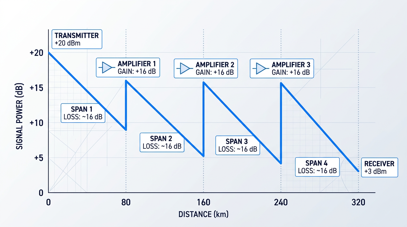
Along a fibre route, in-line amplifiers are positioned between the transmitter and receiver at intervals matched to the fibre's loss rate. Each amplifier is placed at the point where accumulated span loss has reduced the signal to a level that still permits clean amplification.
The amplifier restores the signal power, and the next fibre span begins — a repeating gain-loss cycle that extends the link's reach far beyond what any single loss budget could allow.
The technology that makes all-optical amplification practical at 1550 nm is the erbium-doped fibre amplifier (EDFA) — and understanding how it achieves gain inside the optical domain is the focus of the next section.
How EDFA Technology Enables All-Optical Amplification
The dominant amplification technology in global fibre networks is built around a single rare-earth ion — erbium (Er³⁺) — whose atomic physics, when expressed inside a silica fibre host, happens to produce optical gain precisely where silica fibre loses light least. That alignment is not a convenient engineering workaround; it is the physical foundation that made the erbium-doped fibre amplifier (EDFA) the technology of record for long-haul optical transmission.
An EDFA is built from four core components: a short length of silica optical fibre whose core is doped with trivalent erbium ions; a pump laser diode; a wavelength-division multiplexing (WDM) coupler that combines the pump light and the signal onto a single fibre path; and optical isolators at each end that block back-reflections from destabilising the amplifier.
Crucially, the gain medium is a piece of fibre — not a bulk crystal or a semiconductor chip — which is one reason the EDFA integrates so naturally into fibre transmission systems.
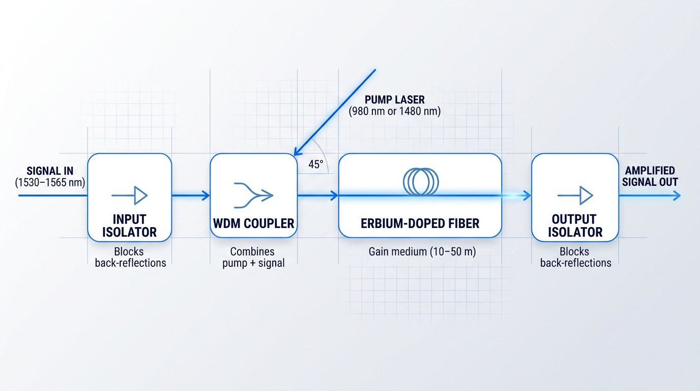
The amplification process begins with optical pumping: the pump laser, operating at either 980 nm or 1480 nm, delivers photons that excite erbium ions from their ground state into a higher energy level. When enough ions are elevated, the system reaches population inversion — a condition where more ions occupy the excited state than the ground state. Both pump wavelengths are used in practice and each carries distinct engineering consequences, covered in detail later in this guide.
Population inversion is the prerequisite for gain: without it, the erbium fibre would absorb the signal rather than amplify it. Once inversion is established, stimulated emission takes over.
When a signal photon in the 1530–1565 nm C-band passes through the population-inverted erbium fibre, it can trigger an excited ion to emit a second photon at exactly the same wavelength, phase, and direction. One photon becomes two — coherent, same-wavelength amplification, entirely within the optical domain, with no electrical conversion and no dependence on the signal's modulation format or data rate.
Why Erbium? The Physics Behind the C-Band Fit
The Er³⁺ gain band in silica spans the C-band (1530–1565 nm) and extends into the L-band (1565–1625 nm). This is almost exactly the window where silica optical fibre exhibits its lowest attenuation — the same preferred transmission window established by the physics of the glass itself.
The significance is hard to overstate: erbium's atomic energy levels, as they manifest inside a silica host, happen to produce stimulated emission precisely where the transmission medium loses least. This physical coincidence is what made the EDFA the dominant technology — not just a convenient option, but the right answer from first principles.
A second physical property of erbium reinforces its suitability for multi-channel networks. The erbium metastable state — the excited level from which stimulated emission occurs — has an unusually long lifetime, on the order of milliseconds. Because this lifetime is far longer than the bit period of any practical data signal, the erbium ions cannot respond fast enough to the instantaneous power fluctuations of individual bits or channels.
The practical consequence is significant: the gain does not fluctuate with any single channel's power, which means multiple WDM channels can be amplified simultaneously without inducing cross-talk between them. This is not a minor convenience — it is the property that makes the EDFA viable for dense wavelength-division multiplexed systems carrying dozens or hundreds of channels on a single fibre.
- Small-signal gain: 20–40 dB: A factor of 100 to 10,000 in optical power — sufficient to compensate for the loss of a typical fibre span between amplifier sites.
- Noise figure: 3–6 dB: Approaching the quantum-mechanical minimum of 3 dB for an ideal amplifier; a well-designed EDFA comes close to this fundamental limit.
- Gain bandwidth: C-band and L-band: Broad enough to amplify many WDM channels simultaneously across the 1530–1625 nm window in a single pass through the doped fibre.
The noise figure deserves particular attention: 3 dB is the absolute floor set by quantum mechanics for any phase-insensitive linear amplifier, and a well-engineered EDFA operates within a few decibels of that limit. In a cascade of many in-line amplifiers, even small differences in noise figure accumulate — which is why noise figure is one of the most consequential parameters in link design.
Because the EDFA operates entirely in the optical domain, it is transparent to data rate and modulation format. A 10 Gbit/s signal and a 400 Gbit/s signal are indistinguishable to the erbium ions — both are simply photons near 1550 nm. This means a network operator can upgrade terminal equipment, shift to higher-order modulation formats, or increase per-channel data rates without touching the in-line amplifiers, an advantage that optoelectronic repeaters — which had to be replaced with every data-rate generation — could never offer.
The EDFA's gain spectrum is not flat across the C-band — there is a pronounced peak near 1530 nm and a flatter region from roughly 1540–1560 nm. In a single amplifier this imbalance is manageable, but across a cascade of many in-line stages it accumulates: channels at the gain peak are progressively over-amplified relative to others. Gain-flattening filters (GFFs) are the standard engineering response, equalising the gain spectrum across the band. This is a well-understood challenge with a well-understood solution — not a fundamental limitation of EDFA technology.
Managing gain non-uniformity across a cascade is one part of a broader set of EDFA design choices that must be matched to the specific link — and this is where the gap between a catalogue amplifier and an application-engineered one becomes consequential. Operating band, output power, noise figure, pulse regime, cooling, and control firmware all interact with the link design; selecting them independently of the application leaves performance on the table.
Woodrow Scientific Limited's Custom EDFA is a concrete example of what application-engineered looks like in practice. The platform is configurable across C-band, L-band, or dual C+L — delivered through a single cable from one source — and is engineered end-to-end to the application: operating band, output power, pulse regime, cooling (air or water), form factor, and control firmware are all specified per project. Output power scales to the leading commercially available levels for erbium fibre, with average powers above 100 W, pulse energies above 10 mJ, and peak powers above 100 kW. WSL designs, builds, qualifies, and supports every amplifier in-house — not as a reseller — on patented technology, with fibre-amplifier expertise rooted in Southampton's Optoelectronics Research Centre, the institution where the EDFA was originally developed. Many suppliers in this market are resellers or importers, which limits their engineering depth and their ability to support or adapt the product; WSL's in-house model is a meaningful differentiator for demanding applications. The platform is CE and UKCA certified, operates at the eye-safe 1550 nm wavelength, and includes direct engineering support throughout integration.
With a firm grasp of how the EDFA produces gain — and what its key parameters mean — the natural next question is how the same underlying technology must be configured differently depending on where in the link it sits. That is the subject of the next section, which examines the distinct roles of in-line, booster, and pre-amplifier stages.
In-Line, Booster, and Pre-Amplifier: Three Roles in a Fibre Link
Most technical discussions treat optical amplifiers as a single category of device — something you place in a fibre link to restore signal level. That framing is not wrong, but it obscures a critical engineering reality: in any point-to-point fibre link, amplifiers occupy three distinct positions, and each position demands something different from the amplifier that fills it.
The three roles are the booster amplifier (sometimes called a power amplifier), the in-line amplifier (sometimes called a line amplifier), and the pre-amplifier. All three can be built on the same underlying EDFA technology, but the position each occupies in the link determines what it must optimise for — and those optimisation targets are not the same.
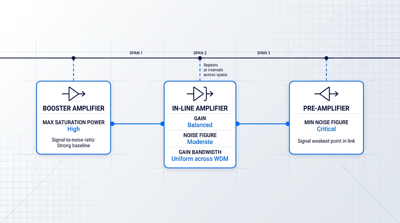
The schematic above captures the positional logic at a glance: each role has a fixed address in the link, and that address is what shapes its engineering brief.
- Booster amplifier: Sits immediately after the transmitter, before the first span. Primary requirement: high output (saturation) power to maximise launch power into the fibre.
- In-line amplifier: Placed at intervals between spans to compensate for accumulated span loss. Must balance gain, noise figure, and gain bandwidth across WDM channels simultaneously.
- Pre-amplifier: Positioned immediately before the receiver. Primary requirement: minimum noise figure, as the arriving signal is at its weakest point in the entire link.
The reason these requirements diverge comes down to signal strength and where noise matters most.
At the transmit end, the signal entering the booster is strong — it has not yet traversed any fibre loss — so the signal-to-noise ratio starts from a high baseline. A booster optimised for maximum saturation power will typically carry a higher noise figure, and that trade-off is acceptable here: the booster's noise contribution is small relative to the total link noise budget, and the priority is launching the strongest practical signal into the first span.
At the receive end, the same logic inverts entirely. The signal arriving at the pre-amplifier has traversed the full transmission distance and is at its weakest point in the link. Any noise added by the pre-amplifier at this stage degrades receiver sensitivity directly, with no subsequent span loss to dilute its relative impact. A pre-amplifier optimised for minimum noise figure may not deliver the saturation power a booster requires — but it does not need to, because its only job is to raise the signal to a level the detector can process reliably.
The in-line amplifier sits between these two extremes, and its engineering brief is the most demanding of the three as a result. It must provide enough gain to offset the loss of the preceding span, maintain a noise figure low enough to protect signal quality as noise accumulates across the cascade, and deliver sufficiently uniform gain across the WDM channel bandwidth to serve multiple wavelength channels simultaneously.
None of those three requirements can be relaxed without consequence — which is precisely what makes the in-line role distinct from both its neighbours in the link.
In practice, particularly in high-capacity DWDM long-haul and submarine systems, the boundaries between roles are not always sharp. Modern system designs increasingly push all three amplifier types toward low noise figure, high output power, and flat gain spectrum simultaneously, as capacity demands leave little margin anywhere in the link. The performance requirements are converging upward.
Even so, the placement-driven framework remains a sound and widely used engineering tool. Where requirements overlap, the primary optimisation target for each role is still distinct, and specifying an amplifier against the requirements of its intended position produces a better-matched result than selecting a generic part and hoping it performs adequately across all three.
An amplifier's position in the link is the primary design input. Choosing an amplifier without first resolving its role — and the gain, noise figure, saturation power, and bandwidth that role demands — is an engineering error that no amount of post-installation tuning can fully correct.
With the three roles established, the next question is what happens to signal quality as in-line amplifiers are cascaded across a long link — and why noise figure is not just a specification number but the primary constraint on how far a signal can travel.
Noise, ASE, and OSNR: Why Amplification Has a Cost
Every in-line amplifier in a fibre link does exactly what it is designed to do: it restores the signal power lost across the preceding span. But gain is never free — each amplifier that adds signal power also adds noise, and in a cascade of many amplifiers, that noise accumulates in a way that ultimately sets a harder limit on reach than attenuation ever could.
The noise mechanism is amplified spontaneous emission (ASE). Inside the population-inverted gain medium, excited erbium ions can decay spontaneously — without being triggered by an incoming signal photon — releasing photons at random phase, direction, and polarisation across the gain bandwidth. Those spontaneous-emission photons are then themselves amplified by the remaining gain medium, producing a broadband noise floor that propagates through the fibre alongside the signal.
ASE is not a manufacturing defect. It is a quantum-mechanical consequence of the same population inversion that makes gain possible in the first place — which means it cannot be eliminated, only managed.
In a cascade, the problem compounds. Each in-line amplifier adds its own ASE contribution, but critically, the ASE generated by every upstream amplifier is itself amplified by every downstream stage. The noise from the first amplifier in a chain is boosted by the second, the third, the fourth, and so on. Total accumulated noise power grows with the number of stages — making cascade length a fundamental engineering constraint, not merely a cost consideration.
Noise figure (NF) is the standard parameter engineers use to quantify how much an individual amplifier degrades the signal-to-noise ratio. The theoretical minimum for an ideal EDFA is 3 dB — the quantum noise limit. Practical devices typically achieve 4–6 dB. In a cascade of many stages, the difference between a 4 dB and a 6 dB NF amplifier compounds significantly: what looks like a modest per-stage difference accumulates into a substantial end-to-end performance gap. This is why noise figure is a primary specification for in-line amplifier selection, not a secondary one.
Optical signal-to-noise ratio (OSNR) is the system-level metric that captures the cumulative effect of all this noise. Defined as the ratio of signal power to accumulated ASE noise power — measured within a reference optical bandwidth — OSNR is the single number that determines whether a receiver can correctly recover the transmitted data. It is not a per-amplifier quantity; it reflects the total noise contribution from every stage the signal has passed through.
The mechanism of OSNR degradation along a cascade is straightforward but consequential. Each amplifier restores the signal power to approximately its pre-span level, but it adds its own ASE on top of the noise already present from all upstream stages. Signal power is restored; noise is not — it accumulates. OSNR therefore falls progressively along the route, and the receiver at the far end of a long chain sees a substantially lower OSNR than one at the end of a short link.
In a cascaded amplifier chain, OSNR degradation — not signal power loss — is the fundamental constraint that determines how far a signal can travel. Attenuation is solved at every span; accumulated ASE noise is not.
Every receiver and every modulation format has a minimum OSNR threshold below which the bit error rate (BER) becomes unacceptable — even with forward error correction (FEC) applied. Higher-order modulation formats such as 16-QAM demand considerably higher OSNR than simpler formats like BPSK or QPSK, because they pack more bits per symbol and are therefore more sensitive to noise. When accumulated ASE degrades OSNR below the required threshold, the link fails — not because the signal is too weak, but because the noise is too high.
System designers have four principal levers for managing OSNR across a cascade.
- Higher launch power: Raises the signal-to-noise ratio at each amplifier input. Constrained by nonlinear optical effects and amplifier saturation — there is an optimal level, not simply "more is better."
- Lower amplifier noise figure: Reduces ASE added per stage. The most direct lever available, and the primary reason NF is a first-order specification in cascade design.
- Shorter amplifier spacing: Reduces the gain each amplifier must deliver, which lowers ASE per stage. Achieved at the cost of more amplifiers and greater infrastructure investment.
- Forward error correction (FEC): Extends the usable OSNR range at the system level by allowing the receiver to correct errors up to a coding-gain limit, effectively lowering the minimum required OSNR.
These levers do not operate independently. Increasing launch power to improve OSNR pushes against nonlinear thresholds; shortening span spacing improves noise performance but changes the gain budget each amplifier must meet. Optimising any one parameter shifts the constraints on the others, which is why amplifier specification is a system-level decision rather than a component-selection exercise.
Selecting an in-line amplifier without accounting for its noise figure in the context of the cascade it will operate in is an engineering error that propagates through every stage downstream. A seemingly small NF difference per amplifier compounds across tens of stages into a significant reduction in end-to-end OSNR — one that can push a link below its BER threshold and render it inoperable at its intended data rate and reach. With the noise physics established, the next question is how engineers translate these constraints into concrete span design decisions.
Custom EDFAs Engineered for Your Application
Noise figure and gain performance are only as good as the EDFA behind them. Explore tailored EDFA solutions designed for demanding optical communications requirements.
Amplifier Spacing, Gain-Loss Balance, and Engineering Trade-offs
Physics tells you that signal power falls with every kilometre of fibre. Engineering tells you what to do about it — and the answer is more constrained than it first appears.
The Gain-Loss Balance: A Hard Operating Constraint
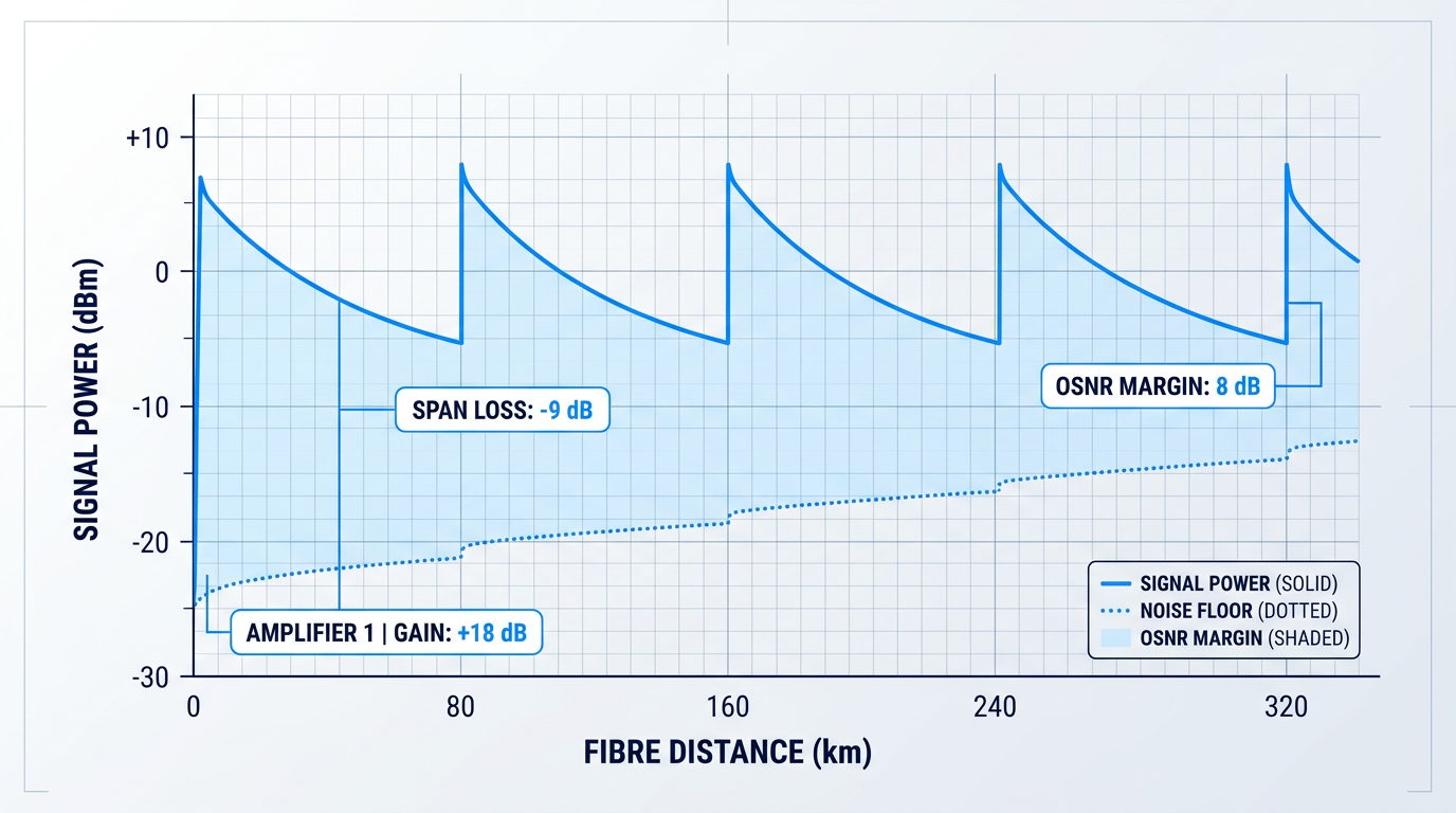
The foundational rule of span design is straightforward: each in-line amplifier's gain must approximately equal the loss of the preceding fibre span.
Standard single-mode fibre attenuates light at roughly 0.20 dB/km at 1550 nm, so an 80 km terrestrial span accumulates approximately 16–20 dB of loss — and the in-line amplifier at the end of that span must deliver 16–20 dB of gain to restore signal power to its pre-span level.
This is not a design aspiration; it is the operating constraint that defines the gain specification of every in-line amplifier in the link.
Typical Amplifier Spacing in Deployed Systems
In terrestrial long-haul networks, amplifier spacing is typically around 80 km — a figure driven directly by the loss budget at standard fibre attenuation rates.
Submarine systems operate under a different calculus: spans are typically compressed to 40–50 km because transoceanic links span thousands of kilometres through dozens of amplifier stages, and the cumulative OSNR penalty of higher per-stage gain makes shorter, lower-gain spans the preferred strategy for preserving signal quality at the far end.
The Central Trade-off: OSNR Versus Cost
Span length is the lever that controls both signal quality and infrastructure cost — and it pulls them in opposite directions.
- Shorter spans, lower gain: Each amplifier contributes less ASE accumulation per stage, preserving OSNR over the full link length — but more amplifier sites mean higher capital and maintenance cost.
- Longer spans, lower cost: Fewer amplifier sites reduce infrastructure expenditure, but each amplifier must deliver higher gain, increasing per-stage ASE and degrading OSNR across the chain.
There is no universally correct answer: the right spacing depends on the link's total length, the available OSNR budget, the physical infrastructure along the route, and the capital cost envelope the operator is working within.
In theory, the optimal strategy would be perfectly distributed gain — continuous amplification along the fibre that eliminates discrete noise-adding stages entirely. Raman amplification approaches this ideal by using the transmission fibre itself as the gain medium, but practical in-line EDFA deployment always forces a compromise between the theoretical noise minimum and the economic realities of real infrastructure.
Dispersion Management and Two-Stage Amplifier Architecture
At high bit rates, chromatic dispersion accumulates alongside attenuation and must be compensated at or near each amplifier site — making dispersion management an unavoidable co-located concern in span design.
Dispersion-compensating modules (DCMs) are passive, lossy components typically inserted into the mid-stage access point of two-stage in-line amplifiers: the amplifier is split into a first gain stage, the DCM, and then a second gain stage that overcomes the insertion loss the DCM introduces.
This is a practical reason why real in-line amplifiers in high-speed systems are so often two-stage designs — the mid-stage loss imposed by the DCM is a parameter that must be explicitly accounted for in the amplifier specification, not treated as an afterthought.
Launch Power and the Nonlinear Ceiling
Each amplifier must launch enough power into the next span to ensure the signal arrives at the following amplifier with sufficient strength to meet the OSNR requirement — but launch power is not a free variable.
Excessive launch power drives nonlinear effects in the fibre: self-phase modulation (SPM), cross-phase modulation (XPM), and four-wave mixing (FWM) all distort the signal and degrade transmission quality in ways that cannot be undone by subsequent amplification.
Launch power is bounded below by the OSNR requirement at the next amplifier input, and above by the onset of nonlinear penalties in the fibre. Every in-line amplifier must be specified to hit this window reliably — too little power degrades OSNR; too much corrupts the signal through nonlinearity.
Hitting this window consistently across every span in the link — accounting for span-to-span variation in fibre loss, connector aging, and temperature — is one of the practical demands that makes amplifier output power stability a critical specification parameter.
Span Design as System-Level Optimisation
The lesson of span design is that no single parameter can be optimised in isolation: amplifier spacing, gain, noise figure, launch power, and nonlinear tolerance all interact, and tightening one constraint typically relaxes or tightens another.
An in-line amplifier selected without reference to the specific link it will serve — its total length, span loss profile, target OSNR, and nonlinear budget — will rarely deliver the best result, regardless of its headline specifications.
With the link-level engineering constraints understood, the next dimension is how in-line amplifiers serve not one signal but dozens or hundreds of simultaneous wavelength channels in WDM systems — where these same trade-offs play out at network scale.
WDM Systems and the In-Line Amplifier's Network Role
What happens when a single fibre needs to carry not one data stream but a hundred? The answer to that question is what transformed the in-line EDFA from a useful component into the backbone of global data transmission.
Wavelength-division multiplexing (WDM) is the technique of combining multiple optical signals, each on a distinct wavelength, onto a single fibre — each wavelength acting as an independent data channel, multiplying the fibre's information-carrying capacity without laying new physical infrastructure.
The C-Band and L-Band: WDM's Spectral Real Estate
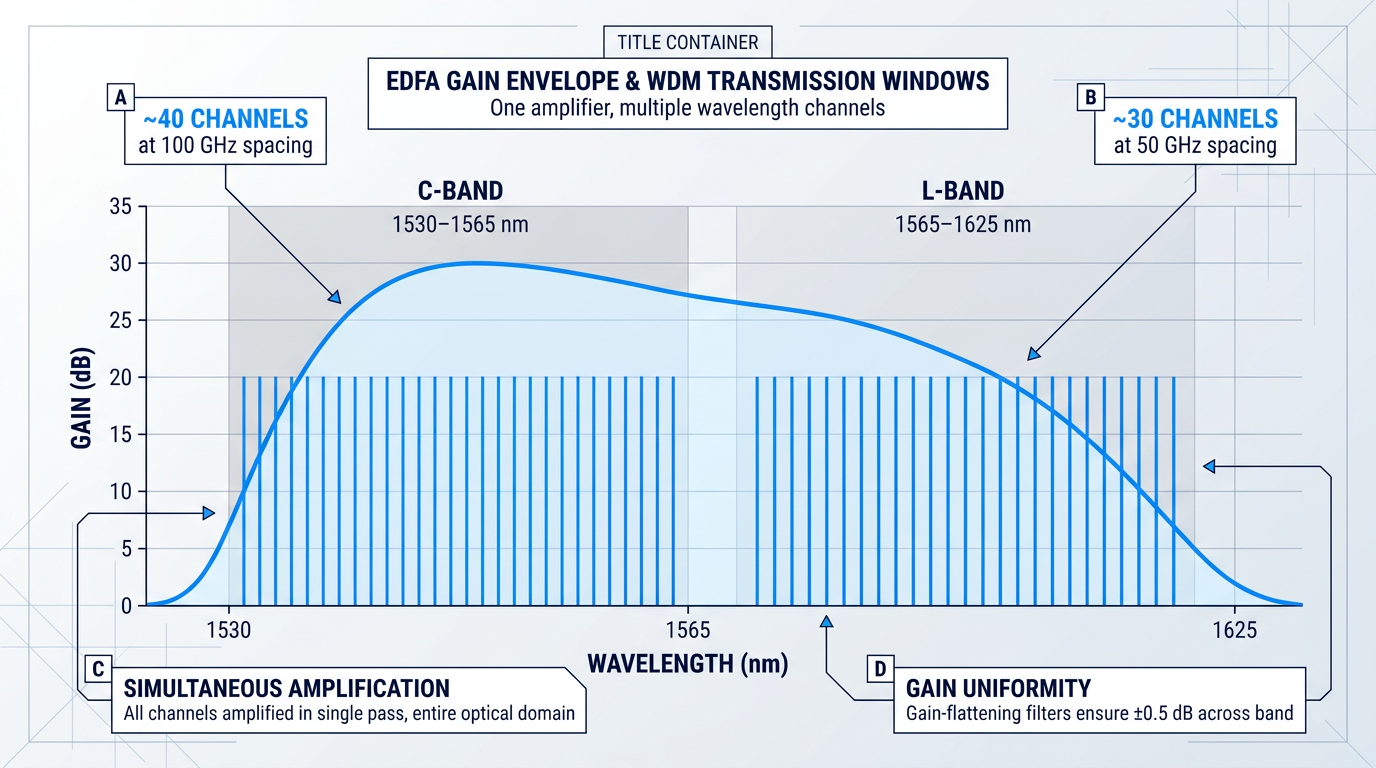
The C-band (1530–1565 nm) is the conventional WDM transmission window, and its dominance is not arbitrary: it coincides with both the lowest attenuation region of standard silica single-mode fibre and the natural gain band of erbium-doped fibre amplifiers.
The L-band (1565–1625 nm) extends usable capacity further, exploiting the same erbium gain medium under adjusted pumping conditions to open an additional transmission window when C-band capacity is exhausted.
Together, the C- and L-bands define the spectral real estate that WDM systems exploit — and the EDFA's gain envelope spans both, which is precisely why it became the dominant amplification technology for long-haul transmission.
One Amplifier, Every Channel Simultaneously
The EDFA's defining capability in a WDM context is straightforward but consequential: a single amplifier simultaneously amplifies all WDM channels whose wavelengths fall within its gain window, in a single pass, entirely within the optical domain.
A conventional C-band EDFA with a 30 nm amplification bandwidth can amplify up to approximately 40 DWDM channels at 100 GHz channel spacing — and that number grows as channel spacing narrows or the L-band is added.
The practical consequence is decisive: one amplifier per span site, regardless of how many wavelength channels are active on the fibre.
Replacing the Bank of Optoelectronic Repeaters
Before EDFAs, multi-wavelength transmission over long distances required one optoelectronic repeater per wavelength channel at every regeneration site: each repeater detected the optical signal electrically, processed it, and re-transmitted it — a separate piece of hardware for every channel at every site along the route.
As IEEE TechNav notes, before the EDFA, each regeneration site required optical-to-electrical conversion, reshaping, and retransmission for every channel, making multi-channel systems impractical at long distances.
The EDFA replaced the entire bank of per-channel repeaters with a single optical amplifier — a transformation that reduced infrastructure complexity at every intermediate site from N pieces of hardware to one.
Once fibre spans and in-line amplifiers are installed, additional WDM channels are activated by provisioning new transmitters and receivers at the terminal endpoints only — the in-line amplifiers require no modification. Capacity grows at the terminals, not along the route.
This pay-as-you-grow property is significant: the installed amplifier infrastructure is not a constraint on capacity growth, and each incremental channel added to the system requires no revisiting of the amplifier hardware along the fibre route.
Lightwave Online captured the economic logic directly: WDM is cost-effective because the cost of amplifiers can be spread across many WDM channels, and after optical amplifiers enabled WDM, the cost to light a channel became a fraction of what it was before.
Gain Flatness: The WDM Engineering Challenge
Deploying EDFAs in WDM systems introduces a direct engineering consequence: the erbium gain spectrum is not uniform across its bandwidth, so channels at different wavelengths receive different amounts of amplification.
In a cascade of many in-line amplifiers, this imbalance compounds with each stage — channels at high-gain wavelengths accumulate excess power while channels at low-gain wavelengths are progressively under-amplified, creating significant power disparities across the channel plan that degrade the OSNR budget established earlier in the link.
Gain-flattening filters (GFFs) are used at or within amplifier stages to equalise the gain spectrum, transmitting more light at wavelengths where EDFA gain is lower and attenuating where it peaks — ensuring all channels arrive at the receiver with comparable signal quality.
Passive GFFs inserted in the middle stage of a dual-stage amplifier have demonstrated spectral gain uniformity within 0.5 dB across the C- and L-bands — a well-understood engineering solution to a well-understood engineering problem.
DWDM Channel Grids and the ITU-T Standard
Dense WDM (DWDM) systems pack channels into the C-band at standardised spacings defined by ITU-T G.694.1, the international standard governing the DWDM frequency grid.
ITU-T G.694.1 defines fixed channel spacings of 12.5, 25, 50, and 100 GHz, all anchored to a reference frequency of 193.1 THz — with approximately 40 channels fitting the C-band at 100 GHz spacing, doubling to around 80 at 50 GHz, and increasing further as spacing narrows.
For in-line amplifiers operating within a DWDM system, the gain flatness requirement is not a design preference — it is a system-level necessity: the amplifier must deliver sufficiently uniform gain across the entire channel plan defined by the ITU-T G.694.1 grid for the system to function correctly.
In-line EDFA technology is not a component detail — it is the enabling capability that made transoceanic data links carrying terabits per second technically and economically viable, and it remains central to every high-capacity long-haul and submarine fibre network deployed today.
With WDM in view, the full picture of what in-line amplifiers do and why they matter is now complete — the Conclusion draws together the arc from signal attenuation through to the network infrastructure that carries the world's data.
Conclusion
What In-Line Amplifiers Do and Why They Matter
Erbium won because physics gave it no competition: its gain band sits precisely where silica fibre loses the least light, making the in-line EDFA not just a good solution to signal attenuation but the natural one.
What that means in practice is that every amplifier in a chain is a system-level commitment, not a component choice — noise figures, span lengths, and OSNR budgets are the variables that determine whether a link actually works at distance.
Paired with WDM, that capability scaled into the physical infrastructure carrying the world's data traffic, which is what makes understanding it worth the effort.
Frequently Asked Questions About In-Line Optical Fibre Amplifiers
Technical clarifications on optical amplifier types, EDFA pump physics, gain flattening, dispersion compensation, and the distinction between in-line amplifiers and regenerators.
The three principal types are erbium-doped fibre amplifiers (EDFAs), Raman amplifiers, and semiconductor optical amplifiers (SOAs). EDFAs dominate long-haul in-line applications because of their low noise figure, broad gain bandwidth across the C-band and L-band, transparency to data rate and modulation format, and decades of deployment maturity. Raman amplifiers exploit stimulated Raman scattering in the transmission fibre itself, producing distributed gain rather than lumped gain at a discrete component. This distributed amplification reduces average signal power in the fibre, which lowers nonlinear impairments and improves OSNR over very long spans. Raman amplifiers are widely used in combination with EDFAs in ultra-long-haul and submarine systems, and require high pump power — typically in excess of 500 mW for distributed configurations. SOAs use stimulated emission in a forward-biased semiconductor junction. They are compact and integrable with photonic circuits, but carry a higher noise figure and greater polarisation sensitivity than EDFAs. Their fast gain dynamics make them useful for optical switching and wavelength conversion, but problematic for WDM multichannel amplification without careful engineering. EDFAs remain the technology of choice for in-line amplification: low noise, broad flat gain, format transparency, and a mature global supply chain are advantages no competing technology currently matches across the full range of long-haul applications.
An in-line amplifier boosts the optical signal entirely within the optical domain, with no electrical conversion. A regenerator (or optoelectronic repeater) performs optical-electrical-optical (OEO) conversion: the signal is detected, converted to an electrical signal, then re-shaped, re-timed, and re-transmitted as a fresh optical signal. This is known as 3R regeneration — re-amplify, re-shape, re-time. The key trade-off is format transparency versus signal cleanliness. A regenerator eliminates accumulated noise and dispersion distortions at each site, producing a clean slate — but it is data-rate and modulation-format specific, so upgrading the system requires replacing the regenerators. An in-line amplifier, by contrast, is transparent to data rate and modulation format: the same unit can serve a 10 Gbit/s system today and a 400 Gbit/s system tomorrow without hardware replacement. The cost is that accumulated ASE noise and dispersion distortions are not corrected — they build up across the cascade. In modern long-haul networks, in-line amplifiers have largely replaced regenerators because the economics strongly favour format-transparent amplification, with dispersion managed separately using optical compensation modules.
The choice between 980 nm and 1480 nm pump wavelengths involves a direct trade-off between noise figure and output power. A 980 nm pump achieves a lower noise figure — closer to the theoretical 3 dB quantum limit — making it the preferred choice where minimising noise is the priority. A 1480 nm pump delivers higher output power for a given pump power budget, making it better suited to configurations where maximising launched signal power matters more than noise. The physics behind this split: 980 nm pumping excites erbium ions to a higher energy level from which they rapidly decay to the metastable upper lasing level, achieving a higher degree of population inversion and therefore a lower noise figure. The 1480 nm pump excites ions directly into the lower edge of that upper lasing level, producing less complete inversion and a slightly higher noise figure — but because a 1480 nm photon carries less energy than a 980 nm photon, more pump photons are available per milliwatt of pump power, making 1480 nm more efficient for high output power. In practice, many in-line amplifiers use both wavelengths simultaneously. A common configuration co-pumps the first stage with a 980 nm laser (for low noise) and counter-pumps the second stage with a 1480 nm laser (for high output power), optimising both parameters in a single two-stage design.
Gain flattening is the process of equalising an EDFA's gain across its operating wavelength band so that all WDM channels receive comparable amplification. It matters because an untreated EDFA does not amplify all wavelengths equally: the gain spectrum is non-uniform, with a pronounced peak near 1530 nm and a flatter region between roughly 1540 and 1560 nm. In a single amplifier, this imbalance is modest. Across a cascade of many in-line amplifiers — as in any long-haul link — the imbalance compounds at every stage. Channels sitting at the gain peak receive progressively more amplification than channels in the flatter region, and the power difference between the strongest and weakest WDM channels grows with each amplifier traversed. The consequences are significant: over-amplified channels risk saturating the amplifier and generating excess ASE noise, while under-amplified channels arrive at the receiver with insufficient OSNR. Either outcome degrades link performance. Gain-flattening filters (GFFs) address this by presenting a transmission profile that is the inverse of the EDFA gain spectrum — attenuating the high-gain wavelengths and passing the lower-gain wavelengths so that the net gain across the band is equalised. GFFs are typically placed at the output of each EDFA or in the mid-stage of a two-stage amplifier. With gain flattening applied at each amplifier site, all WDM channels accumulate comparable OSNR across the cascade — a prerequisite for reliable multi-channel transmission over long distances.
No. In-line amplifiers restore signal power but have no mechanism to correct chromatic dispersion or other signal distortions. EDFA amplification is a photon-multiplication process: it adds coherent photons at the signal wavelength via stimulated emission, restoring optical power. It cannot reverse the temporal spreading of pulse components that travel at slightly different speeds through the fibre — a phase-domain distortion that amplification does not touch. Dispersion compensation requires separate optical elements. The most widely deployed solution is dispersion-compensating fibre (DCF), a specially designed fibre with a large negative dispersion coefficient that cancels the positive dispersion accumulated in standard single-mode fibre. An alternative is chirped fibre Bragg gratings (FBGs), which introduce a frequency-dependent group delay that recompresses dispersed pulses; FBG-based modules offer lower insertion loss than DCF and a smaller physical footprint. In high-bit-rate long-haul links, dispersion-compensating modules (DCMs) are typically placed in the mid-stage of a two-stage in-line amplifier — between the first amplifier stage, which brings the signal to a workable power level, and the second stage, which overcomes the insertion loss of the DCM and launches the required power into the next span. In modern coherent systems, digital signal processing (DSP) in the coherent receiver can compensate for chromatic dispersion electronically, reducing the need for in-line optical dispersion compensation — though optical compensation retains advantages in certain long-haul and mixed-traffic scenarios.