

Introduction
If you're here, you already know the basics — and you're looking for something more useful than a spec sheet or a physics lecture.
This guide is written for engineers, system designers, and technically literate buyers who need to understand high power fiber lasers at a level that actually informs decisions: how the technology works, how it scales, and — critically — what limits that scaling.
The coverage builds from foundational architecture through to the thermal and optical constraints that define real-world performance, then out to the industrial, scientific, and defence domains where these systems are deployed.
The place to start is the question that underpins everything else: what actually makes a fibre laser capable of operating at high power in the first place.
TL;DR
Raw output power is rarely the binding constraint in a high-power fibre laser system. Beam quality, thermal architecture, and nonlinear optical limits are what determine whether a system can actually do the job — and they interact in ways that most available content, from OEM datasheets to academic papers, either glosses over or isolates from each other.
This article covers:

Double-clad fibre architecture and brightness conversion fundamentals
Power scaling: single-mode sources to multi-kilowatt systems
Single-emitter, MOPA, and beam-combining architectures compared
Wavelength, mode, and beam quality metrics explained
Thermal limits, nonlinear effects, TMI, and photodarkening
Industrial, scientific, and defence application demands
What Are High Power Fiber Lasers?
High-power diode arrays are among the most cost-effective and electrically efficient light sources available — yet they produce beams so spatially incoherent that they are largely useless for precision material processing on their own. High-power fibre lasers solve this problem structurally: the optical fibre itself acts as a brightness converter, accepting that low-quality diode light and delivering near-diffraction-limited output at the other end.
At their core, high-power fibre lasers are optical fibres doped with rare-earth ions that serve as the gain medium, producing output power ranging from hundreds of watts to beyond 100 kW for industrial manufacturing, scientific research, and defence applications.
The Double-Clad Fibre Architecture
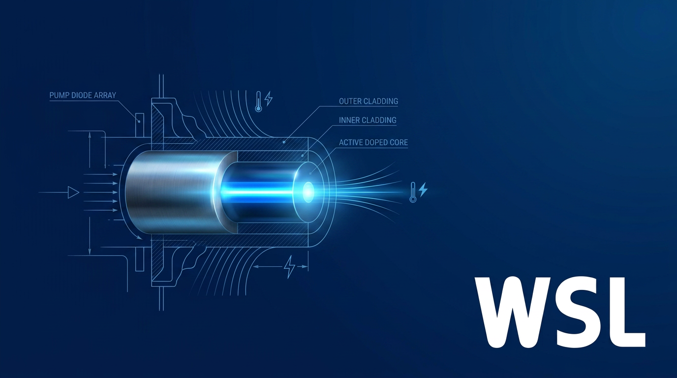
The enabling structural feature is the double-clad fibre: a rare-earth-doped single-mode core at the centre, surrounded by a much larger multimode inner cladding, which is itself enclosed by an outer cladding or polymer coating with a lower refractive index.
Pump light from multiple diode sources is coupled into the large inner cladding, where it propagates and is gradually absorbed by the small doped core — which amplifies the signal guided within it.
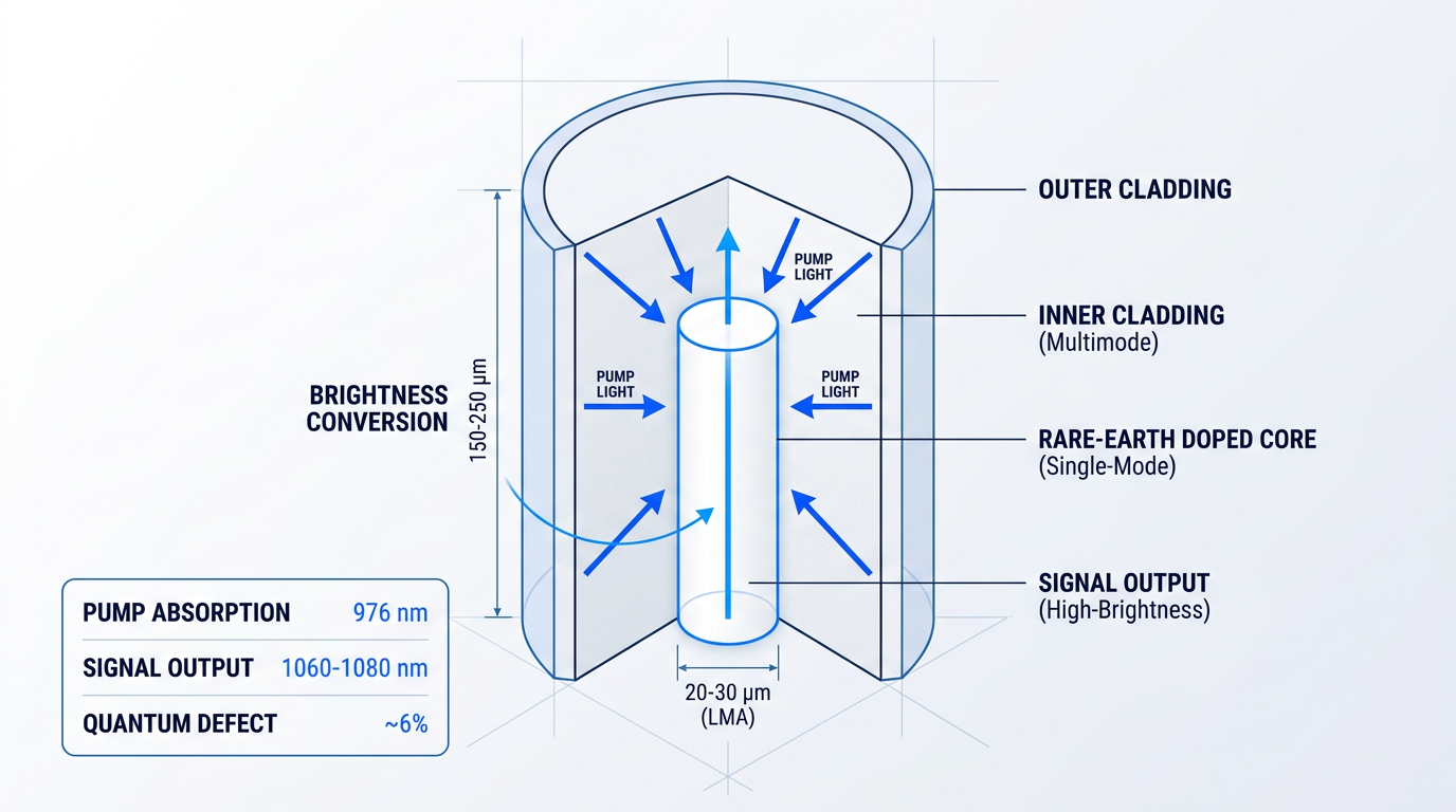
The consequence of this geometry is brightness conversion: the multimode, spatially incoherent pump radiation coupled into the inner cladding is absorbed and re-emitted by the rare-earth-doped core as high-brightness, near-diffraction-limited single-mode output.
Brightness conversion is the architectural trick at the heart of fibre lasers: low-brightness, incoherent diode pump light enters the inner cladding; high-brightness, near-diffraction-limited laser light exits the single-mode core — the fibre cavity performs the conversion structurally, regardless of pump beam quality.
The Two-Stage Industrial Fibre Laser
In a typical industrial system, Stage 1 is a power combiner: multiple single-emitter diode packages deliver their multimode pump outputs into a passive transmission fibre, aggregating raw pump power from many sources into a single waveguide.
Stage 2 is the brightness converter proper: an optical cavity defined by two fibre Bragg grating (FBG) mirrors converts that aggregated, low-quality pump light into a single-mode laser output with well-defined wavelength and beam characteristics.
Gain Dopants: Ytterbium and Beyond
Ytterbium (Yb) is the dominant gain dopant for high-power fibre lasers, offering output in the ~1060–1080 nm range (with gain bandwidth spanning ~1030–1100 nm), a pump absorption band centred near 976 nm, and optical-to-optical conversion efficiencies approaching 80%.
Yb's thermal advantage stems from its small quantum defect — approximately 6% when pumping at 975 nm with signal output near 1035 nm — meaning only a small fraction of each pump photon's energy is deposited as heat, which is a significant advantage for thermal management at high average powers.
The other principal rare-earth dopants each occupy distinct wavelength windows suited to specific applications, and are introduced briefly here for orientation.
- Erbium (Er): Output ~1500–1570 nm; the eye-safe telecom band, compatible with standard fibre communications infrastructure.
- Thulium (Tm): Output ~1900–2050 nm; eye-safer wavelength with strong absorption in water, suited to soft-tissue and atmospheric applications.
- Holmium (Ho): Output in the ~2 µm region; often co-doped with Tm for efficient energy transfer at this wavelength.
Each dopant's wavelength range, efficiency characteristics, and application suitability are examined in detail when wavelength and beam quality are discussed later in this guide.
The Fibre Geometry Thermal Advantage
The fibre form factor provides an inherent thermal advantage over bulk solid-state lasers: the high surface-area-to-volume ratio of a long, thin fibre allows waste heat to dissipate passively along its length rather than accumulating at a single gain element.
Critically, the waveguide structure maintains beam quality independently of thermal gradients and mechanical perturbations — in contrast to bulk solid-state lasers such as Nd:YAG, where thermal lensing progressively degrades beam quality as output power increases.
How High-Power Fibre Lasers Differ From Standard Fibre
High-power systems use large-mode-area (LMA) fibre with core diameters typically in the 20–30 µm range and reduced numerical aperture, compared to the ~8–10 µm cores of standard telecom single-mode fibre; the larger core reduces optical intensity inside the waveguide, raising the threshold at which nonlinear optical effects become problematic.
Compared to conventional bulk solid-state lasers, the all-fibre cavity eliminates the free-space optical components that require precise alignment and periodic maintenance — the waveguide-defined beam quality is a structural property of the system, not a parameter that needs tuning.
With the architectural foundations in place, the natural next question is how far this architecture can be pushed — and the answer, traced through decades of development and today's commercial landscape, spans a remarkable range of output power.
From Milliwatts to 100 kW and Beyond
Few technologies have climbed the power curve as rapidly as high-power fibre lasers. In roughly four decades, output from rare-earth-doped fibre sources has advanced from a few milliwatts — a laboratory novelty — to commercial systems delivering tens of kilowatts from a single aperture and beam-combined installations exceeding 100 kW. That trajectory is not slowing.
The Historical Arc: Milliwatts to Kilowatts
The earliest rare-earth-doped fibre lasers, demonstrated in the early 1960s, produced a few milliwatts and remained laboratory curiosities for decades.
The first genuine inflection point came in 1988, when Elias Snitzer and colleagues at Polaroid demonstrated the double-clad fibre laser — a design that separated the pump waveguide from the signal core, allowing low-brightness multimode diode light to pump a single-mode signal path efficiently.
This cladding-pumping breakthrough decoupled pump brightness requirements from output power for the first time, enabling the step from tens of milliwatts to watts and then, through the 1990s and 2000s, into the kilowatt regime as diode brightness and fibre fabrication quality improved in parallel.
Today, the commercial landscape spans from compact sub-watt rack-mount modules through single-aperture systems at 10 kW or more, with beam-combined installations demonstrated well above 100 kW in defence programmes — a span of more than seven orders of magnitude from the technology's origins.
The Commercial Power Tiers
The current market can be understood in three broad tiers, each reflecting a different balance of beam quality, raw power, and application context.
| Tier | Typical Power Range | Beam Character | Representative OEMs |
|---|---|---|---|
| Single-mode industrial | Up to 10 kW (single aperture) | Near-diffraction-limited (M² < 1.1–2 depending on power) | IPG Photonics (YLS-SM: up to 10 kW), Coherent (HighLight FL CSM: up to 2.5 kW SM), TRUMPF (TruFiber P: SM up to 2 kW) |
| Multimode industrial | 1 kW – 125+ kW | Higher BPP; larger spot at high power | IPG Photonics (YLS/YLR: 1–125+ kW), Coherent (HighLight FL: 1–10 kW), TRUMPF (TruFiber S/G: 3–12 kW), nLIGHT (CFL series: 500 W–15 kW) |
| Beam-combined (defence / directed energy) | 30 kW – 500 kW class (demonstrated) | Near-diffraction-limited via spectral or coherent combining | Lockheed Martin ATHENA (30 kW field-tested 2015; 58 kW delivered 2017); HELSI programme (300 kW, scaling to 500 kW class) |
Maps the three commercial power tiers of high-power fibre lasers with representative OEM names and vendor-sourced power ranges, enabling readers to orient quickly before evaluating architecture choices.
The single-mode tier is where beam quality is treated as non-negotiable: IPG Photonics' YLS-SM cabinet series, for instance, maintains M² below 1.1 up to 2 kW and below 1.2 up to 5 kW, with a rated ceiling of 10 kW from a single aperture.
Multimode systems accept a higher beam parameter product (BPP) in exchange for greater raw power — a trade that suits thick-plate cutting and heavy welding where a larger focused spot at high fluence is the requirement rather than a penalty.
The beam-combined tier sits outside the standard product catalogue entirely: these are programme-specific demonstrations, not off-the-shelf units. Lockheed Martin's spectral beam combining work — from the 30 kW ATHENA system field-tested in 2015 through the 58 kW delivery to the US Army in 2017 — illustrates how individual fibre channels are aggregated to reach power levels no single aperture can sustain.
LMA Fibre: The Engine of Power Scaling
The enabling technology that has allowed single-aperture power to climb is large-mode-area (LMA) fibre — and understanding its role clarifies why scaling is not simply a matter of pumping harder.
Standard telecom single-mode fibre carries a core diameter of roughly 6–8 µm. LMA fibres used in high-power systems expand this to typically 20–30 µm, with some rod-type designs reaching beyond that.
The larger core reduces optical intensity at a given power level, which raises the threshold at which nonlinear effects become problematic — the threshold for stimulated scattering processes scales with mode area divided by fibre length.
Preserving beam quality in a larger core requires careful waveguide engineering: core numerical aperture is reduced (typically to 0.06–0.08) so that the structure preferentially guides the fundamental mode while imposing higher loss on higher-order modes.
This is a constrained optimisation, not a free variable — core diameter, numerical aperture, and doping profile must be co-designed together, and there is a practical ceiling on how far the core can be enlarged before mode discrimination fails and other constraints take over.
Three Constraints on Single-Aperture Scaling
Despite the progress enabled by LMA fibre design, three physical constraints currently govern how far a single fibre aperture can be pushed — and they are the reason beam combining exists as a scaling strategy at all.
- Nonlinear optical effects: Stimulated Raman scattering (SRS) and stimulated Brillouin scattering (SBS) drain power from the signal into unwanted frequency-shifted waves; threshold scales with intensity and interaction length.
- Transverse mode instability (TMI): Above a threshold average power, thermally driven coupling transfers energy from the fundamental mode into higher-order modes, causing rapid beam quality degradation.
- Thermal load: Heat deposited in the gain fibre increases with output power; if not managed, it degrades waveguiding properties and risks physical damage to the fibre.
These three constraints are the subjects of dedicated sections later in this guide — nonlinear effects in §8, TMI and photodarkening in §9, and thermal management in §7. They are introduced here because they collectively define the practical ceiling on single-aperture power and explain why the commercial landscape has evolved the way it has.
Wall-Plug Efficiency: A Practical Differentiator
Beyond raw power, wall-plug efficiency — the ratio of optical output to electrical input — is one of the most consequential system-level metrics for high-power fibre lasers, particularly in continuous production environments.
High-power fibre lasers can reach wall-plug efficiencies of around 50% in the best cases, according to RP Photonics, with typical industrial Yb-fibre systems operating above 30%.
By comparison, lamp-pumped Nd:YAG lasers achieve wall-plug efficiencies of at most a few percent, and CO₂ lasers typically fall in the 10–20% range.
High-power Yb-fibre lasers can reach ~50% wall-plug efficiency. Lamp-pumped Nd:YAG systems manage at most a few percent. At multi-kilowatt power levels, that gap translates directly into operating cost, cooling infrastructure, and system footprint.
In a continuous production facility running multi-kilowatt lasers for thousands of hours per year, the difference between 10% and 40%+ efficiency is not a footnote on a spec sheet — it determines the size of the chiller plant, the electricity bill, and the thermal management burden on the surrounding system.
Power Is One Axis, Not the Primary One
The commercial power tiers and the efficiency advantage paint an impressive picture — but for most applications, raw output power is not the primary selection criterion.
A 10 kW system with degraded beam quality may be less capable for precision cutting than a 3 kW system delivering near-diffraction-limited output: the usable power at the workpiece depends on how tightly the beam can be focused, which is a function of beam quality and architecture, not wattage alone.
The power tier a system targets largely determines which architecture is appropriate — and each architecture involves distinct trade-offs in beam quality, linewidth, and system complexity that the next section unpacks in detail.
Fiber Laser Architectures: Single-Emitter, MOPA, and Beam Combining
The architecture decision is not a downstream detail — it is the foundational engineering choice that sets the beam quality ceiling, determines linewidth control capability, defines the scalability path, and fixes system complexity before a single component is specified.
Five architecture families span the practical design space for high power fiber lasers: the single-emitter fibre oscillator at the simplest end, the MOPA configuration that dominates commercial kilowatt-class systems, and three beam-combining approaches — incoherent beam combining (IBC), spectral beam combining (SBC), and coherent beam combining (CBC) — each representing a distinct position in the trade-off between raw power, beam quality, and engineering complexity.
Single-Emitter Fibre Oscillator: The Baseline Architecture
The single-emitter oscillator is the foundational architecture: an all-fibre cavity defined by two fibre Bragg gratings (FBGs) acting as cavity mirrors, diode-pumped through a double-clad fibre, producing continuous-wave (CW) output with no free-space optics and no moving parts.
Its principal virtues are simplicity, robustness, and compactness — the monolithic, alignment-free construction makes it the most reliable architecture available, well-suited to applications requiring moderate power without precise spectral control.
The power ceiling for a single-aperture oscillator is bounded at a few kilowatts: stimulated Raman scattering (SRS), stimulated Brillouin scattering (SBS), and transverse mode instability (TMI) become progressively limiting as power increases, with TMI typically manifesting above 1 kW in step-index fibre designs — the mechanics of each are covered in the challenge sections that follow.
MOPA: Decoupling Spectral Control from Power Scaling
The master oscillator power amplifier (MOPA) architecture separates the two engineering problems that a single oscillator must solve simultaneously: a low-power master oscillator establishes the wavelength, linewidth, and temporal character of the output, while one or more downstream fibre amplifier stages boost power without altering those properties.
This decoupling is the defining advantage at kilowatt scales — spectral and temporal parameters can be optimised independently of the power stage, enabling precise pulse shaping, narrow linewidth, and modulation capability that a single oscillator cannot provide at high power.
Three enabling components make MOPA practical at high power, each addressing a distinct engineering constraint at the interface between stages.
- Mode Field Adapters (MFAs): Match beam size from the small-core seed fibre to the large-mode-area (LMA) amplifier fibre, minimising insertion loss between stages.
- Pump/Signal Combiners: Inject multimode pump light from diode arrays into the amplifier cladding, enabling power scaling to kilowatt levels within an all-fibre format.
- End Caps: Expanded fibre end facets that reduce output power density to below the fibre damage threshold, preventing facet failure at high power.
MOPA configurations serve both CW and pulsed systems, including ultrafast chirped-pulse amplification (CPA) architectures, making it the dominant commercial architecture across the broadest range of high-power applications.
One constraint worth flagging here: narrow-linewidth MOPA systems are more sensitive to SBS than single-emitter oscillators, because the narrow linewidth required for precise spectral control also lowers the SBS threshold — a tension addressed directly in §8.
Beam Combining: Three Paths to Higher Power
When single-aperture power limits are reached, beam combining is the route forward — but the three principal approaches make fundamentally different trade-offs between output beam quality, phase control complexity, and the scalability of the combined system.
| Architecture | Beam Quality Preserved | Phase Control Required | Scalability Limit | Demonstrated Power / Beam Quality | Primary Applications |
|---|---|---|---|---|---|
| Incoherent Beam Combining (IBC) | No — M² degrades with channel count; BPP grows as √N × single-source BPP (evanescent fibre combining) | None | Effectively unlimited; power scales directly with channel count | Continuous outputs to 50 kW by mixing fibre-laser outputs in large-core multimode fibres | Thick-plate cutting and welding; solid-state laser pumping; incoherent frequency conversion |
| Spectral Beam Combining (SBC) | Near-diffraction-limited retained — M² ~1.35 at ~3 kW (12-channel Lockheed Martin SBC demonstration) | None — wavelength separation eliminates phase locking requirement | Bounded by gain bandwidth (~50 nm for Yb-doped silica); limits resolvable channel count | 30 kW weapons-grade (Lockheed Martin, multiple fibre modules); 30 kW-class HEL (nLIGHT SBC) | Directed energy; high-brightness precision industrial; applications needing near-DL output without phase control |
| Coherent Beam Combining (CBC) | Near-diffraction-limited retained — M² ≤ 1.2 at 10.4 kW (12-channel); M² ~1.06 at 5 kW (5-channel DOE) | Active phase locking required on every channel; phase sensors and feedback loops throughout | No gain-bandwidth ceiling; scales with channel count — nLIGHT demonstrated 300 kW-class CBC under HELSI | 1.45 kW (AFRL LOCSET, 16-channel 4×4 array); 5 kW (5-channel, 82% efficiency); 10.4 kW (12-channel); 70 kW-class (nLIGHT HADES CBC HEL) | Directed energy weapons; high-brightness scientific; ultrafast high-average-power systems |
Comparison of IBC, SBC, and CBC beam combining architectures across key engineering axes, populated with specific demonstrated data from research sources.
The table reveals the central pattern: beam quality is the axis that differentiates the three approaches, not raw power — IBC can reach the highest aggregate powers most simply, but only SBC and CBC preserve the near-diffraction-limited beam quality that high-brightness applications demand.
Incoherent beam combining is the most straightforward approach: multiple fibre outputs are spatially combined into a single multimode beam via a fibre bundle or combiner, with output power scaling in direct proportion to channel count.
The beam quality trade-off is fundamental and irrecoverable — because the individual channels are spatially incoherent, the beam parameter product (BPP) of the combined output grows approximately as the square root of the number of sources multiplied by the BPP of a single source; IBC is a path to high-power multimode output, not high-brightness output.
Spectral beam combining preserves near-diffraction-limited beam quality without requiring any phase control between channels: each fibre amplifier operates at a slightly different wavelength within the Yb gain bandwidth, and a multi-layer dielectric (MLD) diffraction grating recombines the wavelength-separated beams into a single co-propagating output.
The architectural ceiling is the gain bandwidth itself — with Yb-doped silica offering approximately 50 nm of usable bandwidth, the number of resolvable spectral channels is finite, bounding ultimate scalability; Lockheed Martin demonstrated a 30 kW weapons-grade SBC system, and nLIGHT's 30 kW-class SBC high-energy laser employs the same principle for directed-energy applications.
Coherent beam combining removes the gain-bandwidth ceiling entirely: all channels operate at the same wavelength, and active phase locking is required — the phase of each amplifier output is continuously measured and corrected so that all channels interfere constructively at the target, preserving beam quality and brightness in proportion to channel count.
Combining is achieved using a diffractive optical element (DOE) in tiled-aperture or filled-aperture configurations, with phase sensors and active feedback loops on every channel; AFRL's LOCSET (Locking of Optical Coherence by Single-detector Electronic-frequency Tagging) demonstrated coherent combination of 16 narrow-linewidth 90 W lasers in a 4×4 array to produce 1.45 kW — at the time, the highest output power recorded for a coherently combined fibre laser array.
CBC carries a specific tension with SBS: narrow linewidth is required for coherent combining, but narrow linewidth also lowers the SBS threshold; PRBS (pseudo-random binary sequence) phase modulation is the established technique for broadening linewidth sufficiently to suppress SBS while remaining compatible with CBC path-length matching — demonstrated at 1.17 kW per channel and extended to 5 kW total across five 1.2 kW channels at M² of 1.06.
SBC delivers near-diffraction-limited output at multi-ten-kilowatt levels without any phase control hardware — bounded by gain bandwidth (~50 nm for Yb). CBC removes that bandwidth ceiling entirely and scales brightness without limit in principle, but demands active phase locking on every channel and introduces a fundamental SBS-linewidth tension that must be actively managed on each amplifier.
Mapping application requirements to architecture is, in practice, a beam quality and linewidth decision first, with power as the secondary axis: single-emitter oscillators suit sub-kW to low-kW applications needing maximum simplicity; MOPA is the dominant choice at kilowatt scales wherever spectral or temporal control matters; IBC serves high-power multimode applications such as thick-plate processing where diffraction-limited output is not required; SBC is the right choice for near-diffraction-limited output without phase control complexity; and CBC is the route to maximum brightness at the highest power levels, with nLIGHT's CBC architecture having demonstrated 300 kW-class output under the DoD HELSI programme.
With the architecture landscape mapped, the natural next question is how to specify the beam quality each architecture can deliver — and what the metrics of M² and beam parameter product mean for matching a system to its application: that is the subject of the following section.
Wavelength, Mode, and Beam Quality: What the Specs Actually Mean
Laser datasheets lead with wattage — and wattage matters — but it is rarely the number that determines whether a given laser can do the job. Two lasers rated at 2 kW can produce radically different results on the same material, depending on how tightly their beams can be focused and at what wavelength they operate. Understanding wavelength, beam quality, and the metrics used to quantify both is what separates a well-specified system from an expensive mismatch.
Wavelength and Dopant Selection
Ytterbium (Yb) dominates high-power industrial fibre lasers for reasons grounded firmly in engineering. Its pump absorption band is centred around 915–976 nm — a range served by a mature, cost-effective diode ecosystem — and the proximity of that pump wavelength to the lasing wavelength (typically 1030–1080 nm) means very little energy is lost to heating, a property described as a small quantum defect.
Unlike other lanthanide ions, Yb has only a single excited state, which eliminates the complications of excited-state absorption and self-quenching, allowing high dopant concentrations while maintaining excellent conversion efficiencies — typically greater than 75% optical-to-optical.
| Dopant | Output Wavelength Range | Primary Applications | Key Selection Driver |
|---|---|---|---|
| Ytterbium (Yb) | 1030–1100 nm (typically ~1070–1080 nm) | Industrial cutting, welding, additive manufacturing, materials processing | Highest efficiency, small quantum defect, mature pump diode ecosystem |
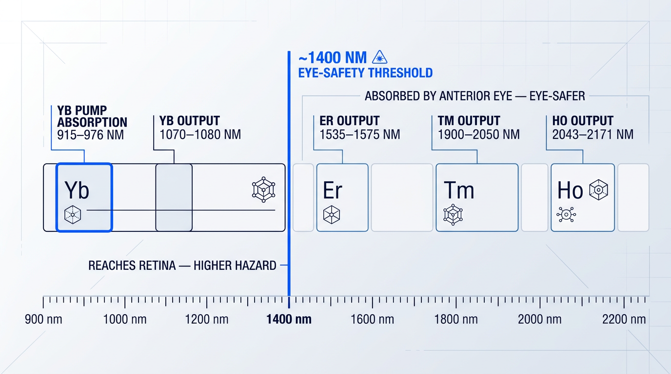
| Erbium (Er), often Er:Yb co-doped | ~1535–1575 nm | Ranging, free-space comms, lidar, sensing | Eye-safer wavelength; operates above 1400 nm retinal hazard threshold |
| Thulium (Tm) | ~1850–2100 nm | Medical ablation, atmospheric sensing, directed energy | Eye-safer, strong water absorption, cross-relaxation enables ~65% efficiency |
| Holmium (Ho) | ~2043–2171 nm | Surgical applications, mid-IR spectroscopy, atmospheric sensing | Longest silica-fibre wavelength; tunable across the 2 µm region |
Comparison of the four principal rare-earth dopants across output wavelength range, primary application domains, and key selection driver — enabling engineers to identify the right dopant for their application at a glance.
The table makes the trade-off clear: Yb is the default for applications where maximum power and efficiency are the primary objectives. Er and Tm become the preferred choices when the application demands operation above the ~1400 nm eye-safety threshold — whether for regulatory reasons, reduced hazard zone requirements, or specific material absorption properties such as the strong water absorption that makes 2 µm wavelengths effective in medical and atmospheric applications.
Holmium-doped fibre lasers extend coverage further into the 2 µm region, with demonstrated tunable output from approximately 2.04 to 2.17 µm. Beyond these fundamental dopant lines, wavelength coverage can be extended through second harmonic generation (SHG) — which has produced up to 200 W of green output at 532 nm from Yb fibre lasers — or through Raman shifting, which bridges the gaps between rare-earth emission bands across the 1.1–2.0 µm range.
The eye-safety threshold at approximately 1400 nm is not merely a physics curiosity — it has direct operational consequences. At wavelengths shorter than 1400 nm, the anterior structures of the eye are largely transparent, and the beam is focused onto the retina, where irradiance can be amplified by roughly five orders of magnitude relative to the corneal surface. Above 1400 nm, water absorption in the eye's anterior structures prevents light from reaching the retina, making Er (1550 nm) and Tm (1900–2050 nm) systems inherently eye-safer than Yb systems operating at 1060–1080 nm.
This distinction carries real weight in deployment planning: systems operating above 1400 nm attract different regulatory classification, enabling smaller nominal ocular hazard distances and making them operationally preferable in environments where controlling the hazard zone is a practical constraint — outdoor sensing, airborne applications, and certain military use cases among them.
Beam Quality Metrics: M² and BPP
Raw output power tells you how much energy a laser produces. M² (the beam propagation ratio) tells you what you can do with it. M² is defined as the ratio of the actual beam's divergence-waist product to that of an ideal diffraction-limited Gaussian beam: a perfect beam has M²=1, and any real beam has M²≥1, with higher values indicating faster divergence and reduced focusability.
What makes fibre lasers structurally distinctive is that single-mode fibre cores naturally preserve M² close to 1 regardless of output power — not because of careful alignment or active correction, but because the waveguide's refractive-index profile enforces single-mode propagation through the V-number condition (V ≤ 2.405). As documented across commercial fibre laser platforms, this beam quality is maintained across the full operating power range from 10% to 100% of rated output, with no change in divergence or beam profile.
Commercial single-mode Yb fibre lasers from IPG Photonics specify M² < 1.1 at powers up to 2 kW, M² < 1.15 at up to 4 kW, and M² < 1.2 at up to 5 kW — figures that reflect the structural beam quality preservation of the fibre waveguide rather than any active compensation.
The beam parameter product (BPP) is the companion metric to M², defined by ISO 11146 as the product of the beam waist radius and the half-angle divergence in the far field, expressed in mm·mrad. BPP and M² are directly proportional: BPP = M² × (λ/π), where λ is the wavelength. For a 1064 nm beam, the theoretical minimum BPP is approximately 0.34 mm·mrad, corresponding to a perfect Gaussian. Both metrics appear on commercial datasheets and describe the same underlying property — how tightly the beam can be focused.
BPP is the metric that most directly governs process capability: it determines the minimum achievable spot size at a given working distance, which in turn controls power density, cutting speed, penetration depth, and feature resolution. IPG Photonics' single-mode product lines specify BPP values below 1.0 mm·mrad (with 0.9 mm·mrad typical) for their lowest-order-mode configurations, while high-brightness multimode systems start at BPP values around 2 mm·mrad.
The choice between single-mode and multimode output is therefore an application-driven engineering decision, not a quality ranking. Single-mode output (M²~1, BPP below 1 mm·mrad, typical spot sizes of 30–100 µm) delivers the highest power density at the smallest spot, making it the right choice for precision cutting, fine welding, and additive manufacturing. Multimode output (M² values of 2 and above, spot sizes from ~100 µm to over 1 mm) suits applications where a larger illuminated area is acceptable or actively beneficial — thick-plate cutting, wide-area heat treatment, and surface processing where raw power matters more than tight focus.
Most procurement conversations start with power and treat beam quality as a secondary filter. The correct sequence runs the other way: BPP requirement first (derived from the spot size and working distance the process demands), power level second, architecture third. A laser with twice the wattage but twice the BPP delivers less usable intensity at the workpiece — not more.
The efficiency advantages of Yb's small quantum defect come with a thermal corollary: the fraction of pump energy that does not become signal light is deposited as heat in the fibre, and managing that heat load at high average powers is the central engineering challenge that the next section addresses.
Thermal Management: The Central Engineering Challenge
The difference between a well-engineered high-power fibre laser and a poorly engineered one rarely shows up on the spec sheet — it shows up in the thermal architecture. Power and beam quality are the headline numbers, but it is the thermal design that determines whether a system sustains those numbers under continuous load, degrades gracefully, or fails catastrophically. For engineers evaluating systems, thermal management deserves the same scrutiny as output power and M².
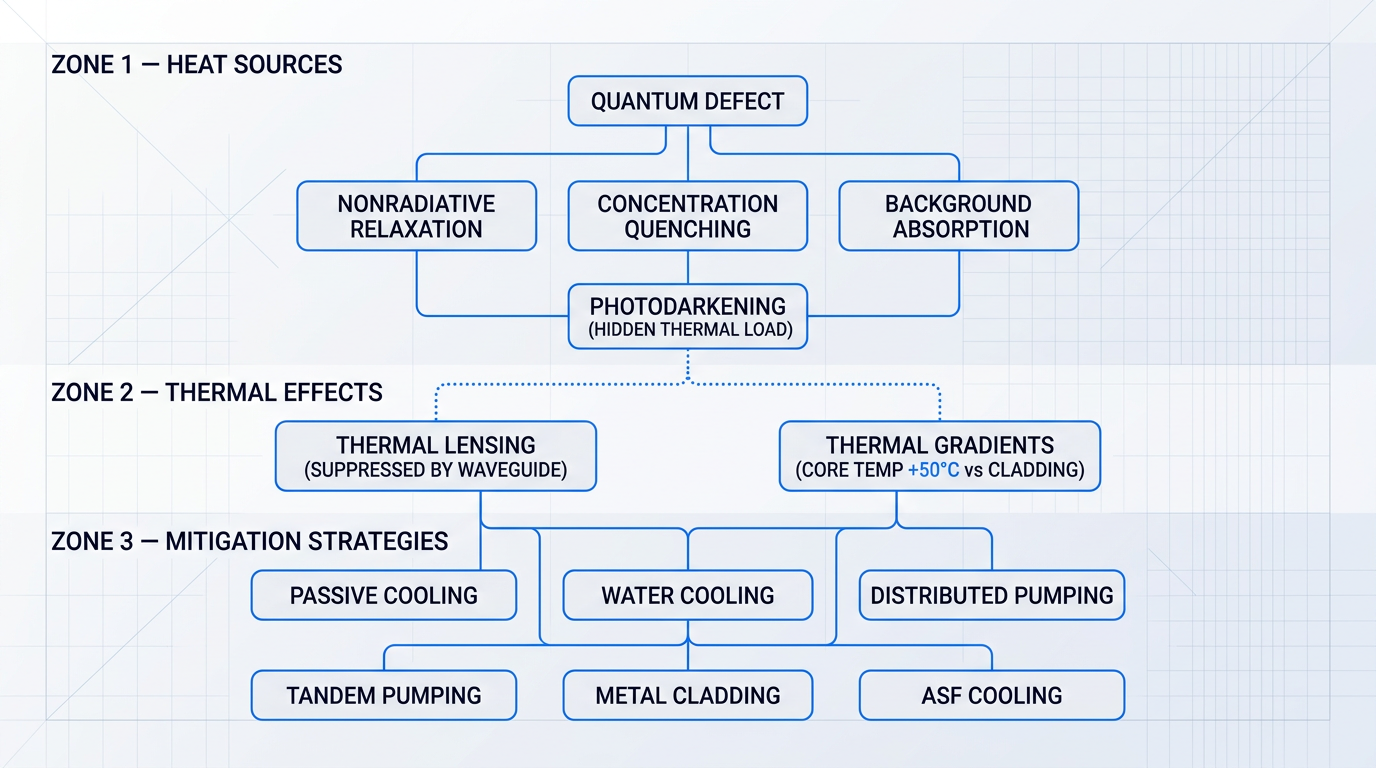
The primary heat source in any rare-earth-doped fibre laser is the quantum defect: pump photons carry more energy than the signal photons they generate, and the difference is deposited as heat directly in the doped core. The mechanism is straightforward — each absorbed pump photon promotes an ion to an excited state, and when that ion relaxes to the lower laser level before emitting a signal photon, the energy gap is shed as lattice vibrations (phonons) rather than light.
For an ytterbium-doped fibre pumped at 976 nm and lasing near 1030 nm, the quantum defect works out to approximately 5–6% of the pump photon energy. For a Nd:YAG laser pumped at 808 nm and lasing at 1064 nm, the same calculation gives 24.1%. That gap is not a minor detail — it is the quantitative foundation of Yb-fibre's thermal advantage over the solid-state technology it has displaced across much of industrial manufacturing.
The quantum defect for Nd:YAG (808 nm pump, 1064 nm output) is 24.1%, versus approximately 5–6% for Yb-doped fibre at 976 nm pump and ~1030 nm output. This structural thermal advantage is a primary reason Yb-fibre has displaced Nd:YAG in kilowatt-class industrial systems.
The quantum defect is the dominant heat source, but it is not the only one. The SPIE tutorial proceedings on fibre laser thermal physics identify a full taxonomy of contributors: nonradiative relaxation (excited ions decaying without emitting a photon, depositing energy directly as phonons); concentration quenching (ion-ion energy transfer at high doping concentrations that routes excitation into non-radiative decay rather than stimulated emission); and background absorption by impurities in the cladding glass, which adds a distributed heat load along the fibre length.
Photodarkening is a further heat source that warrants particular attention: it can become the dominant contributor in fibres that show only modest output power degradation, making it a hidden thermal load that is easy to underestimate. The mechanism and mitigation strategies for photodarkening are covered in depth in the following section — it is flagged here because any complete thermal audit of a high-power fibre system must account for it.
Fibre geometry confers a genuine structural thermal advantage over bulk solid-state gain media. The high surface-area-to-volume ratio of a long, thin fibre dissipates waste heat far more efficiently than a crystal rod or slab of equivalent gain, where heat must conduct outward through a much larger cross-section before reaching a cooled surface.
The waveguide structure also suppresses thermal lensing — a significant problem in bulk solid-state lasers, where thermally induced refractive index gradients across the gain medium distort the beam and degrade beam quality. In a fibre, the waveguide defines the guided mode regardless of thermal perturbations across the core, so beam quality is maintained even as the fibre heats up. This is a real architectural advantage, not a marginal one.
That advantage has limits, however. As average power increases, the residual heat per unit length of fibre rises with it. Research published in JOSAB has shown that for water-cooled fibres at high power, the core temperature can exceed the inner cladding temperature by as much as 50°C — sufficient to shift a nominally single-mode core towards multimode behaviour through the thermo-optic effect. At sufficiently high heat loads, thermal gradients also contribute to the onset of mode instability (addressed in the following section) and risk damage to the polymer jacket.
Practical Thermal Mitigation Strategies
Passive and forced-air cooling are viable thermal management approaches at lower average powers, and their viability at a given power level represents a genuine engineering achievement. A metal-clad ytterbium fibre laser producing 405 W of output without active water cooling or forced air — demonstrated in SPIE proceedings — illustrates what careful thermal design can accomplish: the system used a planar coil arrangement on a high-emissivity heatsink, achieved 74% slope efficiency, and produced a laser head weighing under 100 g.
For kilowatt-class systems, active water cooling becomes the standard approach. The heat load per unit length at these power levels simply exceeds what passive dissipation can manage: the fibre surface temperature would reach levels that risk jacket damage before sufficient heat could be conducted away.
Beyond the choice of cooling medium, system designers have several architectural and materials-level strategies available for managing the heat load itself — not just extracting it after the fact.
- Distributed pumping: Spreading pump injection along the fibre length rather than end-pumping reduces peak heat density at any single point, avoiding localised hot spots.
- Tandem pumping: Pumping the gain fibre with a fibre laser source near 1018 nm rather than diodes at 976 nm reduces the quantum defect per photon, directly cutting heat generation at the cost of added system complexity.
- Metal cladding designs: Replacing polymer outer claddings with metal-coated or metal-embedded designs improves radial heat extraction, lowering peak core temperature without changing system architecture.
Each of these strategies operates at a different level of the system. Distributed pumping is a design choice about where pump power enters the fibre; it reduces thermal gradients without altering the fundamental heat generation rate. Tandem pumping attacks heat generation at its root by shrinking the quantum defect — SPIE proceedings document single-mode Yb fibre lasers at 1018 nm with slope efficiencies of 78%, used as pump sources for multi-kilowatt tandem-pumped amplifiers — but requires a separate fibre laser pump source, adding both cost and complexity. Metal cladding is a materials-level complement to either approach, improving the rate at which heat escapes the fibre radially.
At the research frontier, anti-Stokes fluorescence cooling (ASF cooling) offers a conceptually elegant alternative: rather than extracting heat after it has been deposited, ASF cooling prevents net heating in the first place. The mechanism inverts the usual energy flow — by pumping the doped fibre at a wavelength longer than its mean fluorescence wavelength, the emitted fluorescence photons carry more energy than the absorbed pump photons, with the deficit drawn from the lattice thermal energy. The fibre cools rather than heats.
Laboratory demonstrations have confirmed laser cooling in Yb-doped silica glass fibre preform, with cooling efficiencies measured in carefully prepared samples. A related approach, dual-wavelength pumping, combines a conventional pump wavelength with an ASF-pumping wavelength to partially counteract heating without requiring net cooling. Both remain active research directions rather than commercially deployed techniques — the material purity and external quantum efficiency requirements are stringent — but they represent a plausible path toward radiation-balanced fibre lasers that generate no net heat at all.
When evaluating any high-power fibre laser system, thermal architecture should be interrogated with the same rigour as output power and beam quality. The relevant questions are concrete: Is the system air-cooled or water-cooled, and at what power level does it cross that threshold? What chiller infrastructure does the installation require? Has the manufacturer published thermal performance data, including core temperature rise at rated power? Air-cooled operation at a given power level is not a marketing claim — it is a specific engineering achievement with real operational consequences, including the absence of chiller infrastructure, simpler installation logistics, and greater system portability.
Thermal management addresses the heat problem inherent in converting pump photons to signal photons — but even with well-designed thermal architecture, the optical intensity confined within the fibre core creates a second class of constraints entirely. Those are the nonlinear optical effects that the next section addresses.
Nonlinear Optical Effects: SRS, SBS, and Mitigation
The fibre geometry that makes thermal management tractable — a small core, long interaction length, and high surface-area-to-volume ratio — is the same geometry that makes nonlinear optical effects unavoidable at high power.
Nonlinear effects scale with both optical intensity and interaction length; fibre waveguides maximise both simultaneously, concentrating kilowatts of signal power into a core measured in tens of microns across distances of several metres.
For system designers working above certain power thresholds, stimulated Raman scattering, stimulated Brillouin scattering, and self-phase modulation are not exotic edge cases — they are table-stakes constraints that must be designed around, not hoped away.
Stimulated Raman Scattering
Stimulated Raman scattering is an inelastic scattering process in which signal photons interact with vibrational modes of the silica host lattice, transferring energy to a frequency-downshifted Stokes wave at a longer wavelength.
In practice, SRS drains power from the intended output wavelength into this Stokes wave, degrading conversion efficiency and potentially damaging downstream optics that were not specified for the Stokes wavelength.
According to Laser Focus World's trade review of high-power fibre laser design, the SRS threshold in a standard single-mode fibre is reached at approximately 100 W — an order-of-magnitude reference point that shifts with fibre length, core size, and operating conditions, but gives designers a clear signal of when to start worrying.
The mitigation toolkit for SRS is straightforward: large-mode-area (LMA) fibre raises the threshold because the threshold power for nonlinear processes scales with the mode-field area of the fibre, so a larger core directly reduces intensity at a given power level; shorter fibre lengths reduce the Stokes gain by cutting the nonlinear interaction length; and careful fibre design choices can further suppress the effect.
Stimulated Brillouin Scattering
Stimulated Brillouin scattering arises from the interaction between the optical wave and acoustic phonons in the fibre, which creates a backward-propagating Stokes wave at a slightly downshifted frequency.
Unlike SRS, which propagates forward with the signal, the SBS Stokes wave travels back up the amplifier chain — where it can damage upstream components, destabilise the amplifier, and hard-limit power extraction.
Critically, the SBS threshold in a standard single-mode fibre is approximately 1 W for narrow-linewidth CW operation — roughly two orders of magnitude lower than the SRS threshold, making SBS the dominant nonlinear constraint for any CW system with a narrow spectral linewidth.
The SBS mitigation toolkit is richer than for SRS, with four principal strategies that can be applied individually or in combination.
- Large-mode-area fibre: Increasing core diameter raises the SBS threshold directly, as threshold power scales with mode-field area — the same mechanism that mitigates SRS.
- Spectral linewidth broadening: Phase modulation spreads optical power across a wider spectral band than the Brillouin gain bandwidth, raising the effective SBS threshold substantially.
- Acoustic profile engineering: Designing the fibre's acoustic index profile to minimise spatial overlap between the optical mode and acoustic mode reduces the SBS gain coefficient directly.
- Al₂O₃ dopant engineering: Al₂O₃ core doping increases the optical refractive index while decreasing the acoustic index, anti-guiding acoustic waves and reducing acoustic-optical overlap by over 6 dB.
In practice, LMA fibre and linewidth broadening are the first tools most designers reach for; acoustic profile and dopant engineering are applied when single-mode operation constraints limit how far core diameter can be increased, or when the linewidth budget is tight.
SBS suppression demands broad spectral linewidth, but coherent beam combining (CBC) demands narrow linewidth so that channels can be phase-locked. PRBS phase modulation resolves this directly: by applying a pseudo-random binary sequence pattern to the phase modulator, the linewidth is broadened sufficiently to suppress SBS while remaining deterministic and synchronised — enabling path-length-matched CBC without absolute path length matching. SPIE-documented demonstrations have achieved 5 kW of combined output from five PRBS-modulated 1.2 kW amplifiers at 82% combining efficiency.
PRBS phase modulation is the technically validated solution for engineers designing kilowatt-class CBC systems: it is not a research direction but a demonstrated approach, with published results showing near-diffraction-limited beam quality at multi-kW combined power levels.
Self-Phase Modulation
Self-phase modulation arises because the refractive index of silica is weakly intensity-dependent: at high peak intensities, a pulse's own electric field modifies the local refractive index as it propagates, causing the pulse's phase to evolve nonlinearly and broadening its spectrum.
SPM is primarily a constraint for pulsed and ultrafast systems rather than CW operation — it limits achievable pulse compression and can degrade frequency conversion efficiency in nonlinear stages, making it the dominant nonlinear challenge for the ultrafast science applications discussed later in this guide.
The primary mitigation is chirped pulse amplification (CPA): the pulse is stretched in time before entering the amplifier, reducing its peak intensity during amplification and therefore suppressing SPM; after amplification, the pulse is recompressed to its target duration.
Shorter fibre lengths and large-mode-area (LMA) fibre both reduce intensity at a given peak power, providing supplementary SPM suppression alongside CPA in ultrafast amplifier designs.
The Core Diameter Trade-Off
Increasing core diameter through large-mode-area (LMA) fibre is the universal first response to SRS, SBS, and SPM — but core diameter is not a free parameter that can simply be maximised.
Larger cores support more transverse modes, introducing the mode content challenges discussed earlier in this guide; at very large core sizes, the coupling between the fundamental and higher-order modes grows, increasing susceptibility to transverse mode instability (TMI) — the phenomenon that currently defines the practical ceiling for single-aperture high-brightness output.
System designers cannot optimise core diameter in isolation: every increase that suppresses SRS and SBS simultaneously tightens the TMI margin, and the design balance between these constraints is where the real engineering work happens.
The full nonlinear mitigation toolkit, summarised below, reflects this reality — each tool addresses a specific constraint but interacts with the others.
- LMA fibre design: Scales SRS, SBS, and SPM thresholds with mode-field area; primary mitigation across all three effects but bounded by TMI susceptibility.
- Fibre length optimisation: Shorter fibres reduce the nonlinear interaction length, cutting Stokes gain for both SRS and SBS at the cost of pump absorption efficiency.
- Spectral linewidth engineering: Phase modulation and PRBS modulation raise the SBS threshold by spreading power beyond the Brillouin gain bandwidth; essential for CBC systems.
- Acoustic profile and dopant engineering: Al₂O₃ doping and tailored acoustic index profiles reduce acoustic-optical overlap, suppressing SBS independently of linewidth or core size.
- Chirped pulse amplification: For pulsed and ultrafast systems, CPA stretches pulses before amplification to suppress SPM, then recompresses them to the target duration.
Managing these nonlinear effects is necessary but not sufficient for pushing single-aperture output to its practical limit — the next constraint, transverse mode instability, imposes a ceiling that the nonlinear toolkit alone cannot raise.
Transverse Mode Instability and Photodarkening: The High-Power Ceiling
At some point, adding more pump power to a single-aperture fibre laser stops producing more usable output. The beam quality collapses, or the system degrades over time in ways that no amount of cooling can fully arrest. This ceiling is not a pump brightness problem or a thermal management shortfall in the conventional sense — it is the consequence of two thermally coupled phenomena that operate at a deeper level: transverse mode instability (TMI) and photodarkening (PD).
Both effects are rooted in heat deposition in the fibre core, both emerge above specific power thresholds, and — critically — each makes the other worse. Understanding them separately is necessary; understanding how they interact is what separates a well-designed high-power system from one that surprises its operators after a few thousand hours of operation.
Transverse Mode Instability: Mechanism and Threshold
The underlying physics of TMI is stimulated thermal Rayleigh scattering (STRS): quantum defect heating along the fibre core creates a longitudinal temperature gradient, which induces a periodic refractive index grating via the thermo-optic effect.
That grating couples power from the fundamental mode (FM) into higher-order modes (HOMs) — and because the process is thermally driven and self-reinforcing, it is dynamic rather than static. The output beam, which may have been near-diffraction-limited at lower power, begins fluctuating on a millisecond timescale once the threshold is crossed.
That millisecond-scale fluctuation is what makes TMI particularly destructive in practice: it is not a gradual beam quality degradation that can be partially compensated, but a rapid, driven instability that renders the beam unusable for precision applications without warning.
In Yb-doped large-mode-area (LMA) systems, the TMI threshold typically manifests around 1 kW of average output power, though the exact value shifts with core diameter, doping concentration, fibre length, and operating conditions. This is also where the trade-off flagged in the previous section on nonlinear effects becomes concrete: larger cores suppress SRS and SBS but introduce more HOM content, which can lower the TMI threshold — there is no geometry that simultaneously optimises for both.
Managing TMI: The Engineering Toolkit
No single approach eliminates TMI — designers work with a set of complementary strategies, each addressing a different aspect of the STRS process.
- Tandem pumping: Using a fibre laser as the pump source rather than diode lasers reduces the quantum defect, cutting heat deposited per unit length and raising the effective TMI threshold.
- HOM-suppressing fibre design: Fibres engineered with elevated loss for higher-order modes — such as chirally-coupled core or leakage channel designs — suppress HOMs before they can accumulate meaningful power.
- Heat load modulation: Pulsing the seed or pump in controlled bursts induces a favourable phase shift between the thermal grating and the interference pattern, enabling operation above the conventional TMI threshold.
- Distributed pumping: Spreading pump absorption along a greater fibre length reduces peak thermal load per unit length, lowering the thermal gradient that drives STRS.
In practice, system designers combine several of these approaches simultaneously, accepting trade-offs at each step — tandem pumping adds system complexity; larger cores for HOM suppression require careful mode management; heat load modulation constrains operating duty cycle. The design space is genuinely constrained, not merely inconvenient.
Photodarkening: The Degradation That Moves the Goalposts
The thermal management section flagged photodarkening as an additional heat source beyond quantum defect. Here is the full account. Under sustained pump illumination, colour centres — defect sites in the Yb-doped silica matrix — form progressively in the fibre core, increasing absorption at both pump and signal wavelengths.
The absorbed energy converts to heat rather than signal photons, so output power falls while core thermal load rises. PD is not a sudden failure; it is a slow accumulation that compounds over the system's operational lifetime, making it especially insidious for long-duty-cycle deployments.
PD susceptibility scales with the square of the Yb doping concentration, meaning small increases in doping produce disproportionately large increases in colour centre formation rate. Aluminosilicate glass hosts — the most common matrix for high-power Yb-doped fibres — are significantly more susceptible than phosphosilicate hosts. Thulium-doped fibres, by contrast, show negligible PD, which is one reason Tm systems attract interest for high-power applications independent of their wavelength advantages.
The design tension this creates is real and has no universal resolution: longer fibres with lower doping concentrations reduce PD susceptibility, but this conflicts directly with the shorter-fibre preference for suppressing nonlinear effects established in the previous section. Every design is a negotiated compromise across these competing demands.
- Phosphosilicate glass host: Switching from aluminosilicate to phosphosilicate dramatically reduces PD susceptibility, at the cost of some changes to fibre fabrication and splicing compatibility.
- Cerium co-doping: Ce co-doping has been shown to substantially improve PD resistance in Yb-doped fibres, significantly reducing power degradation over extended operation.
- Photobleaching and thermal annealing: Exposing a PD-degraded fibre to elevated temperature or intense visible light can partially or fully restore initial transmission — a maintenance technique for long-lifetime systems.
- Lower inversion operation: Reducing the average excited-state population in the gain medium slows colour centre formation, at the cost of reduced gain efficiency.
Of these options, fibre composition engineering — phosphosilicate hosts and Ce co-doping — offers the most durable prevention. Photobleaching and thermal annealing are valuable for restoring degraded systems but are maintenance interventions, not substitutes for a PD-resistant fibre design from the outset.
Photodarkening does not just degrade output power — it raises the thermal load in the fibre core, which directly lowers the TMI threshold. A system operating cleanly at 1.2 kW on day one may begin exhibiting TMI after extended operation as PD accumulates. The practical power ceiling for high-brightness single-aperture systems is set by both effects acting in combination, not by either one in isolation.
This coupling is the central engineering reality above roughly 1 kW in a diffraction-limited beam: TMI defines the instantaneous ceiling, while PD progressively lowers that ceiling over the system's lifetime. Engineers evaluating high-brightness systems should ask OEMs specifically how the TMI threshold is managed in their fibre design, and should understand the PD lifetime implications before committing to long-duty-cycle applications.
These effects are also why beam combining architectures — covered earlier in this guide — exist as a scaling path: when the single-aperture ceiling is genuinely fixed by TMI and PD physics, combining multiple apertures is the only route to higher brightness. With the full picture of physical constraints now established, the next section turns to how high-power fibre lasers are actually deployed across industrial manufacturing applications, and what performance requirements each use case imposes on system design.
High Power Fiber Lasers in Industrial Manufacturing
All the parameters covered in the preceding sections — beam parameter product, M², thermal limits, TMI thresholds — exist because real manufacturing processes impose real requirements on the laser source. This section is where those abstractions become engineering decisions: which beam quality does a given process actually demand, and what happens when the source falls short?
Laser Cutting: Beam Quality as a Process Parameter
In thin-sheet cutting, raw wattage is a secondary variable — BPP is the primary one. Research comparing sources with BPPs of approximately 4 mm·mrad and 23 mm·mrad at equivalent average power found that the lower-BPP fibre laser delivered around 70% greater penetration depth at a given cutting speed, and roughly 250% higher cutting speed for a fixed penetration target.
The mechanism is straightforward: a tighter focused spot produces higher power density at the kerf, which drives faster melt ejection and narrower cut widths — outcomes that no amount of additional average power from a lower-brightness source can replicate at the same spot size.
Thick-plate cutting inverts this logic deliberately. For material above roughly 10–15 mm, a larger spot — and therefore a higher BPP — is preferred: it produces a wider kerf, supports better assist-gas dynamics, and allows melt to eject more effectively from a deeper cut channel. Single-mode, high-brightness output is not the optimal choice here; multimode sources are selected intentionally.
This thin-versus-thick trade-off has driven development of tunable-beam-quality platforms. nLIGHT's Corona technology is a concrete industry response: an all-fibre architecture that allows the beam profile to be adjusted electrically between near-single-mode and larger ring-shaped outputs, enabling a single laser platform to address both cutting regimes without a hardware change.
The practical implication for procurement is that specifying a fibre laser for cutting should begin with the material thickness range and kerf requirements — the beam quality specification follows from those constraints, not the other way around.
Laser Welding: Keyhole vs Conduction Mode
Keyhole welding uses high power density — achieved through a tight focused spot and correspondingly low BPP — to vaporise material and create a narrow vapour channel that allows the beam to penetrate deep into the workpiece. The result is a high-aspect-ratio weld profile with a narrow fusion zone, minimal heat-affected zone, and high travel speed: the mode of choice for thick joints and high-throughput production.
Conduction welding uses a larger spot and lower power density, producing a shallow, smooth weld bead without keyhole formation. It is the preferred mode for thin parts, cosmetically sensitive joints, and applications where post-weld finishing must be minimised.
The BPP requirement tracks directly with mode: deep-penetration keyhole welds demand near-single-mode output to sustain the power density required, while seam welds and heat-affected-zone-sensitive applications can tolerate — and sometimes benefit from — a larger, multimode spot that distributes heat more broadly.
One practical advantage of fibre lasers over CO₂ sources in welding is depth of focus. Because fibre lasers operate at approximately 1 µm wavelength — roughly one-tenth that of CO₂ — they achieve 10–30× greater depth of focus at the same spot size. In production environments where part tolerances cause the focal plane to shift between components, this extended depth of focus maintains consistent power density without requiring active focus correction.
Research comparing fibre, disk, Nd:YAG, and CO₂ sources across the same materials and optical configurations confirms that BPP and focused spot size — not laser type or wavelength per se — are the variables that determine welding penetration and speed for a given brightness level.
Surface Treatment and Cleaning
The unifying capability across laser surface treatment applications — pre-weld oxide removal, pre-bond surface activation, rust and scale removal, mould cleaning, and coating stripping — is selective ablation: the laser removes the contaminant or surface layer while leaving the base substrate intact.
Selectivity is governed by the absorption contrast between the contaminant and the substrate. Where that contrast is high, the contamination absorbs the laser energy and vaporises or ablates before the underlying material reaches damaging temperatures. The process requires careful control of fluence — enough to remove the target layer, not enough to damage what lies beneath.
For precision cleaning tasks — mould cleaning, delicate coating removal, substrate-sensitive de-rusting — pulsed MOPA architecture at 100–300 W average power is particularly well suited. Independent control of pulse duration, repetition rate, and peak power allows the thermal dose to be tuned specifically to the contamination type and substrate sensitivity, without the substrate damage risk that continuous-wave operation at equivalent average power introduces.
Comparative testing of MOPA pulsed and CW fibre lasers on the same cleaning tasks has found that pulsed MOPA delivers substantially lower post-cleaning surface roughness — in some cases leaving the substrate smoother than its pre-contamination state — while CW cleaning at equivalent average power increases surface roughness by approximately 1.5× and risks thermal damage to the substrate if scan speed is not precisely controlled.
Wavelength selection carries operational consequences beyond process performance. Wavelengths above approximately 1,400 nm are absorbed by the anterior structures of the eye rather than transmitted to the retina, which changes the ocular hazard profile relative to the 1,064 nm Yb-fibre band. For cleaning deployments in open workshops or mixed-use environments — where full beam enclosure is impractical — this wavelength characteristic is a genuine engineering consideration when assessing exclusion zone requirements and operator safety management.
Additive Manufacturing: Beam Quality as a Process Variable
In laser powder bed fusion (L-PBF), beam quality is not a background specification — it is a direct process parameter. The tight, stable focused spot that single-mode output provides is what governs melt-pool geometry consistency and fine feature resolution across a build.
The challenge at higher power levels is that simply increasing laser power with a standard single-mode Gaussian beam causes keyholing and melt-pool instability, generating spatter and porosity that degrade part quality. The conventional response — enlarging the spot to reduce power density — sacrifices the resolution advantage of single-mode output.
Dynamic beam shaping addresses this directly. nLIGHT's AFX-2000 uses an all-fibre beam shaping architecture to switch between a true single-mode Gaussian core and an annular ring profile, distributing power across a larger area without the instability that accompanies a defocused Gaussian. The AFX-2000 delivers 2 kW with this capability, and nLIGHT reports that it can deliver twice the available power of current single-mode systems while maintaining a stable melt pool — enabling higher build rates without the quality penalties that would otherwise accompany the power increase.
Typical per-beam power in L-PBF systems runs from 200 W to 2 kW; multi-beam machines use several fibre laser sources scanning in parallel to increase build area coverage and overall throughput without requiring a single source to operate at the upper end of the power range.
Wall-Plug Efficiency and Footprint in Production
The efficiency and footprint advantages of fibre lasers are not merely technical talking points — they translate directly into manufacturing economics. Ytterbium fibre lasers achieve wall-plug efficiency exceeding 40% in standard industrial configurations, with leading designs surpassing 50%; lamp-pumped Nd:YAG systems typically achieve 1–3% electrical-to-optical efficiency, with diode-pumped solid-state designs reaching perhaps 10–20%.
In continuous production environments running high duty cycles, that efficiency gap compounds into a substantial operating cost differential — reduced electricity consumption, lower cooling load, and elimination of consumables such as flashlamps.
| Parameter | Yb Fibre Laser (4 kW) | Lamp-Pumped Nd:YAG (4 kW) |
|---|---|---|
| Wall-plug efficiency | >40% (leading designs >50%) | 1–3% (lamp-pumped); up to ~10% diode-pumped |
| Floor space footprint | ~0.5 m² | ~11 m² |
| Cooling requirement | Low (often air-cooled or minimal chiller) | Active chiller required |
| Consumable replacement | None during rated lifetime | Periodic flashlamp replacement |
Comparison of fibre laser vs lamp-pumped Nd:YAG on the two manufacturing economics metrics most relevant to production floor decisions: efficiency and footprint.
The footprint figure is particularly significant in space-constrained facilities: a 4 kW fibre laser occupies roughly 0.5 m² of floor space versus approximately 11 m² for a lamp-pumped Nd:YAG system of equivalent output. That 22-fold reduction in floor area is what makes fibre lasers practical to integrate into existing production lines rather than requiring dedicated laser bays.
A 4 kW Yb fibre laser occupies ~0.5 m² of floor space and converts more than 40% of input electricity to usable light. An equivalent lamp-pumped Nd:YAG requires ~11 m² and achieves 1–3% efficiency. These figures — not beam quality alone — explain why fibre lasers are now the default choice for new industrial laser installations.
Industrial manufacturing represents the largest installed base for high power fiber lasers by a considerable margin — but the same fibre laser architectures that drive cutting tables and welding cells are deployed in very different performance regimes for scientific research and defence applications, where the demands on beam quality, spectral purity, and power scaling take a different shape entirely.
Scientific, Research, and Directed-Energy Applications
Industrial manufacturing accounts for the largest installed base of high power fiber lasers — but it is not where these systems are pushed hardest. Scientific research demands wavelength agility, spectral purity, and temporal precision that raw power cannot substitute for. Directed-energy defence demands the highest possible beam quality at extreme power levels inside ruggedised, field-deployable hardware. These two domains are where every architectural and engineering decision covered in this guide — beam combining, SBS suppression, TMI management — translates into concrete, high-stakes system requirements.
Scientific and Research Applications
In scientific instrumentation, fibre lasers rarely appear as the end product — they are the enabling source that makes other, more specialised sources possible.
Wavelength extension into the mid-infrared is one of the most significant contributions. Thulium-fibre-pumped Cr:ZnSe lasers deliver over 10 W of continuously tunable CW output across the 2–2.8 µm range, while Yb-fibre-pumped optical parametric oscillators (OPOs) cover 1.4–4.6 µm with output reaching 35 W. The stable, high-brightness output of the fibre pump is what makes this wavelength coverage practical — the OPO or Cr:ZnSe crystal is doing the frequency conversion, but it depends entirely on the quality of the seed.
Second-harmonic generation (SHG) of Yb-fibre output to 532 nm green is a commercially mature route to visible-wavelength sources. Green fibre laser systems are available at average powers from tens of watts into the quasi-CW regime, with applications spanning spectroscopy, lidar, and materials science — domains where the 532 nm wavelength offers favourable absorption characteristics and where fibre-based sources provide the beam quality and stability that gas or solid-state alternatives struggle to match.
At the other end of the power scale, single-frequency, narrow-linewidth fibre sources serve spectroscopy, atom trapping, and atomic clock applications where wavelength stability matters far more than output power. These sources operate in a single resonator mode, achieving linewidths from MHz down to the kHz range. As established in the discussion of nonlinear effects, narrow linewidth is also the condition that makes SBS onset most acute — the same spectral purity that makes these sources scientifically valuable makes them the most SBS-susceptible configuration in the fibre laser family.
Ultrafast Science: MOPA, CPA, and Peak Power
MOPA architectures, introduced earlier in this guide, are the foundation of fibre-based ultrafast laser systems. Combined with chirped pulse amplification (CPA) — which stretches a pulse in time before amplification then recompresses it afterward — MOPA configurations enable femtosecond and picosecond pulse generation at average powers reaching well above 100 W.
The practical case for fibre-based ultrafast systems over Ti:sapphire is deployability: compact footprint, maintenance-free operation, and no alignment-sensitive free-space cavity. Ti:sapphire remains unmatched for the very highest pulse energies and shortest pulses, but Yb-fibre MOPA/CPA systems offer higher average power, far more flexible repetition rates (up to the megahertz regime), and the rugged, turn-key operation that makes them viable outside a controlled laboratory environment.
The challenge is that the same fibre geometry that concentrates intensity for efficient thermal management also accumulates self-phase modulation (SPM) in short pulses. SPM causes spectral broadening and phase distortion that limits compressed pulse quality — CPA mitigates but does not eliminate this effect, and managing the nonlinear phase budget is the central design challenge in high-energy fibre CPA systems. Rod-type photonic-crystal fibre amplifiers, with their large mode areas, reduce nonlinear accumulation and have enabled gigawatt-class peak powers in femtosecond CPA systems, representing the current frontier of fibre-based ultrafast performance.
Power Beaming: An Emerging Application
Laser power beaming — wireless power transmission via a directed laser beam to a photovoltaic receiver — is an emerging application that depends specifically on the beam quality properties of single-mode fibre sources. Because optical fibres are largely immune to thermal lensing, the beam profile of a fibre laser remains stable as output power is modulated, which is essential for maintaining efficient coupling to a remote receiver across varying transmission distances.
Demonstrations have advanced substantially: DARPA's POWER programme delivered over 800 W at a distance of 8.6 km in ground-based tests, and PowerLight Technologies has demonstrated kilowatt-class power delivery to airborne UAVs. These are real engineering demonstrations, not laboratory curiosities — but power beaming remains an emerging domain, and the system integration challenges (pointing, atmospheric effects, receiver efficiency) are as significant as the laser source itself.
Defence and Directed-Energy Applications
Directed-energy (DE) weapons are where the engineering properties of high-power fibre lasers matter most, and where the consequences of getting them wrong are highest. Four properties make fibre lasers the architecture of choice for fielded DE systems: wall-plug efficiency exceeding 40% (reducing the thermal and logistical burden on mobile platforms), near-diffraction-limited beam quality, all-fibre construction that eliminates alignment-sensitive free-space optics, and robust operation across the dust, vibration, and temperature extremes of field environments.
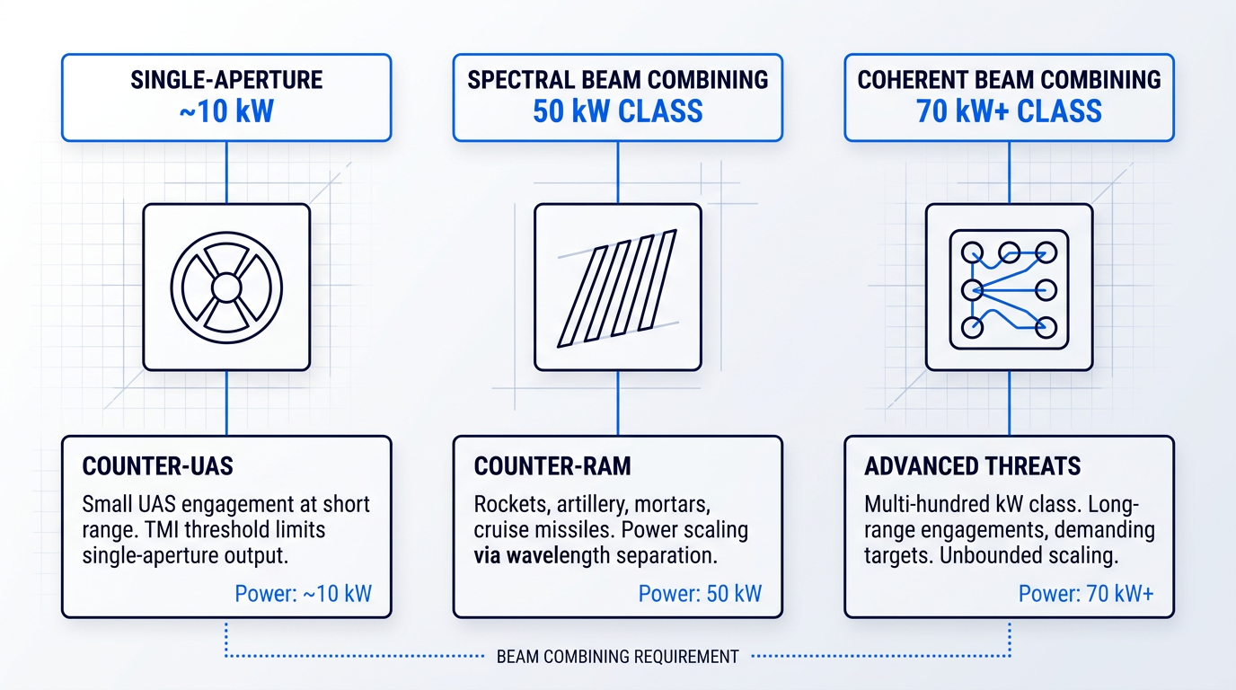
DE mission profiles impose distinct power-level requirements, and understanding them clarifies why beam combining is not optional — it is the only viable scaling path.
- Counter-UAS (~10 kW class): Engaging small unmanned aerial systems at relatively short range; achievable with single-aperture near-diffraction-limited fibre sources at the TMI threshold.
- Counter-RAM (30–100 kW class): Defeating rockets, artillery, mortars, and cruise missiles requires power levels well beyond what a single fibre aperture can deliver with good beam quality.
- Advanced threats (multi-hundred kW): Longer-range engagements and more demanding targets push requirements toward several hundred kilowatts, where beam combining is the only practical architecture.
The critical link between the technical constraints discussed earlier and these mission profiles is the TMI-imposed single-aperture ceiling: as established in the section on transverse mode instability, near-diffraction-limited output from a single fibre aperture is practically limited to roughly 10 kW before TMI degrades beam quality. Counter-UAS sits right at that boundary. Everything above it requires beam combining — and the architecture of that combining determines whether the resulting system can actually meet the beam quality requirements that make a DE weapon effective.
Spectral beam combining (SBC) was the first approach to reach fielded power levels. Lockheed Martin's 50 kW-class SBC system, selected by the US Army for integration into the High Energy Laser Mobile Demonstrator, combines fibre channels operating at slightly different wavelengths using a diffraction grating, requiring no active phase control — a significant ruggedisation advantage. The trade-off is that power scaling is bounded by the available gain bandwidth; SBC cannot be extended indefinitely without sacrificing beam quality or spectral efficiency.
Coherent beam combining (CBC) removes the bandwidth constraint by phase-locking multiple fibre amplifier channels to produce a single combined beam. AFRL's LOCSET technique — Locking of Optical Coherence by Single-Detector Electronic-Frequency Tagging — demonstrated this at kilowatt-class power levels, with the architecture assessed as scalable to combinations of over 100 fibre amplifiers. nLIGHT's HADES programme, built on CBC with integrated atmospheric correction, has delivered a 70 kW-class system for counter-UAS and counter-RAM missions, with subsequent HELSI programme work advancing toward much higher power levels.
CBC requires narrow-linewidth amplifiers to maintain phase coherence across channels — but narrow linewidth is precisely the condition that makes SBS onset most severe. The PRBS phase modulation technique discussed in the nonlinear effects section is the primary mitigation, making SBS suppression not an abstract nonlinear physics problem but the core engineering constraint that determines how many channels can be coherently combined at kilowatt-class per-channel power.
One system integration challenge sits beyond the laser source itself: atmospheric propagation. Thermal blooming, turbulence, and wavelength-dependent absorption all degrade the irradiance delivered to a distant target. These effects are managed through adaptive optics and beam control systems rather than laser design, but engineers evaluating DE systems need to account for them — the laser's near-field beam quality does not directly translate to on-target performance without considering the propagation path.
With the full application landscape now mapped — from mid-infrared scientific sources through ultrafast CPA systems to directed-energy weapons — the guide's closing section consolidates these threads into a practical evaluation framework for engineers selecting and specifying high-power fibre laser systems.
Conclusion
Evaluating High Power Fiber Lasers: A Decision Framework
The most useful shift this guide can leave you with is a simple inversion: start from what your application actually requires, not from what the spec sheet offers.
That means anchoring your evaluation on beam quality first, then working outward through thermal architecture and system configuration — whether single-emitter, MOPA, or beam-combined — to find the design that delivers it at the power level you need.
For questions that remain, the FAQ section below addresses the specifics; for deeper system work, your OEM's application engineering team is where that conversation belongs.
Frequently Asked Questions About High Power Fiber Lasers
Practical answers to the engineering and procurement questions that a guide's narrative cannot always address in full — each answer stands on its own.
Start with beam quality, not power. Determine the spot size your process requires at the working distance you need, then derive the beam parameter product (BPP) that delivers it. Once you know the BPP ceiling, identify the average power the process speed demands. Only then select the architecture — single-mode or multimode, CW or pulsed, air-cooled or water-cooled — that satisfies all three simultaneously. Specifying power first and beam quality second is the most common mistake in fibre laser procurement. A 3 kW single-mode source and a 3 kW multimode source are not interchangeable: the single-mode unit will focus to a far smaller spot, enabling finer cuts or deeper keyhole welds, while the multimode unit may offer lower capital cost and simpler thermal management. If your process is beam-quality-limited — precision cutting of thin sheet, fine welding, or surface texturing — the BPP constraint will determine your architecture before power enters the conversation. If your process is purely power-limited — bulk heating, wide-area cladding — multimode at lower cost per watt is often the right call. When in doubt, contact the OEM's application engineering team with your spot size, working distance, and throughput target: those three numbers will drive the specification more reliably than any datasheet comparison.
The answer depends on what you mean by 'single fibre laser.' For near-diffraction-limited, single-aperture output, the practical ceiling is set by transverse mode instability (TMI) and nonlinear effects including stimulated Raman scattering (SRS) and stimulated Brillouin scattering (SBS) — above a threshold average power, beam quality degrades rapidly and the output becomes unusable for precision applications. For multimode single-aperture output, where beam quality is relaxed, commercial systems from major OEMs are available at substantially higher power levels, and industrial CW fibre laser platforms have been demonstrated well into the tens of kilowatts. For applications where raw power matters more than focusability, this is a viable route. For beam-combined systems, where multiple fibre laser apertures are coherently or spectrally combined, output well above what any single aperture can achieve has been demonstrated — this is the architecture used in directed-energy programmes rather than standard industrial products. In short: the single-aperture brightness ceiling is a physical constraint driven by TMI and nonlinear effects; higher power is available by relaxing beam quality or by combining apertures.
Pulsed fibre lasers — typically configured as master oscillator power amplifiers (MOPAs) — deliver high peak power in short bursts, allowing selective ablation of surface contamination with minimal heat transfer to the underlying substrate. This makes them the preferred choice for precision cleaning, mould cleaning, and sensitive materials where thermal damage to the base material is a genuine risk. CW fibre lasers deliver a continuous beam at lower peak power, which means more cumulative heat input per unit area. They are simpler to operate and typically lower in capital cost, but on thermally sensitive substrates they can cause discolouration, micro-cracking, or surface modification that pulsed operation avoids. The three parameters that govern process outcome in pulsed cleaning are pulse duration, pulse repetition rate, and average power. Reducing repetition rate at fixed pulse energy raises peak power per pulse, improving ablation efficiency; raising repetition rate increases average power and heat input, moving the process closer to CW behaviour. Engineers optimising a cleaning process tune all three interactively. A further consideration for open-environment or field cleaning applications: fibre lasers operating at longer wavelengths — such as Er-doped systems around 1550 nm — are classified as eye-safer than the dominant Yb-fibre wavelength near 1 µm, which can be relevant where full beam enclosure is impractical.
Each technology has genuine strengths, and the right choice is application-dependent. On beam quality, single-mode fibre lasers achieve a significantly lower beam parameter product than CO2 lasers, enabling smaller focused spots at equivalent power — an advantage for precision cutting and welding of metals. On electrical efficiency, Yb-fibre lasers convert electrical input to optical output at substantially higher efficiency than lamp-pumped Nd:YAG, which translates to meaningful operating cost differences in continuous production. On beam delivery, fibre lasers route the output through a flexible fibre cable to a remote processing head, integrating naturally into robotic cells and multi-axis systems. CO2 lasers require free-space beam delivery through mirrors and beam-steering optics, which adds mechanical complexity and limits flexibility in automated lines. The area where CO2 retains a genuine advantage is non-metallic materials. CO2's 10.6 µm wavelength is strongly absorbed by polymers, ceramics, wood, and glass — materials that are largely transparent or poorly absorbing at the approximately 1 µm wavelength of fibre lasers. For cutting acrylic, engraving wood, or processing glass, CO2 remains the more practical choice. Lamp-pumped Nd:YAG has largely been displaced by fibre lasers in new installations due to the efficiency gap, though pulsed and diode-pumped Nd:YAG variants retain niches in certain marking and micro-machining applications.
The term refers to a wavelength threshold at approximately 1400 nm. Below this threshold — including the dominant Yb-fibre wavelength range near 1060–1080 nm — light passes through the eye's cornea and lens and is focused onto the retina. The eye's own optics concentrate the energy onto a very small area, meaning retinal damage can occur even at relatively low power levels, and the injury may be permanent. Above approximately 1400 nm, the cornea and lens absorb the radiation before it reaches the retina, distributing the energy over a much larger tissue area and significantly reducing the risk of retinal injury. This is why Er-doped fibre lasers operating around 1550 nm and Tm-doped fibre lasers in the 1900–2050 nm range are described as 'eye-safer.' Two important clarifications follow. First, eye-safer does not mean safe without precautions: high-power fibre lasers at these wavelengths can still cause serious injury to the cornea and skin, and engineering controls, interlocks, training, and appropriate PPE remain necessary. Second, the practical operational benefit is a reduction in the laser hazard zone — the calculated safe distance from the beam. A smaller hazard zone has real deployment consequences, potentially allowing operation in open workshops or mixed-use facilities where a system at 1064 nm would require a fully enclosed laser safety area.
Transverse mode instability (TMI) is a thermally driven phenomenon in which a high-power fibre laser's output beam begins fluctuating rapidly above a threshold average power level. Below the threshold the beam is near-diffraction-limited and stable. Above it, the output degrades into a time-varying mixture of the fundamental mode and higher-order modes on a millisecond timescale, making it unusable for precision processing. The physical mechanism is a thermally induced refractive index grating in the fibre core that couples energy from the fundamental mode into higher-order modes. TMI is the primary reason single-aperture diffraction-limited power from a fibre laser is limited — it sets the ceiling that beam combination architectures are designed to circumvent. For system selection, the practical implication is that any engineer specifying a high-brightness fibre laser at elevated average power should ask OEMs specifically how TMI is managed in their design. Mitigation approaches — including tandem pumping, optimised fibre geometry, and careful heat load management — vary by product and are not always disclosed in datasheets. There is also a coupling effect worth noting: photodarkening, the gradual increase in fibre absorption caused by colour-centre formation under pump exposure, reduces gain efficiency over time and can lower the effective TMI threshold. A system that performs to specification initially may degrade over months of operation, so long-term stability data should be part of any procurement evaluation alongside the initial datasheet figures.