
Why Architecture and Application Must Align
A high-power fibre amplifier boosts an optical signal to the levels a demanding application requires, entirely within the optical domain. LiDAR, free-space optical communications, defence, and sensing all depend on this capability.
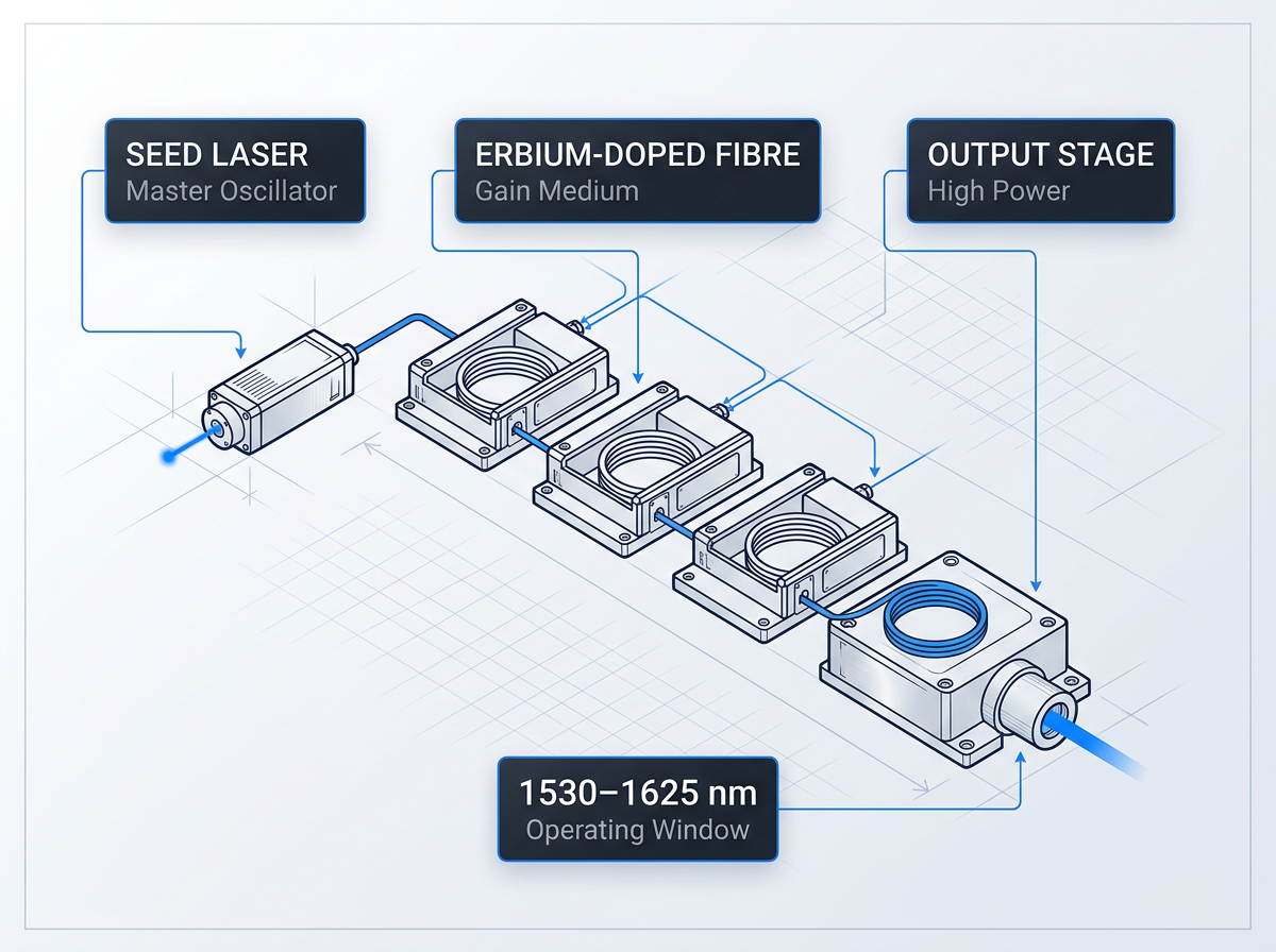
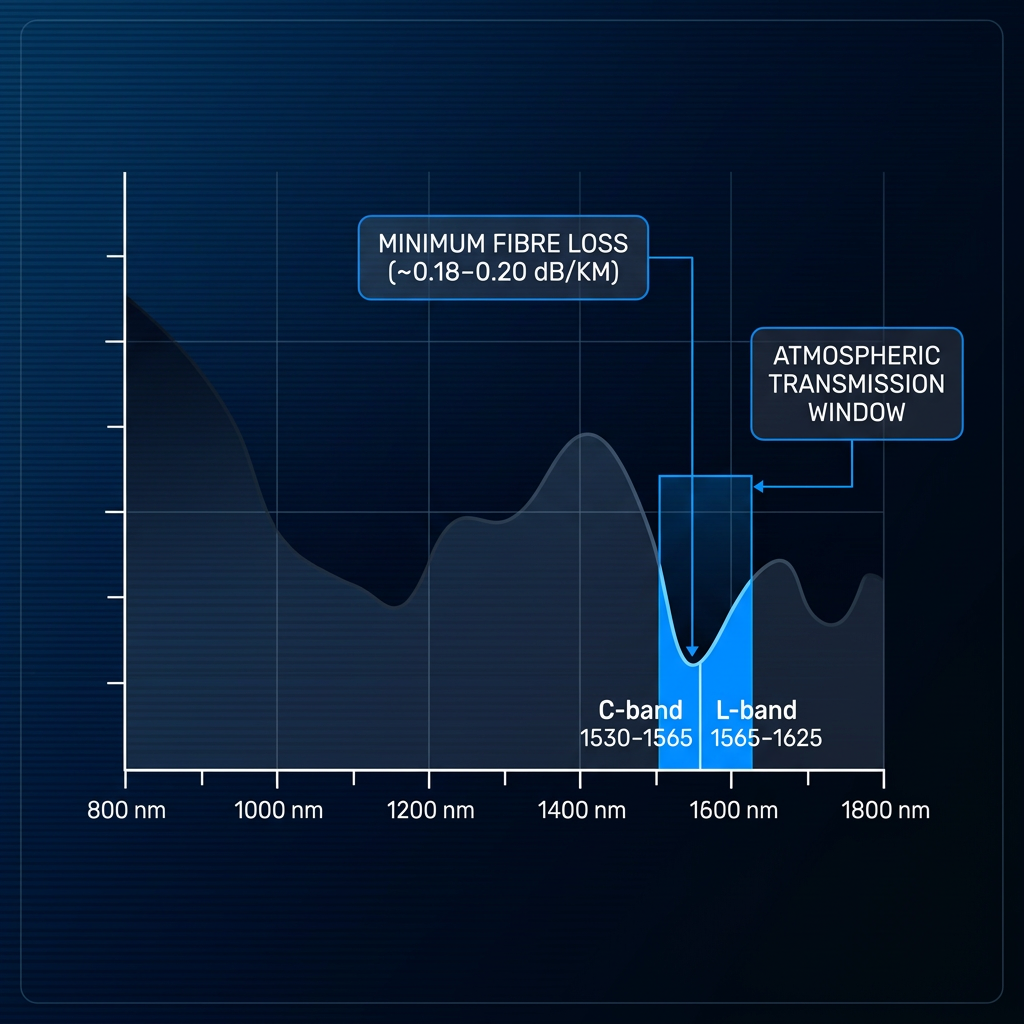
The established architecture is MOPA: a seed laser feeding multi-stage amplification through erbium-doped fibre, across the 1530–1625 nm window — the minimum-loss band of silica fibre.
Operating band, output power, pulse regime, and integration envelope all shift what an amplifier delivers. A catalogue part fixes those variables for you. For demanding work, the amplifier must be built around the application — not the other way round.
Power Performance Specifications
Every figure below is a configurable performance ceiling, built to the client's requirement. Average power, pulse energy and peak power are all scalable per project — these are not fixed SKU specifications but the current expression of what WSL engineers to order.
Average Power: Up to 200 W or More
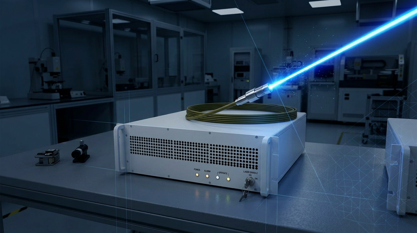
Builds to 200 W or more — the highest average power commercially available.
Pulse Energy: Above 10 mJ
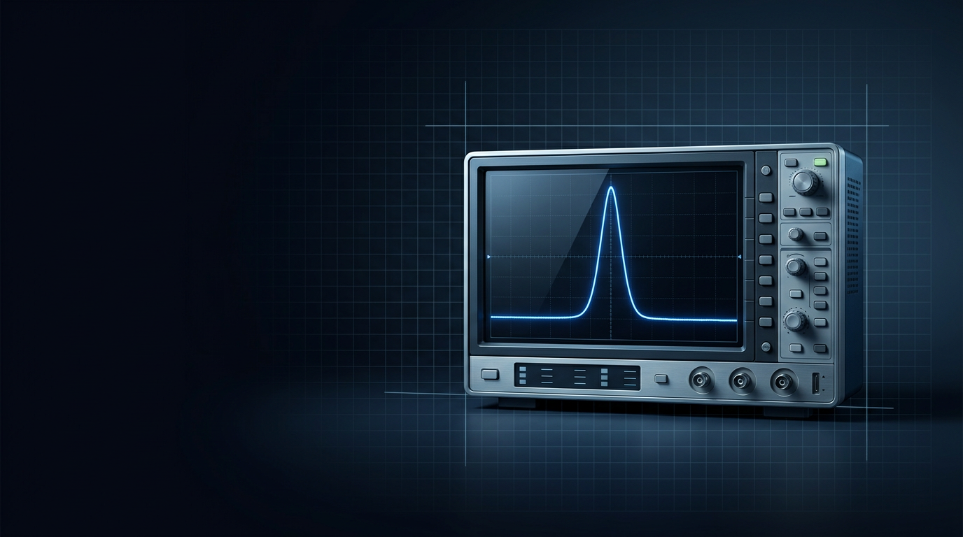
Pulse energies above 10 mJ, specified and configured per project to the application's requirement.
Peak Power: Above 100 kW
Peak powers above 100 kW, configurable per project to meet the application's demands.
Full Output Control: 0 to 100%
Output continuously tunable from 0 to 100% of rated power, no fixed steps.

Built to Your Power Requirement
Every unit engineered to the client's specification. Requirements beyond published figures are assessed directly.
C-band, L-band, or Both
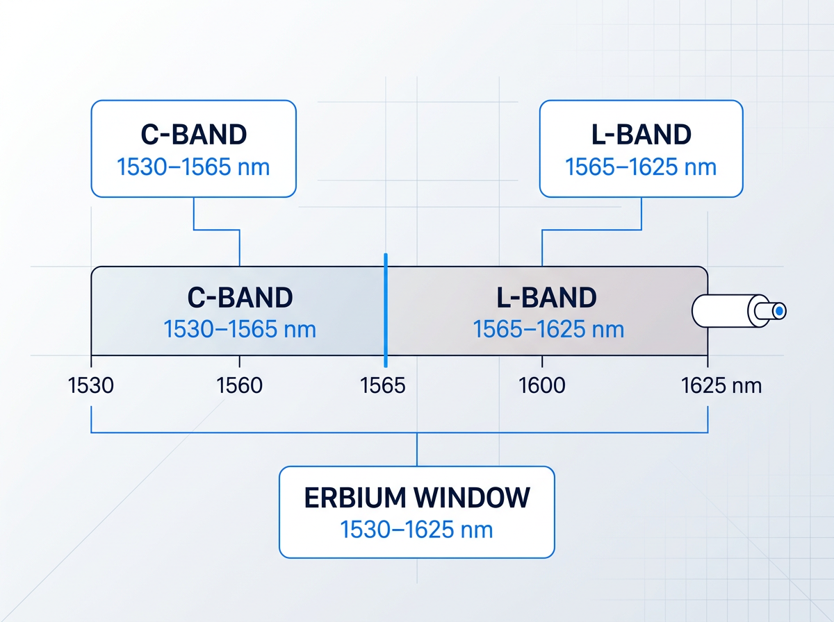
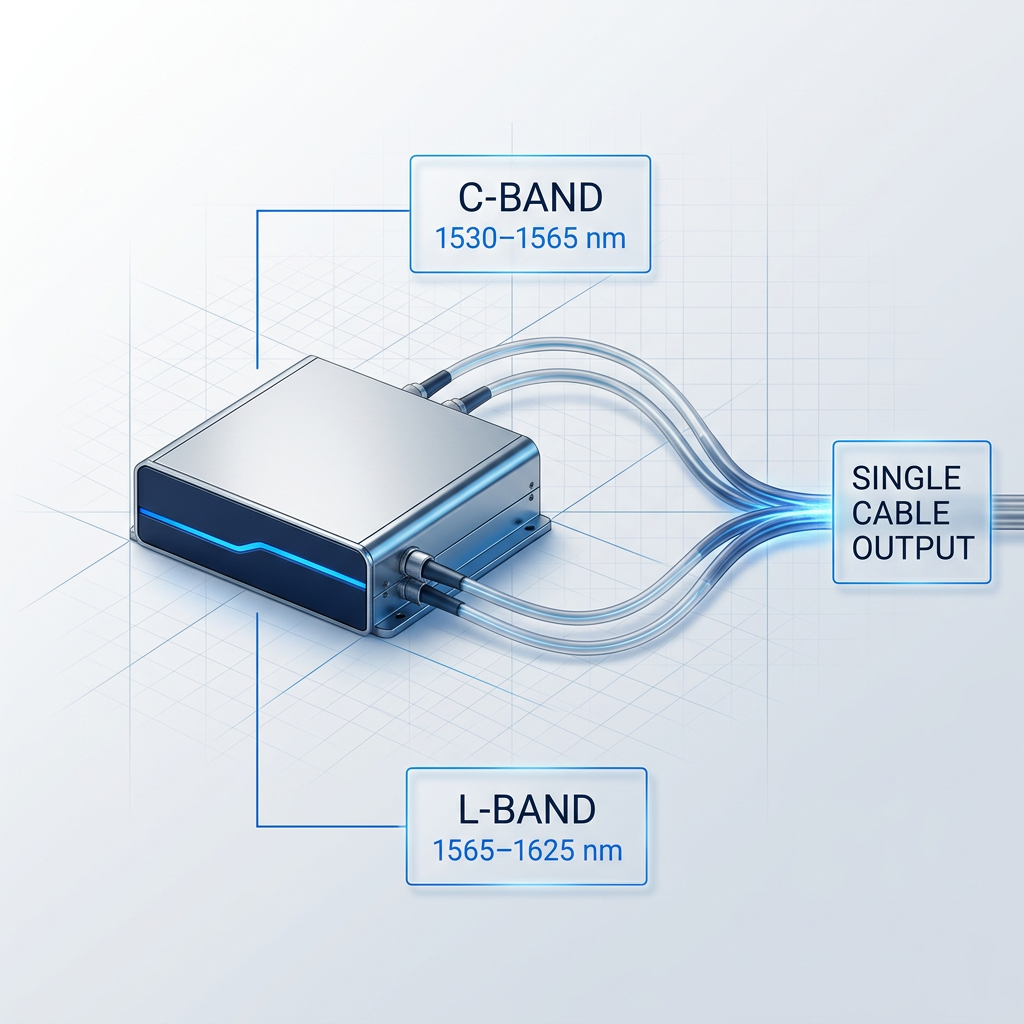
The Custom EDFA operates across the C-band (1530–1565 nm), the L-band (1565–1625 nm), or both simultaneously — delivered through a single cable from a single amplifier, with no second source required.
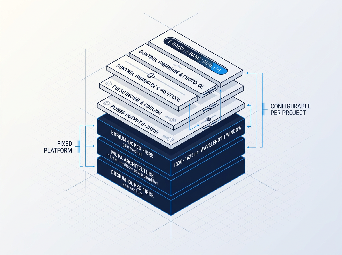
Band selection is specified per project. Whether your optical architecture demands C-band, L-band, or dual C+L coverage, the amplifier is built to match it — not the other way around.
Power Built to Spec
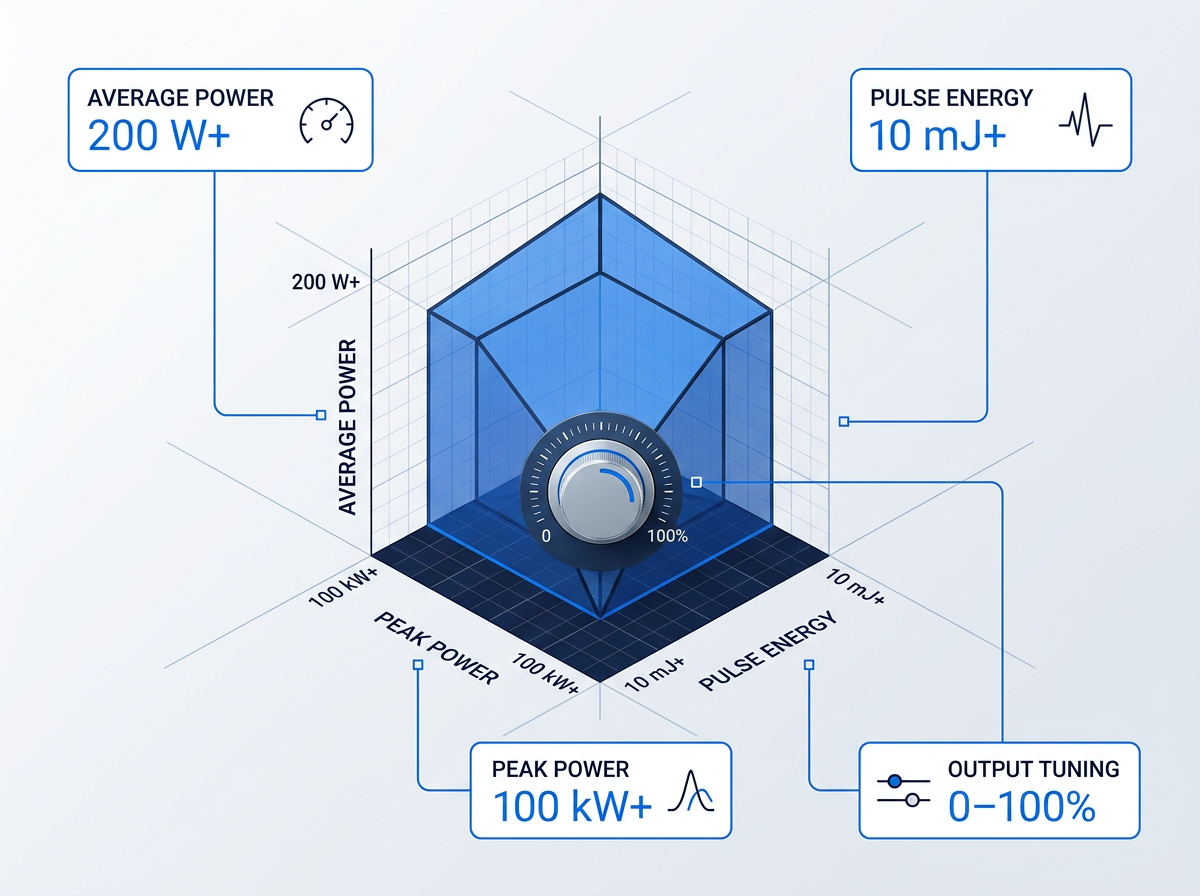
Output power, pulse energy and peak power are all configured per project. Builds range from low-power units to 200 W or more average power, with pulse energies above 10 mJ and peak powers above 100 kW — the figures established in the preceding section are targets, not fixed ceilings.
Output is continuously tunable from 0 to 100% of rated power. Submit your requirements to discuss what the build looks like for your application.
Regime and Cooling
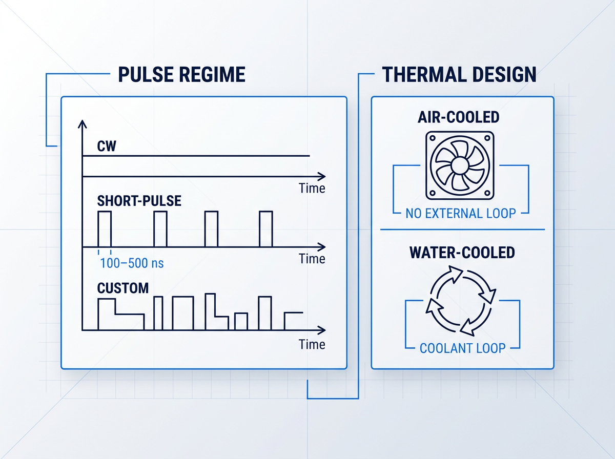
The pulse regime is specified per project: CW, short-pulse (e.g. 100–500 ns), or a custom configuration. The amplifier is built to the temporal profile your application requires.
Air-cooled as standard — no chiller or coolant loop required, which simplifies integration into your system. Water cooling is available as an option for builds where it is preferred.
Cable and Form Factor
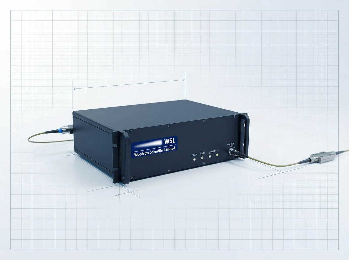
Delivery cable length and fibre termination are specified per project, so the amplifier connects directly to your system without adaptation or compromise.
The form factor and integration envelope are custom to each build. There is no fixed chassis to design around — the amplifier is sized and shaped to fit your system, whether that is a rack, a payload, or a bespoke housing.
Firmware and Platform
Control firmware and communication standards are custom per project. The amplifier is configured to speak your system's protocol, removing the integration overhead of bridging incompatible interfaces.
The fixed foundation: erbium-doped fibre gain medium, MOPA architecture, and a 1530–1625 nm wavelength window. These are the stable platform on which all configurable parameters sit — the physics and architecture that make the performance possible.
Why 1550 nm Is Safer
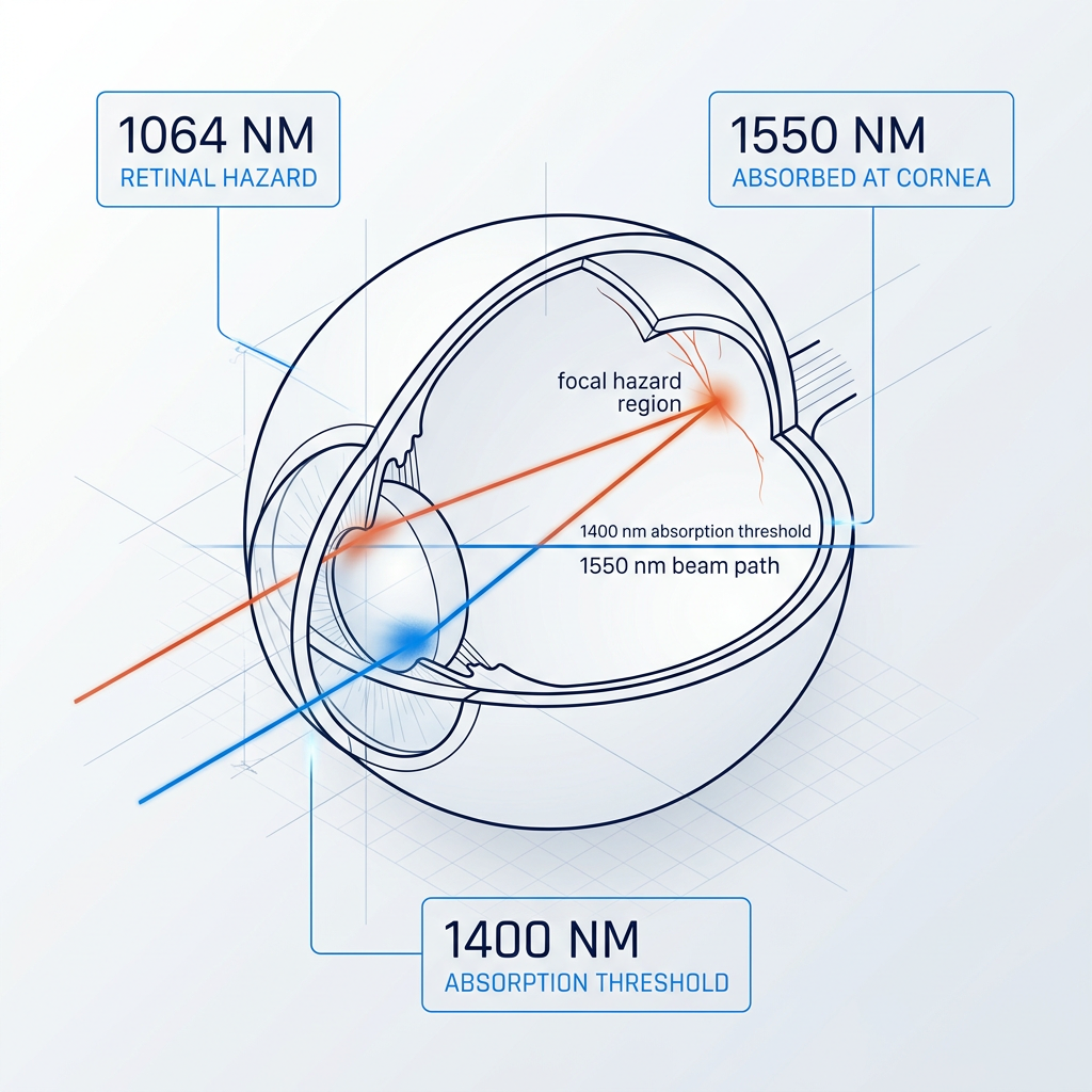
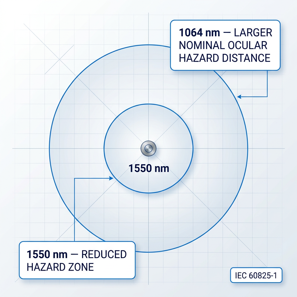
Wavelengths above 1400 nm are absorbed by the cornea and lens of the eye rather than transmitted to the retina — the tissue most vulnerable to permanent laser damage. At 1064 nm, collimated light reaches the retina and is focused to an intense spot; at 1550 nm, it does not. The Laser Institute of America confirms this distinction: 1400 nm marks the boundary of the retinal hazard region.
The result is a materially higher maximum permissible exposure at 1550 nm. WSL's Custom EDFA operates in this window, with reduced-hazard-zone builds available for safety-critical deployments.
Higher MPE, Smaller Hazard Zone
IEC 60825-1 is the international standard governing laser product safety classification and maximum permissible exposure (MPE). Because the MPE at 1550 nm is materially higher than at 1064 nm — a direct consequence of the retinal hazard boundary at 1400 nm — a 1550 nm system can operate at a given output power with a smaller nominal ocular hazard distance than an equivalent 1064 nm system. In practical terms: higher permissible operating power at a given hazard zone size, or a reduced hazard zone at equivalent power. Both translate to simpler site safety planning and easier compliance sign-off.
Built for Simpler Site Compliance
WSL offers reduced-hazard-zone builds of the Custom EDFA — a direct procurement and site-planning benefit for buyers operating in safety-conscious environments. A smaller exclusion zone means less floor area to control, fewer access restrictions, and a more straightforward path through safety sign-off and regulatory review.
For integration teams working within constrained facilities or tight compliance timelines, this simplifies the process of bringing a high-power fibre amplifier into service. The specific hazard zone achieved depends on power level and configuration; WSL's engineering team works through the details with each customer at specification stage.
Where Modern Photonics Converges
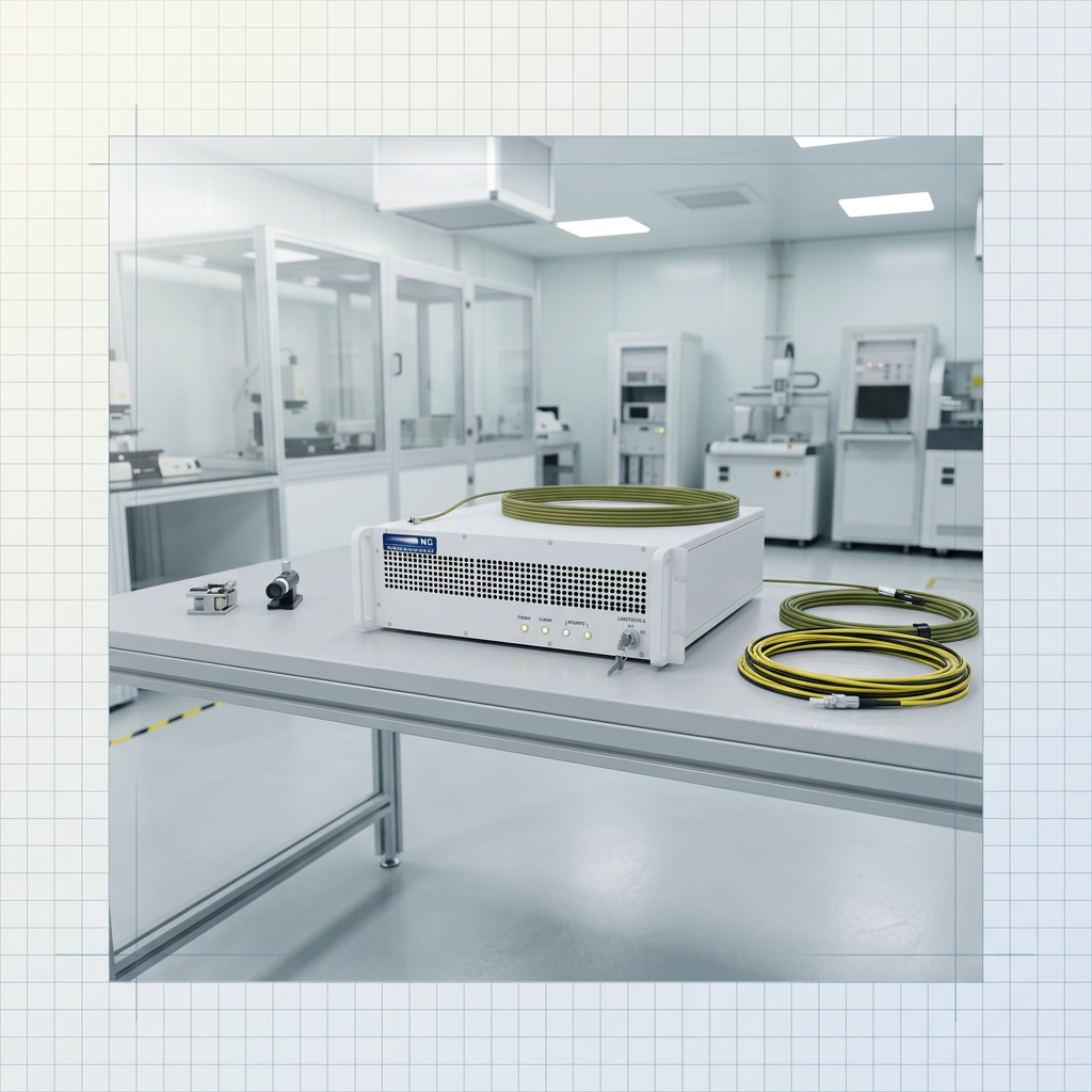
Three physics-driven reasons have made 1530–1625 nm the dominant window for high-power photonics. First, silica fibre reaches its loss minimum in this region — IEEE sources confirm standard single-mode fibre achieves around 0.18–0.20 dB/km near 1550 nm, enabling long-reach transmission. Second, 1550 nm sits within a well-established atmospheric transmission window, making it the standard choice for free-space optical links. Third, the global telecom industry built its C- and L-band component ecosystem — detectors, connectors, modulators, test equipment — around this window, so system integration draws on a deep, mature supply chain rather than bespoke parts.
Both Bands, One Cable
The Custom EDFA delivers both C-band (1530–1565 nm) and L-band (1565–1625 nm) from a single amplifier through a single cable. No second amplifier source is required, no second cable run, and no additional integration overhead to combine outputs from separate units.
For system architects, this is a straightforward engineering advantage: one procurement item, one interface, one support relationship. The full 1530–1625 nm window is available from a single point in the signal chain, simplifying both the bill of materials and the integration design.
Applications: Where the Custom EDFA Is Deployed
The Custom EDFA serves demanding application domains where high-power, eye-safe erbium-fibre amplification is the enabling technology — engineered to each programme's specific requirements.

LiDAR: Extended Range at Eye-Safe Power
Eye-safe 1550 nm permits higher pulse power than 905 nm sources, extending detection range. The MOPA architecture delivers short, high-peak-power pulses LiDAR ranging requires.

Free-Space Optical Communications (FSOC)
1550 nm sits in an atmospheric transmission window, compatible with telecom-grade components. High average power supports link budgets for ground-station uplink and beacon amplification.
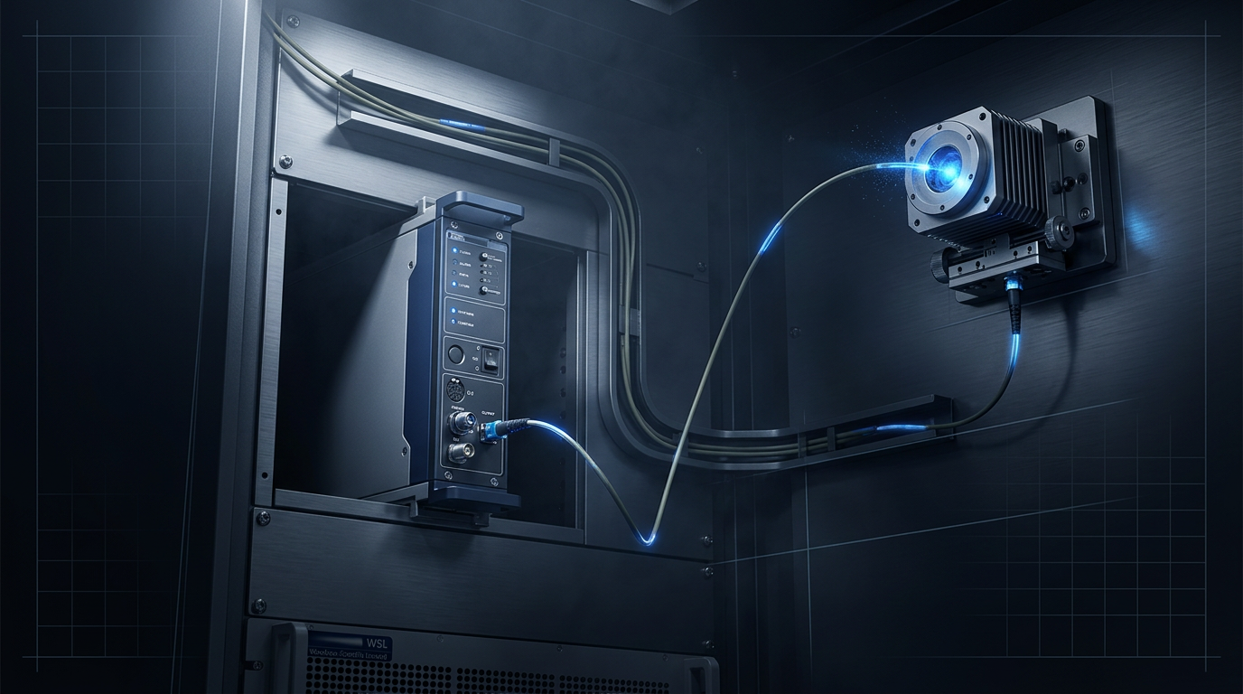
Defence and Directed-Energy Research
High average power, pulse energy, and peak power in the eye-safe band meet defence programme requirements. Configurable pulse regime and form factor enable platform integration.
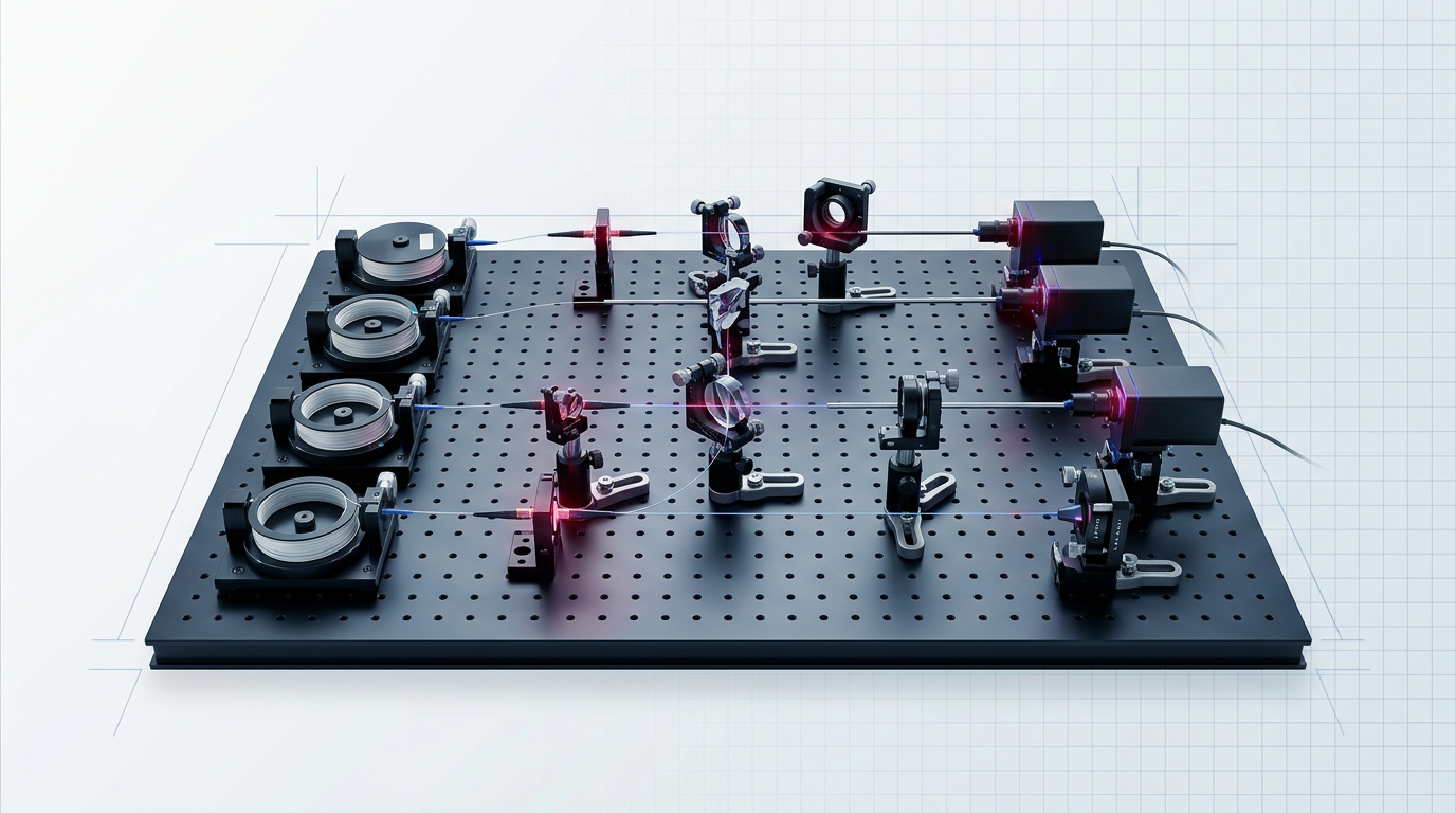
Quantum Sensing and Communications
The C-band 1550 nm window coincides with minimum loss in silica fibre — the established wavelength for QKD and quantum sensing over fibre infrastructure.
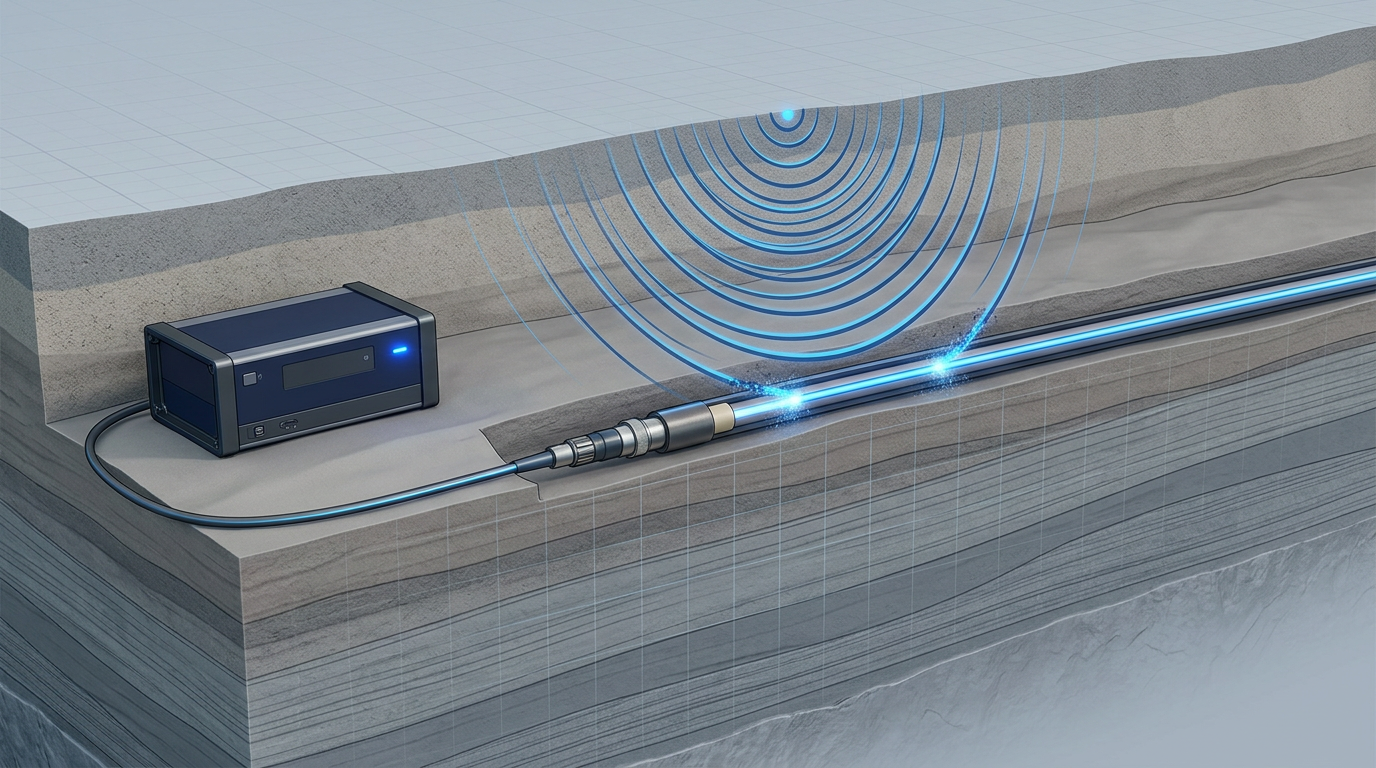
Distributed Acoustic Sensing and Fibre Sensing
EDFA pulse amplification is the standard interrogator architecture for DAS systems at 1550 nm. High peak power extends the sensing range along the fibre.
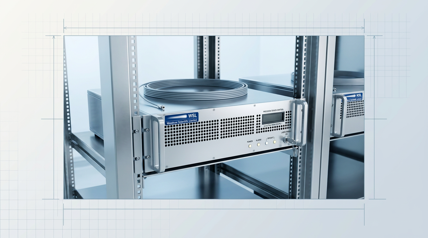
Remote Sensing and Scientific Instrumentation
Research platforms and atmospheric instruments require precise power control and spectral stability. Full 0-100% output control and configurable pulse regime serve these requirements.

OEM Laser System Integration
The Custom EDFA serves as the optical engine for OEM laser builds, configured to the integrator's form factor, firmware, and communication standards.
Ready to Specify Your High-Power Fibre Amplifier?
Download the EDF100 datasheet for concrete performance figures, or speak directly with WSL's engineering team about your application requirements and custom specification.

Where the EDFA Was Born
The erbium-doped fibre amplifier was first demonstrated in 1987 by researchers at the University of Southampton, according to IEEE. WSL is based in Southampton and works closely with the people who pioneered that technology.
This is not decorative geography. It is direct intellectual lineage — the same institution, the same field, the same city where the high-power fibre amplifier as a discipline began.
Deep Expertise, From the Source
WSL was founded in 2012 by a fibre-laser specialist holding a PhD from Southampton's Optoelectronics Research Centre, with 25+ years in the field. The team works closely with the people who pioneered erbium-fibre amplification.
Across a team of more than 20 specialists, WSL carries over 200 years of combined engineering experience — depth that bears directly on how each amplifier is specified, built, and supported.

Designed, Built, and Supported Here
Every Custom EDFA is engineered, assembled, qualified, and supported by the same WSL team in Southampton. When an integration issue arises, the engineers who answer are the engineers who built the unit.
Many EDFA suppliers are resellers or importers rather than manufacturers. With WSL, the engineering relationship sits with the team you deal with directly — not with an overseas manufacturer behind the supply chain.

10 Patents and Counting
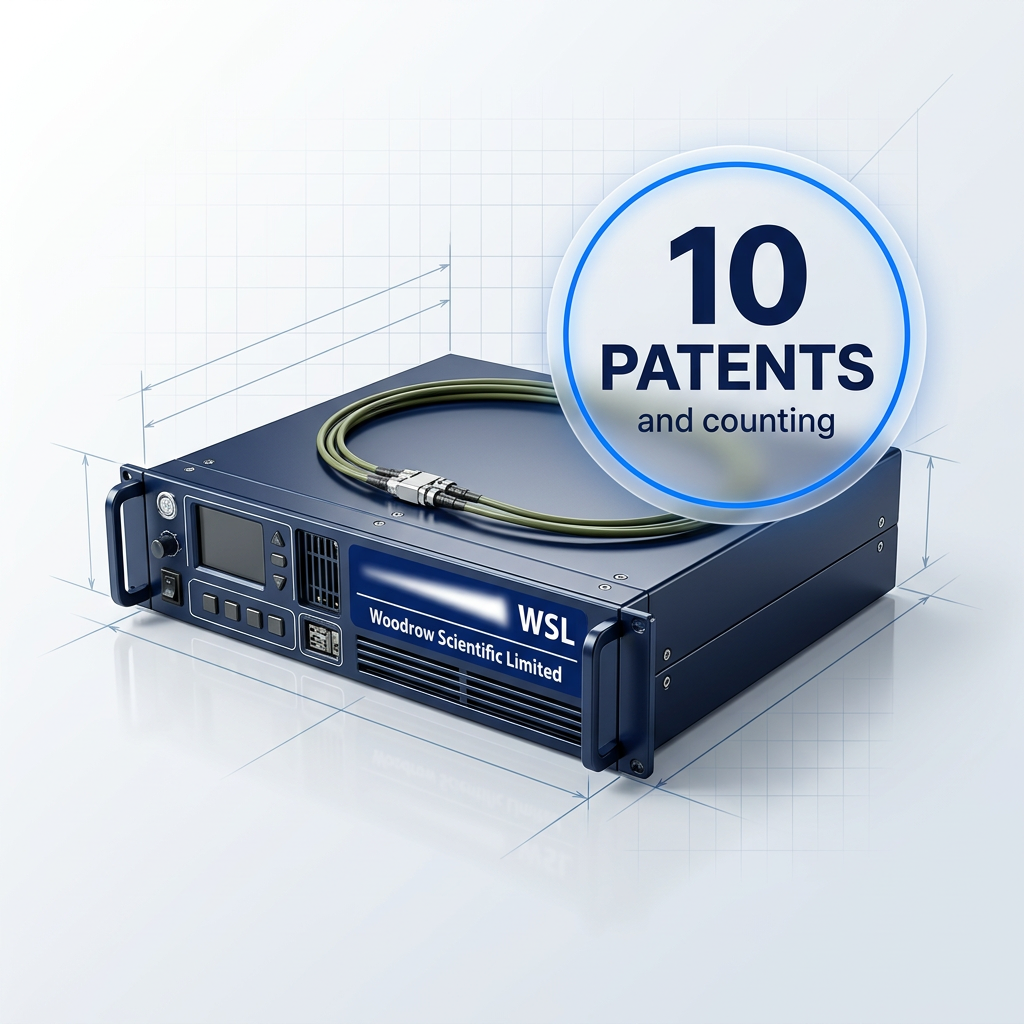
WSL holds 10 patents and counting — a direct measure of continuous, in-house innovation on the technology rather than resale of an established product.
The patent portfolio reflects the same engineering model that underpins every build: proprietary development, owned and controlled by the team that designs and manufactures the amplifier.
Direct from Southampton, Anywhere
Buyers in any country order direct from WSL in Southampton — no distributor layer, no intermediary, and a direct engineering relationship from first contact through to delivery and integration support.

CE and UKCA Certified for EU and GB Markets
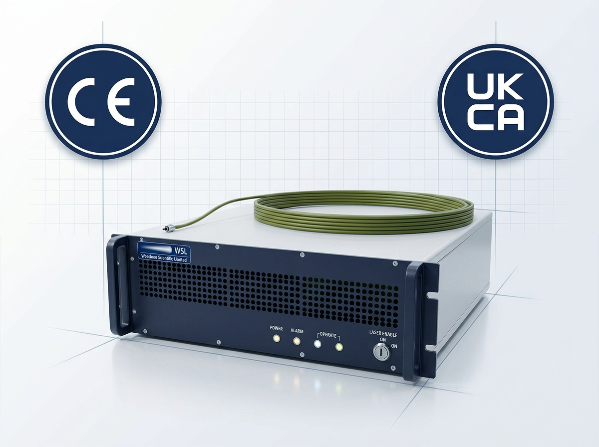
The Custom EDFA carries both CE marking and UKCA marking. Buyers placing the product on the EEA market or the GB market can proceed without a re-certification gap — both marks are held simultaneously.
WSL's engineering team supports every buyer from initial specification through to deployment and integration.
Frequently Asked Questions
Technical and procurement questions about the Custom EDFA, answered directly.
The Custom EDFA is quoted per project, not selected from a catalogue. Submit your requirements — operating band, output power, pulse regime, cooling preference, form factor, and firmware or communication standards — and WSL's engineering team evaluates the specification and responds with a tailored proposal. There is no fixed SKU to configure around; the amplifier is built to your application.
Yes. The specifications and applications shown on this page represent what WSL has built so far, not the boundary of what it can engineer. A requirement beyond the published figures — a different environment, an unusual power level, a non-standard form factor, a bespoke pulse regime — is assessed directly with the client by WSL's engineers. The right approach is to submit the requirement and discuss it; WSL does not rule requirements out in advance.
Yes. The 1530–1625 nm erbium-fibre window operates above the 1400 nm threshold, above which radiation is absorbed by the anterior ocular media — the cornea and lens — rather than reaching the retina. ICNIRP's laser guidelines confirm that 400–1400 nm is the retinal hazard region; wavelengths beyond it do not contribute to retinal exposure. The Custom EDFA therefore carries a materially higher eye-damage threshold than 1064 nm sources, and WSL offers reduced-hazard-zone builds for buyers where site safety classification is a procurement consideration.
Yes. Buyers in any country order direct from WSL in Southampton. There is no distributor layer — the buyer works directly with WSL's engineering team from first contact through to delivery and integration support.
A fiber amplifier boosts the power of an optical signal entirely in the optical domain, without converting it to electrical form. According to IEEE, an erbium-doped fiber amplifier (EDFA) operates by pumping a length of erbium-doped silica fiber with a laser diode at 980 nm or 1480 nm, exciting the erbium ions; incoming signal photons then stimulate those ions to emit coherent photons at the same wavelength, producing gain. In a MOPA architecture, a seed laser provides the signal and one or more amplifier stages raise it to the required output power. The standard operating window for erbium-doped amplifiers is 1530–1625 nm — covering the C-band (1530–1565 nm) and L-band (1565–1625 nm) — which coincides with the minimum-loss transmission window of silica fiber.
In the context of erbium-fibre amplifiers, high power means average output well above the typical commercial ceiling. Most EDFA builds operate at modest average powers; a high-power fibre amplifier is one engineered to deliver significantly greater output for demanding applications such as LiDAR, free-space optical communications, defence, and distributed sensing. WSL's Custom EDFA scales from low-power builds to 200 W or more average power, with pulse energies above 10 mJ and peak powers above 100 kW. Output is continuously tunable from 0 to 100% of rated power.