

Introduction
Satellites get the headlines. The ground stations that actually make them work rarely do.
Yet every command sent to an orbiting spacecraft, every image downloaded, every positioning signal broadcast — all of it depends on ground-based infrastructure that most coverage glosses over or ignores entirely.
This guide covers that infrastructure in full: what ground stations are, how their components function as an integrated system, how frequency bands are chosen, and how satellite control is maintained across a mission's lifetime.
It also looks at where the field is heading, as shared network services and optical communications begin reshaping what ground infrastructure looks like.
The treatment here assumes technical familiarity — this is written for engineers, space industry professionals, and serious students, not as a primer for the uninitiated.
TL;DR
Ground stations are not passive receivers — they are active, engineered systems on which every satellite mission depends for control, data return, and long-term viability. The field is also at a genuine inflection point: shared service models and optical communications are changing what ground infrastructure means for operators at every scale.
This article covers:

Ground stations and the broader ground segment
Core components and how they work together
Frequency bands and band-selection trade-offs
TT&C as the operational backbone of missions
Ground segment architecture: station to network
GSaaS and optical ground stations
What are satellite ground stations?
Every satellite mission has two halves: the spacecraft in orbit, and the ground-based infrastructure that keeps it operational. The second half rarely attracts the same attention as the first — yet without it, a satellite is an inert object, unable to receive commands, return data, or confirm its own health.
A satellite ground station is a terrestrial facility that communicates with, tracks, and exchanges data with orbiting spacecraft. Also referred to as an Earth station or ground Earth station, it is the primary physical interface between the ground and the spacecraft — not passive infrastructure, but an active, engineered system purpose-built to bridge the gap between Earth and orbit.
To understand where the ground station fits, it helps to draw the fundamental architectural boundary: the space segment comprises the orbiting spacecraft itself — its payload, onboard systems, and structure — while the ground segment encompasses all the ground-based elements used to collect and disseminate information from the satellite to the end user. The ground station is one element within the ground segment, not the whole of it.
The four primary elements of a ground system
NASA's ground systems taxonomy identifies four distinct elements that together constitute a complete ground system, each with a clearly defined function.
- Ground Stations: The telemetry, tracking, and command interface with the spacecraft — the antenna-and-RF terminal that communicates directly with the vehicle.
- Ground Networks: The communications infrastructure providing connectivity between multiple ground elements, linking stations, control centres, and storage systems.
- Control Centres: The management layer for spacecraft operations — where mission decisions are made, commands are generated, and data is processed.
- Remote Terminals: End-user interfaces for retrieving transmitted information for additional processing — the access points for data products and services.
These elements are interdependent: the ground station is the RF or optical terminal through which signals pass, the control centre is the decision-making layer that generates those signals, and the ground network is the connective tissue that carries data between them.
Within the control centre layer, two distinct functions are typically separated. The Mission Operations Centre (MOC) commands the spacecraft, monitors its performance, and requests and retrieves data as necessary. The Science Operations Centre (SOC) generates and disseminates science data products, and determines science operations to be relayed back to the MOC.
This distinction matters for understanding what a ground station actually is: it is the physical conduit through which the MOC and SOC reach the spacecraft — the RF or optical terminal that carries their instructions and receives the spacecraft's response. The ground station does not make mission decisions; it executes them.
Mission decisions originate in the MOC and SOC. The ground station's role is to be the reliable physical link that carries those decisions to the spacecraft and returns the spacecraft's data to the ground — a distinction that shapes how ground systems are designed, operated, and procured.
What do satellite ground stations do?
Every ground station, regardless of orbit, mission type, or size, performs three core functions: uplink, downlink, and tracking.
Uplink is the transmission of commands from the ground to the spacecraft — instructions that control its orientation, configure its instruments, or schedule its operations. Downlink is the reception of data flowing in the opposite direction: telemetry, housekeeping data, and mission payload data returning from the spacecraft to the ground. Tracking is the determination of the spacecraft's position and velocity, providing the navigational picture that underpins every other operation.
No satellite mission can operate without all three functions being performed reliably throughout its operational life — they are the operational heartbeat of the ground station.
Ground stations reach spacecraft through two fundamental communication architectures. In a Direct-to-Earth (DTE) arrangement, a ground station maintains point-to-point, line-of-sight contact with the spacecraft directly. In a space-relay arrangement, an intermediate relay satellite — such as NASA's Tracking and Data Relay Satellite System (TDRSS), a constellation of geosynchronous satellites — relays signals between the spacecraft and the ground, extending coverage well beyond what Earth geometry alone permits.
TDRSS, for instance, provides near-continuous communication between Earth and spacecraft in low Earth orbit, enabling data relay for missions that would otherwise lose contact whenever they pass out of view of a ground antenna. The architectural implications of DTE versus space-relay — coverage windows, network design, contact scheduling — are explored in detail later in this guide.
One further distinction is worth flagging at this stage: ground stations may operate in radio frequency (RF) wavelengths or in optical wavelengths, using laser beams rather than radio waves. These represent fundamentally different classes of ground station, with different hardware, atmospheric constraints, and performance characteristics. That distinction becomes operationally significant when examining frequency bands and is explored in depth in the section on optical ground stations.
With the purpose, architecture, and core functions of the satellite ground station established, the natural next question is: what physical and functional components make it work? That is where the next section begins.
Core components of a satellite ground station
A ground station is not a single device — it is a chain of interdependent subsystems, each performing a specific transformation on the signal as it travels from the satellite's radio waves to usable digital data, and back again in the opposite direction for transmit.
Understanding that chain is what separates a surface-level familiarity with ground stations from a working knowledge of how they actually perform: every design decision, from dish size to modem configuration, is a decision about one link in that chain and how it affects every link downstream.
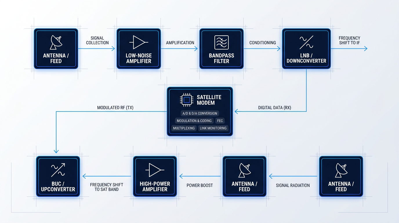
On receive, the chain runs from the antenna inward: the dish collects electromagnetic energy from the satellite, the feed converts it to a conducted RF signal, successive amplification and filtering stages condition it, a frequency converter translates it to a workable intermediate frequency, and the modem demodulates and decodes it into digital data handed off to the terrestrial network.
On transmit, the same chain runs in reverse: the modem modulates digital data onto an RF carrier, the converter upshifts it to the satellite's operating frequency, a high-power amplifier boosts it to the level needed to reach orbit, and the feed radiates it as a collimated beam via the dish.
The antenna and feed
The parabolic dish antenna is the most physically dominant element of any ground station, and its geometry is not incidental: the parabolic shape focuses all incoming energy onto a single point — the focal point — regardless of the angle at which parallel rays arrive, concentrating weak signals from distant spacecraft into a measurable electrical signal.
Antenna gain scales with aperture area, so a larger dish captures more signal energy and supports higher-gain links — critical when communicating with small satellites or spacecraft at the limits of their transmit power.
Operating frequency also shapes the aperture requirement: higher frequencies allow equivalent gain from a physically smaller dish, which is why Ka-band ground stations can be far more compact than their C-band counterparts for the same link performance — a trade-off explored in depth in the frequency bands section that follows.
At the focal point sits the feed — the interface between free-space propagation and the guided RF circuit. On receive, the feed converts the electromagnetic waves concentrated by the dish into a conducted electrical signal; on transmit, it does the reverse, radiating a conducted RF signal as a directed beam shaped by the reflector.
Signal conditioning: LNA, filtering, and HPA
The signal arriving at the feed after a journey from orbit is extraordinarily weak — often only a few picowatts of power. The low-noise amplifier (LNA) is the first active component in the receive chain, and its job is to amplify this signal before it degrades any further.
The LNA's noise figure is the single most consequential specification in the receive chain: any noise introduced at this first stage is amplified by every subsequent stage, so a poorly specified LNA raises the noise floor of the entire system, not just its own output.
Immediately after the LNA, bandpass filtering rejects out-of-band interference, ensuring that only the frequencies of interest continue down the chain — this protects subsequent stages from intermodulation products and adjacent-band interference that would otherwise degrade signal quality.
On the transmit side, the equivalent of the LNA is the high-power amplifier (HPA): positioned at the end of the transmit chain, it boosts the modulated signal to the power level required to close the uplink to the satellite, compensating for the free-space path loss across hundreds or thousands of kilometres.
Up/down converters: BUC and LNB
Satellite signals operate at frequencies where cable losses over even short runs would be unacceptable. Block converters solve this by translating the signal between the satellite's operating frequency and a lower intermediate frequency (IF) — typically in the L-band range around 950–2150 MHz — that can travel over standard coaxial cable with manageable loss.
On receive, the Low Noise Block downconverter (LNB) combines the LNA and frequency downconversion in a single outdoor unit mounted at the feed, shifting the satellite-frequency signal down to IF for the cable run to the indoor modem.
On transmit, the Block Up-Converter (BUC) takes the modem's IF output and upshifts it to the satellite's operating frequency before it reaches the HPA and feed.
Placing the LNB and BUC at the feed — rather than indoors — minimises the length of cable carrying the full satellite-frequency signal, which directly reduces noise and insertion loss; indoor placement is cheaper and easier to service, but the performance penalty grows with cable length and operating frequency.
The satellite modem
The satellite modem is substantially more complex than its terrestrial counterpart — it is the signal-processing intelligence of the ground station, responsible for translating between the digital world of IP data and the analogue world of modulated RF carriers.
- A/D and D/A conversion: Converts the incoming analogue IF signal to digital samples on receive, and digital data back to an analogue carrier on transmit.
- Modulation and coding: Defines how bits are mapped to the waveform — schemes such as QPSK, 8PSK, and 16APSK trade spectral efficiency against noise tolerance.
- Forward error correction (FEC): Adds structured redundancy via turbo codes or LDPC so the receiver can recover data even when the link is degraded by noise.
- Multiplexing: Manages multiple channels or users on a single carrier using time-division or frequency-division techniques.
- Link performance monitoring: Continuously measures Eb/N0, signal-to-noise ratio, and bit error rate to characterise link health in real time.
The modem marks the definitive boundary between the RF domain and the digital domain: on receive, its output is a stream of digital data ready for the terrestrial network; on transmit, its output is a modulated RF carrier ready for frequency conversion and amplification.
Tracking and drive systems
For geostationary satellites, the antenna is pointed once during installation and remains fixed. For LEO and MEO satellites, the antenna must physically follow the spacecraft across the sky during each pass, which is the job of the azimuth/elevation (Az/El) mount: a two-axis drive system that rotates the dish in the horizontal plane (azimuth) and tilts it above the horizon (elevation) under continuous software control.
Pointing accuracy is not a secondary concern — at high frequencies, the antenna beam is narrow enough that even a small tracking error moves the satellite outside the beam, causing a direct and immediate loss of link margin. The drive system's motors, gearing, and position encoders must maintain alignment to within a fraction of the beamwidth throughout the pass.
For GEO-only installations, a polar mount offers a simpler single-axis alternative: one rotational axis aligned with the Earth's polar axis allows the antenna to sweep the entire geostationary arc with a single motor, though this geometry does not suit non-GEO tracking.
Radome: protection with a trade-off
A radome is a microwave-transparent enclosure — typically constructed from fibreglass or PTFE-coated fabric — that surrounds the antenna and outdoor equipment to protect them from wind loading, ice accumulation, rain, and UV degradation.
The protection comes at a cost: the radome material introduces a small but real insertion loss that must be accounted for in the link budget, and this penalty increases with operating frequency. Not every ground station uses one — smaller or sheltered installations often operate without a radome — but for large dishes in exposed coastal, high-altitude, or high-wind environments, the pointing stability and equipment longevity benefits outweigh the signal loss.
Terrestrial interconnect and the software layer
At the far end of the receive chain, the modem hands off digital data to the terrestrial network via the terrestrial interconnect — which may be a router for IP data, a multiplexer combining multiple data streams, or a video codec for broadcast applications, depending on the mission.
This handoff point is where the space link meets terrestrial infrastructure, and the ground station's value is ultimately constrained by the quality of the network it connects to. The broader architecture of how ground stations, control centres, and ground networks interoperate is covered in the Ground Segment Architecture section.
Sitting across the entire hardware chain is the software layer. Software-defined radio (SDR) architectures replace fixed-function RF hardware with general-purpose or FPGA-based processors running configurable software — waveform generation, modulation, demodulation, and filtering all become software parameters rather than hardware circuits, enabling a single physical installation to be reconfigured for different frequencies, modulation schemes, or missions without replacing equipment.
Alongside SDR, antenna-pointing software provides the integrating intelligence for the drive system: it ingests orbital element data (typically in TLE format), computes the satellite's position in real time, and commands the Az/El mount to track it through acquisition, pass, and handover — functions that no amount of hardware precision can substitute.
Noise introduced at the LNA is amplified by every stage that follows it. No amount of gain added later can recover signal quality lost at this first stage — which is why LNA noise figure is the primary specification when evaluating receive chain performance.
With the component chain established, the next dimension of ground station design is frequency band selection: the choice of operating frequency affects antenna aperture requirements, converter hardware, atmospheric propagation losses, and the modulation schemes the modem can practically support — all of which are examined in the section that follows.
Frequency Bands in Satellite Communications
Every frequency choice in satellite communications is a trade-off, and understanding that trade-off is what makes sense of everything from a small CubeSat's TT&C link to a high-throughput internet satellite: higher frequencies deliver wider bandwidth and allow smaller antenna apertures, but they suffer greater atmospheric attenuation and rain fade; lower frequencies punch through weather reliably but carry limited data and are increasingly congested.
This is not merely an engineering preference — it is a structural constraint baked into physics and compounded by decades of spectrum use, which is why the choice of operating band shapes a mission's antenna size, link reliability, regulatory burden, and ultimately its data throughput ceiling.
From L-band to optical: the principal frequency bands
The table below maps the principal satellite communications bands against the dimensions that matter most in practice: frequency range, bandwidth class, atmospheric sensitivity, and primary uses.
| Band | Frequency Range | Bandwidth Class | Atmospheric Sensitivity | Primary Uses |
|---|---|---|---|---|
| L-band | 1–2 GHz | Narrow | Very low — excellent weather resilience | GPS, satellite phones, maritime and aviation tracking |
| S-band | 2–4 GHz | Low–moderate | Low — good atmospheric penetration | TT&C for near-Earth missions, mobile satellite services, deep-space telemetry |
| C-band | 4–8 GHz | Moderate | Low rain fade, wide coverage | Satellite TV broadcasting, enterprise VSAT, long-distance telephony |
| X-band | 8–12 GHz | Moderate | Low–moderate; protected allocation | Military SATCOM, SAR imaging, government TT&C |
| Ku-band | 12–18 GHz | High | Moderate rain fade | Satellite TV (DTH), in-flight connectivity, maritime broadband |
| Ka-band | 27–40 GHz | Very high | High — significant rain fade above 10 GHz | HTS internet, 5G satellite backhaul, cloud access, enterprise broadband |
| Free-space optical | ~193–300 THz (infrared) | Effectively unlimited | High — atmospheric turbulence and cloud outages | High-throughput inter-satellite and ground links; no ITU licensing required |
Comparison of principal satellite frequency bands across frequency range, bandwidth, atmospheric sensitivity, and primary uses — enabling readers to see the trade-off axis play out across all bands simultaneously.
Reading the table from top to bottom, the trade-off axis plays out exactly as physics predicts: atmospheric sensitivity climbs steadily as frequency rises, while bandwidth capacity grows in parallel — each band is essentially a different point on the same curve between resilience and throughput.
For a ground station engineer, that curve translates directly into design decisions: a mission requiring continuous, weather-independent contact — GPS, a maritime distress beacon, an aviation safety link — belongs at L-band, where signal loss through rain is negligible and coverage is near-universal.
S-band sits one step up: stable, with good atmospheric penetration and data rates sufficient for spacecraft command and health monitoring, which is why it became the dominant band for TT&C on near-Earth missions and remains so today across both civil and government programmes.
The James Webb Space Telescope illustrates the dual-band pattern common to high-complexity missions: S-band handles command uplinks (up to 16 kbps) and engineering telemetry downlinks (up to 40 kbps), while Ka-band at 26 GHz carries science data at up to 28 Mbps — a data rate that would take many days to achieve over S-band alone.
C-band was the workhorse of satellite television broadcasting and enterprise VSAT for decades, valued for its low rain fade and wide footprint coverage — but its available spectrum is narrow, and congestion has become a growing operational reality as the number of satellite operators competing for the same allocation has multiplied.
X-band occupies a distinct position in the landscape: it is allocated specifically for government and military use, which is why it remains less congested than commercial bands despite its attractive combination of moderate bandwidth and good stability — military SATCOM, synthetic aperture radar imaging, and government TT&C all depend on this protected status.
Ku-band brought a practical advantage that accelerated commercial adoption: for the same antenna aperture, Ku delivers roughly 7 dB more gain than C-band, which means smaller dishes can close the link — enabling the proliferation of in-flight connectivity terminals, maritime broadband systems, and consumer direct-to-home services.
At Ka-band, the bandwidth available for high-throughput satellite internet, 5G backhaul, and cloud access is substantial — but the atmospheric penalty is no longer a design footnote; it is a primary engineering problem, requiring operators to deploy fade mitigation techniques including adaptive coding and modulation (ACM), uplink power control, and site diversity to maintain availability targets.
The NASA Advanced Communications Technology Satellite programme demonstrated that fades of 20 dB or larger occur at least 0.1% of the time at Ka-band in subtropical rain zones — a figure that forces system designers to either budget large power margins or deploy active mitigation, adding cost and complexity that simply does not exist at C-band or below.
Below S-band, extensive use has led to crowding and licensing challenges. As NASA's own State of the Art assessments document, the shift toward higher bands — S, X, Ka — is driven not by preference but by necessity: lower bands are saturated, and Ka-band is now NASA's desired band for future small satellite missions.
Beyond Ka-band lies free-space optical (FSO) communications, which sidesteps the RF spectrum entirely by using infrared laser wavelengths: bandwidth is effectively unlimited, there is no ITU frequency coordination or licensing requirement, and the narrow beam is inherently resistant to interference.
The primary challenge for optical links is the atmosphere itself — cloud cover and turbulence can interrupt or degrade the beam entirely, which is why RF is currently considered complementary rather than replaceable for missions that require uninterrupted contact under all weather conditions; but for high-throughput scenarios where data volume matters more than continuous availability, optical is where the industry is heading, and a later section of this guide examines how ground stations are being built to support it.
Spectrum governance and band selection in practice
The ITU (International Telecommunication Union) allocates frequency bands and associated orbital positions under the Radio Regulations — an intergovernmental treaty that governs how spectrum and orbit resources are shared between nations and operators worldwide.
Before a satellite operator can use a frequency assignment, the relevant national administration must complete an ITU coordination process: submitting advance publication information, coordinating with other administrations whose systems could be affected, and notifying the assignment for recording in the Master International Frequency Register — a process that can take up to seven years from initial filing to operational status.
This is not a bureaucratic formality; it is a genuine overhead with real cost and timeline implications, and it applies to every RF band in the table above, from L through Ka.
Free-space optical links fall outside the radioelectric spectrum as defined by the Radio Regulations and are therefore not subject to this coordination regime — a distinction confirmed by the ITU itself, and one that makes optical increasingly attractive beyond its raw bandwidth advantage.
In practice, small satellite missions typically start with UHF or S-band for early operations and TT&C, then use X or Ka-band for payload data downlink depending on mission complexity and data volume requirements; the documented shift toward higher bands across the industry reflects both growing data-rate demands and the saturation of lower allocations.
With the frequency landscape established — the trade-offs, the bands, the governance, and the optical horizon — the next section examines TT&C (telemetry, tracking, and command) in depth: the operational backbone of satellite control, and the reason S-band's resilience and atmospheric penetration make it the natural home for these critical links.
TT&C: Telemetry, Tracking, and Command
Strip away a satellite's ability to receive commands, report its health, or be located in space, and you no longer have an operational spacecraft — you have an uncontrolled object in orbit. The function that prevents this outcome is TT&C: the foundational control relationship between a ground station and its spacecraft, covering telemetry, tracking, and command.
TT&C is not a housekeeping afterthought sitting alongside the mission's real work. It is the operational backbone that makes every other function possible — without it, no instruction reaches the spacecraft and no health data reaches the operators.
- Telemetry: Housekeeping data downlinked from the spacecraft — reporting power, thermal state, attitude, and propulsion status so operators can confirm the satellite is functioning correctly.
- Tracking: Determining the satellite's position and velocity by measuring the round-trip propagation delay of a ranging signal and the Doppler shift of the carrier frequency.
- Command: Uplinked instructions from the ground to the spacecraft platform — reconfiguring subsystems directly or uploading time-tagged sequences for pre-planned execution.
An important boundary to establish: TT&C concerns the spacecraft platform — its health and controllability. Payload Data Transmission (PDT), by contrast, carries the mission's scientific or commercial output: Earth observation imagery, relay traffic, sensor measurements.
The two subsystems are architecturally separate, using different antennas, different link configurations, and different ground station equipment. PDT typically operates at far higher data rates than TT&C requires. Keeping this distinction clear is essential to understanding why TT&C is treated as a distinct, mission-critical function rather than just another data link.
Telemetry: From Spacecraft Sensors to the Ground
Telemetry data does not arrive at the ground as a raw sensor dump. The spacecraft's Command and Data Handling (C&DH) system — sometimes referred to as the Command and Data Management Unit (CDMU) — collects housekeeping parameters from across the platform: temperatures, voltages, current draws, attitude sensor readings, and command execution status.
This data is assembled into structured transfer frames and passed to the transponder for downlink. The result is a packetised, multiplexed data stream — not raw sensor values — which is what the ground station's demodulation and processing chain is designed to receive and decode.
Instructions to platform and payload units flow in the opposite direction over the on-board data bus, with the OBDH bus serving as the internal interface between the data handling system and the spacecraft's subsystems.
Tracking and Ranging: Locating the Spacecraft
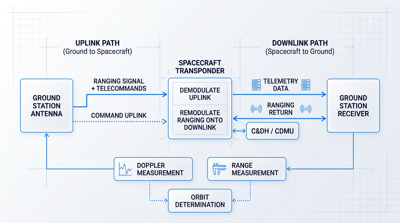
The transponder plays a central role in ranging. It demodulates the ranging signal embedded in the uplink carrier and remodulates it onto the downlink. The ground station measures the round-trip propagation delay to derive range; Doppler offset and Doppler rate yield radial velocity.
Together, these measurements feed orbit determination — the mathematical process of computing the spacecraft's state vector (position and velocity). Without accurate orbit determination, antenna pointing cannot be planned and manoeuvre execution cannot be verified.
Telecommands fall into two broad categories. Direct commands immediately reconfigure a spacecraft subsystem — switching a unit on or off, or changing an operating mode — and take effect as soon as they are decoded on board.
Stored commands are uploaded as time-tagged sequences to on-board memory, where they are held for execution at a pre-planned future time. This capability is particularly important for satellites with limited ground contact windows, where real-time commanding is not always possible.
TT&C Architecture: The Redundancy Principle
Standard TT&C hardware architecture is built around full redundancy. The ESA Bulletin describes the typical configuration: two low-gain antennas providing hemispherical coverage, two transponders, and two command decoders — all cross-strapped to ensure that a single unit failure cannot sever the control link.
The low-gain antennas are sized for hemispherical coverage precisely because attitude cannot be guaranteed during an anomaly. A spacecraft that has entered safe mode may be tumbling or in an unexpected orientation; the low-gain antenna must be able to receive a command regardless of which way the spacecraft is pointing.
A single-string TT&C system — one transponder, one antenna, one decoder — is a mission risk no operator accepts. TT&C is the last line of recovery if a spacecraft enters safe mode, so full hardware redundancy is the baseline, not an upgrade.
The Venus Express spacecraft illustrates this architecture in practice. Its TT&C subsystem was built around two redundant dual-band transponders, with two Low Gain Antennas providing omnidirectional S-band coverage for use during launch, early operations, and emergencies.
The mission used S-band and X-band TT&C across three ESA ground stations: Cebreros (Spain) served as the primary station throughout all mission phases; New Norcia (Australia) supported Venus Orbit Insertion and radio science campaigns; and Kourou (French Guiana) provided S-band coverage during the Launch and Early Operations Phase. Only the S-band uplink and downlink were used during LEOP, with X-band taking over for the cruise and routine science phases.
As covered in the frequency bands section, S-band is the standard TT&C band for near-Earth missions. The ESA Bulletin confirms that S-band allows data rates up to approximately 1 Mbit/s — sufficient for housekeeping telemetry and command uplink on Earth-orbiting missions up to and including GEO. X-band and Ka-band serve deep-space missions where greater link precision is required.
With TT&C established as the foundational control relationship between ground and spacecraft, the natural next question is how multiple stations are coordinated into a coherent network — managing coverage across geographies, dividing operational responsibilities, and ensuring the full ground segment functions as a system. That is the subject of the next section.
Ground Segment Architecture: From Station to System
A single ground station is a remarkable piece of engineering — but it is only one node in a much larger system. The real capability of a ground segment emerges from how stations, networks, control centres, and user terminals are layered together, and from the engineering disciplines that determine whether the whole system can reliably close a link with a spacecraft hundreds or thousands of kilometres overhead.
Layers of the Ground Segment
NASA's ground systems architecture identifies four primary elements: ground stations, ground networks, control centres, and remote terminals — each performing a distinct function in the chain from spacecraft to end user.
The ground station is the antenna-and-RF interface: it receives telemetry, transmits commands, and provides ranging data, but it does not interpret what it receives.
The ground network connects these stations to one another and to the control centres — providing live connectivity for commands and telemetry, and temporarily storing data for retrieval when a direct connection is not available.
The Mission Operations Centre (MOC) is the engineering intelligence behind the antenna: it commands the spacecraft, monitors its health, and requests data as needed. The Science Operations Centre (SOC) sits alongside it, generating and disseminating science data products and determining what science operations should be relayed to the MOC.
This distinction matters because it explains why "ground station" and "ground segment" are not synonyms. The station is the physical interface; the MOC and SOC are the operational brain. A mission could share a ground station with another operator while maintaining entirely separate MOC and SOC facilities.
Direct-to-Earth vs Space Relay
Two fundamental architectures exist for getting data from a spacecraft to the ground. Direct-to-Earth (DTE) is the simpler of the two: a point-to-point, line-of-sight link between the satellite and a ground station, with no intermediate node.
DTE is straightforward and cost-effective, but it is geometrically constrained — the satellite must be above the horizon at a ground station for contact to be possible, and for a LEO spacecraft that window is brief.
Space relay extends coverage by routing signals through intermediate relay satellites in geosynchronous orbit. NASA's Tracking and Data Relay Satellite System (TDRSS) is the canonical example: relay satellites positioned in GEO act as bent-pipe repeaters, providing contact with LEO spacecraft even when no ground station has line of sight to the vehicle.
For missions requiring near-continuous contact — crewed vehicles, time-critical science instruments, or spacecraft undergoing anomaly recovery — DTE from a single station is simply insufficient. Space relay, or a geographically distributed ground network, becomes a mission requirement rather than a design preference.
Contact Windows and Coverage Geometry
A contact window is the period during which a satellite is above the minimum elevation angle of a ground station and a usable link can be established. For LEO satellites at typical altitudes of 400–700 km, a single overhead pass lasts only around 5–10 minutes before the spacecraft drops below the horizon.
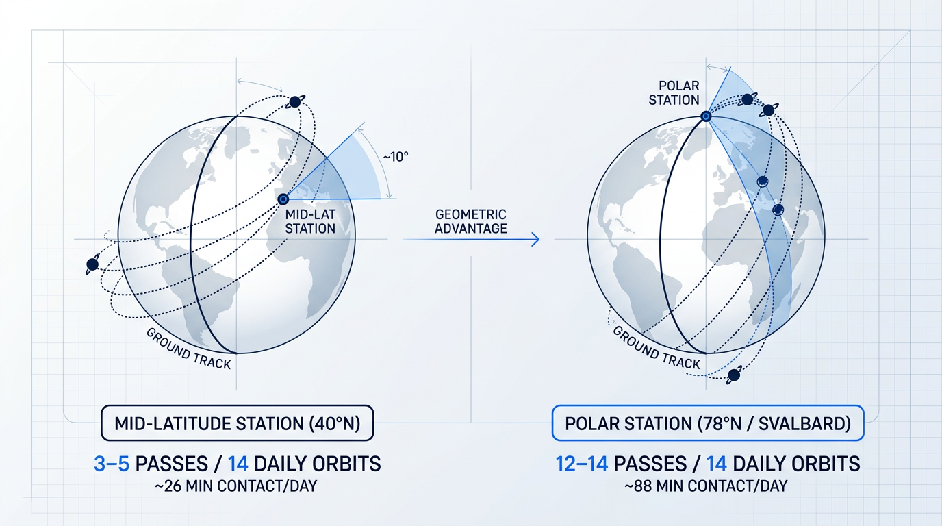
The geometry is unforgiving: a LEO satellite completes roughly 14–15 orbits per day, but a mid-latitude ground station may only see 3–5 of those passes, and not every pass reaches a high enough elevation angle to support the full link margin.
Polar stations offer a structural geometric advantage for polar-orbiting satellites. Because a polar orbit sweeps across high latitudes on every revolution, a station positioned near the pole lies beneath nearly every pass the satellite makes.
The Svalbard station at 78°N is the clearest illustration of this principle: its location means it can provide contact on all 14 daily passes of a polar-orbiting satellite — something no mid-latitude station can achieve. ESA's Kiruna station at high northern latitude similarly provides visibility for 10 to 12 out of 14 daily orbits for LEO missions.
Antarctica plays the complementary southern role. NASA's SMAP mission, in a near-polar orbit at 685 km, uses the McMurdo station in Antarctica alongside Svalbard and two northern-hemisphere stations to maximise daily coverage minutes — with Svalbard averaging over 88 minutes of contact per day compared to roughly 26 minutes at the mid-latitude Wallops station in Virginia.
ESTRACK: A Worked Example in Network Design
ESA's ESTRACK network illustrates how a real agency distributes its ground stations to achieve the coverage and redundancy a full mission lifecycle demands. The core network spans multiple continents, with stations at Kourou (French Guiana), Malindi (Kenya), Maspalomas and Villafranca (Spain), Redu (Belgium), Kiruna (Sweden), Perth and New Norcia (Australia).
The logic of this distribution is not arbitrary. Kourou, Perth, and Villafranca are positioned to provide good coverage of the geostationary transfer orbit arc — the trajectory a satellite follows in the critical hours after launch — making them the primary stations for LEOP (Launch and Early Orbit Phase) support.
During LEOP, near-continuous contact is essential: solar panels must be deployed, attitude control established, and onboard systems verified under strict time constraints. ESA typically enlists up to half a dozen stations — including partner-network facilities — to ensure commanding passes are available throughout this phase.
Kiruna, at high northern latitude, becomes the prime station for routine LEO operations once LEOP is complete. The Svalbard station (operated by KSAT as part of the augmented network) fills the orbits not visible from Kiruna, so together the two stations provide near-complete daily coverage for polar-orbiting missions.
New Norcia's 35-metre deep-space antenna addresses an entirely different mission phase: interplanetary cruise and science operations, where signals must travel hundreds of millions of kilometres and every fraction of a decibel of antenna gain matters. ESA designed its three 35-metre deep-space antennas — at New Norcia, Cebreros (Spain), and Malargüe (Argentina) — approximately 120° apart in longitude, so that as Earth rotates, at least one station always has the spacecraft in view.
The ESTRACK example makes the design principle concrete: no single station can serve all mission phases or all orbital regimes. Geographic spread, antenna aperture, and latitude are all deliberate engineering choices, not historical accidents.
The Link Budget: Closing the Link
Before any antenna is pointed or frequency assigned, a ground segment designer must answer a fundamental question: will the received signal be strong enough to decode reliably? The tool for answering that question is the link budget.
A link budget is an end-to-end accounting of all the power gains and losses between transmitter and receiver. It starts with transmitted power and antenna gain on the spacecraft side, then subtracts free-space path loss (which grows with the square of distance and linearly with frequency), atmospheric attenuation, and any pointing or polarisation losses.
On the receive side, the ground station's antenna gain and noise figure determine how well the system can pull the signal out of the noise floor. The result is a signal-to-noise ratio estimate at the receiver.
"Closing the link" means the calculated SNR exceeds the minimum required for the chosen modulation and coding scheme — with margin to spare. A link margin of 3 dB is the standard rule of thumb for S- and X-band missions: it represents the buffer against signal fluctuations, pointing errors, and unexpected propagation losses that real operations inevitably produce.
The key variables that feed a link budget are transmit power, antenna gain (both spacecraft and ground), free-space path loss, atmospheric attenuation, noise figure, and the required SNR for the target data rate. Adjusting any one of these shifts the margin — which is why ground station antenna size, spacecraft transmitter power, and frequency band are all intimately connected decisions.
Operational Challenges
Real ground segments operate under constraints that go well beyond the clean geometry of orbital mechanics. Four deserve particular attention.
- Rain fade at Ka-band: Higher frequencies are more susceptible to absorption and scattering by atmospheric water. At Ka-band, rain attenuation can reach 40–50 dB in worst-case conditions, making fade mitigation techniques operationally necessary.
- Interference: Adjacent satellite signals and terrestrial systems share congested spectrum. Broadcasting-satellite emissions can spill into fixed-satellite bands, and orbital crowding makes co-channel interference a real operational risk.
- Spectrum licensing overhead: ITU coordination requires advance publication, bilateral coordination, and formal notification — a process that can span years before a frequency assignment achieves international recognition.
- Propagation latency: GEO round-trip signal delay is 239–278 ms — a direct consequence of the 35,786 km orbital altitude and the finite speed of light. LEO latency is substantially lower, typically 20–40 ms.
Rain fade is the most acute atmospheric constraint at higher frequency bands. The physics is straightforward: millimetre-wave signals interact with raindrops at a scale comparable to their wavelength, causing both absorption and scattering. Systems operating at Ka-band must budget for this degradation explicitly and often employ site diversity or adaptive coding to maintain availability.
The GEO latency figure of 239–278 ms deserves a brief physical explanation. At the speed of light (approximately 300,000 km/s), a signal travelling 35,786 km to GEO and back covers roughly 71,572 km — producing a one-way delay of about 120 ms and a round-trip of just under a quarter of a second. For real-time commanding or interactive voice, this delay is perceptible and constraining; for bulk data transfer it is manageable.
Spectrum licensing adds a less visible but substantial operational burden. Obtaining ITU frequency coordination for a new satellite network involves a multi-step process — advance publication, coordination with affected administrations, and formal notification — that the ITU's own regulations require to be completed no later than seven years after advance publication. For operators planning new missions, this timeline is a hard architectural constraint.
Teleports and Gateway Stations
Not every ground station is a mission control facility. Teleports and gateway stations serve a different function: they are the terrestrial interface where satellite capacity meets ground networks.
A gateway station aggregates traffic between the satellite and the terrestrial backbone — routing data to internet exchange points, public switched telephone networks, or cable TV distribution infrastructure. The Hylas-1 mission illustrates the model: gateway stations at Goonhilly and Land's End in Cornwall connected Ka-band satellite capacity to the internet backbone, with a Network Operations Centre in London coordinating traffic.
The distinction between a TT&C station and a gateway is architectural: TT&C stations serve the spacecraft operator, while gateways serve the end-user service. A commercial broadband satellite may have its spacecraft controlled from one set of facilities while its user traffic flows through an entirely separate gateway network.
The Svalbard station at 78°N can contact a polar-orbiting satellite on all 14 of its daily passes. A mid-latitude station at 38°N — such as Wallops, Virginia — averages only 3.3 contacts per day for the same orbit. Station latitude is one of the highest-leverage variables in LEO ground network design.
The cumulative weight of these constraints — coverage gaps, contact window management, link budget engineering, spectrum licensing timelines, and the geographic and capital cost of building a distributed network — is precisely what has driven the industry to rethink how ground segment access is provisioned. That structural shift is what the next section examines.
Ground Segment as a Service: Shared Infrastructure
Building and operating a dedicated ground segment has historically meant capital expenditure, site acquisition, spectrum licensing, and a permanent operations team — commitments that made sense for large institutional programmes but placed serious barriers in front of smaller operators and new entrants. Ground Segment as a Service changes that calculus structurally, not just commercially.
The NASA 2022 State of the Art Ground Data Systems report defines GSaaS precisely: a managed service that enables customers to communicate with, downlink data from, and process data from their satellites on a pay-per-use basis, without needing to build their own ground station infrastructure.
The structural parallel to cloud computing is direct and instructive. When enterprises moved from owning physical servers to consuming compute from cloud providers, the shift was not merely about cost — it eliminated the need to plan, procure, staff, and maintain infrastructure entirely. GSaaS applies the same logic to the ground segment: capital expenditure converts into an operational variable, and the operator's job shrinks to managing the mission, not the infrastructure beneath it.
That analogy has limits worth acknowledging. Satellite ground infrastructure involves spectrum licensing, orbital geometry, and contact window scheduling constraints that have no direct parallel in enterprise IT — a cloud instance can be provisioned in seconds, but a ground station pass is constrained by physics and regulatory frameworks that no software layer can override.
Two Distinct GSaaS Models
Not all GSaaS offerings are architecturally equivalent. The label covers two meaningfully different service models, and understanding the distinction matters when evaluating providers.
The first model — Ground Station as a Service — positions the provider's antenna network as a managed RF data conduit. The provider controls the antenna, schedules the contact, and delivers raw or minimally processed data to the operator. Mission processing remains the operator's responsibility; the provider is essentially a managed pipe between the satellite and the operator's systems. Hardware control is limited: the operator cannot adjust RF parameters or antenna configuration — those are owned by the provider.
The second model is what ATLAS Space Operations terms Ground Software as a Service: a software-centric layer built on top of the antenna network that delivers value-added capabilities — intuitive scheduling interfaces, automated pass validation, real-time performance metrics, and federated network management. The provider is not just a conduit; it is a managed mission interface layer that abstracts the complexity of the ground segment from the operator entirely.
ATLAS describes its Freedom platform as operating across a federated network-of-networks — integrating ATLAS-owned antennas, AWS Ground Station, and Viasat Real-Time Earth into a single API and TT&C stream, so operators gain access to additional sites without new integrations each time.
The Commercial GSaaS Provider Landscape
The GSaaS market is now represented by a range of providers spanning hyperscale cloud operators, specialist ground network companies, and software-first platforms. The table below summarises the key characteristics of the principal named providers, drawn from their published network and service specifications.
| Provider | Network Scale | Supported Bands | Billing Model | Integration / Delivery |
|---|---|---|---|---|
| AWS Ground Station | 12 antenna locations globally (Alaska, Bahrain, Cape Town, Dubbo, Hawaii, Ireland, Ohio, Oregon, Punta Arenas, Seoul, Singapore, Stockholm) | S-band (Tx/Rx), X-band (Rx) | Per-minute, on-demand or reserved (monthly commitment for discounted rate) | Data delivered to Amazon EC2 or S3; low-latency AWS global fibre network |
| Azure Orbital Ground Station | Microsoft-owned and partner network sites (incl. KSAT); data delivered into Azure virtual network | X, S, and UHF via shared high-gain antennas | Pay-as-you-go consumption model plus monthly subscription option | Direct ingestion into Azure VNet; demonstrated with NOAA-18 legacy satellite |
| KSAT KSATlite | 26 globally distributed stations; 150+ antennas (3.7m–6.1m) | S-band (up/down), X-band (down), Ka-band (down) | Commercial network; pricing not publicly listed per-minute | 24/7 support via Tromsø NOC; 99.75%+ historical pass success rate |
| Leaf Space LEAF LINE | 40+ operational ground stations across 17+ locations; 23,000+ passes per month | UHF, S-band, X-band, Ka-band | All-inclusive per-minute pricing; no minimum commitment | RESTful API; includes RF licensing, signal processing, data backhaul and delivery |
| ATLAS Space Operations | Federated network: ATLAS + AWS Ground Station + Viasat Real-Time Earth; S/X/Ka/UHF | S-band, X-band, Ka-band, UHF | Managed service; pricing not publicly listed per-minute | Single API and TT&C stream; Freedom platform with real-time metrics at 1–2 second cadence |
Comparison of major GSaaS providers by network scale, supported frequency bands, billing model, and cloud or data integration approach
Several patterns emerge from comparing these providers. AWS Ground Station and Leaf Space LEAF LINE both publish transparent per-minute billing with no minimum commitment — the clearest expression of the pay-as-you-go model. KSAT KSATlite and ATLAS operate at the higher end of network maturity and service depth, with KSAT's polar coverage and 99.75%+ pass success rate reflecting a network built over decades for demanding missions, while ATLAS's federated model is differentiated by its software layer rather than the raw antenna count.
Azure Orbital's NOAA-18 demonstration is worth noting specifically: Microsoft worked with NOAA and partner Xplore to show that a cloud-based GSaaS platform could command and downlink data from a legacy polar satellite bi-directionally in real time — a proof point for operators considering whether GSaaS can handle existing, non-purpose-built missions, not just new spacecraft.
Where GSaaS Limits Apply
GSaaS is a genuine architectural option for a wide range of missions, but it is not universally appropriate. Understanding where the model's constraints bind is as important as understanding its advantages.
Data sovereignty is the most significant constraint for government and defence operators. Routing mission data through a third-party provider's infrastructure may conflict with classification requirements or national security policies — a consideration that AWS itself acknowledges, noting that its GSaaS commercial offering involves no changes to existing government and national security customer arrangements.
Real-time commanding latency is a related concern. GSaaS introduces a dependency on the provider's scheduling and network infrastructure; for missions requiring immediate, low-latency command execution — emergency manoeuvre responses, for instance — the indirection of a shared network adds a layer of dependency that dedicated infrastructure does not.
SLA dependency is the third structural limit. KSAT's 99.75%+ historical pass success rate is a strong figure, but the fraction of passes that do not succeed is outside the operator's control. For missions where every contact window is critical, that dependency on a third party's performance is a genuine risk that dedicated infrastructure eliminates.
Finally, in the antenna-network-as-conduit model, the operator has limited ability to adjust RF parameters, antenna configuration, or processing settings — the provider owns and controls the hardware layer, and the operator's influence stops at the API boundary.
Software-Defined Architecture: What Makes GSaaS Possible
GSaaS at the scale described above is only feasible because the underlying ground station architecture has shifted from hardware-locked, dedicated systems to virtualised, software-defined signal processing.
The enabling technology is Digital-IF — also referred to as RF-over-IP. Rather than processing signals using dedicated analogue hardware at the antenna site, the RF spectrum is digitised at the antenna and transported as packetised data over standard IP networks. This decouples the RF front-end from the signal processing layer: once the spectrum is digital, processing can occur anywhere — at the ground station, in a data centre, or in a cloud environment.
KSAT's implementation illustrates how this works in practice. KSAT digitises the full RF spectrum at the antenna and transports it across the ground station's LAN; software applications hosted in the ground station's cloud environment then perform the required signal processing functions — modems, front-end processors (FEPs), ranging algorithms — on commodity compute hardware rather than bespoke signal processing units.
KSAT notes that digitising a 3 MHz TT&C signal requires approximately 48 Mbps of bandwidth — well within current LAN and WAN capabilities — which has made distributed ground station architectures for TT&C applications practically viable across standard networks.
The NASA 2022 ground data systems report frames the broader principle: software-defined architectures are more agile, programmable, and automated than their hardware-locked predecessors, enabling virtualised functions — modems, channelisers, recorders — to be orchestrated on generic servers in a ground station or in a public or private cloud environment.
GSaaS applies the Infrastructure as a Service model to the ground segment: capital expenditure on antennas, hardware, and operations staff converts into a per-minute operational cost, and a software-defined architecture means the same physical infrastructure can serve multiple operators, waveforms, and missions — just as a cloud server serves multiple tenants.
A ground system locked to a single hardware configuration carries a specific liability: as waveform standards, frequency allocations, and mission profiles evolve, hardware replacement becomes the only path to adaptation. Software-defined architectures allow rapid adoption of new waveforms and new missions without touching the RF front-end — a reconfigurability argument that applies directly to the commercial GSaaS networks described here.
That same architectural logic — software-definable processing, decoupled from fixed hardware, reconfigurable without capital expenditure — is now driving the next major shift in ground station design: the move from RF to optical communications links, which introduces a fundamentally different set of physical constraints and opportunities.
Optical Ground Stations and Free-Space Optical Communications
The RF spectrum is finite, and as covered in the frequency bands section, every operational link requires ITU coordination, licensing, and ongoing spectrum management overhead. That constraint doesn't disappear with better antenna design or higher-order modulation — it's structural. Free-space optical (FSO) communications is the engineering response: laser-based links that sidestep licensed spectrum entirely, carry data volumes that RF cannot approach, and are already operational at demonstrator scale.
What an Optical Ground Station Is
An optical ground station (OGS) is a telescope-based facility that communicates with satellites via laser beam rather than radio wave. The physical form factor is fundamentally different from an RF station: instead of a parabolic dish and RF front-end, an OGS uses a large-aperture telescope, precision pointing mounts, and optical detection and transmission equipment.
ESA's OGS at the Teide Observatory on Tenerife is the reference installation. It houses a 1 m Zeiss telescope at 2,400 m altitude — well above the local cloud layer — and has been operational since 1997, when it was purpose-built to commission the laser terminal on ESA's Artemis satellite.
The high-altitude siting is deliberate: atmospheric path length to a geostationary satellite is minimised, and the station sits above the first inversion layer where cloud cover is most persistent. Both factors directly improve link availability and signal quality.
Technical Advantages of FSO Links
Three properties distinguish FSO from RF communications, and each addresses a real operational constraint rather than a theoretical benefit.
- Effectively unlimited bandwidth: Optical frequencies sit many orders of magnitude above Ka-band, enabling multi-Gbps links where RF spectrum is already congested and capacity-limited.
- No spectrum licensing: Optical links require no ITU frequency coordination. The regulatory overhead that consumes time and cost in RF operations is absent entirely.
- Inherent link security: The narrow beam geometry makes interception significantly harder than with broadcast RF — relevant to both commercial high-value data and government or defence operators.
The SSC Space OGS in Chile, developed under ESA's NODES programme, illustrates these properties in practice: the station supports data rates of up to 10 Gbps and bypasses RF spectrum licensing entirely — while also supporting both CCSDS and SDA standards through integrated modems.
Pointing, Acquisition, and Tracking
The central engineering challenge of FSO is not bandwidth — it is pointing, acquisition, and tracking (PAT). Optical beams diverge in microradians rather than degrees: the angular divergence is orders of magnitude narrower than any RF beam, which means the ground station must locate, lock onto, and continuously follow a fast-moving satellite with extreme precision.
Every FSO link passes through three operational phases before data can flow, and the transitions between them are as demanding as the phases themselves.
- Acquisition mode: The system searches for the satellite's optical terminal and establishes initial lock. The narrow beam geometry makes this a non-trivial search problem.
- Tracking mode: Once lock is acquired, the system maintains continuous alignment as the satellite moves across the sky — requiring real-time pointing corrections.
- Data-transmission mode: With the link stable and pointing errors within tolerance, high-rate data transfer begins. Any pointing excursion can interrupt the link.
ESA's SILEX programme — the Semiconductor Intersatellite Link Experiment — provided the first proof that this level of pointing precision was achievable in orbit. In November 2001, SILEX established the world's first laser-based inter-satellite data link between ESA's Artemis satellite and the CNES SPOT-4 Earth observation satellite, transmitting imagery at 50 Mbps.
Atmospheric Challenges and Engineering Mitigations
Two distinct atmospheric phenomena degrade FSO links, and each requires a different engineering response.
Atmospheric turbulence causes wavefront distortion and beam wander, degrading link quality even under clear skies. The primary mitigation is adaptive optics (AO): deformable mirrors that correct wavefront errors in real time by measuring and compensating for the distortions introduced by the atmosphere.
Cloud cover presents a categorically different problem. A thick cloud layer causes complete link outage — no optical engineering resolves it. The mitigation here is architectural: site diversity, meaning a geographically distributed network of OGS locations where at least one site is statistically likely to have clear sky at any given time. ESA's Sodnik slides note that sites should be separated by more than 300 km for effective weather and worst-case turbulence mitigation.
This is why the ESA Optical Nucleus Network (ONN) — with initial nodes at Tenerife (ESA), Almeria (DLR), and Nemea, Greece (KSAT) — is structured as a multi-site network rather than a single high-performance station. Cloud avoidance requires geographic spread, not just better optics.
From Demonstrators to Operational Infrastructure
FSO for satellite ground links has moved well past proof-of-concept. The milestone sequence over two decades shows a consistent trajectory toward higher data rates and operational readiness.
NASA's Laser Communications Relay Demonstration (LCRD), launched in December 2021 aboard the DoD's STPSat-6 in GEO, demonstrated bidirectional optical communications between geostationary orbit and Earth at up to 1.244 Gbps coded user data rate — establishing that GEO-to-ground optical relay is operationally viable, not just experimentally achievable.
The TELEO in-orbit demonstrator, hosted on Arabsat's Badr-8 satellite launched in 2023 and developed by a European consortium primed by Airbus under ESA's CREOLA/ScyLight programme, demonstrated a world-first 9 Gbps-class optical downlink from geostationary orbit under real-world bi-static conditions — with test campaigns conducted at ESA's Tenerife facility and partner sites across Europe.
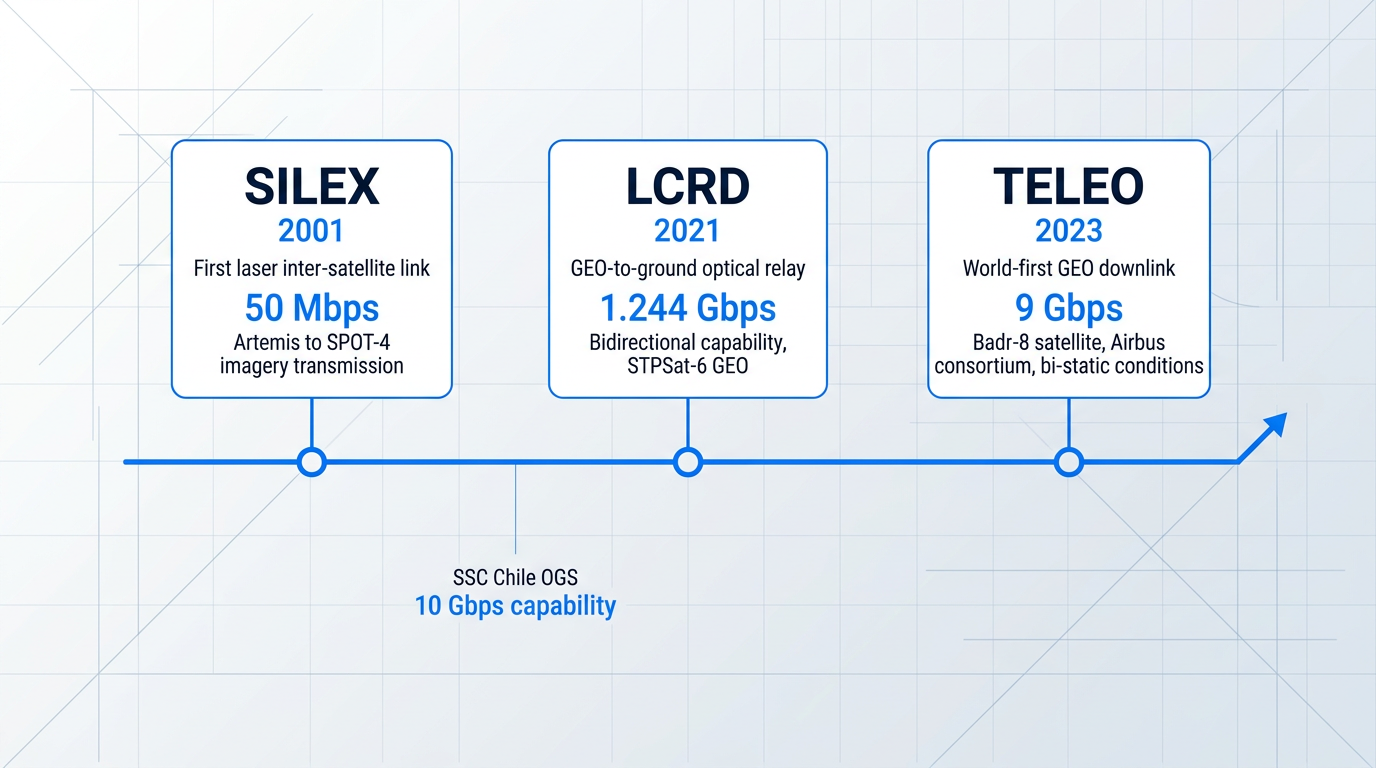
The pattern across these demonstrations is consistent: each generation raises the data rate ceiling, moves from LEO to GEO, and shifts the test conditions closer to operational reality. The gap between demonstrator and routine deployment is narrowing.
Uplink Amplification: The EDFA's Role
Early FSO demonstrations focused primarily on the downlink — satellite to ground — where the satellite's optical terminal transmits and the ground telescope receives. The uplink (ground to satellite) presents its own demanding requirements: the ground station must transmit a high-power, high-beam-quality laser signal that the satellite's optical terminal can acquire, track, and receive.
Closing the uplink power budget at the required beam quality requires amplification. The enabling technology is the EDFA — erbium-doped fibre amplifier — which provides the high output power needed while maintaining the beam quality that PAT depends on.
A key architectural decision in uplink design is whether to run the tracking beacon and the uplink data as separate amplified signals, or to nest both within a single amplified beam. The single-beam approach — where the tracking beacon rides at a lower amplitude modulation depth and the data signal above it — simplifies the optical path, reduces system complexity, and eliminates the need to co-align two separate transmit beams.
Woodrow Scientific's EDFA for free-space optical communications is built around this single-beam architecture. The tracking beacon and uplink data are nested within one amplified beam via amplitude modulation: the beacon tone rides low, and the data rides above it. Woodrow Scientific leads on this approach — it is a deliberate design choice that simplifies ground station integration rather than a feature added after the fact.
The amplifier delivers 10 W average output at 1550 nm with beam quality M² below 1.1 — the beam quality specification matters as much as the power figure, because a degraded beam profile directly undermines the pointing precision that PAT requires.
Running the tracking beacon and uplink data in one amplified beam means the ground station has one optical path to align, one amplifier to manage, and one fibre delivery to route — rather than two separate transmit chains that must be co-aligned to sub-microradian accuracy at the telescope aperture. The system complexity reduction is significant at the integration level.
Because Woodrow Scientific designs, builds, qualifies, and supports the amplifier entirely in-house — on patented technology, with engineering roots at Southampton's Optoelectronics Research Centre, the institution where the EDFA was originally developed — the hardware and software can both be configured to the specific ground station. Hardware configurability spans band selection (C-band, L-band, or dual-band from a single source), output power, emitter array configuration (2- or 4-emitter arrays with multi-station synchronisation for site and emitter diversity), and cooling. This depth of end-to-end configurability is not available from catalogue resellers or importers who lack in-house engineering capability.
Software-Definability and Standards Future-Proofing
The standards landscape for optical ground links — SDA, CCSDS, and proprietary protocols — is still actively evolving, as the ONN workshop discussions and ESA's ESTOL specification work make clear. An uplink amplifier locked to a single hardware configuration is a liability when the standard it was built for may be superseded or extended within the programme lifetime.
The same architectural principle that drove software-defined RF ground systems — reconfigurability as a hedge against standards evolution — applies directly to optical uplink amplifiers. Woodrow Scientific's Modulation-on-Demand capability addresses this: the amplifier's waveform, frequency, modulation index, and combined beacon-plus-data modulation are all software-selectable, with the ability to switch between CCSDS and SDA standards at high power across C and L-band. No hardware replacement is required as standards mature.
The amplifier is CE and UKCA certified, and is configurable as a beacon-only transmitter, an uplink amplifier, or both — giving ground station integrators flexibility in how they deploy it within the overall OGS architecture.
The Emerging Global OGS Network
The ESA ONN workshop consensus is unambiguous: Direct-to-Earth (DTE) optical links are identified as the next major growth area in satellite communications. The ONN itself — now in its third workshop cycle — is building toward a scalable, multi-user optical ground station network with common technological standards and automated operations.
Standardisation of protocols and interoperability between OGS nodes are prerequisites for this network to function. As the ONN workshop noted, DiGOS has developed an Interface Control Document specifically to standardise interfaces and enhance interoperability between OGSs and optical subsystems — a necessary step before a distributed network can operate as a coherent service rather than a collection of isolated stations.
Site diversity and network interoperability are two sides of the same requirement: you need multiple stations geographically spread to mitigate cloud cover, and you need those stations to speak the same protocol language to function as a unified service. Both conditions are engineering problems being actively solved — not aspirations waiting for technology to catch up.
The conclusion draws together the full arc of this guide — from foundational ground station architecture through TT&C, GSaaS, and software-defined systems — to frame where the ground segment is heading as optical communications move from demonstration programmes into routine operational infrastructure.
Conclusion
Ground stations: the infrastructure that makes space missions work
A satellite without a ground station is simply an object in orbit — it is the ground segment that transforms hardware in space into an operational mission, capable of receiving commands, returning data, and sustaining itself over years of service.
The field is also shifting structurally: shared service models are lowering the barrier to access, while optical communications is opening a path beyond the constraints that have defined RF links for decades.
Whether your next thread is ground station design, GSaaS evaluation, or optical uplink technology, the engineering runs deeper than it first appears — and rewards the closer look.
Frequently asked questions about satellite ground stations
Answers to common questions about how satellite ground stations work, the frequency bands used for TT&C, how spectrum licences are obtained, and how optical ground stations differ from traditional RF systems.
A teleport is a specific type of gateway ground station whose primary function is to bridge the satellite network and terrestrial infrastructure — the public switched telephone network, the public internet, or cable TV distribution headends. A standard ground station communicates with the satellite; a teleport translates that satellite link into the terrestrial network fabric. The term originated in the broadcast and cable TV era, when large hub facilities were needed to relay satellite signals into regional distribution networks. In modern usage the boundary has blurred: large gateway stations serving high-throughput internet constellations perform an equivalent function, routing traffic between the satellite layer and the terrestrial internet. The word teleport nonetheless remains in active use, particularly in broadcast and media distribution, to describe facilities whose defining role is that satellite-to-terrestrial handoff rather than spacecraft monitoring or control.
Traditional ground stations are built around hardware-specific modems, front-ends, and signal processors locked to a particular waveform, frequency plan, or communication standard. Changing missions or adopting new standards requires physical hardware replacement — a slow and costly process. Software-defined ground stations decouple the RF interface from the signal processing layer. Using SDR-based or virtualised architectures (such as Digital-IF or RF-over-IP), new waveforms, missions, and standards can be adopted by reconfiguring software rather than swapping equipment. The practical implications are significant: faster mission onboarding, lower lifecycle cost, and compatibility with evolving standards including CCSDS and proprietary waveforms. Critically, the same physical antenna and RF front-end can serve multiple missions or operators simultaneously — which is the enabling technology behind Ground Segment as a Service models, where infrastructure is shared across a customer base rather than dedicated to a single operator.
S-band (roughly 2–4 GHz) is the primary TT&C band for near-Earth missions, valued for its low atmospheric loss and reliable data rates up to approximately 1 Mbit/s. The James Webb Space Telescope, for example, uses S-band for its TT&C link. X-band and Ka-band are used where greater navigation accuracy or higher command throughput is required, including deep-space missions and certain high-data-rate applications. Optical communications are emerging as a high-throughput ground link technology but are not yet a standard TT&C medium. The ITU allocates specific sub-bands within each of these ranges for space operations, and all TT&C frequencies must be coordinated and licenced through the relevant national telecommunications administration before a mission can operate.
The two primary causes of optical link outages are cloud cover, which completely blocks a laser beam, and atmospheric turbulence, which distorts the wavefront and degrades link quality. Siting an optical ground station at high altitude places it above the bulk of the cloud layer and in thinner, more stable atmosphere, reducing both risks substantially. ESA's Optical Ground Station on Tenerife illustrates the principle well: located at 2,400 m on the Observatorio del Teide, it has operated since 1997 and sits above the typical cloud ceiling for the Canary Islands. High altitude also shortens the total atmospheric path length the laser beam must traverse, which reduces the cumulative distortion introduced by turbulence. That said, altitude alone is not sufficient for site selection — engineers also assess local seeing conditions (a measure of atmospheric stability), long-term weather statistics, and access to existing telescope infrastructure when choosing where to build.
Site diversity is the practice of distributing ground stations across geographically separated locations so that a weather-related outage at one site does not interrupt the overall link. Because rain, cloud cover, and atmospheric fade are localised events, a network of stations spread across different climate zones — or even different parts of the same region — can maintain continuous coverage by routing through whichever site is experiencing clear conditions. The concept applies in two distinct contexts. For Ka-band RF links, rain fade can attenuate the signal by tens of decibels; site diversity allows traffic to be switched to a geographically separated station that is outside the rain cell. For optical ground station networks, cloud cover causes complete link outages rather than gradual fade, making diversity even more critical — network initiatives such as ESA's Optical Nucleus Network are explicitly designed around geographic distribution as the primary cloud-mitigation strategy. Note that emitter diversity — deploying multiple synchronised laser transmitters at a single site — is a related but distinct technique that addresses turbulence effects rather than weather outages.
Satellite operators must coordinate their frequency assignments through the ITU's Radio Regulations process, which proceeds in three stages: advance publication of the planned frequency use, coordination with administrations whose existing or planned systems could be affected, and notification and recording in the ITU's Master International Frequency Register (MIFR). The coordination stage is where operators negotiate directly with one another to resolve potential interference conflicts before they arise. In parallel, the ground station itself requires a transmit-and-receive licence from the national telecommunications administration of the country in which it is physically located — this is a separate national process from the ITU coordination. For new satellite systems, the full ITU process can take several years, which is one reason optical links are increasingly attractive: because they operate outside the regulated radio spectrum, they require no ITU frequency coordination at all. Operators seeking authoritative guidance on the process should consult the ITU directly or engage a specialist spectrum regulatory adviser — the process involves legal obligations that go beyond what a technical summary can fully capture.