

Introduction
Satellite networks are carrying more data than ever, and the industry is reaching the limits of what traditional radio-frequency links can deliver at scale.
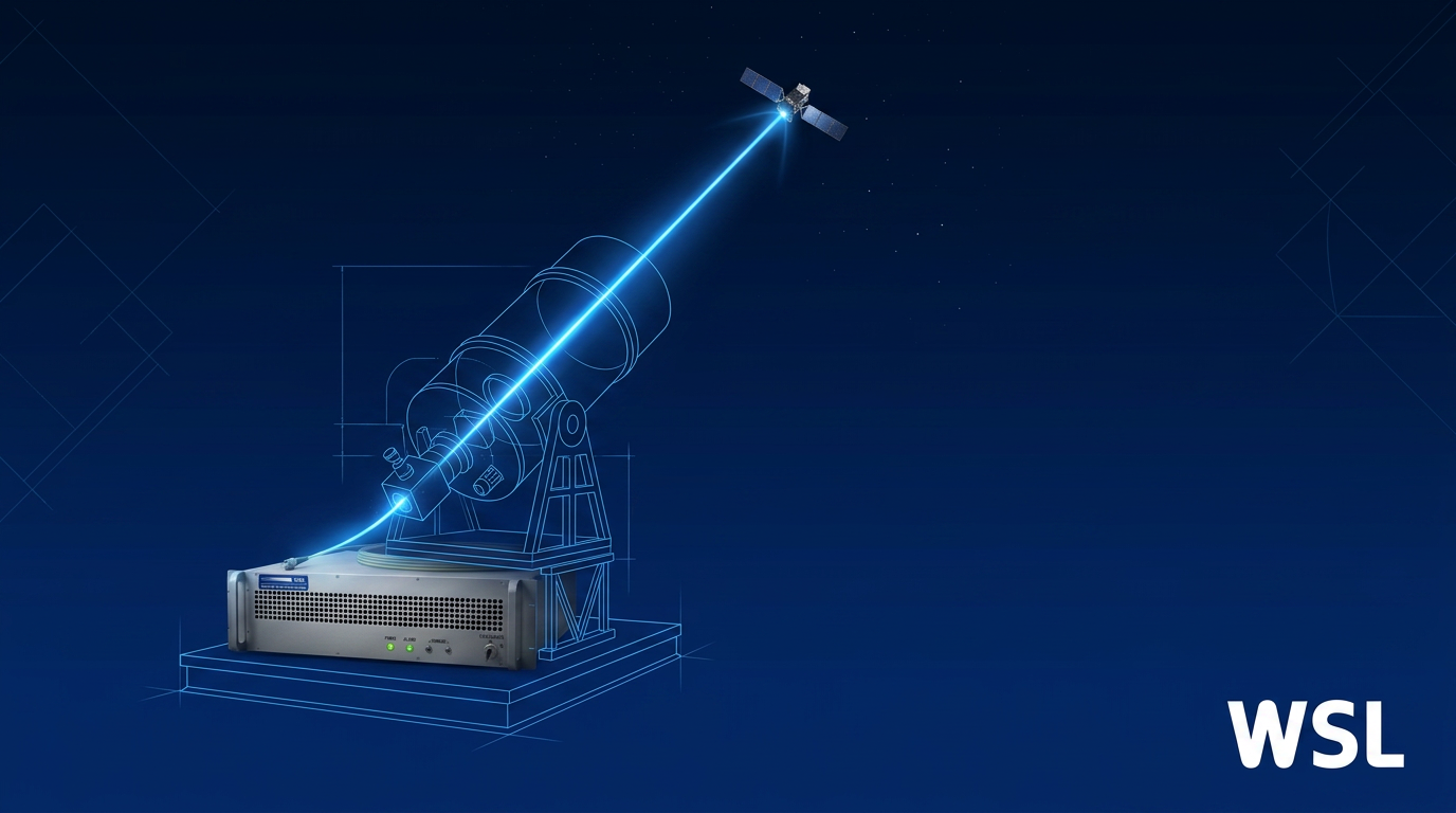
The answer taking shape across the sector is optical ground station infrastructure — ground-based systems that use laser light to support a new generation of high-throughput satellite links.
Whether you are an engineer evaluating the technology, a commercial buyer assessing integration options, or a space industry professional building broader familiarity, this guide is written with you in mind.
By the end, you will have a clear picture of how these systems work, what engineering challenges define the field, and where the technology is heading next.
TL;DR
An optical ground station is not a single device — it is a tightly integrated system where telescope, adaptive optics, pointing and tracking, laser subsystems, and software must all perform in concert.
Surging demand for satellite data capacity is accelerating standards development, driving new network architectures, and opening capabilities — including quantum-safe links — that radio-frequency systems cannot replicate.
This article covers:

What an optical ground station is and does
How OGS differs from RF ground stations
Full technology stack: telescopes, adaptive optics, PAT, lasers
Atmospheric challenges and site diversity strategies
Fixed, portable, and networked deployment forms
Emerging directions including quantum-safe links
What is an Optical Ground Station?
An RF ground station and an optical ground station both sit on Earth and talk to satellites — but the physics separating them is vast enough to demand entirely different equipment, siting logic, and engineering disciplines.
An optical ground station (OGS) is a terrestrial facility equipped with precision optical telescopes and laser systems that establishes free-space optical (FSO) communication links with satellites or spacecraft. Four elements define it: it is ground-based; it uses optical-quality mirror telescopes rather than parabolic dish antennas; its communication medium is laser light rather than radio waves; and the link traverses free space — not fibre, not waveguide.
Free-space optical communication works by encoding data onto a laser beam — typically at near-infrared wavelengths such as 1064 nm or 1550 nm — and transmitting that beam wirelessly through the atmosphere and space between a ground terminal and a space terminal. At the receiving end, a telescope collects the arriving light and a photodetector converts it back into an electrical signal, recovering the data. Unlike radio, no spectrum licence is required: optical frequencies are currently unregulated for communication use.
How OGS Differs from RF Ground Stations
The distinction between an OGS and a conventional RF ground station goes considerably deeper than swapping a parabolic dish for a telescope dome — it reshapes every aspect of the facility's design, location, and operation.
- Optical element vs. dish antenna: OGS uses precision mirror telescopes (Ritchey-Chrétien, Coudé) with stringent optical surface quality; RF stations use parabolic dish antennas collecting radio waves.
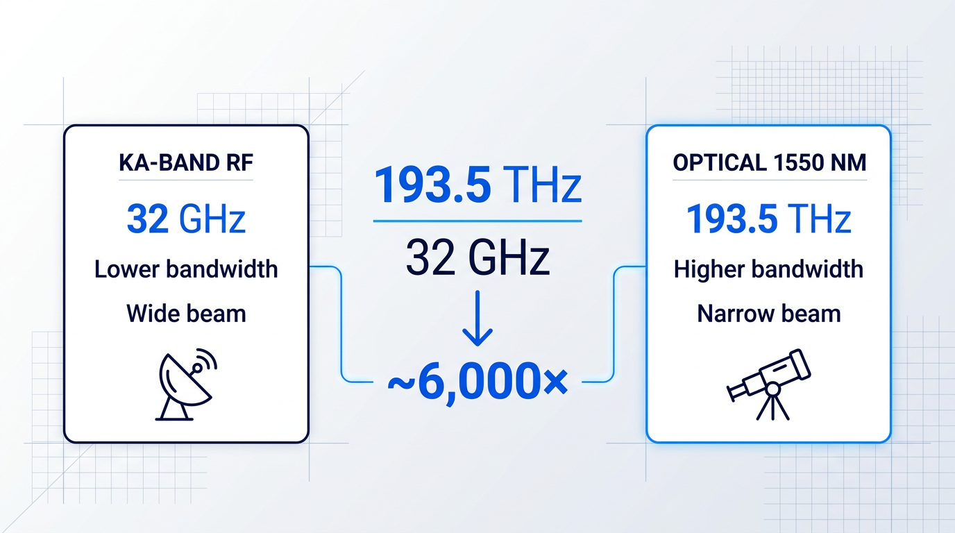
- Operating frequency and bandwidth: Optical links at 1550 nm operate at ~193.5 THz — roughly 6,000× higher than Ka-band RF at 32 GHz — enabling far higher data rates from smaller apertures.
- Siting requirements: OGS must be placed at high-altitude, low-cloud-cover sites to maximise clear-sky availability; RF stations face far more permissive siting constraints.
- Spectrum regulation: RF spectrum is licensed, congested, and bandwidth-limited. Optical links operate outside spectrum regulation entirely — a structural advantage, not a technicality.
The frequency gap is not an incremental improvement — it is the source of optical communication's fundamental capability advantage. As a NASA JPL analysis states explicitly, the 193.5 THz / 32 GHz ratio of approximately 6,000 means an optical system has the potential for a receiver signal-to-noise ratio 6,000 times higher than an equivalent Ka-band system, all else being equal.
The spectrum regulation contrast matters just as much from an industry-structure perspective. RF bands are allocated by international treaty and national licence, and the lower frequency bands are now crowded by commercial, military, and 5G telecommunications users competing for the same allocations. Optical links sidestep this constraint by design: there are currently no licensing requirements for laser communications, which means an operator can deploy additional capacity without navigating spectrum filing processes or facing the risk that a needed allocation is simply unavailable.
This is the structural driver behind the RF-to-optical shift in satellite communications. As satellite constellations multiply and per-satellite data volumes grow, the RF bottleneck becomes harder to engineer around — not because the technology is inadequate, but because the spectrum resource itself is finite and increasingly contested. FSO communications are expected to increase data rates by two orders of magnitude over traditional RF links, according to NASA's ground data systems assessments.
What an OGS Does: Core Functions
Every OGS performs three fundamental operations during a satellite communication pass, regardless of whether the link is to a low Earth orbit spacecraft or a geostationary relay.
- Transmit an uplink beacon: The OGS illuminates the satellite with a wide-beam laser beacon, enabling the space terminal to locate the ground station and correct its pointing direction before data transfer begins.
- Transmit an uplink signal beam: Once acquisition is established, the OGS sends a narrower uplink beam carrying data — commands, acknowledgements, or high-rate payload — to the satellite.
- Receive the downlink signal: The telescope collects the satellite's outgoing laser beam, and the OGS's optical receiver recovers the downlink data — typically the high-throughput payload data stream.
These three functions map directly onto the two core engineering disciplines that define OGS design: the pointing, acquisition, and tracking (PAT) system that makes the beacon and signal functions reliable, and the laser and optical receiver subsystem that carries the data.
Siting an OGS is itself a functional decision. Because optically thick clouds completely block the laser link, stations are typically placed at high-altitude locations with high clear-sky frequency and low atmospheric turbulence. ESA's Optical Ground Station at Tenerife, located at the Observatorio del Teide at 2,393 m altitude, is the canonical example: positioned well above the first inversion layer and cloud level, it offers conditions that ESA describes as optimal for Earth-to-space optical communications links.
Optical links at 1550 nm operate at ~193.5 THz — approximately 6,000 times the frequency of Ka-band RF — and require no spectrum licence. As RF bands grow more congested and licensed allocations harder to secure, optical ground links offer orders-of-magnitude higher bandwidth without regulatory constraint. This is a structural engineering reality, not a preference.
The same physics that gives optical links their bandwidth advantage also introduces three engineering challenges that have no equivalent in RF ground station design: the extreme pointing precision required because optical beams are orders of magnitude narrower than RF beams (demanding microradian-level accuracy); atmospheric turbulence effects including wavefront distortion, scintillation, and beam wander; and cloud blockage, where optically thick clouds break the link entirely. Each of these challenges defines a distinct body of OGS engineering — and each is addressed in the sections that follow, beginning with the telescope: the OGS's primary collecting and transmitting element.
Telescopes and Optical Aperture: The Collecting Foundation
Think of the telescope as the OGS equivalent of a parabolic RF dish: just as dish area determines how much radio-frequency power a ground station can collect or radiate, optical aperture area is the single hardware parameter that governs received signal power on the downlink and beam divergence on the uplink.
On the downlink, received power scales directly with aperture area — doubling the aperture diameter quadruples the collected light, improving link margin or enabling higher data rates at the same transmit power.
The aperture also provides aperture averaging: because the telescope integrates intensity across its full collecting area, short-scale intensity fluctuations caused by atmospheric scintillation are partially smoothed out, reducing signal fading on the downlink.
Aperture Requirements by Mission Type
For commercial LEO downlinks, path lengths are relatively short — typically 600 to 2,000 km at low elevation angles — and received flux is correspondingly higher, which means apertures of roughly 40 to 60 cm are generally sufficient for data reception, as confirmed by both the DLR link budget methodology and NASA's SmallSat SOA guidance.
GEO links present a fundamentally different challenge: a geostationary satellite sits at roughly 36,000 km, and the free-space loss relative to a 600 km LEO path increases by approximately 36 dB — demanding apertures in the 1 m or larger range to recover that loss without proportionally increasing transmit power.
For deep-space optical communications, the aperture requirement escalates further still: NASA calculations show that 3 m, 4 m, or even 8 m ground apertures are required depending on the distance from Earth — a regime that sits beyond most current operational OGS deployments but illustrates how aperture scales with mission distance.
| Station | Operator | Aperture | Primary Mission Focus |
|---|---|---|---|
| ESA OGS, Tenerife (Teide Observatory) | ESA / IAC | 1.0 m (Zeiss) | LEO and GEO IOT; multi-focus (Coudé and Ritchey-Chrétien) |
| OCTL, Table Mountain, California | NASA / JPL | 1.0 m (classical Cassegrain / Coudé) | LEO and deep-space; LCRD OGS-1 |
| OGSOP-NG, Oberpfaffenhofen | DLR | 0.8 m (Ritchey-Chrétien / Coudé) | LEO and GEO; AO and pre-distortion experiments |
| LCRD OGS-2, Haleakalā, Maui | NASA | 0.6 m receive / 0.15 m transmit | GEO relay (LCRD); separate Rx and Tx apertures |
| KSAT Nemea, Greece | KSAT | 0.5 m | Commercial LEO downlinks |
Comparison of real-world operational optical ground stations by aperture size, operator, and mission type, illustrating the practical aperture range across the field.
The table reveals a clear pattern: operational stations cluster between 50 cm and 1 m, with aperture choice tracking mission requirements rather than any single industry standard — smaller apertures serve commercial LEO downlinks, while GEO and experimental missions pull toward the 1 m range.
The DLR link budget paper notes that currently deployed ground segment telescope sizes from DLR, Tesat, NICT, and NASA-JPL range from 27 cm to 1.5 m, confirming that the field has not converged on a single aperture but instead reflects a spectrum of mission profiles and cost constraints.
The LCRD OGS-2 entry in the table highlights a subtler design consideration: its receive aperture (60 cm) is four times larger in diameter than its transmit aperture (15 cm), and this asymmetry is deliberate rather than incidental.
On the uplink, a larger transmit aperture narrows the beam through the diffraction limit — which is theoretically desirable — but atmospheric turbulence causes beam wander that reduces the time-averaged power delivered to the satellite, and this effect worsens as the aperture grows beyond the atmospheric coherence length.
A larger receive aperture improves downlink sensitivity through aperture averaging, but on the uplink a smaller transmit aperture can outperform a larger one by limiting beam-wander losses induced by atmospheric turbulence — which is why LCRD OGS-2 uses a 15 cm transmit aperture alongside its 60 cm receive telescope.
Cassegrain and Coudé: Engineering the Focal Plane
The Cassegrain design dominates medium and large OGS telescopes because it folds the optical path using a convex secondary mirror, achieving a long effective focal length within a compact physical tube — and crucially, it places the focal plane behind the primary mirror, where back-end instruments can be mounted in a stable, sheltered position.
The Coudé configuration extends this concept further: additional flat fold mirrors relay the beam through the telescope's rotation axes and down into a fixed, environmentally controlled instrument room that does not move with the telescope structure.
This fixed instrument room is critical for heavy or vibration-sensitive back-end equipment — adaptive optics systems, single-mode fibre couplers, and high-power laser sources — that cannot be mounted on a moving telescope without introducing mechanical stress and alignment drift.
Both the ESA OGS at Tenerife (with a Coudé focal length of 38.95 m) and NASA's OCTL at Table Mountain (whose Coudé path serves four separate optical benches in the instrument room) illustrate how the configuration enables a clean separation between the moving telescope structure and the sensitive instruments behind it.
Unlike an RF dish, which can tolerate surface irregularities of several tenths of a millimetre, an OGS telescope must be diffraction-limited at optical wavelengths: mirror surface errors must be held to a small fraction of the operating wavelength (roughly 1 µm), requiring nanometre-level polishing tolerances and low-thermal-expansion mirror substrates.
This precision requirement is what makes OGS telescopes substantially more expensive per unit aperture area than RF dishes of equivalent collecting area — the surface must be accurate enough to focus collected light onto a detector or couple it into a single-mode fibre with minimal loss.
OGS telescopes are housed within domes or protective enclosures for weather protection and thermal stabilisation: temperature gradients across the optical path create refractive index variations that degrade image quality, so enclosures are ventilated and temperature-controlled to minimise internal seeing.
Enclosures must also open quickly and reliably — a LEO satellite pass may last only a few minutes, so any delay between command and sky access directly reduces the usable link window.
The telescope collects and focuses the incoming light, delivering it to the back-end instruments — but the wavefront that arrives at those instruments has been distorted by atmospheric turbulence along the entire propagation path; correcting that distortion in real time is the role of the adaptive optics system covered in the next section.
Adaptive Optics: Correcting the Atmosphere in Real Time
The telescope collects the light — but what arrives at its focal plane is rarely the clean, coherent wavefront the satellite transmitted. The atmosphere between ground and space is a turbulent, inhomogeneous medium: thermal convection and wind shear create continuous refractive index fluctuations along the propagation path, and every one of those fluctuations bends and scrambles the laser wavefront in transit.
Beam wander shifts the entire beam laterally, as though the pointing were slightly wrong — a low-frequency, whole-beam displacement that directly degrades uplink irradiance at the satellite.
Scintillation produces rapid intensity fluctuations as wavefront components interfere constructively and destructively, causing fades and surges at the receiver that increase bit-error rates.
Higher-order phase aberrations corrugate the wavefront surface itself, blurring and spreading the focused spot — and, critically, collapsing the coupling efficiency when the beam must be fed into a single-mode fibre. The Fried parameter (r₀), the atmospheric coherence diameter, quantifies the severity: a smaller r₀ means stronger turbulence and a harder correction problem.
The Three-Component AO Closed Loop
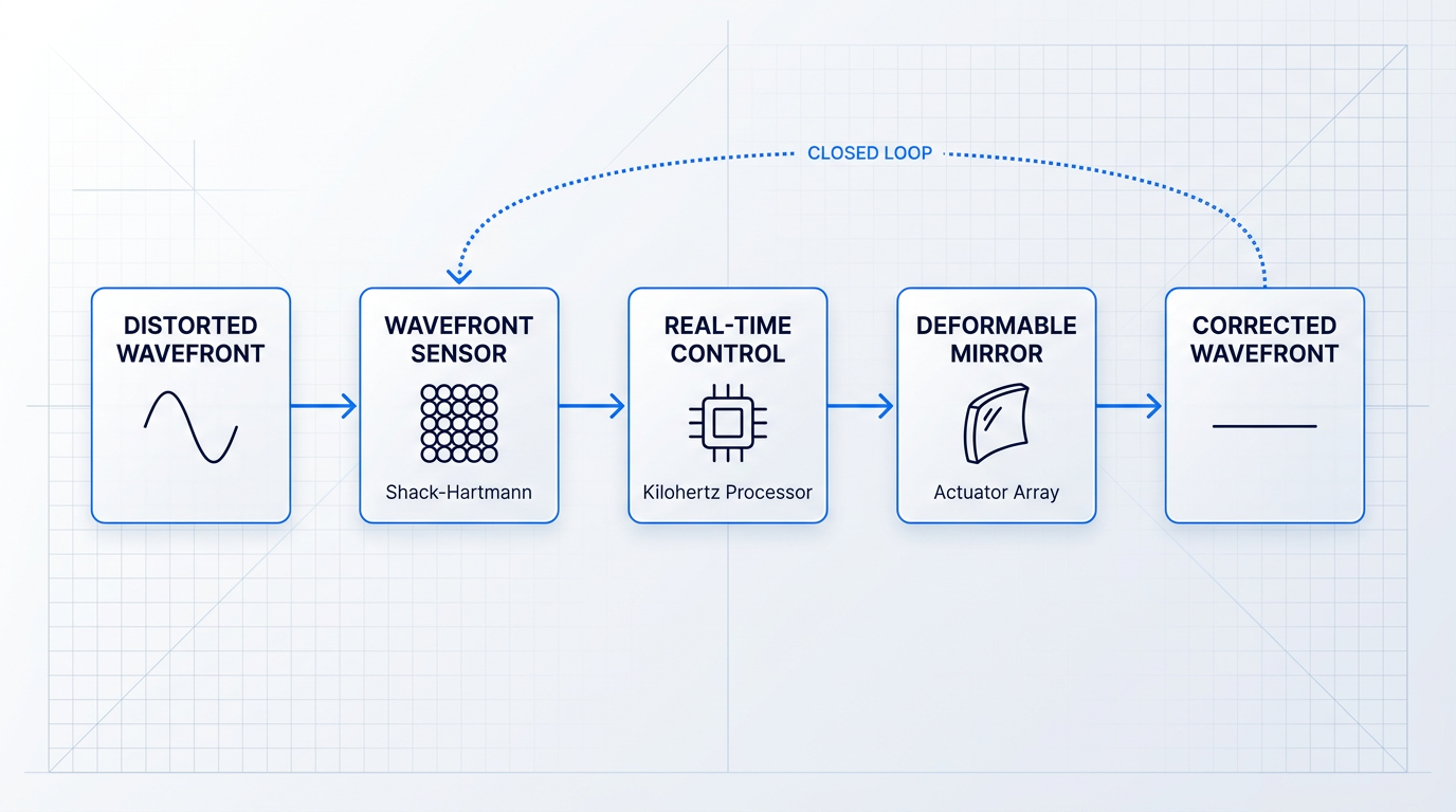
An adaptive optics system counters atmospheric distortion through a continuously running closed feedback loop built from three core components.
- Wavefront Sensor (WFS): Typically a Shack-Hartmann sensor: a microlens array divides the beam into sub-apertures and measures local wavefront slope across each, mapping the full distortion pattern.
- Deformable Mirror (DM): A mirror with an array of actuators that reshapes its surface in real time, applying the conjugate of the measured distortion to cancel it — analogous to noise-cancelling headphones inverting an unwanted signal.
- Real-Time Control Computer: Computes actuator commands from WFS measurements using a least-squares or modal reconstructor algorithm, running at kilohertz rates to keep pace with the atmosphere's evolution timescale.
The loop is closed: the corrected wavefront feeds back into the sensor, and the system iterates continuously toward a flat, diffraction-limited output. JPL's Integrated Optical System design requires frame rates on the order of 10 kHz to maintain performance at low elevation angles and challenging seeing conditions.
Downlink AO: Coupling Light into Single-Mode Fibre
On the downlink, the OGS receives a wavefront distorted by the full atmospheric column between satellite and ground. The AO system corrects these phase aberrations so the received beam can be efficiently coupled into a single-mode fibre (SMF), which carries the signal to the optical modem.
The coupling step is the critical functional bottleneck. DLR research shows that in the absence of correction, coupling efficiency (η) falls below −20 dB at low elevation angles; correcting 30 wavefront modes reduces that figure to around −4 dB even under strong turbulence conditions.
This requirement is especially stringent for coherent modulation schemes, which depend on a clean single-spatial-mode input — a connection covered in detail in the laser subsystems section.
Uplink Pre-Distortion AO: Shaping the Beam Before Launch
On the uplink, the OGS must transmit a beam that will survive the atmospheric gauntlet and arrive at the satellite with acceptable quality. Pre-distortion AO addresses this by measuring the current atmospheric distortion from the downlink wavefront and pre-shaping the outgoing beam with the conjugate distortion, so the atmosphere partially unwinds the pre-applied correction during propagation.
The performance gains from even partial correction are substantial. DLR experimental results show that tip/tilt correction alone — compensating beam wander — delivers approximately 4.5 dB improvement in the link budget, with a further ~1.5 dB from extending correction to 16 higher-order AO modes.
Simulation studies of bidirectional free-space optical links for GEO feeder link scenarios show that pre-distortion AO can reduce total uplink losses by up to 10 dB and reduce scintillation at the satellite receiver by an order of magnitude.
At 99.9% link uptime requirements, pre-distortion AO can ease link budget requirements by 20–40 dB — a margin large enough to make AO a practical prerequisite for near-continuous operation rather than an optional enhancement.
DLR simulation results show that adding laser guide star correction on top of standard pre-distortion AO yields an additional uplink loss reduction of up to 8 dB in idealised conditions — a gain that is otherwise unachievable through downlink-referenced correction alone.
The Point-Ahead Angle: AO's Fundamental Limitation
Pre-distortion AO relies on a critical assumption: that the downlink and uplink travel through the same column of atmosphere, so the downlink wavefront measurement is a valid proxy for uplink distortion. For a moving satellite, this assumption breaks down.
Because the satellite is moving at orbital velocity, the uplink beam must be aimed slightly ahead of the satellite's current apparent position — an angular offset called the point-ahead angle (PAA). For LEO satellites at ~600 km altitude, the PAA is approximately 50 µrad; for GEO, it is around 17–20 µrad.
If the PAA exceeds the isoplanatic angle — the angular radius over which the atmosphere can be treated as uniform — the downlink wavefront measurement no longer accurately represents the distortion the uplink beam will encounter, and pre-compensation degrades accordingly.
DLR research confirms that AO pre-correction performance is greatest at low point-ahead angles and degrades as the PAA grows relative to the isoplanatic angle. This geometric constraint is the fundamental ceiling on downlink-referenced AO, and it directly motivates the laser guide star approach. The full pointing geometry of the PAA is addressed in the section on pointing, acquisition, and tracking.
Laser Guide Star AO: Measuring the Uplink Path Directly
To overcome the isoplanatic angle constraint, researchers are developing laser guide star (LGS) AO systems that create an artificial wavefront reference source in the atmosphere — in the direction the uplink will actually travel, rather than the direction the downlink arrived from.
A sodium LGS excites fluorescence in the mesospheric sodium layer at approximately 90 km altitude; Rayleigh-backscatter LGS systems use lower altitudes. Either approach samples the uplink atmospheric path directly, allowing the AO system to measure and pre-compensate uplink distortion without the PAA penalty that limits downlink-referenced correction.
ESA's ALASCA project, based at the ESA Optical Ground Station in Tenerife, is developing a TRL6 operational optical feeder link test facility implementing sodium LGS-AO for full uplink pre-compensation, targeting 24/7 operability with the Alphasat geostationary satellite. LGS AO for satellite communications remains an active development area, not a deployed operational capability.
AO corrects the wavefront once a link is established — but establishing and holding that link across a fast-moving satellite pass is its own engineering challenge. That is the domain of the pointing, acquisition, and tracking system, covered in the next section.
Pointing, Acquisition, and Tracking: Closing the Link
Consider the geometry: a laser beam roughly the width of a dinner plate, transmitted from the ground, must strike a satellite 500 km overhead travelling at several kilometres per second — and must do so to an angular precision measured in microradians, a unit so small that a single microradian corresponds to about one millimetre of offset at one kilometre range.
This is the foundational challenge of Pointing, Acquisition, and Tracking (PAT): the mechanism that establishes the optical link before any data can flow, and keeps it alive for the duration of the pass.
An RF ground station can tolerate pointing errors of several degrees — its beam is broad enough that a satellite easily falls within it once the antenna is aimed in the right general direction. An optical beam's divergence is orders of magnitude narrower, and the acceptable pointing error for a tight optical link is a small fraction of a microradian. There is simply no RF equivalent to the engineering challenge this creates.
The previous section covered how adaptive optics corrects the wavefront once a link is established. PAT is what creates that link in the first place — without it, there is nothing for AO to work on.
The PAT process unfolds in three distinct, sequential phases, each with its own hardware demands and design trade-offs.
- Acquisition: The OGS transmits a wide, divergent beacon beam sized to cover the satellite's pointing uncertainty zone. The satellite's tracking sensor detects the beacon and the spacecraft slews its terminal toward the ground station, while the OGS simultaneously searches the sky volume where the satellite is predicted to be from orbital mechanics.
- Closed-Loop Tracking: Once both terminals have detected each other, they transition from open-loop (predict-and-point) to closed-loop (measure-and-correct) operation, using beacon or signal feedback to maintain mutual line of sight.
- Data Transmission: With the link locked, data flows — but this is not a static state. The satellite is moving, the atmosphere is perturbing the beam, and the fine-pointing control loops run continuously throughout the pass to hold the link.
The acquisition phase is where the most critical design trade-offs live. A wider beacon divergence covers the satellite's pointing uncertainty more reliably and speeds up acquisition — but it also spreads the transmitted power over a larger solid angle, reducing the irradiance at the satellite's detector. DLR's operational OGS systems have used beacon divergences on the order of 0.5 mrad to guarantee the beacon illuminates the satellite given the combined pointing uncertainty of the OGS and the orbital prediction.
The key variables governing acquisition are beacon divergence, transmitted power, and the modulation frequency of the beacon signal — a modulated beacon allows the satellite's tracking sensor to distinguish it from background light using digital filtering. Once the satellite acquires the beacon, it corrects its attitude and begins illuminating the ground station with its communications beam, completing the mutual acquisition handshake.
The Tracking Hardware: FSMs and Four-Quadrant Detectors
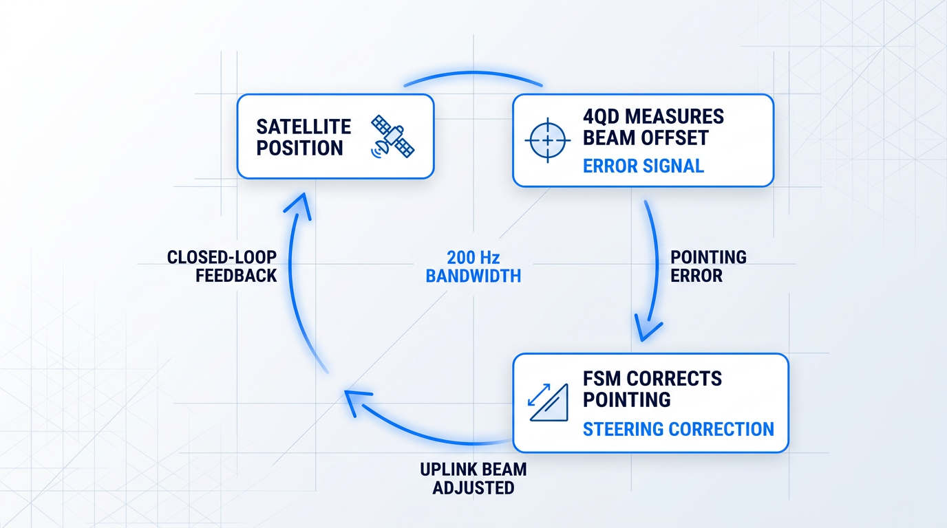
Closed-loop tracking is implemented by two hardware components working in concert as a fast feedback system.
- Fine Steering Mirror (FSM): A fast-actuated mirror within the optical path that applies high-bandwidth pointing corrections in response to the tracking error signal, operating far beyond the bandwidth of the telescope mount.
- Four-Quadrant Detector (4QD): A position-sensitive photodetector that measures the centroid of the incoming beacon beam and generates an error signal proportional to the angular offset from the desired pointing direction.
The two components operate as a closed feedback loop: the 4QD senses the pointing error, and the FSM corrects it — continuously, at the bandwidth required to keep the fast-moving satellite within the beam. DLR's OSIRIS4CubeSat programme demonstrated a control loop bandwidth of 200 Hz for the fine pointing assembly, sufficient to compensate residual spacecraft attitude errors and maintain the link at near-diffraction-limited divergence.
There is a further geometric complication that is easy to overlook but significant in practice: the point-ahead angle (PAA).
Because a LEO satellite is travelling at orbital velocity, the light travel time between ground and satellite means the satellite will have moved by the time the uplink beam arrives. The uplink beam therefore cannot be aimed at the satellite's current position — it must be aimed at where the satellite will be when the photons arrive. This is the point-ahead angle: the angular offset between the received downlink direction and the required uplink transmit direction.
The intuition is the same as a hunter leading a moving target: you aim where the bird will be, not where it is. For LEO satellites, published measurements place the PAA typically between approximately 20 µrad near the horizon and up to approximately 50 µrad at zenith — a range that is directly comparable to the beam divergence of a high-rate optical link and therefore cannot be ignored or approximated.
For LEO optical links, the point-ahead angle — the offset between uplink transmit direction and received downlink direction — ranges from roughly 20 µrad near the horizon to around 50 µrad at zenith. This is comparable to the beam divergence itself, meaning the PAA must be calculated and applied dynamically throughout every pass, not estimated once at link setup.
The PAA also has a direct consequence for adaptive optics, as noted in the preceding section: because the uplink and downlink travel different atmospheric paths (separated by the point-ahead angle), downlink wavefront measurements cannot fully pre-correct the uplink. The PAA is therefore both a tracking problem and an AO problem — the two subsystems are coupled through this geometry.
The operational urgency of fast acquisition becomes clear when you consider the contact window available. A LEO satellite typically offers only a few minutes of contact per pass — commonly in the range of 3 to 8 minutes depending on orbit altitude and the elevation angle above the horizon.
Every second spent in acquisition is a second not spent transferring data. NASA's TBIRD mission, which demonstrated 200 Gbps downlink rates from a 6U CubeSat, achieved pull-in times of 10 to 30 seconds on orbit — a result that reflects both careful system design and the hard operational reality that sub-minute acquisition is a requirement, not an aspiration. At 200 Gbps, even 30 seconds of acquisition overhead represents a significant fraction of the available pass budget.
This constraint directly shapes beacon architecture decisions. Wider beacon divergence accelerates acquisition by covering the uncertainty zone faster, but at the cost of power density at the satellite. Narrower divergence concentrates power but demands higher pointing accuracy before the beacon is switched on. The acquisition search strategy — whether the satellite performs a spiral scan, a grid search, or relies on open-loop pointing — is an equally important design variable.
One architectural approach worth understanding is the single-beam beacon-and-data architecture. The conventional design uses separate transmitters for the tracking beacon and the uplink data signal — two optical paths, two amplifiers, and two sets of alignment hardware. An alternative combines both functions in a single amplified beam: a low-frequency modulation tone (in the range of 7 to 10 kHz, based on demonstrated missions including O2O and TBIRD-related designs) serves as the tracking beacon that the satellite's detector can lock onto, while data modulation occupies the higher-frequency regime of the same beam.
This approach eliminates the dedicated beacon transmitter, reduces system complexity, and simplifies optical alignment — because the tracking reference and the data signal are co-propagating in the same beam, there is no risk of differential pointing between them. It is an active area of OGS design rather than a universal standard, and different missions have made different architectural choices based on their specific link budgets and spacecraft terminal designs.
With the PAT subsystem establishing and maintaining the link, the next design layer is the laser and signal generation chain that determines what actually travels over it — wavelength selection, amplifier architecture, modulation formats, and the communication standards that govern interoperability.
Laser Subsystems, Modulation, and Communication Standards
Once the telescope is pointed and the link is tracked, the next question is what signal actually travels through it — and the answer involves a carefully chosen wavelength, a specific amplifier architecture, and an evolving set of standards that every optical ground station integrator must navigate.
The industry has converged on 1550 nm as the dominant wavelength for OGS uplinks and downlinks, driven by four compounding advantages: a higher maximum permissible exposure threshold compared with 1064 nm (though Class 4 laser safety procedures and eyewear remain mandatory), direct compatibility with erbium-doped fibre amplifier (EDFA) technology, lower atmospheric attenuation in this spectral window, and the wide availability of mature InGaAs detector arrays.
That said, 1064 nm is not obsolete — it remains in active use across legacy terminals and some deep-space missions, so the 1550 nm picture is a strong consensus, not a closed monoculture.
Most high-power OGS uplink transmitters are built around a Master Oscillator Power Amplifier (MOPA) architecture: a low-power seed laser is first modulated to encode the signal, then that modulated output is amplified by an EDFA to the power levels the link budget requires.
The engineering value of MOPA is the clean separation of modulation from high-power output — the seed laser can be optimised for spectral purity and modulation agility without needing to handle high power itself, enabling flexible, high-fidelity signal generation across a range of waveforms.
Operating in the C-band (1530–1570 nm) or L-band, the EDFA provides the amplification needed to close the uplink budget: NASA's LCRD ground stations, for example, each use 20 W uplink transmitters, while ESA's UPLINK project targets 20 W average power (up to 40 W peak) for next-generation OGS integration.
At these power levels, high-power EDFA designs must manage Stimulated Brillouin Scattering (SBS) — a nonlinear effect that can degrade beam quality as output power rises, addressed through careful linewidth engineering and power management in the amplifier architecture.
Modulation Formats for Free-Space Optical Links
- OOK (On-Off Keying): The simplest format, compatible with direct detection. Widely used across LEO and GEO links where receiver complexity must be minimised.
- PPM (Pulse-Position Modulation): Preferred for photon-starved deep-space links; maximises photon efficiency at the cost of spectral efficiency. CCSDS specifies SCPPM on the downlink.
- DPSK / Coherent Formats (BPSK): Enable higher spectral efficiency for high-rate GEO links. NASA's LCRD operates at 1,244 Mbps using DPSK, but require more complex receiver processing.
The right modulation format is not fixed at procurement — it depends on the link geometry, the satellite terminal's receiver, and the standards framework the programme operates under, which is where the standards discussion becomes central.
Communication Standards: CCSDS and SDA
The Consultative Committee for Space Data Systems (CCSDS) provides the baseline for cross-agency civilian interoperability: CCSDS 141.0-B-1 (August 2019) specifies the optical communications physical layer, including C-band centre frequencies defined as 193.1 + n×0.1 THz, transmitter linewidth, slot widths from 0.125 to 512 ns, and pulse timing jitter requirements; CCSDS 142.0-B-1 (August 2019) covers the coding and synchronisation sublayer, including SCPPM channel coding.
A distinct framework governs US Department of Defense programmes: the SDA Optical Communications Terminal (OCT) Standard v4.0.0 (June 2024), published by the Space Development Agency, defines interoperability specifications for optical terminals across space-to-space, space-to-ground, space-to-air, and space-to-maritime links within the Proliferated Warfighter Space Architecture (PWSA) — a scope and community entirely separate from CCSDS.
Both frameworks are living documents under active revision: the SDA issued an intermediate v3.2.0 alongside v4.0.0 to manage Tranche 3 transition risk, and v4.0.0 itself introduced a new long-range waveform with further updates anticipated — meaning a subsystem hard-wired to any single version of either standard carries real compliance risk as requirements evolve.
The SDA OCT Standard has moved from v3.1.0 through v3.2.0 to v4.0.0 within a single procurement cycle — an uplink amplifier that cannot be reconfigured in software is already behind the standards curve before it is installed.
The practical engineering response is a software-definable uplink amplifier — one that can be reconfigured across modulation format, beacon parameters, and standards compliance without hardware replacement.
Woodrow Scientific Limited's EDFA for free-space optical communications illustrates this approach in a distinctive way: its single-beam architecture nests the tracking beacon at a lower modulation frequency with the uplink data above it in one amplified beam, eliminating the need for a separate beacon path.
Beyond the single-beam design, the amplifier's Modulation-on-Demand capability makes it switchable across CCSDS, SDA, and proprietary standards at high power across C/L-band — with software-selectable waveform, frequency, and modulation index — while the hardware itself is configured per ground station across band, output power, emitter count, cooling, and form factor.
The amplifier carries CE and UKCA certification and is built to a 10 W average output (higher on request) with M² < 1.1 beam quality, with SBS managed at full power.
WSL (founded 2012) designs, builds, qualifies, and supports the amplifier entirely in-house on patented technology, with fibre-amplifier expertise rooted in Southampton's Optoelectronics Research Centre — the birthplace of the EDFA itself.
Many suppliers in this market are resellers or importers rather than manufacturers, which means limited engineering support, slower access to spares, and no real ability to adapt the product as programme requirements or standards evolve — a meaningful distinction when procurement decisions span multi-year programmes.
The laser subsystem and its modulation format define the signal that travels to the satellite; what orchestrates those subsystems in real time — scheduling passes, managing the link state, and driving modulation control during a live contact — is the software and control layer, which the next section covers.
EDFA Technology Built for Free-Space Optical Links
The 1550 nm laser subsystem is only as capable as the amplifier behind it. Woodrow Scientific's EDFAs are engineered specifically for FSOC — delivering high average output power with on-demand modulation.

Software, Control Systems, and Link Management
Every hardware subsystem covered in this guide — the telescope mount, adaptive optics system, fine steering mirror, detectors, and laser sources — depends on software to function as a coherent whole. The station control software is not a thin wrapper around these components; it is a real-time orchestration layer that sequences, coordinates, and monitors all of them simultaneously, often to timing tolerances measured in milliseconds.
During a satellite pass, the control system must open the dome, slew the mount to the predicted acquisition position, trigger beacon search, transition from open-loop to closed-loop tracking, configure the laser and detector subsystems, manage the communication link, and execute a clean teardown — all without a human operator issuing each command in sequence.
Pass Automation and Robotic Operation
The operational case for full automation is straightforward: a LEO satellite pass typically lasts only a few minutes, and a networked optical ground station may need to execute dozens of passes per day across multiple satellites. Human-in-the-loop operation at that tempo is neither scalable nor reliable.
DLR's FOGATA station in Almería, Spain, demonstrates what fully robotic operation looks like in practice. Its monitoring and control (M&C) system — developed in-house — automates satellite passes without requiring human interaction, while still offering the option for manual intervention when needed. Customers can book passes remotely via a web service, and the passes are then scheduled automatically with the dedicated ground stations using a CCSDS-standardised approach, ensuring compatibility across different agencies and mission operators.
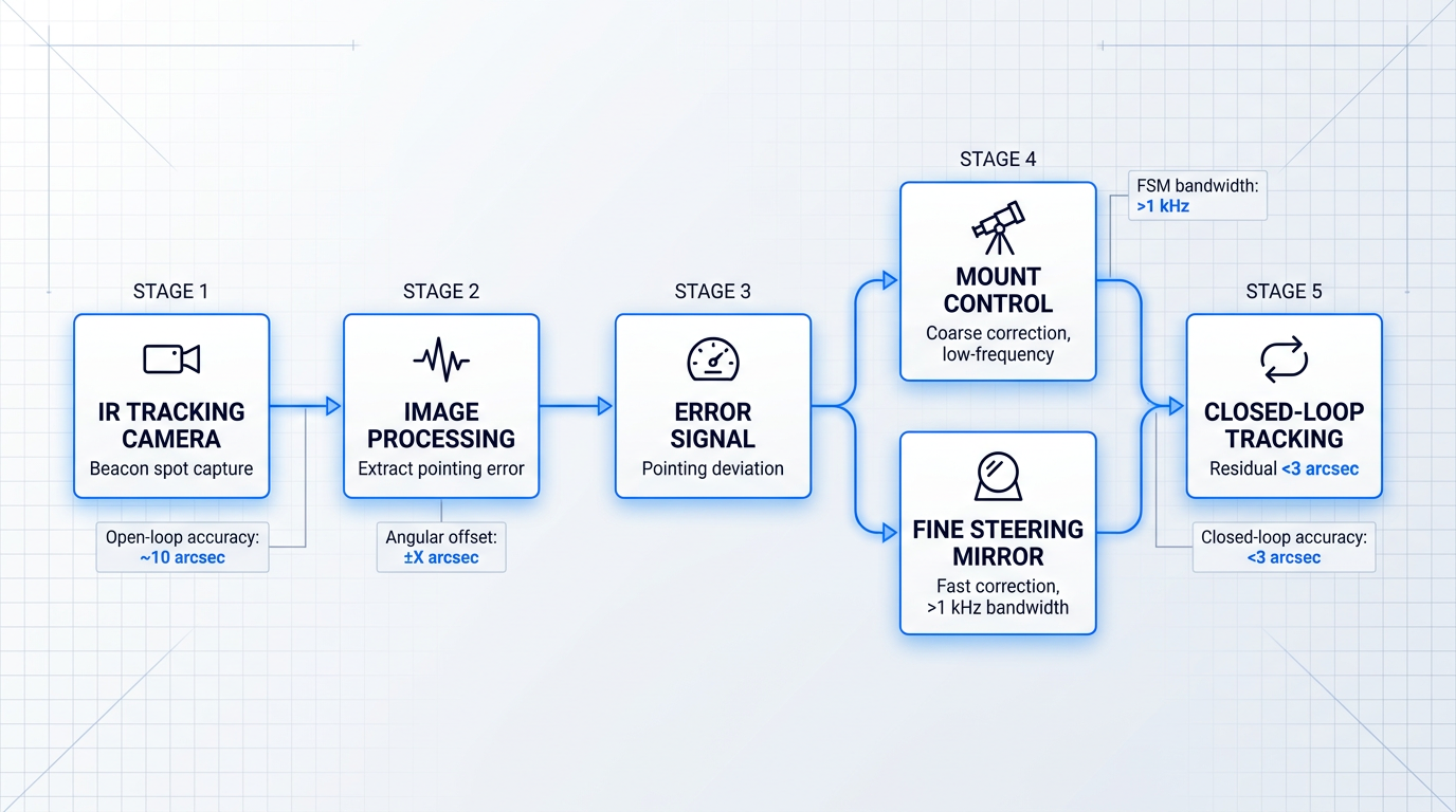
The FOGATA M&C system encompasses the full automation chain: device drivers for the station's hardware, closed-loop tracking via an infrared camera and image processing, and the scheduling and pass execution logic that ties them together.
Closed-Loop Tracking in Software
The tracking loop is where real-time software performance is most critical. A near-infrared tracking camera — typically a narrow field-of-view sensor — captures the satellite's beacon or signal spot and feeds frames into image processing algorithms that extract the pointing error: the angular offset between the satellite's current position in the focal plane and the target position.
That error signal is passed to the tracking manager, the software component responsible for commanding both the telescope mount and the fine steering mirror (FSM). The mount corrects for coarse, low-frequency pointing drift; the FSM handles the fast, high-frequency residuals at bandwidths exceeding 1 kHz. DLR's TOGS system illustrates the layered approach: a PAT computer handles coarse tracking via CAN bus commands to the mount engines, while a Visual Tracker running on a separate processor closes the fine loop through the narrow field-of-view camera.
Open-loop tracking — using orbital two-line elements or consolidated prediction format data — typically achieves pointing accuracy around 10 arcseconds. Closing the loop with the fine-tracking system brings that residual below 3 arcseconds, which is the regime where reliable link acquisition and data transfer become possible.
Link Management Systems
Station-level automation handles the mechanics of a single pass. At network scale, a Link Management System (LMS) is needed to coordinate scheduling, commanding, and timeline management across multiple stations and missions simultaneously.
DLR's LMS for the European Data Relay System (EDRS) is a well-documented example of this architecture in operational use. Developed at the German Space Operations Center (GSOC) using its Plato scheduling library, the LMS serves as the mission planning component for the two DLR-hosted EDRS control centres. It participates in the automated scheduling and commanding process, and is notably the first mission planning system at GSOC to perform event-based scheduling with real-time timeline updates — meaning the schedule is not fixed at the start of a pass but can adapt dynamically as events unfold.
The LMS coordinates with mission operations centres, manages the sequencing of link requests, and handles the commanding of the EDRS-A and EDRS-C payloads. As OGS networks grow in station count and link volume, this kind of automated, event-driven planning infrastructure becomes as operationally critical as any hardware subsystem.
As optical ground station networks scale from single sites to multi-station constellations, the link management system transitions from a scheduling convenience into a mission-critical engineering component — one whose reliability and adaptability directly determines network availability.
Hardware Abstraction Layer
One of the most consequential software engineering challenges in OGS development is hardware heterogeneity: telescopes, cameras, domes, lasers, detectors, and environmental sensors from different manufacturers all require different low-level control logic, yet the higher-level station software must treat them as a coherent system.
The solution is a hardware abstraction layer (HAL) — a software architecture that decouples device-specific driver logic from the higher-level station control and scheduling systems. ESA's ongoing OGS software project (Activity 6B.126, kicked off in May 2025) is developing precisely this: an abstraction layer designed to facilitate integration and control of heterogeneous optical hardware components through standardised software interfaces.
The ESA project targets compatibility with three established interface standards: ASCOM (Astronomy Common Object Model, widely used for telescope and instrument control), INDI (Instrument-Neutral Distributed Interface, a cross-platform protocol for astronomical hardware), and GSSC (ESA's own Ground Segment Software Components framework). By designing to these standards, the abstraction layer allows different hardware devices to be swapped or upgraded without requiring changes to the higher-level control software — a genuine engineering value as OGS technology evolves.
The ESA project is structured around two main deliverables: an OGS Hardware Adapter (the abstraction and orchestration layer that accepts operational tasks via local or remote interface) and an OGS Software Client (the user-facing interface for scheduling communication tasks and monitoring station status). Together, they represent an institutional effort to build scalable, future-proof infrastructure for optical communication and space surveillance.
Signal Processing Pipeline
On the receive side, the software processing chain begins the moment the optical signal is converted to electrical by the photodetector front-end. For a coherent receiver, the digital signal processing (DSP) pipeline handles timing recovery, carrier synchronisation, adaptive equalisation, and finally forward error correction (FEC) decoding — each stage compensating for a specific class of impairment.
Three challenges define the difficulty of this pipeline in the satellite optical context. Atmospheric fading causes rapid intensity fluctuations that the FEC and equalisation stages must absorb. Doppler shift — arising from the satellite's radial velocity, which varies by several kilometres per second across a LEO pass — induces a carrier frequency offset that the carrier recovery stage must track and compensate continuously; left uncompensated, it degrades demodulation performance severely. Timing jitter requires robust timing recovery to maintain symbol synchronisation throughout the pass.
Monitoring, Diagnostics, and Link Quality
A complete OGS software stack includes a monitoring layer that runs continuously alongside the control and processing functions. Environmental sensors, atmospheric turbulence monitors — including DIMM seeing monitors (differential image motion monitors, which measure the Fried parameter) and scintillometers — feed data into the station's situational awareness picture throughout each pass.
The key link quality metrics logged are the scintillation index (quantifying intensity fluctuation statistics), bit error rate (BER), and received optical power. DLR's OGS at Oberpfaffenhofen has operated a suite of these instruments — including a pupil camera, Shack-Hartmann wavefront sensor, and power meters — to build measurement datasets that characterise atmospheric turbulence as a function of elevation angle.
DLR has also developed an all-sky camera system for monitoring optical satellite downlinks, based on an InGaAs infrared camera operating at 1550 nm with a 140-degree field of view. Without requiring any mechanical tracking, the system can locate a satellite, estimate its azimuth and elevation, and assess the received intensity against the expected link budget — providing a validation tool that can detect the satellite signal even on passes where the main OGS tracking system does not acquire it.
This monitoring data serves two distinct purposes: real-time link decisions — whether atmospheric conditions warrant attempting a pass, or whether a degraded link should be handed off or aborted — and post-pass analysis, building the long-term statistical dataset that informs site selection, network planning, and system refinement.
The monitoring and link management infrastructure described in this section is also the mechanism by which an OGS responds to the most operationally challenging variable in free-space optical communication: the atmosphere itself. What happens when atmospheric conditions deteriorate beyond what the software can compensate for in real time is the subject of the next section.
Atmospheric Challenges: Cloud Cover, Turbulence, and Diversity
Even with a fully optimised telescope, adaptive optics system, and precision tracking loop, the atmosphere imposes constraints that no amount of ground-side engineering alone can fully overcome. The hardware can be perfect; the sky may still not cooperate.
Two distinct impairment classes govern optical ground station availability, and they must be understood separately — because they differ in mechanism, timescale, severity, and the mitigation strategies they demand. Conflating them leads to the wrong engineering responses.
Atmospheric Turbulence and Scintillation
Atmospheric turbulence is always present to some degree. Refractive index fluctuations — driven by thermal convection and wind shear in the lower atmosphere — cause continuous, rapid intensity variations in the propagating beam, a phenomenon known as scintillation.
On the downlink, scintillation produces intensity fluctuations at the ground receiver on timescales of milliseconds. Research from NASA NTRS and DLR indicates that under strong turbulence conditions, fading events exceeding 10 dB can occur, with individual fades lasting long enough to corrupt entire data packets and degrade bit error rate significantly.
Beam wander and wavefront distortion are also part of the turbulence picture, each introducing additional loss mechanisms beyond pure intensity scintillation.
For the downlink, aperture averaging provides a practical partial mitigation: when the receive aperture is larger than the intensity correlation width of the scintillation pattern, the telescope spatially averages the fluctuations across its collecting area, reducing the variance of received power. DLR measurements confirm this effect clearly — a 40 cm aperture achieves an aperture averaging factor of approximately 0.1–0.2 depending on elevation, meaningfully reducing scintillation compared to a point receiver.
For the uplink, aperture averaging does not apply in the same way: the intensity correlation scale at the satellite is of the order of hundreds of metres, far larger than any practical ground aperture. The established uplink mitigation is AO pre-distortion of the transmitted beam, as covered in the adaptive optics section of this guide.
Cloud Blockage: The Total Impairment
Cloud blockage is categorically different from turbulence. It is not a signal quality degradation — it is a complete link severance. Optically thick clouds attenuate optical signals by hundreds of decibels per kilometre; DLR research quantifies water cloud attenuation at 100–600 dB/km. No adaptive optics system, no aperture size, and no link margin can bridge that loss.
Thin clouds attenuate rather than block entirely, but even moderate cloud cover can push link margins beyond what the system can tolerate. When an optically thick cloud sits between the OGS and the satellite, the link is simply unavailable — the only responses are avoidance and redundancy.
Site selection at high-altitude, low-cloud-probability locations reduces the frequency of blockage events. But it cannot eliminate them. The only engineering solution that can guarantee high availability against cloud blockage is having another ground station available when one site is obscured.
Research consistently estimates that a single optical ground station at a typical European location achieves roughly 60–70% clear-sky availability annually, leaving 30–40% of satellite passes inaccessible from that site alone. Empirical data from the NASA LCRD experiment tells a similar story for well-sited locations elsewhere: OGS-1 at Table Mountain, California recorded 57.8% availability over the experiment period.
This figure is the quantitative case for network diversity. A single site, however well-sited, cannot meet the greater-than-99% availability that commercial communication services typically require.
Site Diversity: The Network-Level Response
Site diversity means deploying multiple optical ground stations at geographically separated locations whose cloud cover statistics are statistically independent — ideally anticorrelated. The key design parameter is the meteorological correlation length: cloud cover structures are spatially correlated over distances of roughly 300 km or more, so stations must be separated by at least this distance to experience genuinely independent weather.
ESA guidance specifies separations of at least 300–500 km for statistically uncorrelated cloud cover, a figure consistent across multiple DLR and ESA studies on optical feeder link site diversity.
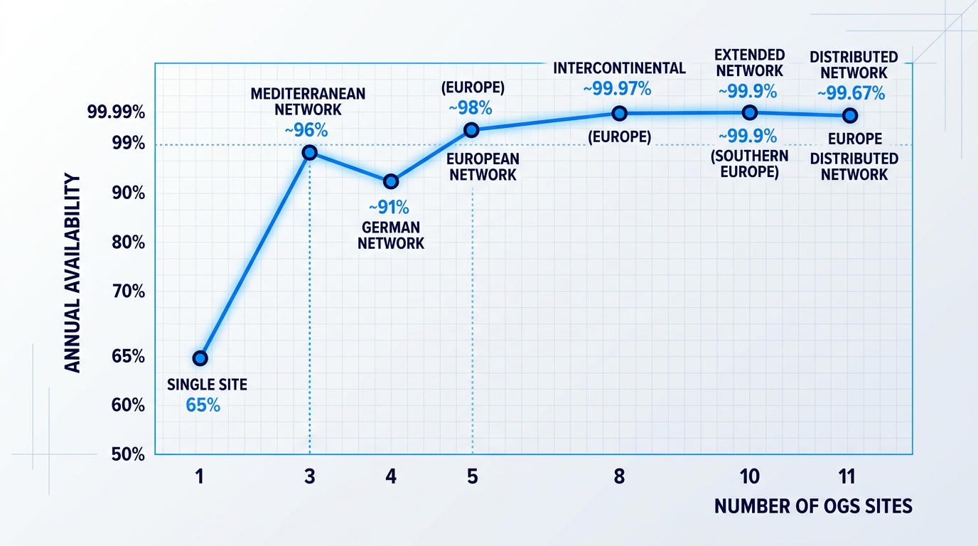
The availability gains from multi-site networks are well-documented in the research literature. The figures below, drawn from DLR and NASA studies, illustrate how network size translates into availability for GEO optical feeder link scenarios.
| Network Configuration | Approx. Annual Availability | Source |
|---|---|---|
| 1 site, typical European location | ~60–70% | DLR / NASA NTRS (multiple studies) |
| 4 sites, inside Germany (spaced as far apart as possible) | ~91% summer half-year; ~73% winter half-year | DLR (Giggenbach et al.) |
| 3 sites, Mediterranean (Skinakas, Marseille, Catania) | ~96% | DLR (Giggenbach et al.) |
| 5 sites, across Europe | ~98% | DLR (Giggenbach et al.) |
| 10 sites, southern Europe | ~99.9% | ESA / DLR feeder link studies |
| 8 carefully placed sites, Europe and Africa | ~99.97% | NASA NTRS 20160009224 (citing DLR) |
| 11 sites, distributed across Europe | ~99.67% | NASA NTRS 20160009224 (citing DLR) |
Research-derived availability figures for multi-site OGS networks, showing how network size and geographic spread determine link availability for GEO optical feeder links.
The pattern across these figures is clear: each additional well-placed station yields further availability gains, and the transition from a single site to a five-to-ten-site network is the step-change that moves availability from commercially marginal to commercially viable.
Intercontinental networks push availability further still. DLR modelling found that an intercontinental network of eight or more stations can approach 99.999% availability — an outage of only minutes per year — by exploiting the near-zero meteorological correlation between European and African sites.
Emitter Diversity: Targeting Turbulence at the Source
Emitter diversity — also called transmitter diversity or Tx-diversity — is a complementary strategy that targets turbulence rather than cloud blockage, and operates at the level of a single site rather than a network.
By transmitting from multiple spatially separated apertures at one ground station, each beam travels through a statistically independent atmospheric path. DLR research specifies that a physical separation of more than 100 cm between transmitting apertures is sufficient to ensure uncorrelated atmospheric channels under typical conditions.
The practical consequence: the probability of simultaneous deep fades across all beams is the product of the individual fade probabilities, reducing dramatically with each additional transmitter. DLR experimental work with two-fold transmitter diversity demonstrated that fade duration and frequency at the satellite receiver are approximately halved, with more drastic reductions for deeper fade thresholds.
Emitter diversity and site diversity address different impairment classes and operate at different scales — one mitigates uplink scintillation at a single station, the other mitigates cloud blockage across a geographic network. In practice, both strategies are used together in high-availability system designs.
Rain, Fog, and Aerosols
Rain attenuation at 1550 nm varies with rain rate and is considerably less severe than fog or thick cloud: published data places it in the range of under 1 dB/km in light rain up to roughly 6–20 dB/km in heavy rainfall — significant over long horizontal paths, but modest over the near-vertical geometry of a satellite link. Fog and thick haze are far more problematic, with attenuation reaching 60–300 dB/km depending on visibility, making high-altitude site selection the primary mitigation against both.
Molecular absorption and aerosol scattering at well-chosen high-altitude sites are manageable within standard link budgets; the dominant impairments at such sites remain scintillation and cloud blockage rather than aerosol extinction.
These atmospheric realities — the continuous background of turbulence, the intermittent but total impact of cloud blockage, and the site-specific character of fog and aerosol loading — are what shape how optical ground stations are actually deployed in practice, which is the subject of the next section.
OGS Deployment: Fixed, Transportable, and Networked Stations
Every technical principle covered in this guide — aperture trade-offs, adaptive optics, pointing and tracking, laser subsystems, link management software, and atmospheric diversity strategies — ultimately converges in a single engineering decision: how, where, and in what configuration to deploy an optical ground station.
No two OGS deployments are alike. Form factor, site, and network architecture are all active choices with major operational consequences, and the right combination depends on the mission profile, the availability target, and the budget available to reach it.
Form Factor: From Observatory to Field Station
At the high-performance end of the spectrum sits the fixed observatory-class OGS: a permanently installed station with a large aperture telescope, full adaptive optics instrumentation, and the infrastructure to support continuous, multi-mission operations over decades.
ESA's Optical Ground Station at Tenerife's Teide Observatory is the canonical European example: a 1 m Zeiss telescope housed in a domed observatory at 2,393 m altitude, operational since 1997, and positioned at the closest point to the equator of any ESA member state territory — a geometry that minimises the atmospheric path to geostationary orbit.
NASA's Optical Communications Telescope Laboratory (OCTL) at Table Mountain in California follows a similar philosophy: a 1 m coudé-focus telescope at approximately 2.2 km altitude, designed for precision pointing and tracking of LEO and deep-space targets, and now serving as the primary ground terminal for NASA's Laser Communications Relay Demonstration.
The defining constraint of a fixed OGS is its immovability: site selection is a multi-decade engineering commitment, and the station is permanently subject to the cloud statistics of its chosen location — a limitation that, as covered in the atmospheric challenges section, drives the need for network diversity.
Transportable OGS platforms address this constraint directly by enabling relocation. DLR's Transportable Optical Ground Station (TOGS) is a well-documented example: a carbon-fibre platform of approximately 500 kg carrying a 60 cm telescope, capable of being manoeuvred by a specialised truck and deployed for experimental campaigns and technology demonstrations.
ESA's Transportable Optical Ground Station (ETOGS) takes a different approach to the same problem: an 80 cm telescope mounted on a lifting platform inside a standard 6 m shipping container, hauled by lorry and powered via mains connection, diesel generator, or solar-powered battery — a practical illustration of how transportability is engineered into an observatory-class instrument.
Transportable stations trade aperture and instrument complexity for operational flexibility: they can be repositioned to avoid persistent cloud cover, used for site testing before a permanent installation is committed, or deployed to serve applications that require data delivery at a specific location.
At the compact end of the spectrum, portable OGS designs prioritise low cost and rapid deployment over raw sensitivity. MIT's Portable Telescope for Lasercom (PorTeL) demonstrated this trade-off concretely: using a 28 cm commercial off-the-shelf telescope, it achieved at least 10× lower mass and at least 100× lower cost than observatory-class stations while maintaining arcsecond-class LEO tracking accuracy.
The value of the portable form factor is not standalone performance — it is what it enables at network scale. A station that fits in the trunk of a car and can be deployed by one or two people in under an hour makes large-scale distributed ground networks economically feasible, compensating for individual sensitivity limits through geographic redundancy.
Ground Networks, Availability, and Site Selection
A single optical ground station — regardless of form factor or aperture — cannot on its own achieve the availability targets that commercial satellite services demand. As the atmospheric challenges section established, a typical European site achieves cloud-free availability of roughly 60–70%; reaching 99% or higher requires a coordinated network of geographically separated stations.
The European Optical Nucleus Network is the current operational example of this architecture in Europe: ESA's station at Tenerife, DLR's FOGATA station at Almería in Spain, and KSAT's station at Nemea in Greece, all connected to KSAT's Network Operations Centre in Tromsø, which also manages KSAT's global RF antenna network.
Each nucleus station provides 10 Gbps WAN connectivity, and the network is designed around CCSDS standards to support interoperable multi-mission operations — with the KSAT NOC providing a single scheduling and reservation interface across all three sites.
Network handover — transferring an active satellite link from a cloud-blocked station to a clear-sky alternative — is not a passive process. It requires coordinated scheduling, link management software, and buffering to bridge the transition without data loss; the software and control layer that makes this possible was covered in depth in the link management section.
The engineering decision that underpins every network deployment is site selection: the choice of where to place each station is a commitment that shapes the network's availability ceiling for years or decades.
- Clear-sky probability: The primary driver. A site's long-term cloud-free fraction sets the ceiling on single-station availability and is the dominant input to network design.
- Altitude above cloud layer: Higher-altitude sites sit above the trade-wind inversion layer, dramatically reducing cloud-blockage probability. Tenerife at 2,393 m is a benchmark example.
- Atmospheric seeing quality: Relevant to adaptive optics performance. Sites with stable, low-turbulence air allow AO systems to achieve higher Strehl ratios and better wavefront correction.
- Fibre backhaul connectivity: 10 Gbps WAN is a practical benchmark for nucleus-class stations. Without sufficient backhaul, the optical link's throughput advantage cannot reach the terrestrial network.
- Equatorial proximity for GEO: Stations closer to the equator face a shorter atmospheric path to geostationary satellites, improving link margin and reducing pointing elevation constraints.
- Access and logistics: Remote high-altitude sites offer better sky conditions but impose maintenance and staffing costs that must be weighed against the availability benefit.
These criteria do not operate independently. The best sites balance several factors simultaneously: a high-altitude location improves both cloud avoidance and seeing quality, but may compromise fibre backhaul and logistics; equatorial proximity benefits GEO geometry but narrows the candidate geography. Site selection is ultimately an optimisation across competing constraints, not a sequential checklist.
It is also worth noting that network-level availability is not simply additive. Research into European OGS network configurations suggests that three well-separated Mediterranean stations can achieve predicted reliability in the range of 98–99%, while larger networks of five or more stations are generally required to push above 99% — reflecting the correlated nature of regional weather patterns.
Site diversity and emitter diversity are complementary strategies that target different impairment classes and are frequently conflated. Site diversity — geographically separated stations within a network — addresses cloud blockage, which is a weather-scale phenomenon. Emitter diversity — multiple spatially separated apertures at a single site, typically in 2- or 4-emitter configurations — addresses turbulence-induced uplink fading, which is a fast, localised phenomenon that site diversity cannot mitigate.
Stations deploying multi-emitter uplink configurations require amplifiers that can drive synchronised arrays. Woodrow Scientific's EDFA, for example, is designed to support 2- and 4-emitter array configurations with multi-station synchronisation — a hardware capability that directly enables the emitter diversity architecture at the single-site level.
The active institutional and commercial players in OGS deployment span both network operators and terminal developers. On the institutional side, ESA, DLR, and KSAT are the primary European actors; NASA, through JPL and OCTL, leads in the United States. On the commercial terminal side, Tesat — which developed the PIXL-1 mission terminal and the SCOT family of optical terminals — and Mynaric, active in ground terminal development for LEO applications, are among the notable contributors. This is illustrative rather than exhaustive: the field is expanding and the roster of active players continues to grow.
With the deployment landscape established — from individual station form factors through to multi-site network architecture — the remaining frontier is where the technology itself is heading next: quantum-safe optical links and the push toward ever-higher throughput rates.
Quantum-Safe Links and the High-Throughput Frontier
The physical properties that make optical ground links so demanding to engineer — the microradian pointing precision, the narrow beam divergence, the single-photon-level detector sensitivity — turn out to open capabilities that radio-frequency systems simply cannot replicate, regardless of how much RF bandwidth is added.
The most immediate of these is a structural security advantage: because a laser beam's ground footprint at typical LEO altitudes spans only roughly 10 to 100 metres, intercepting the downlink requires a receiver to be physically within that illuminated patch of ground — a fundamentally different threat model from broadcast RF, where the signal fans out over a wide area and can be received from a considerable distance.
Quantum Key Distribution Over Satellite Links
Quantum key distribution (QKD) takes this physical-layer security advantage a step further by encoding cryptographic key material in individual quantum states of light, typically the polarisation of single photons.
The defining property of QKD is that any eavesdropping attempt necessarily disturbs the quantum states being transmitted — making interception detectable in principle, rather than merely difficult computationally as with classical encryption.
An optical ground station is the natural terrestrial endpoint for satellite QKD experiments precisely because the required infrastructure already exists: the telescope aperture to collect faint signals from orbit, the precision pointing and tracking to maintain the link, and the detector chain that can be extended to include single-photon detectors and photon-counting nanowire detectors for quantum-regime reception.
- ESA OGS Tenerife: In 2007, the station received entanglement-based QKD over 144 km; in 2012 it supported a world-record quantum teleportation experiment over 143 km to La Palma.
- Canada TOGS Challenge: Canada's DND transportable OGS challenge explicitly lists QKD capability as a desirable design requirement, alongside classical high-bandwidth optical links.
- Active R&D status: Integration of QKD into operational OGS infrastructure remains a research-stage activity; no routine commercial deployment exists at this time.
These examples illustrate that QKD is not a separate infrastructure track requiring purpose-built facilities — it is an extension of the existing OGS platform, enabled by appropriate detector technology and protocol software layered onto the same telescope and tracking hardware.
That said, integration of quantum communication capability into operational OGS infrastructure is genuinely at the R&D frontier: the experiments at Tenerife and the requirements embedded in the Canadian TOGS challenge represent demonstration-stage evidence, not routine deployment, and considerable engineering work remains before satellite-based QKD becomes a standard operational mode.
The High-Throughput Frontier
While quantum-safe communication represents a qualitatively new capability, the push on raw data throughput continues to advance in its own right — and NASA's TBIRD mission provides the clearest current benchmark of how far that frontier has moved.
TBIRD demonstrated a 200 Gbps optical downlink from a 6U CubeSat in LEO, delivering 4.8 TB of data error-free in a single five-minute pass — a figure that would have been implausible from a nanosatellite platform only a few years earlier.
NASA's TBIRD mission transferred 4.8 TB error-free in a single ~5-minute LEO pass at 200 Gbps, hosted on a 6U CubeSat with a 3U lasercom payload — demonstrating that extraordinary optical throughput is achievable even from the smallest satellite form factors.
In near-term operational architectures, hybrid optical and RF designs remain the practical norm: optical links carry the high-throughput data load while RF retains its role for contingency, safe-mode recovery, and command paths — a division of labour that reflects current optical link availability constraints rather than a permanent architectural ceiling.
As ground network deployments scale and link reliability data accumulates, the balance between optical and RF will continue to shift — and the capabilities demonstrated at the R&D stage today, from quantum-safe key exchange to terabyte-per-pass data delivery, are the capabilities that operational infrastructure will be built around tomorrow.
Explore Free-Space Optical Communications Technology
From high-throughput satellite downlinks to quantum-safe applications, FSOC demands precision laser technology at every layer. See how Woodrow Scientific's EDFA solutions support free-space optical links.

Conclusion
The System Is Only as Strong as Its Integration
What this guide ultimately points toward is a single principle: an optical ground station is not defined by any one subsystem, but by how well every layer connects to the next.
That integration challenge is also why optical links are the settled direction for high-throughput satellite communication — the physics demands rigour, and the industry is building accordingly.
For those now evaluating uplink amplifier and beacon components, WSL's software-definable EDFA — switchable across CCSDS, SDA, and proprietary standards without hardware replacement — is built precisely for this integration requirement.
Frequently Asked Questions
Key questions about optical ground stations answered — from interoperability standards and network availability to definitions and the difference from SAR ground stations.
Two frameworks dominate. CCSDS 141.0-B-1 (Optical Communications Physical Layer) and CCSDS 142.0-B-1 (Optical Communications Coding and Synchronisation), both published August 2019, define the international civilian and agency baseline for cross-support interoperability between space agencies. The SDA OCT Standard v4.0.0, dated 28 June 2024 by the US Space Development Agency, governs interoperability within the US DoD Proliferated Warfighter Space Architecture (PWSA). Both standards are actively evolving — CCSDS draft revisions are in progress, and SDA has iterated through multiple OCT versions in rapid succession. The practical implication for procurement: OGS components, particularly uplink amplifiers and modems, that are software-configurable across waveform standards protect the operator's investment as the landscape continues to develop.
Not reliably. A single optical ground station at a typical mid-latitude site achieves roughly 60–70% clear-sky availability due to cloud blockage — and in cloud-prone regions such as central Europe, single-site availability can fall below 50% in winter months. Reaching the 99% or better availability threshold required for commercial services demands a geographically distributed network of stations with statistically independent cloud cover. Research from DLR and ESA quantifies the scaling: approximately 5 stations across Europe can reach ~99% annual availability; 10 European stations can reach ~99.9%; and 8 stations placed across Europe and Africa can reach ~99.97%. The key design principle is weather de-correlation — stations must be separated by at least several hundred kilometres to ensure their cloud statistics are independent.
OGS costs vary enormously by form factor — there is no single answer. Observatory-class fixed stations represent multi-million-dollar capital investments, encompassing a large telescope, dome or enclosure, adaptive optics system, and site infrastructure. Transportable stations — typically 40–80 cm aperture in a containerised form factor, such as DLR's TOGS — are significantly lower in cost but still a substantial programme investment. At the lower end, portable COTS-based stations have demonstrated dramatic cost reductions: MIT's PorTeL (Portable Telescope for Lasercom) reduced cost by at least 100× and mass by at least 10× compared with observatory-class stations, achieving a complete hardware build under $40,000. Individual subsystem costs — uplink amplifiers, modems, tracking cameras — are quoted per configuration rather than as catalogue prices, reflecting the bespoke nature of most OGS deployments.
1550 nm dominates OGS uplinks for four compounding reasons. First, eye-safety: 1550 nm lasers can operate at orders of magnitude higher power than 1064 nm before reaching the maximum permissible exposure threshold, making high-power uplink operation safer near populated areas and for ground personnel. Second, amplifier availability: the erbium-doped fibre amplifier (EDFA) gain band sits at the 1550 nm window, meaning mature, commercially available high-power amplification technology exists directly at this wavelength. Third, atmospheric transmission: 1550 nm experiences lower attenuation and reduced turbulence perturbation compared with 1064 nm in the free-space channel. Fourth, detector maturity: InGaAs photodetectors for 1550 nm receive terminals are widely available as commercial off-the-shelf components, benefiting from decades of terrestrial fibre-optic development. While 1064 nm remains in use for some legacy terminals, 1550 nm is the direction of the industry for new ground-to-space uplink systems.
An optical ground station (OGS) is a terrestrial facility equipped with telescopes and laser optical systems that establishes free-space optical (FSO) communication links with satellites or spacecraft. It is the ground-side endpoint of a satellite laser communication link, acquiring and tracking the spacecraft, transmitting and receiving highly collimated laser beams, and handing data traffic into terrestrial networks. Unlike a conventional RF ground station, which uses large parabolic dish antennas operating at radio frequencies, an OGS uses precision mirror telescopes operating at near-infrared wavelengths — typically 1550 nm or 1064 nm. This shift to optical frequencies enables far higher data rates from smaller apertures, exploiting the orders-of-magnitude greater bandwidth available at optical carrier frequencies compared with RF.
FSO (free-space optical) communication is a technology in which data is encoded onto laser light and transmitted wirelessly through free space — not through optical fibre — between two terminals. It uses the same near-infrared wavelengths (typically 1550 nm) and similar modulation formats as fibre-optic systems, but the transmission medium is open air or vacuum rather than a glass waveguide. FSO operates across two primary application domains: terrestrial point-to-point links (building-to-building over distances up to several kilometres) and satellite-to-ground links, where an optical ground station forms one end of the FSO link. Because FSO carrier frequencies are orders of magnitude higher than RF, far greater bandwidth is available — enabling data rates from hundreds of megabits per second up to terabits per second in a single channel, well beyond what RF systems can achieve.
They serve entirely different purposes and operate on different physics. SAR (Synthetic Aperture Radar) ground stations receive radar-frequency signals from Earth observation satellites that use active microwave radar to image the Earth's surface. They operate at microwave frequencies — typically X-band (~9.6 GHz) or C-band (~5.3 GHz) — and use large parabolic antennas to receive the downlinked imagery data. A key advantage of SAR is that microwave signals penetrate cloud cover, enabling all-weather imaging. Optical ground stations, by contrast, receive or transmit laser light at near-infrared frequencies (~193 THz at 1550 nm) using precision mirror telescopes, and support high-throughput data communication links rather than Earth observation imaging. Critically, optical links are blocked by cloud cover — the opposite of SAR. The two station types are complementary, not competing: SAR stations handle Earth observation data; OGS handle high-rate communication.