

Introduction
This guide is written for engineers and system architects who are past the "what is FSO" stage — people evaluating or specifying FSO links and wanting to understand the hardware at component level.
It covers the transmitter stack and the receiver stack in depth, but the central argument running through both is that neither end can be designed in isolation: every choice at the transmitter shapes what the receiver must do, and vice versa.
Atmospheric effects, alignment and tracking, and optical amplification are all addressed as hardware design considerations, not as a separate catalogue of problems.
If you want to understand not just what the components are, but why they are specified the way they are, this is the right place to start.
TL;DR
The FSO transmitter and receiver are not independent hardware choices — they are a co-engineered pair, where every decision at one end propagates constraints to the other. The difference between a link that performs reliably and one that underperforms almost always comes down to whether that relationship was designed for from the outset.
This article covers:

The transmitter stack: laser source, modulation, and beam optics
The receiver stack: aperture, photodetection, and signal conditioning
Wavelength selection and its system-level consequences
Link budget: how transmitter and receiver decisions connect
Atmospheric impairments and hardware mitigation strategies
Alignment, tracking, and duplex operation
What Is an FSO Transmitter and Receiver?
Every FSO link is built on a deceptively simple premise: encode data onto light, send it through the air, and recover it at the other end. What makes the engineering genuinely demanding is that the transmitter and receiver cannot be specified independently — every design decision at one end propagates directly to constraints at the other.
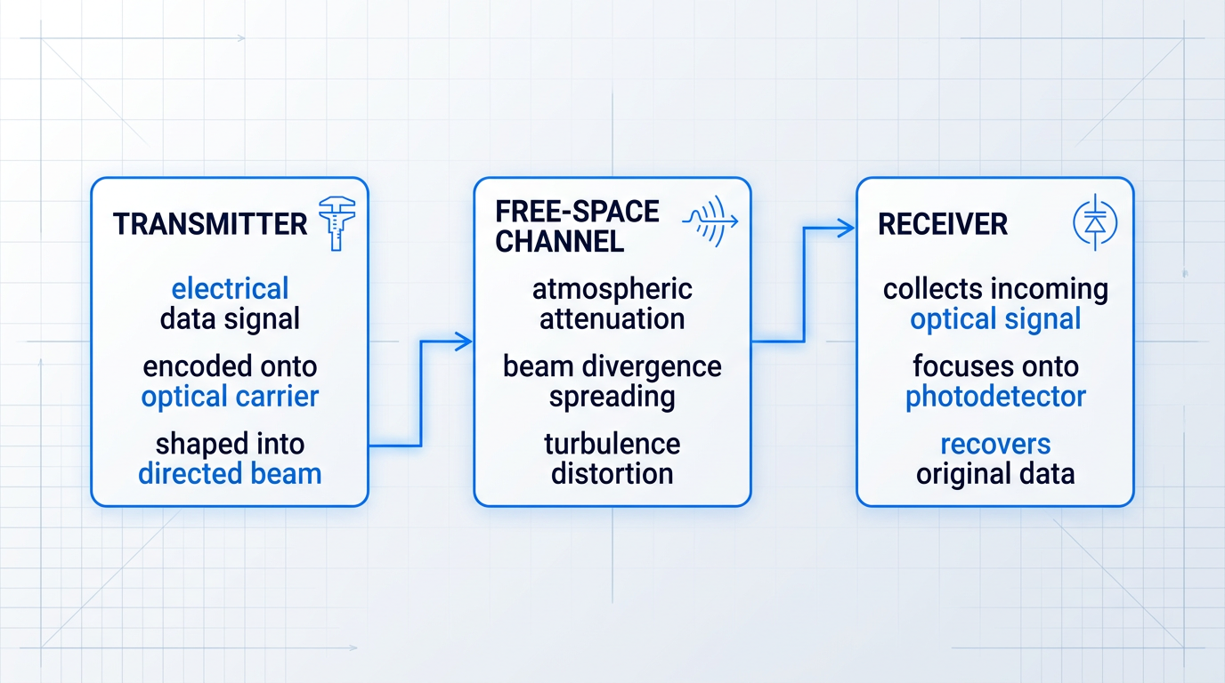
At its core, an FSO system decomposes into three elements: the transmitter (the optical source end), the free-space channel (the atmospheric propagation path), and the receiver (the destination end). The channel is not a passive conduit — it attenuates, distorts, and introduces turbulence — but the transmitter and receiver are the two ends that engineers actually design. The channel is the constraint they design around.
What the Transmitter Does
The transmitter's job is a functional chain: an electrical data signal is encoded onto an optical carrier, the resulting modulated light is shaped into a directed beam, and that beam is launched into free space toward the receiver.
Think of it as data-in, optical beam-out — the transmitter converts the electrical domain into the optical domain and then manages the geometry of how that optical energy is projected across the link.
What the Receiver Does
The receiver performs the mirror-image chain: it collects the incoming optical signal, focuses it onto a photodetector, converts the received optical power into an electrical current, and recovers the original data from that current.
Optical signal-in, data-out. The receiver's design is inseparable from the transmitter's because every choice the transmitter makes — how much power it launches, at what wavelength, with what beam geometry — determines what the receiver must be capable of detecting.
An FSO link's performance is determined by the transmitter and receiver as a matched pair. Specifying either end in isolation produces a system that works on paper and fails in the field.
Three Parameters That Bind Both Ends Together
Three system-level parameters govern the relationship between transmitter and receiver, and all three must be resolved jointly rather than assigned to one end.
- Link budget: The power accounting framework: transmitted power minus all losses must still exceed the receiver's minimum sensitivity threshold for the link to function.
- Wavelength: A system-level choice that cascades into detector selection, amplifier compatibility, eye-safety classification, and atmospheric penetration at both ends.
- Beam divergence: The angle at which the transmitted beam spreads — governing how much launched power actually reaches the receiver aperture at a given range.
The link budget is the shared accounting framework that makes this interdependence concrete: the transmitted power, minus geometric spreading loss, minus atmospheric attenuation, minus any pointing losses, must still arrive at the receiver above its sensitivity threshold. Every design decision at either end shifts this balance.
Wavelength is not a component specification — it is a system-level decision. FSO systems operate in the near-infrared spectrum, with two principal atmospheric transmission windows around 850 nm and 1550 nm where attenuation is low. The choice between them has cascading implications: it determines which photodetector technologies are suitable at the receiver, which optical amplifiers are compatible, what eye-safety class the transmitter falls into, and how well the signal penetrates haze and atmospheric turbulence.
Beam divergence is the fundamental geometric parameter of the link. A narrower divergence angle concentrates more transmitted power onto the receiver aperture, improving the link budget — but it demands correspondingly precise alignment between the two ends. A wider divergence tolerates pointing error and platform movement, but reduces received power density, which the receiver must compensate for. This is a trade-off engineered into the system, not a flaw to be minimised unconditionally.
Underpinning all three parameters is a non-negotiable physical requirement: FSO demands an unobstructed line-of-sight path between transmitter and receiver. Obstacles in the beam path cause link interruption, not just degradation. Alignment between the two ends is therefore not an installation inconvenience — it is an engineering problem that transmitter and receiver hardware are specifically designed to address, through beam width selection, active tracking systems, and adaptive optics.
With this system-level framework established, the sections that follow examine each element in depth — beginning with the transmitter stack: the laser source, modulation chain, driver electronics, and beam-forming optics that together determine what the receiver has to work with.
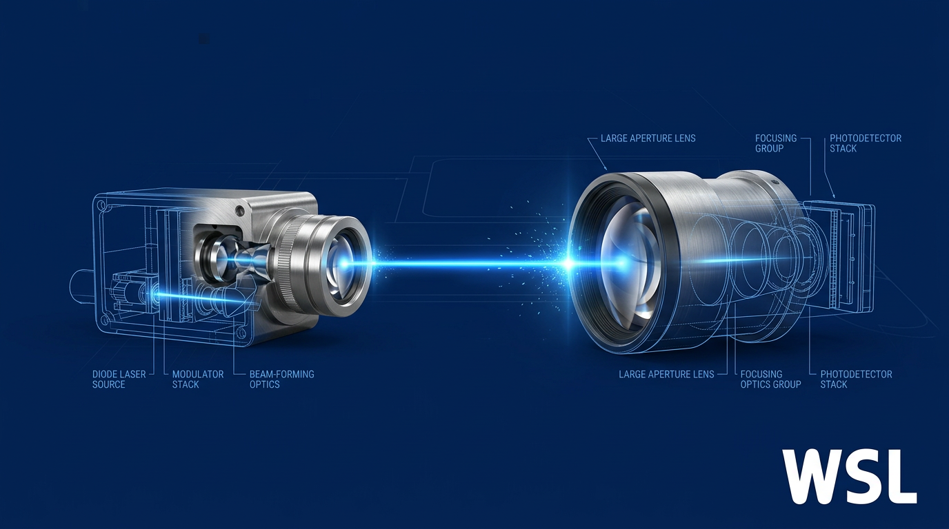
The FSO transmitter stack: laser, modulation, optics
Every photon that crosses an FSO link begins its journey inside the transmitter, passing through a chain of components that transform an electrical data signal into a precisely shaped optical beam. Understanding that chain — in functional order, and in terms of the engineering decisions each stage forces — is the foundation for understanding how FSO transmitter and receiver hardware is designed and why the choices at one stage constrain the choices at every stage that follows.
The chain begins at the optical source. Semiconductor laser diodes (LDs) are the dominant choice for FSO over light-emitting diodes (LEDs) for three reasons that each matter differently: coherence allows the output to be collimated into a tight, directed beam; directionality means power is concentrated along the link axis rather than radiated broadly; and high modulation bandwidth enables the data rates that make FSO commercially viable. LEDs, by contrast, produce incoherent, Lambertian emission — their broad divergence and limited modulation bandwidth make them unsuitable for the link distances and data rates that FSO is deployed to achieve.
Within the LD family, three device types are used in FSO systems, each associated with a specific wavelength window and a distinct performance profile.
- VCSELs at 850 nm: Vertical-Cavity Surface-Emitting Lasers offer low threshold currents, circular beam output, and high-speed direct modulation. Predominantly used in shorter-range FSO and data centre interconnects.
- Fabry-Pérot lasers at 1550 nm: Edge-emitting FP lasers are lower cost but exhibit multimode spectral output, making them better suited to moderate data-rate, shorter-reach 1550 nm applications.
- DFB lasers at 1550 nm: Distributed Feedback lasers produce single-mode, narrow-linewidth output, enabling higher data rates and longer reach where spectral purity is essential.
Once the optical source is selected, the signal must be encoded onto the light — and the method chosen here carries significant system-level consequences.
Direct modulation vs. external modulation
Direct modulation varies the laser's drive current in proportion to the data signal, encoding information as changes in optical output power. It is the simpler approach: fewer components, lower cost, and a more compact transmitter. The limitation is frequency chirp — when drive current changes rapidly, the carrier density inside the laser cavity fluctuates, which in turn shifts the refractive index and causes the emission wavelength to drift dynamically with each bit transition.
That chirp broadens the optical spectrum of each transmitted pulse. At high data rates or over longer links, the resulting spectral broadening degrades signal integrity and limits achievable reach. Sources confirm that direct modulation becomes problematic above roughly 10 Gbps, where chirp-induced effects impose a hard ceiling on transmission distance.
External modulation removes this constraint by operating the laser at a constant bias current, maintaining a stable, continuous-wave (CW) output, and then passing that output through a separate modulator — most commonly a Mach-Zehnder Modulator (MZM) — to impress the data signal onto the beam. Because the laser itself is never switched, chirp is largely eliminated, enabling higher data rates and longer reach. The trade-off is added system complexity, a higher component count, and the insertion loss introduced by the modulator element.
The choice between direct and external modulation is a deliberate engineering decision calibrated to the target data rate, link distance, and system cost budget: direct modulation suits shorter-range, lower-rate links where simplicity and cost efficiency dominate; external modulation is the architecture of choice where spectral purity and reach are the governing constraints.
Between the data source and the laser, the driver circuit performs a functional but essential role: it converts digital logic-level signals into the precise current waveform that drives the laser, ensuring the device is biased correctly above threshold and that the modulation current faithfully reproduces the data pattern without distortion.
Beam-forming optics: collimator and beam expander
The raw output of a laser diode diverges rapidly — edge-emitting devices in particular produce an asymmetric, elliptical output beam that would be useless for a kilometre-range link without optical shaping. The first element in the beam-forming chain is the collimator: a lens placed close to the laser facet that captures the diverging output and converts it into a well-collimated beam with a defined diameter and a small, manageable divergence angle.
The collimated beam then passes through a beam expander (BE), which increases the beam diameter while reducing its far-field divergence angle. The physics is straightforward: a beam expander with magnification factor m increases the exit beam diameter by a factor of m and reduces the divergence angle by the same factor. A 16× Galilean beam expander, for example, reduces divergence proportionally, so that the beam remains far more tightly collimated over a multi-kilometre link than a collimated-only output would.
The Galilean design — a negative lens followed by a positive lens, with no internal focal point — is particularly suited to FSO because it is compact, has no internal beam waist where high-power densities could cause damage, and is less sensitive to alignment errors than alternative configurations.
The engineering trade-off is explicit: a larger exit aperture reduces far-field divergence and increases received power density at the far end of the link, improving link margin. But a larger aperture means a physically larger and heavier optical head, which has implications for mounting, pointing, and system integration. The beam expander is not simply "bigger is better" — it is sized to the link distance and the acceptable aperture budget.
Narrower beam divergence concentrates power at the receiver and maximises link margin — but the resulting small beam footprint demands precise, stable alignment between transmitter and receiver. Wider divergence tolerates pointing error and simplifies alignment, but spreads power over a larger area, reducing received power density and degrading link margin. A fixed rooftop-to-rooftop link in a stable environment can tolerate tight divergence; a mobile or vibration-prone platform may require a wider beam to maintain link availability. This trade-off is the central geometric tension in FSO transmitter design.
Before modulation, an optional step in the transmitter chain is channel coding — adding structured redundancy to the data stream so that the receiver can detect and correct errors. Coding schemes improve link reliability under adverse atmospheric conditions, effectively buying additional margin against signal degradation without increasing transmit power.
Each of the laser types described here operates at a specific wavelength, and that wavelength choice is not merely an identifier — it determines eye-safety margins, atmospheric transmission characteristics, and compatibility with downstream optical components. The next section examines why wavelength selection has consequences that extend well beyond the laser source itself.
Wavelength selection: why 1550 nm dominates FSO transmitter design
The laser types covered in the previous section are not interchangeable — the wavelength they emit is a system-level decision that propagates through every downstream component choice, from the detector material at the receiver to the amplifier architecture in the transmitter chain.
FSO designers are not choosing from an open spectrum. The atmosphere imposes its own constraints, remaining relatively transparent only within a small set of near-infrared transmission windows where molecular absorption and scattering are minimised.
Four primary windows are relevant to FSO in the near-IR: approximately 850 nm, 1060 nm, 1250 nm, and 1550 nm — each characterised by atmospheric attenuation below 0.2 dB/km under clear conditions.
Why 1550 nm has become the dominant FSO wavelength
The most counterintuitive advantage of 1550 nm is that eye-safety regulations effectively confer a power advantage on it. At 850 nm, light passes through the cornea and lens and is focused onto the retina — concentrated by a factor of 100,000 — making it capable of causing permanent retinal damage before a person is even aware of exposure.
At 1550 nm, the light is absorbed by the cornea and lens before it can reach the retina, which means IEC and ANSI safety standards permit substantially higher transmitted power — approximately 50 times more than at 800 nm — while still meeting IEC Class 1M and ANSI Class 1 eye-safety classifications.
Because 1550 nm light is absorbed before reaching the retina, IEC and ANSI safety limits permit approximately 50 times more transmitted power at 1550 nm than at 800 nm — making 1550 nm not just the safer wavelength, but the higher-power, higher-margin choice.
That 50× power allowance translates directly into greater link margin, better penetration through fog and haze, and extended operational range — none of which is available to 850 nm systems operating under the same safety framework.
The second major advantage is the commercial ecosystem that 1550 nm inherits from the fibre-optic telecommunications industry: DFB lasers capable of 2.5 Gbps and beyond, EDFA optical amplifiers, WDM components, and high-speed modulators are all mass-produced and cost-competitive because of decades of fibre-optic investment — and FSO systems at 1550 nm can access this entire infrastructure directly.
The 850 nm window: lower cost, real constraints
The 850 nm window is not simply inferior — it has genuine engineering merits. VCSELs and silicon APDs are lower-cost and more mature than their 1550 nm counterparts, and for short-range, cost-sensitive, lower-data-rate applications the window remains a practical choice.
But the constraints are binding for high-performance deployments: the eye-safety limit caps transmit power at roughly 1/50th of what 1550 nm systems can legally launch, and commercial 850 nm components top out at approximately 622 Mbps — with minimal industry roadmap to extend that ceiling.
The table below compares the two dominant FSO wavelength windows across the axes that matter most to link design.
| Attribute | 850 nm window | 1550 nm window |
|---|---|---|
| Eye-safe permitted power (relative) | Baseline | ~50× higher (IEC Class 1M / ANSI Class 1) |
| Max data rate (commercial components) | ~622 Mbps | 2.5 Gbps widely available; 10 Gbps emerging |
| Laser source type | VCSELs (lower cost) | DFB / FP lasers (high-speed, telecom-grade) |
| Compatible detector material | Silicon APD | InGaAs APD |
| Optical amplifier compatibility | None (no mature amplifier ecosystem) | EDFA (C-band: 1530–1565 nm); SOA |
| WDM / scalability path | Limited; components not widely available | Full WDM ecosystem; straightforward scaling |
| Atmospheric attenuation (clear) | <0.2 dB/km | <0.2 dB/km |
Side-by-side comparison of 850 nm and 1550 nm FSO wavelength windows across eye-safety power limits, max data rate, component ecosystem, compatible detector material, and amplifier availability.
The clear-weather attenuation figures are nearly identical for both windows — the atmosphere does not strongly favour one over the other under benign conditions. The decisive divergence is in permitted transmit power, data-rate ceiling, and amplifier access: for high-bandwidth, long-range, or fog-prone deployments, 1550 nm wins on every axis that matters.
For cost-sensitive, short-range applications where 622 Mbps is sufficient and fog margin is not a design driver, 850 nm remains a legitimate engineering choice — but that design space is narrowing as data-rate demands rise.
The deeper point is that wavelength selection is a cascade: the choice made at the transmitter determines the detector material at the receiver (InGaAs for 1550 nm, silicon for 850 nm), the amplifier architecture available in the transmitter chain (EDFAs operate in the 1530–1565 nm C-band and are therefore exclusive to 1550 nm systems), and the eye-safety class governing maximum launch power.
There is also emerging research interest in mid-wave infrared (MWIR) wavelengths — typically 3–5 µm — where turbulence-induced scintillation is reduced at longer wavelengths and atmospheric absorption can be lower under certain conditions. Component maturity at MWIR (quantum cascade lasers, interband cascade lasers) remains far behind the 1550 nm ecosystem, and MWIR FSO is a research direction rather than a deployment-ready option.
EDFA compatibility is one of the most consequential 1550 nm advantages — and it is the subject of the next section, which examines how erbium-doped fibre amplifiers are integrated into the FSO transmitter chain and what link margin benefit they deliver in practice.
Optical amplification in FSO transmitters: the role of EDFAs
The fibre-optic telecommunications industry spent decades solving the optical amplification problem, and FSO systems can inherit that solution directly — no reinvention required.
An erbium-doped fibre amplifier (EDFA) is a short length of silica fibre whose core is doped with erbium ions (Er³⁺) and pumped by a laser diode at 980 nm or 1480 nm, establishing a population inversion that amplifies optical signals passing through it via stimulated emission.
The gain band spans the C-band (approximately 1530–1565 nm) and extends into the L-band (1565–1625 nm), with typical small-signal gains of 20 to 40 dB and saturation output powers of 20 dBm or more in booster configurations.
The EDFA as a post-amplifier in the transmitter chain
In an FSO transmitter, the post-amplifier stage sits between the modulated laser output and the beam-forming optics, boosting the signal before it is launched into free space.
This positioning reflects a deliberate engineering choice: the laser source is run at conservative drive currents — protecting linearity, lifetime, and signal quality — while the EDFA provides the high launch power the link budget demands.
The decoupling of laser operating point from output power is the key insight here: amplification becomes a design degree of freedom, not simply a power boost applied as an afterthought.
This is precisely the architecture used in published FSO system designs — a 10 Gbps OOK-modulated transmitter at 1550 nm, for example, uses a post-EDFA (with 25 dB gain and 5 dB noise figure) to boost the weak modulator output before the collimator and beam expander.
Why 1550 nm and EDFA compatibility are inseparable
As established in the wavelength selection discussion earlier in this guide, 1550 nm sits at the centre of the atmospheric transmission window that FSO systems exploit — and it maps precisely onto the C-band and L-band gain spectrum of the EDFA.
EDFAs are a mature, commodity technology refined over decades of fibre-optic telecommunications deployment: they are widely available, well-characterised, and cost-effective at commercial scale.
Choosing 1550 nm for an FSO system is therefore not only a wavelength decision — it unlocks an entire ecosystem of proven amplification hardware developed for terrestrial fibre networks and now directly transferable to free-space links.
How EDFA-boosted launch power improves link margin
Higher launch power from the post-EDFA directly increases the available link margin — the cushion between the transmitted signal and the receiver's sensitivity threshold.
That margin can be deployed in three distinct ways, depending on the system's priorities.
- Extended operating range: Greater launch power allows the signal to traverse longer distances before falling below the receiver sensitivity threshold, directly increasing link reach.
- Improved fog penetration: Higher power means the signal survives greater atmospheric attenuation before it is lost, giving the link more resilience during dense fog events.
- Atmospheric fading headroom: Excess margin absorbs the power drops caused by scintillation and turbulence-induced fading, maintaining a viable link during adverse conditions.
Engineers should treat these three deployments as a design trade-off: a link optimised for maximum range will spend its margin differently from one optimised for high availability in a fog-prone urban environment.
The broader point is that the EDFA gives the system designer a transmitter-side lever on the link budget equation — one that should be considered from the outset of link design, not only when a range problem is discovered after the fact.
Eye safety with EDFA-boosted 1550 nm transmitters
The natural concern when discussing high-power optical transmitters is eye safety — and it is a legitimate one that deserves a direct answer rather than a footnote.
The physical reason 1550 nm is safer than shorter wavelengths is that the cornea and lens absorb light at this wavelength before it can reach the retina, whereas light in the 850 nm range transmits through the eye's optics and can focus onto the retina at much lower power levels.
IEC 60825-1, the governing laser safety standard, reflects this physics: significantly more transmitted power is permitted at 1550 nm than at 850 nm before a system exceeds Class 1 (eye-safe) limits — one IEEE Spectrum source puts the ratio at approximately two orders of magnitude.
Because IEC 60825-1 permits substantially more transmitted power at 1550 nm than at 850 nm within the Class 1/1M limits — owing to corneal absorption that prevents retinal exposure — 1550 nm FSO transmitters can launch more power before leaving the eye-safe classes. Amplified watt-level EDFA transmitters go beyond those limits: they are Class 4 laser products that need engineering controls and site safety measures.
This means 1550 nm gives more launch power within the eye-safe classes than 850 nm, and EDFA amplification extends launch power further where the link budget demands it — at which point the transmitter becomes a Class 4 laser product.
Engineers designing EDFA-boosted transmitters for rooftop-to-rooftop terrestrial links, campus networks, or satellite ground stations should therefore plan for Class 4 engineering controls and site safety measures from the outset.
EDFAs at the receiver: a forward reference
The EDFA is not exclusively a transmitter-side tool: it can also be deployed as an optical preamplifier at the receiver, placed before the photodetector to boost the incoming signal prior to photodetection — a technique that has been demonstrated in FSO systems achieving sensitivities below −51 dBm.
That receiver-side application is covered in full in the next section, which examines the FSO receiver stack — the complementary half of the link that must be co-engineered with the transmitter to realise the performance the EDFA-boosted launch power makes possible.
Custom EDFAs Built for FSO Applications
Our EDFAs are tailored for free-space optical communications — delivering high average output power with on-demand modulation. View the product range or download the EDF-UL-10 datasheet to see the specifications.

The FSO receiver stack: aperture, optics, and photodetection
The transmitter launches a carefully shaped beam into free space; the receiver's job is to catch what survives the journey and turn it back into a reliable electrical signal. That process unfolds through a chain of components, each with its own engineering trade-offs — and the choices made at each stage directly determine whether the link closes or fails.
Collecting aperture: how much signal the receiver gathers
The first element the incoming beam encounters is the collecting aperture — a lens or telescope that intercepts a portion of the transmitted beam's cross-section and gathers its optical power into the receiver.
Aperture area is a first-order design decision: a larger aperture captures more of the beam's power, directly improving the received signal level and contributing to link margin.
The trade-off is real, however. Larger apertures add size, weight, and cost — and they are not always the right answer for every deployment environment.
There is a secondary benefit worth noting: larger apertures also provide aperture averaging, which reduces the intensity variance caused by atmospheric scintillation by spatially averaging over multiple coherence cells of the turbulent wavefront — a topic explored in depth in the atmospheric effects section.
Focusing optics: concentrating light onto the detector
Once the aperture has gathered the light, the focusing optics must concentrate it onto the active area of the photodetector — a region that typically spans tens to hundreds of micrometres in diameter for FSO-grade InGaAs APDs, and around 40 µm for high-speed InGaAs/InP PIN array pixels.
The lens system's role is to reduce the collected beam diameter to match the detector's active area, maximising the fraction of gathered power that actually reaches the photosensitive region.
The focusing optics design also governs the receiver's field of view (FOV): a narrower FOV rejects more background solar radiation, reducing shot noise from ambient light — but it demands tighter alignment between transmitter and receiver.
This is a genuine design tension: maximising background light rejection through a narrow FOV trades directly against alignment tolerance, which has implications for the pointing and tracking system discussed later.
Photodetector choice: PIN photodiodes versus APDs
Detector selection is a foundational receiver design decision, not a commodity choice — the photodetector type determines the receiver's sensitivity ceiling, noise floor, circuit complexity, and operating voltage requirements.
The two main detector types used in FSO receivers are PIN photodiodes and avalanche photodiodes (APDs), and they differ fundamentally in how they convert optical power to electrical current.
| Parameter | PIN Photodiode | Avalanche Photodiode (APD) |
|---|---|---|
| Internal gain mechanism | None — photocurrent is directly proportional to incident optical power (M = 1) | Avalanche multiplication: primary photocurrent amplified internally; typical M = 10–30 for InGaAs FSO receivers |
| Typical bias voltage | Low; generally below 10–30 V depending on device | Significantly higher: InGaAs APDs at 1550 nm typically 36–75 V operating voltage; silicon APDs at 850 nm require 100–300 V or more |
| Responsivity at 1550 nm (unity gain) | ~0.8–1.0 A/W for InGaAs PIN devices | ~0.9–1.05 A/W at unity gain (M = 1) for InGaAs APDs; effective responsivity multiplied by gain M in operation |
| Noise characteristics | Thermal noise dominant; shot noise scales with signal current only; no excess noise factor | Shot noise scales with M; excess noise factor F(M) adds stochastic multiplication noise — F(M) typically 3–5 for M = 10 in InGaAs APDs |
| Dark current | Low; simpler to manage | Higher multiplied dark current (I_dm); requires careful bias and temperature management |
| Circuit complexity and cost | Simpler circuit; lower-voltage power supply; lower cost | Higher-voltage bias supply required; temperature compensation circuit often needed; higher cost |
| Preferred FSO application | Short-to-medium range links with adequate received power; cost-sensitive deployments | Long-range or high-sensitivity links where received signal is weak and internal gain justifies added complexity |
Direct comparison of PIN photodiode and APD across the key receiver design axes, using specific data from manufacturer datasheets and peer-reviewed sources.
The practical heuristic for FSO receiver design is straightforward: reach for an APD when the link is long, the received signal is weak, and the sensitivity budget is tight — and accept the higher bias voltage and circuit complexity as the price of that gain.
PIN photodiodes are the right choice when signal levels are adequate, when cost and simplicity are priorities, or when the required data rate pushes against APD bandwidth limitations at high gain settings.
The wavelength context established earlier in this guide is directly relevant here: as covered in the wavelength selection section, 1550 nm is the dominant FSO wavelength, and InGaAs APDs are the corresponding dominant detector choice at that wavelength — silicon APDs are used at 850 nm, where their higher required bias voltage (100–300 V) is offset by their lower excess noise coefficient.
It is also worth noting that an EDFA can be deployed as a receiver-side optical preamplifier — placed before the photodetector to boost the incoming signal optically before it reaches the detector, improving effective sensitivity without relying solely on APD gain.
Photodetector responsivity and wavelength dependence
Responsivity is the efficiency with which a photodetector converts incident optical power to electrical current, measured in amperes per watt (A/W) — it determines how much photocurrent is generated per unit of received optical power.
Responsivity varies with wavelength and semiconductor material. InGaAs detectors are optimised for the 1550 nm band: peer-reviewed measurements confirm typical unity-gain responsivity of approximately 0.9–1.05 A/W for InGaAs APDs at 1550 nm, with values around 1.0 A/W commonly cited for FSO receiver front-end design.
Silicon detectors peak in the shorter near-infrared range: conventional silicon photodiodes achieve a maximum responsivity of approximately 500 mA/W (0.5 A/W) around 880 nm, making them well-matched to 850 nm FSO systems but unsuitable at 1550 nm.
Germanium offers broader spectral coverage spanning both 1300 nm and 1550 nm, but carries a higher dark current penalty — a trade-off that limits its use in high-sensitivity FSO receivers where noise floor matters.
Signal conditioning: TIA, filtering, and amplification
The photodetector's output is a current signal — small, and not directly usable by downstream data recovery circuitry.
The transimpedance amplifier (TIA) is the critical first active stage: it converts the photodetector's current output into a voltage signal by passing the current through a feedback resistor, producing a voltage proportional to the photocurrent.
TIA design choices have a direct impact on receiver performance — the feedback resistance sets both the transimpedance gain and the noise contribution, while the amplifier's bandwidth must be matched to the target data rate.
A low-pass filter following the TIA reduces thermal noise and out-of-band background noise contributions, limiting the noise bandwidth to what the signal actually occupies.
Subsequent amplification stages bring the conditioned signal to a level suitable for the data recovery block — typically a comparator or clock-and-data recovery (CDR) circuit that makes the final bit decisions.
Noise sources and receiver sensitivity
Three principal noise sources determine how sensitive the receiver can be — that is, how weak a signal it can reliably detect at a target bit error rate.
- Shot noise: Fundamental quantum noise from the discrete arrival of photons and generation of electron-hole pairs. Scales with signal current and, for APDs, with multiplication gain M.
- Thermal noise (Johnson noise): Generated in the load resistor and TIA input. Independent of signal level; typically dominant in PIN-based receivers where no internal gain is present.
- Dark current noise: Leakage current flowing without any illumination. Contributes a noise floor that limits sensitivity; elevated in APDs due to multiplied dark current, and in germanium detectors.
The TIA's feedback resistor is chosen to balance these contributions: a higher load resistance reduces thermal noise but restricts bandwidth, while a lower resistance widens bandwidth at the cost of a higher noise floor — the optimum depends on the target data rate.
For a 1 Gbps InGaAs APD receiver front-end, a typical TIA input-referred noise density of around 2.1 pA/√Hz has been reported in the literature, with transimpedance resistance on the order of tens of kilohms.
Receiver sensitivity — the minimum optical power at which the link can reliably recover data — is not a property of the detector alone. It emerges from the combined interaction of detector responsivity, APD multiplication gain (if used), shot noise, thermal noise, dark current, and TIA design. Improving any one of these in isolation will not close a link that is fundamentally limited by another; the receiver must be engineered as a system.
With the receiver stack now understood — aperture collection area, detector type and responsivity, and the noise-limited sensitivity floor — the next section brings the two ends of the link together: the link budget shows how transmitter output power and receiver sensitivity are balanced against each other to determine whether a given FSO deployment will work.
How transmitter and receiver design decisions connect
The transmitter stack and receiver stack have been treated separately up to this point — but every design choice made at either end is ultimately answerable to a single shared calculation: the link budget. This is where those two bodies of engineering finally meet.
A link budget is a power accounting framework that determines whether a link closes — whether the signal arriving at the receiver exceeds the minimum detectable signal, or sensitivity threshold, that the photodetector and signal conditioning chain can reliably process.
Expressed as a relationship, it takes the form: received power = transmitted power + transmitter gain − geometric loss − atmospheric attenuation − system losses. The surplus of received power above the receiver's sensitivity threshold is the link margin — the quantity that determines whether the link survives real-world conditions.
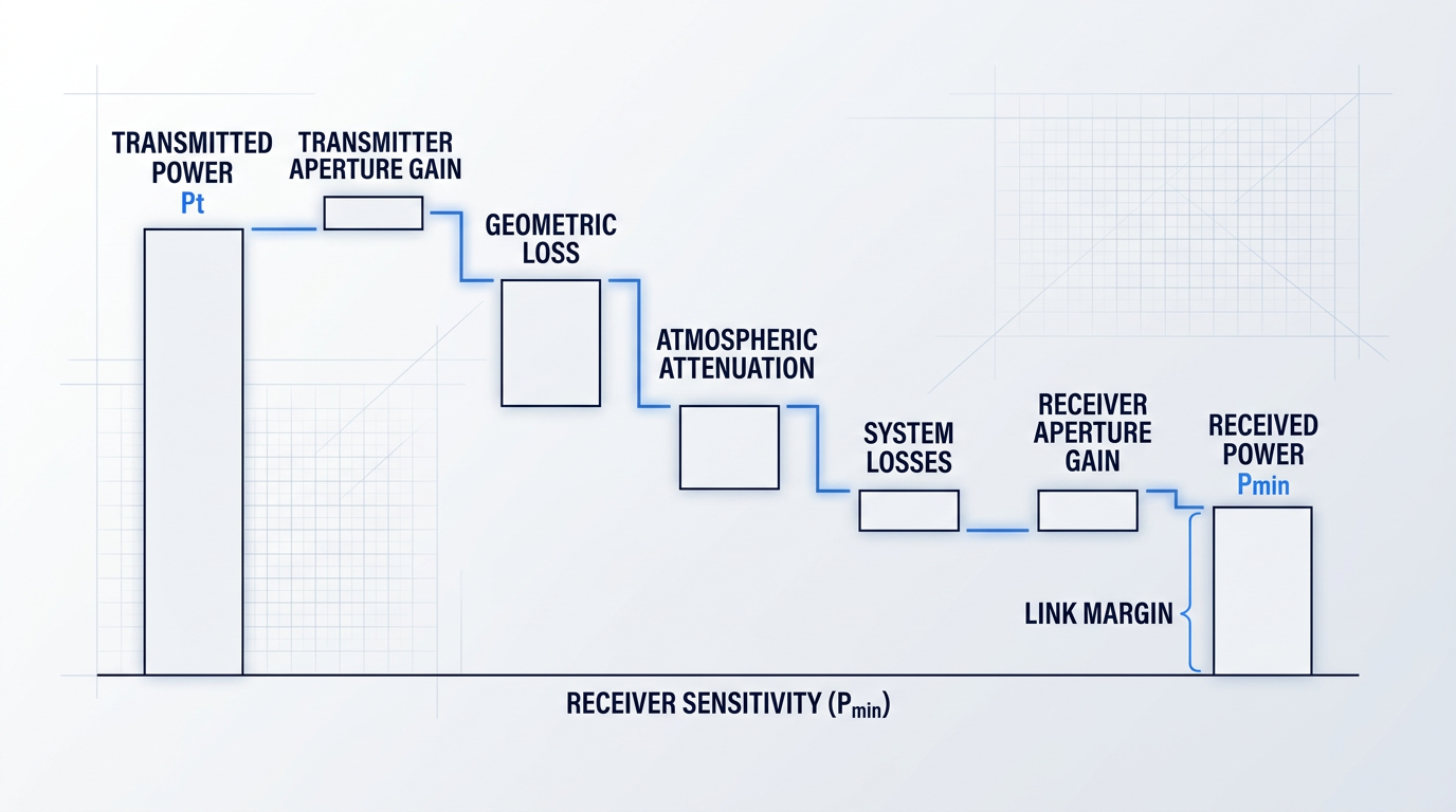
Reading that diagram left to right, the transmitted power is the starting point — set by the laser source and boosted, where applicable, by an EDFA post-amplifier as discussed in the amplification section. Each subsequent bar represents a loss that the designer must account for before the signal reaches the photodetector.
The gap between the received power bar and the sensitivity threshold line is the link margin. A link that closes comfortably in clear air may fall below the threshold during a period of dense fog or heavy attenuation — which is precisely why margin is the central design variable, not merely an afterthought.
| Budget Term | What It Represents | Link End | Gain or Loss |
|---|---|---|---|
| Transmitted power (Pt) | Optical power launched into free space by the laser source, including any EDFA amplification | Transmitter | Gain |
| Transmitter aperture gain (Gt) | Beam collimation quality; tighter divergence concentrates more power toward the receiver | Transmitter | Gain |
| Geometric (free-space) loss (Lfs) | Power lost to beam spreading over distance; grows with link length and divergence angle | Channel | Loss |
| Atmospheric attenuation (La) | Exponential signal decay due to absorption and scattering by fog, haze, rain, or aerosols | Channel | Loss |
| System losses (Ls) | Optical insertion losses, pointing errors, window contamination, and component ageing | System | Loss |
| Receiver aperture gain (Gr) | Collecting area of the receive lens or telescope; larger aperture captures more of the beam | Receiver | Gain |
| Receiver sensitivity (Pmin) | Minimum detectable signal at the photodetector — the floor against which received power is compared | Receiver | Reference threshold |
| Link margin (M) | Surplus of received power above Pmin; the operational headroom available for adverse conditions | System | Design target |
Maps each link budget term to its physical meaning, which end of the FSO link it belongs to, and whether it contributes a gain or a loss — connecting the equation to the hardware components covered in preceding sections.
Every row in that table maps directly to a component decision covered in the preceding sections. The transmitter aperture gain reflects beam expander quality and divergence control; the receiver aperture gain reflects the aperture sizing trade-off discussed in the receiver stack section; and the receiver sensitivity reflects the photodetector choice — PIN versus APD — along with the signal conditioning chain.
This is the co-engineering reality of FSO design: a decision to reduce beam divergence at the transmitter improves transmitter aperture gain and reduces geometric loss, but it simultaneously tightens the alignment tolerance the receiver must maintain. No term in the budget belongs exclusively to one end of the link.
Geometric loss and aperture gain
Geometric loss, sometimes called free-space path loss, arises because a diverging beam illuminates an area that grows with the square of distance — and the receiver aperture captures only the fraction of that area it physically subtends.
A narrower beam divergence angle concentrates more power within the receiver's field of view, reducing geometric loss. This is the transmitter-side aperture gain: a well-collimated beam from a large-aperture transmit telescope behaves like a higher-gain antenna, directing more energy toward the receiver rather than spreading it into the surrounding atmosphere.
At the receiver end, a larger collecting aperture intercepts a greater fraction of the arriving beam, contributing receiver aperture gain as a partial offset to geometric loss. The divergence trade-off explored in the transmitter section and the aperture sizing discussion in the receiver section are, in link budget terms, two sides of the same geometric equation.
Atmospheric attenuation: the variable design constraint
Atmospheric attenuation follows Beer-Lambert's law: signal power decays exponentially with path length at a rate governed by the attenuation coefficient, which depends on wavelength, ambient visibility, and the dominant scattering mechanism — whether molecular absorption, Mie scattering from aerosols and fog droplets, or geometric scattering from rain.
For the link budget, atmospheric attenuation is a design input, not a background fact. The designer must estimate the worst-case attenuation coefficient for the deployment environment — a coastal site prone to sea fog presents a fundamentally different constraint than an arid inland corridor — and the link margin must be sized to accommodate it.
This is where wavelength selection intersects with the link budget directly. Operating at 1550 nm, within the near-infrared atmospheric transmission window, reduces the baseline attenuation coefficient under clear and moderate conditions. Under dense fog, however, attenuation can reach tens of dB per kilometre regardless of wavelength, which is why margin — not wavelength optimisation alone — is the primary engineering response to severe atmospheric conditions.
The two levers: transmit power and receiver sensitivity
Given the link budget equation, the designer has two fundamental levers for increasing margin: raise the received power, or lower the sensitivity threshold against which it is compared.
- Transmit power: Boosting launch power via an EDFA post-amplifier directly raises received power and margin, without any change to the receiver or channel.
- Receiver sensitivity: Selecting an APD over a PIN photodiode, or adding an optical preamplifier before the detector, lowers the minimum detectable signal and increases effective margin without raising transmitted power.
These levers are complementary, not alternatives. Increasing transmitted power carries cost and eye-safety implications — higher launch power demands more rigorous hazard classification and may constrain deployment in populated areas. Improving receiver sensitivity adds complexity and cost at the receive end. In practice, well-engineered FSO systems apply both levers in proportion to the link's range and availability requirements.
A link budget that closes under clear-sky conditions is not sufficient. The margin must exceed the worst-case atmospheric attenuation at the deployment site — not the average — to guarantee the specified link availability.
Link availability is the operational metric that the link budget ultimately determines: the percentage of time the link operates above the receiver sensitivity floor, expressed as a figure such as 99.9% or 99.99%.
Availability is set by the relationship between the link margin and the statistical distribution of atmospheric attenuation at the deployment location. A margin that exceeds the attenuation experienced during 99.9% of hours at a given site will deliver 99.9% availability — making margin not a vague safety buffer but a precisely specified engineering parameter tied to a measurable site characteristic.
Atmospheric attenuation, however, is not the only impairment competing for that margin. Turbulence introduces rapid, stochastic intensity fluctuations — scintillation and beam wander — that impose their own fading events on top of the steady-state attenuation the link budget captures here. The next section examines how transmitter and receiver design choices address those turbulence-driven effects specifically.
Atmospheric impairments and how FSO design responds
The atmospheric loss terms in the link budget fall into two fundamentally different categories — and that distinction is not academic: it determines which end of the FSO link carries the engineering burden of mitigation, and which hardware choices actually move the needle on link reliability.
Attenuation (from fog, haze, rain, and aerosols) is a power-loss effect governed by Beer-Lambert exponential decay: the beam simply loses energy as it propagates, with the extinction coefficient driven by particle size distribution and visibility. Turbulence effects — scintillation, beam wander, and wavefront distortion — arise from spatially and temporally varying refractive index along the path, driven by temperature gradients and wind shear; they do not simply absorb the beam but redistribute and distort it.
These two categories call for fundamentally different engineering responses, and a designer who conflates them risks applying the wrong toolkit to the wrong problem.
Scintillation and aperture averaging
Scintillation is the rapid, random intensity fluctuation at the receiver caused by turbulent eddies that focus and defocus the beam as it propagates — a phenomenon quantified by the scintillation index, the normalised variance of received irradiance.
Critically, scintillation does not change the average received optical power; it induces temporal variations in the instantaneous power that can drive the signal below the receiver sensitivity threshold even when the mean power is comfortably above it — making turbulence a link-reliability issue, not merely a link-budget one.
The atmospheric turbulence coherence time — the timescale over which the channel gain remains effectively constant — is on the order of 1–10 ms, meaning individual fades persist long enough to corrupt bursts of data at typical symbol rates.
The deliberate receiver-side response is aperture averaging: a larger receive aperture spatially integrates over many turbulent eddies simultaneously, so the intensity fluctuations across the aperture partially cancel out, reducing the variance of received intensity — quantified by the aperture averaging factor.
Research confirms that significant scintillation reduction is achievable through aperture averaging, particularly under strong turbulence conditions; the optimal aperture size is closely related to the turbulence coherence width (the Fried parameter, r₀), with apertures sized near r₀ offering the best balance between mean received power and fading variance.
The trade-off is real: larger apertures collect more signal and suppress scintillation variance, but they add size, weight, and cost to the receiver terminal — this is a deliberate engineering decision, not a free benefit of simply going bigger.
Beam wander: centroid displacement and its consequence
Beam wander is a distinct turbulence phenomenon that must not be conflated with scintillation: where scintillation is intensity fluctuation (the beam arrives, but its power varies randomly), beam wander is centroid displacement — turbulence causes the beam's centre to drift randomly in the receiver plane.
If the wander amplitude exceeds the receiver's aperture radius or field of view, the beam misses the receiver entirely — a pointing-loss effect that can drop the link even when instantaneous beam power is adequate.
Beam wander is more pronounced over longer path lengths and under stronger turbulence, and it motivates both the transmitter-side diversity strategy described below and the active tracking systems that will be covered in the next section.
Transmit diversity: the transmitter-side turbulence response
Transmit diversity — implemented as a MISO (Multiple Input Single Output) configuration — is the primary transmitter-side engineering response to turbulence-induced fading.
Multiple spatially separated transmit apertures each illuminate the receiver from a slightly different path through the turbulent atmosphere, producing intensity fluctuations at the receiver that are spatially uncorrelated; when uncorrelated, those fluctuations partially average out, improving the statistical reliability of the received signal.
For the fades to be genuinely uncorrelated, the spatial separation between transmit apertures must exceed the turbulence coherence length — characterised by the Fried parameter r₀, which ranges from roughly 2 cm under strong turbulence to over 20 cm under weak conditions at ground level.
This is a transmitter architecture decision, not a simple power increase: adding a second aperture at insufficient separation produces correlated fades and delivers little diversity gain, while correct spacing yields statistically independent paths that the receiver combines to maintain link availability.
Adaptive optics: high-performance wavefront correction
Adaptive optics (AO) is a more sophisticated receiver-side mitigation targeting turbulence-induced wavefront distortion directly, rather than averaging over it.
In an AO-enabled FSO receiver, a wavefront sensor — typically a Shack-Hartmann sensor — measures the phase distortions introduced by the turbulent atmosphere in real time; a control unit then computes corrective commands that are applied to a deformable mirror or spatial light modulator, reshaping the incoming wavefront before it reaches the photodetector.
This closed-loop process restores the beam's planar wavefront profile, improving coupling efficiency, reducing scintillation, and stabilising received signal quality — the same principle used in large ground-based astronomical observatories to correct for atmospheric seeing.
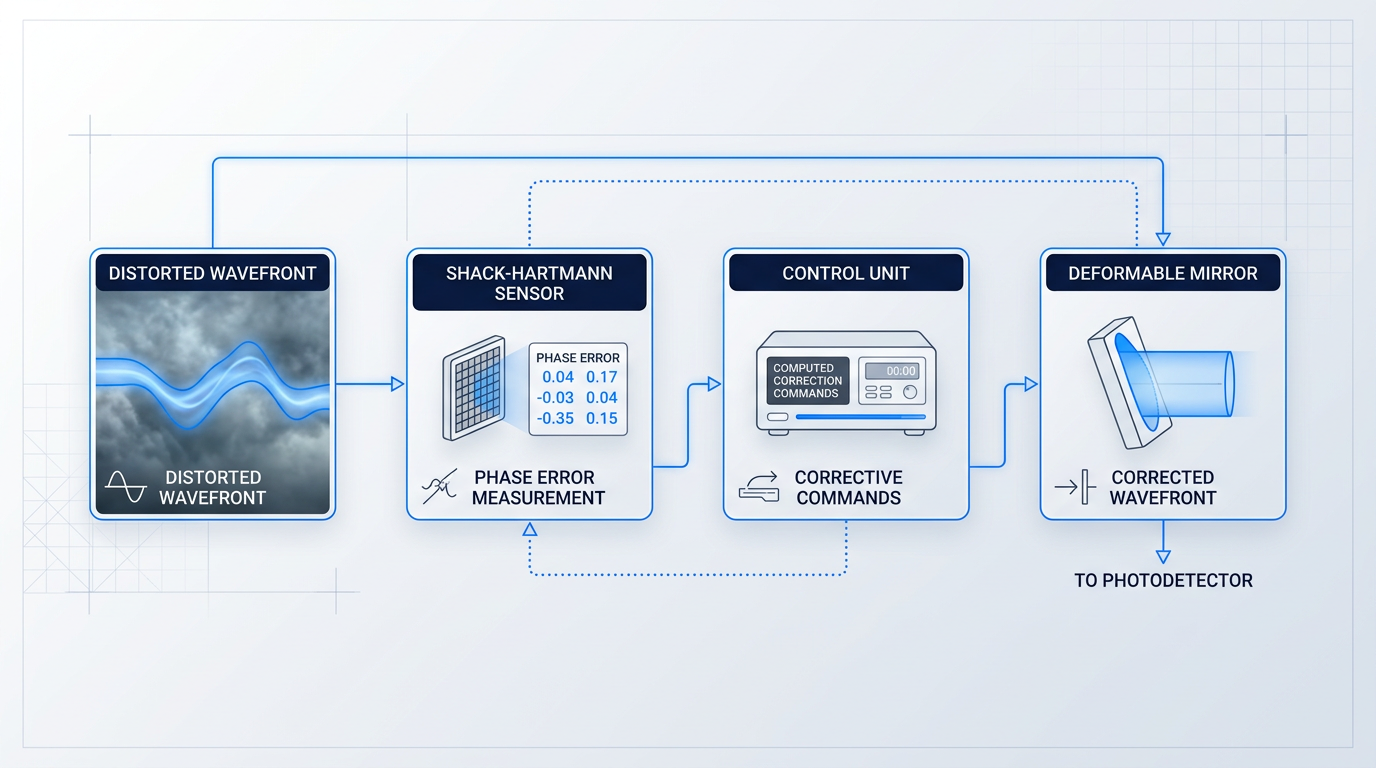
AO is increasingly relevant for high-performance FSO ground stations — particularly satellite-to-ground links, where turbulence (rather than fog) is the dominant impairment and where the complexity and cost of AO are justified by the performance requirements.
For shorter-range terrestrial links, AO is not typically deployed: it is a higher-complexity, higher-cost solution than aperture averaging, and the dominant impairment in those scenarios calls for a different response entirely.
For most building-to-building and last-mile FSO deployments, fog attenuation is the primary design constraint — not scintillation or beam wander. Dense fog can impose attenuation exceeding 100 dB/km, and the engineering response is sufficient link margin: high transmitter launch power (including EDFA boosting) combined with a large receiver aperture that captures more of the attenuated signal. Adaptive optics addresses the wrong problem for this scenario.
The fSONA engineering literature is direct on this point: fog presents the single greatest challenge for terrestrial FSO, and system design begins with fog statistics for the deployment location — determining what attenuation level must be accommodated to achieve a target availability, then sizing link margin accordingly.
Turbulence effects are real in terrestrial links but secondary: the practical response is not adaptive optics but rather the margin headroom built into the link budget through transmitter power and receiver aperture area — both of which were established as primary design levers in the transmitter and receiver stack sections earlier in this guide.
Beam wander, however, does not yield to link margin alone — it requires active pointing correction, which brings us to the hardware that addresses it directly: the pointing, acquisition, and tracking systems that form the subject of the next section.
Alignment, Pointing, and Tracking in FSO Systems
A beam divergence of 1 mrad produces a footprint roughly one metre across at a kilometre range. That sounds manageable — until you consider that platform vibration, thermal expansion of a rooftop mount, or wind-induced sway in a tall building can shift the beam centroid by enough to miss the receiver aperture entirely. Alignment in FSO is not a one-time installation task; it is a continuous physical battle that the hardware must win, repeatedly, on a millisecond timescale.
The engineered response to this challenge is the PAT subsystem — Pointing, Acquisition, and Tracking — a hardware layer built into the FSO transceiver that manages beam alignment autonomously from initial link establishment through sustained data transmission.
The two-phase PAT process
PAT operates in two sequential phases, each with distinct optical and mechanical requirements.
- Coarse acquisition: A wider-divergence beacon beam scans for the remote terminal. The broader footprint increases the probability of initial detection before the narrow data beam is engaged.
- Fine tracking: Once lock is established, the narrow data beam activates and a closed-loop feedback circuit makes continuous small corrections to maintain precise alignment in real time.
Critically, both phases are automated hardware functions — the handoff from acquisition to tracking is not operator-initiated. The feedback loop in the tracking phase runs continuously; it is not a calibration step that completes and stops.
Sources of pointing error the PAT system must correct
On the transmitter side, mechanical vibration of the platform — whether from HVAC equipment on a rooftop, aircraft engine noise, or structural resonance — causes the transmitted beam centroid to wander randomly at the receiver, reducing the fraction of power falling within the receiver aperture.
On the receiver side, angle-of-arrival (AoA) fluctuations vary the direction from which the incoming beam reaches the aperture, driven by both atmospheric turbulence and motion of the receiving platform itself. Both error sources are independent and must be compensated simultaneously by the PAT system.
Gimbal-based tracking and its engineering limits
Traditional PAT systems use motorised gimbals to physically reorient the transceiver head, keeping the beam on target through mechanical rotation. Gimbals are mature and well-understood, and they can achieve the angular precision FSO links demand.
Their limitations become significant in demanding deployment contexts. Finite slew rates constrain how quickly the system can respond to rapid pointing excursions. In airborne and space applications, the SWaP penalty — size, weight, and power — of a motorised gimbal assembly is a genuine system-level cost. Mechanical wear over operational lifetime is an additional factor. These constraints are not a failure of gimbal technology; they are the engineering motivation for alternatives.
Optical phased arrays (OPAs) represent the most actively developed alternative. An OPA steers the beam electronically by controlling the relative phase of multiple emitters across a chip-scale aperture — no moving parts, and in principle capable of steering speeds orders of magnitude faster than any mechanical system.
The key trade-off that has historically limited OPA adoption in FSO links is field-of-view versus beam quality: achieving a wide steering range tends to degrade beam quality through elevated sidelobe levels and increased divergence, which directly erodes the link budget. OPAs remain a promising and actively researched technology, but they are not yet a universal replacement for gimbal-based PAT in production FSO hardware.
The PAT subsystem shapes decisions across the entire FSO hardware pair — beam divergence, aperture geometry, detector field of view, and mounting structure all carry PAT requirements embedded in them from the design stage. Treating alignment as a deployment problem rather than a design problem is the root cause of most FSO link reliability failures.
Dynamic divergence control across the link lifecycle
Some FSO systems extend the PAT design philosophy to beam divergence itself, deliberately widening divergence during acquisition to increase the probability of finding the remote terminal, then narrowing it for data transmission to maximise received power density.
This is achieved through variable-focus lens assemblies or dedicated divergence control modules integrated into the transmitter optics. As established in the transmitter stack discussion earlier in this guide, divergence is a controlled parameter — and the PAT lifecycle is one of the clearest demonstrations of why that controllability matters in practice.
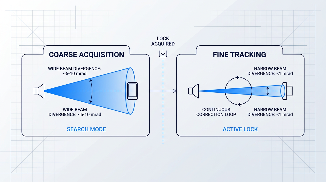
In a full-duplex FSO link, the alignment challenge doubles: the PAT system at each end must simultaneously track the other end's transmitter, and the mechanical and optical coupling between the two link directions must be accounted for in the hardware pair design.
With the PAT subsystem understood as a hardware discipline in its own right, the next question is how transmitter-receiver pairs are arranged for full-duplex operation in practice — and how the design trade-offs covered throughout this guide manifest across specific deployment environments.
Duplex FSO Links and Real-World Applications
All of the transmitter and receiver hardware covered in this guide ultimately comes together in one physical reality: a deployed FSO link, where each node is simultaneously a transmitter and a receiver, and both directions of traffic flow at once.
In a full-duplex point-to-point FSO system, each node houses a complete transmitter stack and a complete receiver stack. The transmitter at Node A is optically paired with the receiver at Node B, and the transmitter at Node B is paired with the receiver at Node A — two pipes running in opposite directions, forming a single bidirectional link.
To prevent the outgoing beam from interfering with the incoming signal, the two directions typically use physically offset transceiver apertures, separate wavelengths, or a combination of both. This separation is not incidental — it is a deliberate design constraint that shapes the mechanical and optical layout of each node.
As covered in the alignment and tracking discussion, the PAT system at each end must track the opposite node's transmitter, which means the two ends' tracking loops are inherently coupled. Duplex hardware design cannot treat the transmit and receive functions as independent — they share a pointing reference and must be co-aligned as a unit.
Every deployed FSO link consists of two transmitter-receiver pipes running in opposite directions simultaneously. The hardware at each node must accommodate both functions, and the PAT systems at both ends are coupled by design.
With that physical arrangement established, the question becomes: which design choices matter most in a given deployment? The answer shifts substantially depending on the application category.
Terrestrial last-mile and building-to-building links
Building-to-building FSO is the most widely deployed application context, with typical link spans running from roughly 300 m to a few kilometres across rooftops, building facades, and communication towers.
At these ranges, fog is the dominant impairment — not turbulence. The link budget must be sized against the worst expected visibility at the specific deployment site, which is a real design input that varies considerably by geography and season.
Because both ends are fixed structures, initial installation can align the transceivers mechanically, and the PAT system then handles fine correction against thermal drift and building vibration — a considerably simpler tracking problem than mobile or satellite applications present.
The link budget discussion from earlier in this guide applies directly here: the designer must know the local fog statistics to size transmit power and receiver aperture for the required link availability. At 1550 nm, EDFA-boosted transmitters can provide the additional margin needed to sustain the link through heavy fog events that would otherwise cause outages.
High-bandwidth backhaul and metro network extensions
FSO occupies a practical niche in cellular backhaul, metro network extensions, and enterprise campus connectivity — scenarios where fibre installation is too slow, too disruptive, or too costly to justify for a medium-range connection.
The core value proposition in these contexts is data rate. FSO systems operating at 1550 nm with high-speed external modulation can reach Gbps to multi-Gbps throughputs, placing them genuinely in contention with fibre for links in the sub-10 km range.
This is where the commercial ecosystem advantage of 1550 nm, discussed in the wavelength selection section, is most directly exploited: DFB laser sources, EDFAs, WDM-compatible components, and high-bandwidth InGaAs photodetectors are all mature, volume-manufactured products drawn directly from the fibre-optic telecommunications industry.
High-bandwidth backhaul also places the most demanding requirements on the receiver's signal conditioning chain — high-speed photodetectors and low-noise transimpedance amplifiers, as covered in the receiver stack discussion, must be matched to the modulation format chosen at the transmitter to meet the availability SLA the application demands.
Satellite ground link applications
Satellite ground links represent a fundamentally different engineering problem from any terrestrial FSO scenario, and the contrast is worth making explicit.
The dominant impairment shifts from fog to atmospheric turbulence, because the optical signal passes through the turbulent lower atmosphere at an oblique angle over path lengths that range from tens of kilometres for LEO satellites to much greater distances for GEO orbits.
Geometric free-space loss at these distances is enormous, which makes optical amplification at both ends of the link non-negotiable. EDFA post-amplifiers at the transmitter push launch power to the limit the link budget demands; EDFA preamplifiers at the receiver lift the extremely weak received signal above the detector noise floor before photodetection — exactly the dual-amplification architecture covered in the EDFA and receiver stack sections.
Beam divergence must be held to sub-milliradian levels to limit geometric spreading over these distances, and PAT precision requirements are correspondingly far tighter than anything a terrestrial link imposes.
On the receiver side, the turbulence mitigation techniques discussed in the atmospheric effects section — aperture averaging and adaptive optics — are especially critical here, because turbulence-induced fading is the primary reliability threat, not fog attenuation.
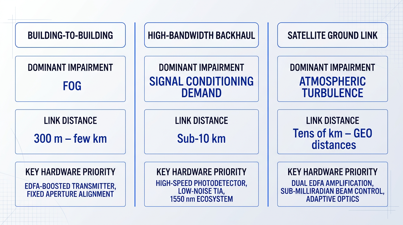
Across all three application categories, the pattern is consistent: the application context determines which design variables carry the most weight, not the hardware catalogue in isolation.
A terrestrial last-mile link is optimised for fog margin and installation simplicity. A high-bandwidth backhaul link is optimised for modulation speed and spectral ecosystem compatibility. A satellite ground link is optimised for amplification chain design, turbulence resilience, and sub-milliradian beam control — each drawing on a different subset of the transmitter-receiver engineering covered throughout this guide.
That application-driven design logic is the thread running through every section of this guide, and it points toward a broader principle: the right FSO system is not the one with the best individual components, but the one whose transmitter and receiver are co-engineered as a matched system for the specific link it must close.
See How Our FSOC Technology Works in Practice
Our EDF-UL-10 is a 10 W erbium-doped fibre amplifier for optical ground-station uplinks and beacons, carrying the tracking beacon and uplink data in a single beam. Explore the full offering or speak with an expert about your link requirements.

Conclusion
Designing FSO transmitter and receiver hardware as a system
The discipline that runs through every section of this guide is the same: FSO transmitter and receiver hardware is a co-engineered system, and treating either end as an independent specification exercise is where link performance problems begin.
Wavelength shapes the entire link; beam divergence is a calibrated choice, not a default; aperture and detector selection are foundational decisions, not finishing touches.
Which of those trade-offs matters most depends entirely on where and how the link is deployed — and that is where the real engineering work starts.
FSO transmitter and receiver: frequently asked questions
Practical answers to common questions about FSO transmitter and receiver hardware, component specifications, and design trade-offs — each written to stand alone without requiring prior reading of the guide.
FSO transmit power is primarily constrained by eye-safety regulations under IEC 60825-1. At 850 nm, allowable power is relatively low because the eye's optics focus that wavelength directly onto the retina, concentrating the beam to a damaging intensity. At 1550 nm, the cornea and lens absorb the light before it reaches the retina, which means Class 1 limits are approximately 50 times higher than at 850 nm. This is the principal reason 1550 nm dominates modern FSO transmitter design. Beyond the laser source itself, EDFA (erbium-doped fibre amplifier) boosting allows 1550 nm systems to amplify the modulated signal before launching it into free space; amplified watt-level transmitters are Class 4 laser products that need engineering controls and site safety measures. The result is a substantially larger link margin compared to 850 nm systems.
Both are photodetectors that convert incoming optical power into electrical current, but an APD (avalanche photodiode) provides internal gain through avalanche multiplication, making it considerably more sensitive than a PIN photodiode. That internal gain reduces the minimum detectable signal, improving receiver sensitivity by several dB — a meaningful advantage on long or marginal links. The trade-off is noise and complexity. The multiplication process in an APD introduces excess noise, characterised by the excess noise factor F(M), which partially offsets the sensitivity gain. PIN photodiodes produce lower noise but also deliver no internal gain. On the practical side, PIN devices are simpler to bias and lower in cost; APDs require higher reverse-bias voltages — typically tens to hundreds of volts — and more complex drive circuitry. In FSO system design, PINs suit shorter links or cost-constrained deployments, while APDs are the preferred choice where maximum receiver sensitivity is the priority.
Fog is the dominant atmospheric impairment for terrestrial FSO links. Water droplets in fog are comparable in size to near-infrared wavelengths, making them highly effective scatterers. Attenuation follows Beer-Lambert's law and in dense fog can reach tens of dB per kilometre — sufficient to exhaust a link's available margin and cause a complete outage. Crucially, fog is a power budget problem, not a wavefront problem. Unlike turbulence-induced distortions, it cannot be corrected with adaptive optics; the only viable response is ensuring the link has enough margin to survive the worst expected fog conditions at the deployment site. The primary design tools are: higher transmit power via EDFA boosting at 1550 nm, which directly increases the margin available to absorb fog attenuation; and a larger receiver aperture, which collects more of the attenuated signal. Link margin is sized against local visibility statistics, so site-specific climatological data is an important input to any serious FSO link design.
FSO systems commonly use beam divergence angles of around 1 mrad or less for the primary data beam. At that divergence, the beam footprint remains small enough at the receiver to maintain adequate power density over the link distance. The actual value chosen is a deliberate engineering trade-off. Narrower divergence maximises received power density and link margin, but demands precise alignment and a capable pointing, acquisition, and tracking (PAT) system to keep the beam on target. Wider divergence tolerates pointing errors and platform motion more gracefully, but reduces power density at the receiver, eating into link margin. The deployment environment drives the decision: a fixed rooftop-to-rooftop link with rigid mounts can tolerate tighter divergence; a mobile or airborne platform subject to vibration and attitude changes typically requires wider divergence or active divergence control. Some systems use a wider-divergence beacon beam for initial acquisition, then narrow the data beam once optical lock is established.
Yes — FSO systems operate over both ground-to-satellite uplinks and satellite-to-ground downlinks, applying the same fundamental transmitter-receiver hardware principles as terrestrial links. The engineering challenges, however, scale dramatically with distance. Link ranges for low-Earth orbit satellites run to hundreds of kilometres, demanding far tighter beam divergence and substantially more precise PAT (pointing, acquisition, and tracking) systems than any terrestrial deployment requires. Atmospheric turbulence, concentrated in the lower atmosphere, is the dominant impairment for ground-to-satellite paths rather than fog. Optical amplification — EDFA boosters at the transmitter and EDFA preamplifiers at the receiver — is effectively mandatory at these distances to achieve link closure; the free-space path loss over hundreds of kilometres cannot be overcome by laser power alone. Tracking is also far more demanding because the satellite platform moves rapidly relative to the ground station, requiring high-speed, high-precision gimbal or beam-steering systems to maintain lock throughout a pass.
Aperture averaging is the reduction in received intensity fluctuations — scintillation — that occurs when a receiver aperture is large enough to spatially integrate over multiple atmospheric turbulence cells simultaneously. A small or point-like aperture captures a single sample of the turbulent wavefront and experiences the full variance of scintillation-induced fading. A larger aperture averages across many turbulence cells, smoothing out those fluctuations and reducing the variance of received power. This matters because scintillation-induced fades in severe turbulence can reach 20–30 dB in depth — deep enough to cause link outages if the fade exceeds the available link margin. Aperture averaging directly reduces both the depth and frequency of these fades, improving link reliability without any increase in transmit power. The engineering trade-off is aperture size, weight, and cost: larger apertures are heavier and more expensive, so the decision is a genuine systems-level optimisation rather than a default choice.
The most widely used modulation scheme in FSO systems is intensity modulation with direct detection (IM/DD), specifically on-off keying (OOK). In OOK, the laser is switched on to represent a binary '1' and off to represent a '0' at the data rate. It is straightforward to implement, low in cost, and compatible with both direct laser modulation and external modulation via an electro-optic modulator. The principal alternative is coherent detection, where the receiver employs a local oscillator laser and mixes it with the incoming signal to extract phase and amplitude information. Coherent receivers offer significantly better sensitivity — a lower minimum detectable power — which directly improves link budget. The cost is considerably greater hardware complexity: the local oscillator must be phase-locked to the transmitter, and the receiver signal processing chain is substantially more involved. Higher-order formats such as QPSK and QAM are used in coherent FSO systems to increase spectral efficiency and push data rates higher. IM/DD remains the practical workhorse for most deployments; coherent detection is the high-performance option where link budget or data rate demands justify the added complexity.