

Introduction
If you are evaluating free space optics equipment — whether you are specifying a link, assessing a procurement decision, or trying to build a working understanding of the technology before a project begins — this guide is written with you in mind.
Most available material on FSO sits at one of two extremes: high-level overviews that stop at the physics, or vendor content that skips straight to the product without earning the technical credibility first.
This guide takes a different path, moving from how FSO works at a foundational level, through the roles and interactions of individual components, to the system-level thinking that determines whether a link will actually perform in the field.
TL;DR
FSO link performance is not a property of any single component — it is an emergent outcome of how every part of the system works together under real-world conditions.
Understanding those interactions is what separates a well-specified link from one that underperforms the moment conditions deviate from the datasheet.
This article covers:

How free space optics works and its system architecture
Core FSO components and their interactions
Wavelength selection and why 1550 nm dominates
Link budget fundamentals and viability parameters
Atmospheric interference and engineering mitigations
FSO vs RF wireless vs fibre compared
What is free space optics equipment?
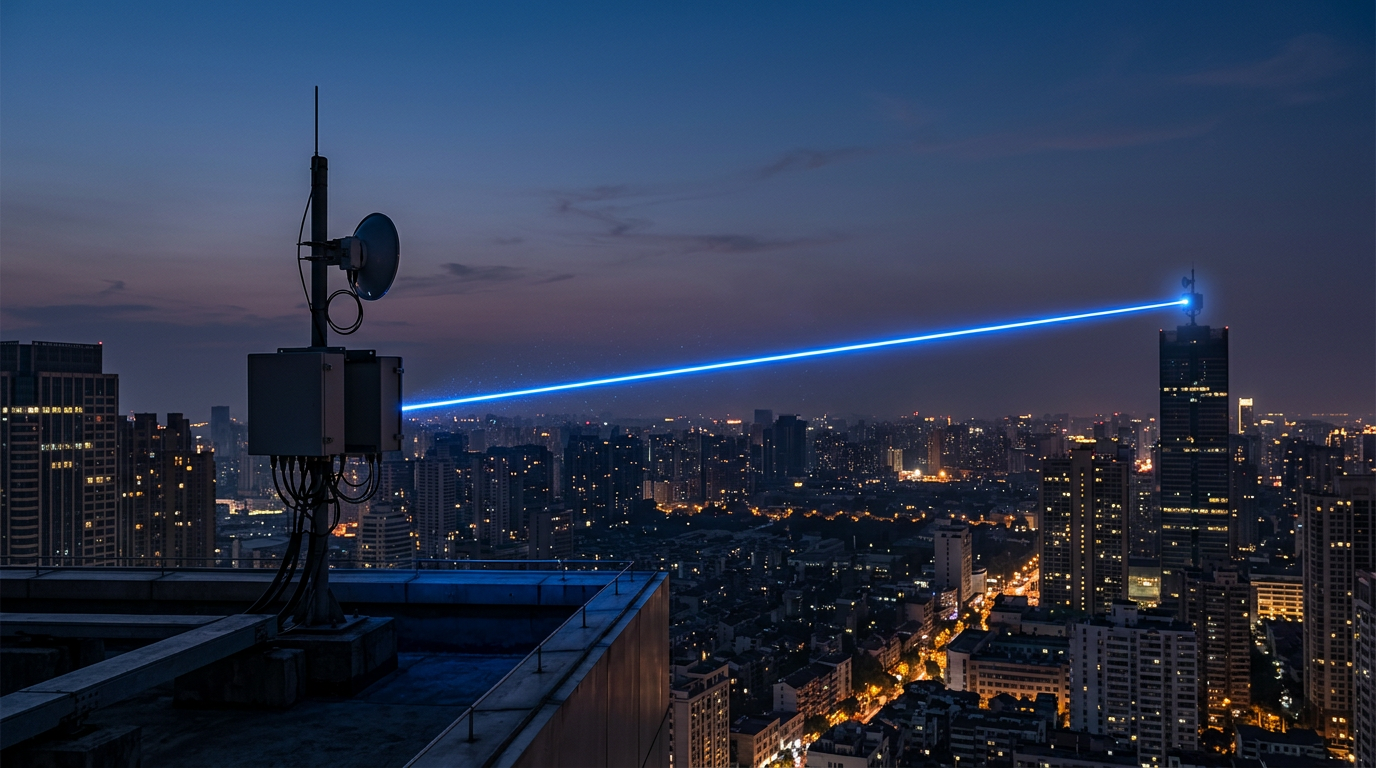
Free space optics equipment is the hardware that sends data on modulated laser beams through open air, vacuum, or water — no fibre cable, no radio spectrum licence, no physical channel between the two endpoints beyond the medium itself.
Free space optics (FSO) is a distinct technology category, not a variant of RF wireless or fibre optic communication: it uses optical frequencies rather than radio frequencies, and it propagates light through an unguided medium rather than through glass.
Every FSO system shares the same three-part architecture: a transmitter that generates, modulates, and collimates the optical beam; a free-space channel through which the beam propagates; and a receiver that collects the incoming light, converts it to an electrical signal, and demodulates the data.
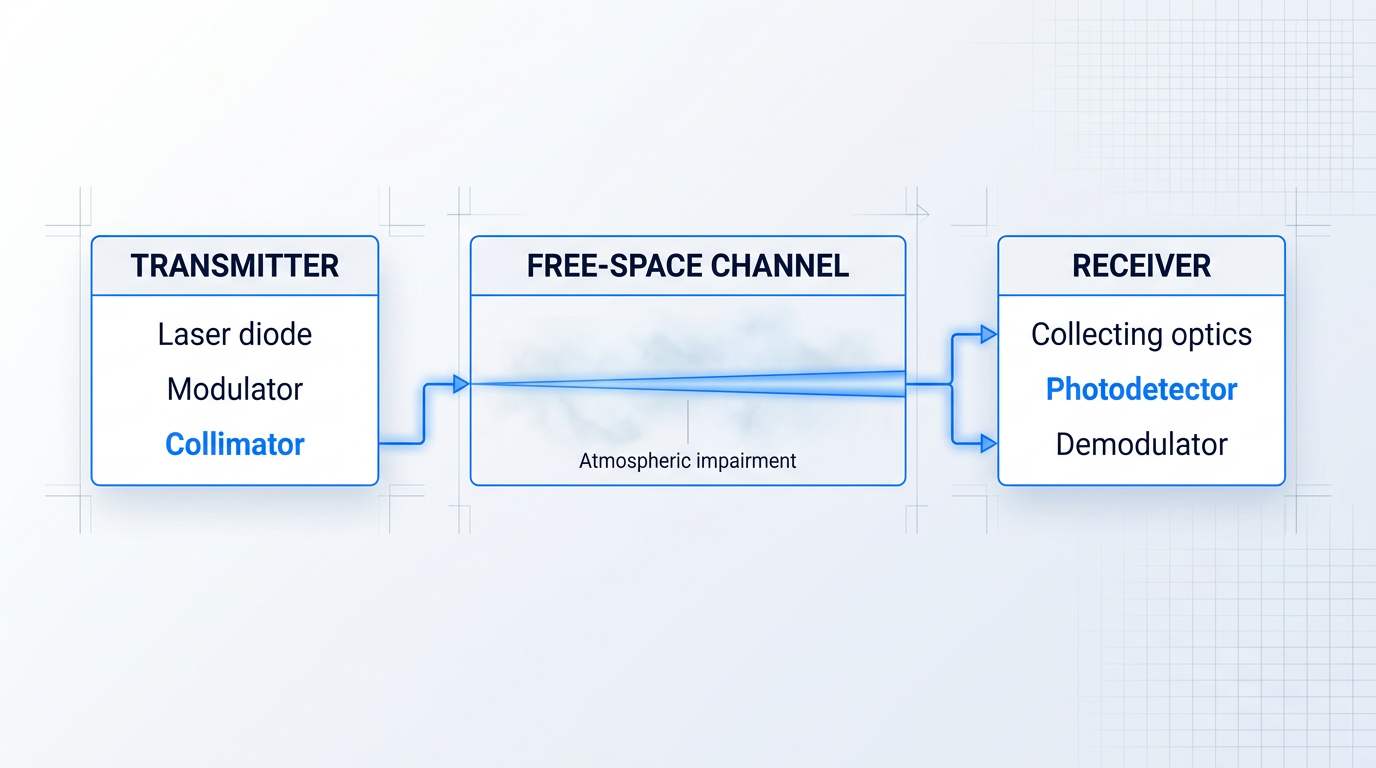
Laser light is the right carrier for this architecture because of three physical properties: coherence, monochromaticity, and directionality.
These properties work together: a coherent, single-wavelength beam can be tightly collimated to propagate over long distances with minimal divergence, enabling the high data rates and extended reach that make FSO commercially viable.
LEDs cannot substitute for laser diodes in high-performance FSO links — their output is both spectrally broad and inherently divergent, which prevents the tight beam collimation that long-distance optical transmission requires.
The performance envelope FSO can cover is substantial: data rates range from hundreds of Mbps at short terrestrial ranges up to 1.72 Tbps over distances exceeding 10 kilometres, with satellite-to-satellite applications extending reach to thousands of kilometres.
Commercial FSO systems operate principally in two near-infrared wavelength bands: around 850 nm and 1550 nm; wavelength selection carries significant engineering trade-offs that the guide addresses in a dedicated section.
Despite its performance range, FSO faces three principal engineering challenges that run through every system design decision.
- Atmospheric impairment: Absorption, scattering, and turbulence in the atmosphere attenuate and distort the optical beam, with fog representing the most severe impairment for terrestrial links.
- Line-of-sight dependency: FSO requires an unobstructed optical path between transmitter and receiver; physical obstacles break the link entirely, with no signal diffraction around barriers.
- Precision pointing and alignment: Narrow, collimated beams demand accurate, maintained alignment between link heads — building sway, thermal expansion, and vibration all introduce pointing error.
Against RF wireless, FSO operates at optical frequencies that sit entirely outside the regulated radio spectrum, making it licence-free in most jurisdictions — removing the spectrum coordination costs and lead times that RF alternatives carry — while producing a far narrower beam that reduces interference and improves physical link security.
The trade-off versus RF is weather sensitivity: fog and aerosols attenuate optical beams far more severely than they affect radio frequencies, a constraint that shapes every terrestrial FSO link design.
Against fibre, FSO uses the same optical signals through a different medium: air instead of glass, which means no trenching, no civil works, and deployment measured in hours rather than weeks.
FSO is the only communication technology that combines fibre-class bandwidth with licence-free operation and infrastructure-free deployment — a combination no RF or fibre alternative can replicate in full.
With the architecture and fundamentals established, the logical next step is understanding what each component inside that transmitter-channel-receiver framework actually does — and how component choices determine the link's overall performance.
Core Components of an FSO System
A spec sheet for a single FSO component tells you almost nothing about whether a link will hold up under real conditions. What determines link reliability is how every component in the chain performs together — and the weakest element sets the ceiling for the entire system, regardless of how impressive the others look on paper.
Laser Diode Transmitters
Laser diodes are the dominant transmitter source in free space optics equipment because their core properties map directly onto what FSO links demand: the coherence and directionality of laser light make tight, low-divergence beam collimation possible, while monochromaticity — a single or very narrow wavelength output — enables efficient optical filtering at the receiver to reject background light.
Equally important for high-speed links, laser diodes can be modulated directly at frequencies up to several GHz by varying the drive current, delivering high data rates in a compact, power-efficient package.
That said, direct modulation carries a limitation: varying the drive current also causes chirp — a transient frequency spreading of the optical spectrum — which degrades signal fidelity at very high data rates and limits usable link distance.
External modulation addresses this by placing a separate electro-optic modulator, typically a Mach-Zehnder modulator, after the laser resonator. The laser runs at a constant drive current, preserving spectral purity, while the modulator encodes the data with low chirp and supports bandwidths reaching tens to hundreds of gigahertz — at the cost of added insertion loss and system complexity.
The practical trade-off is straightforward: direct modulation suits cost-sensitive or shorter-range links where chirp is manageable; external modulation is the right architecture when signal fidelity at high data rates is non-negotiable.
Signal Encoding Formats
How data is encoded onto the optical carrier is a system-level design decision with real consequences for receiver complexity, sensitivity, and link performance — not an implementation detail to resolve at the end.
- On-off keying (OOK): The simplest format: laser on for a 1-bit, off for a 0-bit. Widely used in commercial FSO systems for its implementation simplicity, though it does not exploit available bandwidth when SNR is high.
- Pulse position modulation (PPM): Encodes data in the time position of a pulse rather than its presence or absence. Power-efficient and favoured in photon-starved or deep-space FSO applications, but at the cost of reduced bandwidth efficiency.
- OFDM: Orthogonal frequency division multiplexing distributes data across multiple sub-carriers, improving spectral efficiency and providing some resilience to channel impairments, at significantly higher receiver complexity.
The choice of encoding format directly shapes what the receiver must do: OOK demands the least from the detector chain, PPM requires precise timing and benefits from photon-counting detectors, and OFDM demands sophisticated signal processing but can extract more throughput from a given link margin.
Collimating and Receiving Optics
A raw laser diode output is highly divergent — FWHM angles of up to 40° on the fast axis and around 10° on the slow axis are typical — which makes collimating optics essential rather than optional.
Aspheric lens assemblies or multi-element collimators reshape this divergent cone into a near-parallel beam, and the quality of that collimation directly determines beam divergence — a critical parameter because smaller divergence means less geometric spreading loss over distance, which translates directly into more power arriving at the receiver.
On the receiver side, a telescope or lens assembly — the receive aperture — collects the incoming beam and focuses it onto the photodetector's active area.
Aperture area matters on two counts: collected power scales proportionally with aperture area, improving the received signal level; and a larger aperture also provides aperture averaging of turbulence-induced intensity fluctuations, because it integrates across a wider spatial extent of the beam and partially smooths out the variation.
Aperture size is therefore a significant system design parameter — one that affects both the raw power budget and the link's tolerance to atmospheric conditions.
Photodetectors: PIN Diodes vs APDs
The photodetector converts the received optical signal back into an electrical one, and the choice between the two principal types has a measurable impact on whether a link closes under atmospheric stress.
| Parameter | PIN Photodiode | Avalanche Photodiode (APD) |
|---|---|---|
| Internal gain | None (gain = 1) | Avalanche multiplication; typical gain of tens to ~100 at optimal operating point |
| Receiver sensitivity advantage | Baseline reference | 5 to 10 dB better sensitivity than PIN at comparable bandwidth |
| Active area vs bandwidth | Larger active area (up to mm-scale) tolerates pointing error; higher capacitance limits bandwidth | Hundreds-of-microns active area; tighter pointing required but higher bandwidth achievable |
| Bias voltage and complexity | Low voltage; simple bias circuitry | High reverse bias required; temperature-dependent gain needs compensation circuitry |
| Cost | Lower | Higher |
| Typical FSO application fit | Short-range, cost-sensitive links with abundant received power | Long-range or high-margin links where sensitivity is the limiting factor |
Comparison of PIN photodiodes and avalanche photodiodes (APDs) on the parameters that matter most for FSO receiver design.
The sensitivity gap between the two detector types has direct operational consequences: for a given transmit power and link distance, an APD-based receiver can close a link that a PIN photodiode-based receiver cannot — particularly under fog or turbulence conditions that reduce the received signal level.
There is also a genuine engineering trade-off within each detector type: a larger active area captures more of the focused beam and tolerates some degree of pointing error, but the higher junction capacitance that comes with it limits bandwidth — meaning that maximising pointing tolerance and maximising data rate pull in opposite directions.
Optical Amplifiers: EDFAs and SOAs
Optical amplifiers are not simply a way to add power — they are a system-level capability multiplier that extends range, improves atmospheric margin, and enables post-amplification receiver architectures that would otherwise be impossible.
Erbium-doped fibre amplifiers (EDFAs) are the mature, high-performance option for FSO systems operating at 1550 nm, providing typical small-signal gains of 20 to 40 dB — figures confirmed across IEEE TechNav and IEEE Spectrum documentation of the technology.
That gain can be applied as a power booster ahead of the transmit aperture, as a preamplifier before the photodetector, or as an in-line amplifier — each architecture serving a different system objective.
The 1550 nm specificity of EDFAs is not incidental: it is one of the primary reasons that wavelength dominates high-performance FSO system design, a connection that the next section explores in full.
Semiconductor optical amplifiers (SOAs) offer a compact, lower size-weight-and-power (SWaP) alternative — relevant for airborne, tactical, or CubeSat platforms where EDFA bulk is prohibitive — but they deliver lower saturation output power and generally lower gain than their fibre-based counterparts.
A high-power transmitter paired with a poorly specified receiver does not produce a reliable link. Excellent collimating optics paired with an undersized receive aperture loses the geometric advantage at the far end. A link that looks adequate on individual component specs can still fail under atmospheric stress if any one element in the chain is mismatched to the others — FSO performance is an emergent property of the full component set, not a sum of individual ratings.
The component choices surveyed here — detector type, amplifier architecture, collimation quality, aperture size — all interact with one variable that has not yet been examined in depth: wavelength.
Because EDFAs operate specifically at 1550 nm, because detector materials (InGaAs versus silicon) are wavelength-dependent, and because collimation quality is itself wavelength-influenced, component selection and wavelength selection are deeply intertwined — which is exactly what the next section unpacks.
Wavelength Choice and Trade-offs in FSO Systems
Ask a vendor why their FSO equipment operates at 1550 nm and you will almost certainly hear that it "penetrates fog better" and is "eye-safe." Both statements contain truth, but neither is the whole story — and the gaps matter when you are specifying a link. Wavelength selection is one of the most consequential decisions in FSO system design, and it is also one of the most frequently misrepresented.
Commercial free space optics equipment is principally built around two wavelength bands: the 780–850 nm and 980 nm near-infrared region, and the 1550 nm band. Both are in active, widespread use. Neither is universally superior. The right choice depends on link distance, required availability, cost envelope, and system architecture — and understanding why requires looking at each of the underlying engineering trade-offs in turn.
Why 1550 nm Dominates Commercial FSO
The structural advantage of 1550 nm begins with eye safety, and it is decisive. Wavelengths above approximately 1400 nm are absorbed by the cornea and lens before they can reach the retina, which is the photosensitive tissue where laser damage actually occurs. At 800 nm, by contrast, the anterior optics of the eye are highly transmissive and concentrate incoming light by roughly 100,000 times onto the retina — making even modest power levels potentially hazardous without any warning sensation.
Under IEC 60825-1 — the general laser product safety standard — this biological difference translates directly into a classification advantage. Within the Class 1 and Class 1M limits, 1550 nm systems may emit significantly higher transmit power than equivalent 850 nm systems. Multiple industry sources, including the NSMA Mecherle paper and CableFree's technical documentation, cite the permissible power advantage as approximately 50 times higher for 1550 nm relative to 780–850 nm systems. This is not a marginal benefit: it feeds directly into link margin and achievable range.
IEC 60825-12 applies these principles specifically to free space optical communication systems, setting out engineering controls and safety requirements for FSO deployments as a distinct product category. Wavelength and output power together set a system's safety class: 1550 nm allows more power than 850 nm within the Class 1/1M limits, while amplified watt-level transmitters are Class 4 laser products that need engineering controls and site safety measures — a classification that flows into every link budget calculation.
The second advantage of 1550 nm is atmospheric. This wavelength sits within a near-infrared transmission window characterised by low molecular absorption, and solar background radiation in the 1200–1600 nm spectral region is substantially lower than at shorter near-infrared wavelengths. Research from the Ioffe Institute quantifies the solar irradiance at 1550 nm as approximately five times weaker than at 800 nm, which reduces the receiver noise floor and improves signal-to-noise performance — particularly relevant for daytime operation.
Third, 1550 nm is the operating wavelength of erbium-doped fibre amplifiers (EDFAs). As covered in the previous section, EDFAs provide 20–40 dB of gain and represent the dominant high-gain amplification technology in telecoms. A 1550 nm FSO link can be boosted using commercially mature, cost-effective EDFA hardware — a system-level advantage confirmed by real-world deployments, including the Sydney 2000 Olympic Games FSO link documented in SPIE Volume 4214. Systems operating at 850 nm cannot exploit EDFA gain; they would require semiconductor optical amplifiers (SOAs), which offer lower gain and different noise characteristics.
For defence and tactical applications, 1550 nm also offers a beam collimation characteristic that supports low probability of intercept and detection (LPI/LPD) requirements — a point explored further in the section on defence use cases.
In dense fog (visibility below approximately 500 m), attenuation is approximately wavelength-independent — 785 nm, 850 nm, and 1550 nm are all attenuated equally, as confirmed by Kim et al. in SPIE Volume 4214 through full Mie scattering calculations. The 1550 nm advantage in fog comes from its higher permissible transmit power under IEC 60825-1, not from a lower scattering coefficient at that wavelength. When a vendor claims 1550 nm "penetrates fog better," the engineering basis is the eye-safety power headroom, not a wavelength-dependent scattering property.
When 850/980 nm Systems Are the Right Choice
The case for 850/980 nm is real and should not be dismissed as a legacy position. Silicon photodetectors, which operate efficiently in the 850/980 nm range, offer higher sensitivity than the InGaAs detectors required at 1550 nm. As discussed in the previous section's treatment of PIN and APD receivers, silicon APDs can achieve multiplication gains of 100 to 1000 — substantially higher than the 30–40 achievable with InGaAs APDs — which translates into meaningful receiver sensitivity at shorter wavelengths.
For short-to-medium range links — typically up to around 1–2 km under good visibility conditions — where optical amplification is not required and the eye-safety power advantage is less critical to closing the link budget, 850/980 nm systems can deliver competitive real-world link margin at meaningfully lower component cost. Silicon detectors are cheaper and more widely available than InGaAs; 850 nm laser sources benefit from decades of volume production driven by CD and datacom applications.
It is also worth noting that aperture geometry interacts with eye-safety classification in ways that complicate simple wavelength comparisons. A large-aperture 980 nm system can, under certain conditions, present a lower actual hazard than a small-aperture 1550 nm system — a nuance that CableFree's technical documentation flags as frequently overlooked in 1550 nm advocacy. The IEC classification framework accounts for aperture and measurement distance, not just wavelength.
The practical guidance is straightforward: if you are specifying a campus or enterprise link at 500–1000 m without a requirement for EDFA amplification or carrier-grade availability in dense fog, 850/980 nm may be the more cost-effective and technically sufficient choice. If you need maximum range, the highest atmospheric margin, or integration with fibre-optic network infrastructure operating in the C-band, 1550 nm is the rational selection.
Wavelength is one of several parameters that directly shape the link budget — it affects permissible transmit power, atmospheric attenuation characteristics, and receiver sensitivity all at once. The next section explains how these parameters combine with geometric loss and system margins to determine whether a given FSO link is viable at a specified range and availability target.
FSO link budget: how system parameters determine viability
A vendor datasheet can tell you the transmit power, the receiver sensitivity, and the claimed range — but none of those figures, read in isolation, tells you whether a proposed FSO link will actually hold up at 500 metres in coastal fog, or at 2 km across an urban rooftop on a clear summer day. The answer to that question comes from link budget analysis: the engineering discipline that combines every gain and loss in the signal chain into a single margin figure.
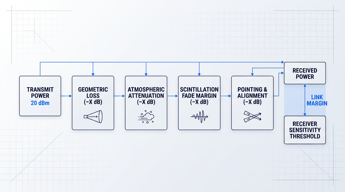
Link margin is the power available at the receiver above the minimum sensitivity threshold. It is the quantity that must remain positive under worst-case atmospheric conditions for the link to maintain its target bit error rate (BER) — the measure of transmission quality that determines whether data arrives intact.
Everything in the link budget either contributes to that margin or erodes it. The parameters that matter most are consistent across all FSO systems, regardless of manufacturer or application.
- Transmit power: The optical output of the transmitter, including any EDFA or SOA amplification, bounded above by eye-safety regulations (IEC 60825-1 and IEC 60825-12).
- Geometric loss: Power lost to beam spreading over distance, determined by beam divergence angle and receiver aperture size. Present even in perfectly clear air.
- Atmospheric attenuation: Variable absorption and scattering from fog, haze, rain, snow, and aerosols. The dominant driver of link unavailability in terrestrial FSO.
- Scintillation loss: Rapid intensity fluctuations from atmospheric turbulence. Statistically characterised and accounted for via a fade margin allowance.
- Receiver sensitivity: The minimum detectable power for the target BER at the operating data rate. Defines the floor below which the link fails.
- Pointing and alignment loss: Power lost from beam misalignment between transmitter and receiver. A fixed system loss term addressed in detail in the tracking section.
Transmit power and the eye-safety ceiling
Transmit power is the most direct lever for improving link margin: more optical power at the transmitter means more power available at the receiver after losses. EDFAs, as established in the components section, can add 20–40 dB of optical gain at 1550 nm, making amplification a practical route to higher effective transmit power.
That lever has a safety dimension. IEC 60825-1 and IEC 60825-12 classify transmitters by wavelength and emitted power: 1550 nm allows more power than 850 nm within the Class 1/1M limits, while amplified watt-level transmitters are Class 4 laser products that need engineering controls and site safety measures, as covered in the wavelength selection section. Transmit power, in practice, is a constrained optimisation: maximise within the safety class and controls the deployment can support.
Geometric loss: the unavoidable baseline
Even in a vacuum with no atmosphere at all, a laser beam diverges as it propagates. This geometric loss is a fundamental physical consequence of diffraction, not an atmospheric effect, and it scales with range.
The two parameters that govern it are beam divergence angle and receiver aperture diameter. A tighter beam — achieved through better collimating optics — spreads less over a given distance, so more power falls within the receiver aperture. A larger aperture collects a greater fraction of the diverging beam. Both reduce geometric loss; both have practical engineering limits.
Geometric loss is the baseline term in the link budget. Every other loss term is added on top of it, which is why geometric loss sets a hard minimum margin requirement even before atmospheric conditions are considered.
Atmospheric attenuation: the variable loss term
Atmospheric attenuation is where the link budget becomes probabilistic. Unlike geometric loss, which is fixed for a given range and aperture, atmospheric attenuation changes with weather: fog, haze, rain, snow, and aerosol loading all absorb and scatter the optical beam to varying degrees.
The physical model underpinning this is the Beer-Lambert law, which describes how intensity decays exponentially with path length through an attenuating medium. The extinction coefficient in that model varies across several orders of magnitude depending on atmospheric conditions — dense fog can produce losses exceeding 100 dB/km, while clear air contributes only a few tenths of a dB/km.
ITU-R P.1814 provides the standards framework for translating visibility measurements into attenuation estimates, giving engineers a principled basis for modelling atmospheric loss from meteorological data at a proposed deployment site.
Because atmospheric attenuation is statistically variable, it cannot be treated as a single fixed number in the link budget. It must be characterised as a distribution, and the margin calculation must account for the tail of that distribution — the conditions under which the link is most likely to fail.
Scintillation: a distinct statistical impairment
Atmospheric turbulence introduces a separate and statistically distinct loss mechanism: scintillation. Temperature and pressure gradients in the atmosphere create refractive index variations along the beam path, causing rapid intensity fluctuations at the receiver.
The strength of this turbulence is characterised by the refractive index structure parameter Cn², which varies with altitude, time of day, and surface heating. Scintillation fades can reach 20–30 dB in magnitude and occur over timescales of tens of milliseconds — far faster than the slow onset of fog attenuation.
This temporal character is what makes scintillation a distinct budget term. Fog attenuation is a sustained impairment that persists for minutes to hours; scintillation fades are brief but can be severe. The link budget accounts for scintillation through a fade margin allowance — a reserved power buffer sized to the statistical depth of expected fades at the deployment location — rather than as a fixed loss value.
Receiver sensitivity: the margin floor
Receiver sensitivity defines the minimum optical power at which the detector can recover the signal at the target BER. Everything above that threshold is margin; anything below it is a link failure.
As established in the components section, the choice between PIN and APD photodetectors has a direct bearing here. APDs offer approximately 6 dB better sensitivity than PIN detectors, which translates directly into 6 dB of additional link margin — a meaningful contribution when atmospheric conditions are eating into the budget.
Sensitivity also degrades with data rate. Higher-throughput links require wider receiver bandwidth, which admits more noise and raises the sensitivity threshold. A 10 Gbit/s link needs more received power to achieve the same BER as a 1 Gbit/s link over the same path — which means higher-data-rate systems inherently require more margin to compensate.
Translating availability targets into margin requirements
The practical question link budget analysis answers is not just "what is the margin?" but "is this margin sufficient to meet the availability target at this location?" A 99.9% availability requirement means the link must remain operational during all but 8.76 hours per year — which translates directly into a required margin above the median atmospheric loss that is large enough to cover the tail of the attenuation distribution.
ITU-R P.1817 provides propagation prediction methods that, combined with local visibility statistics, allow engineers to estimate what margin is needed to achieve a given availability figure at a specific site. A coastal location subject to frequent advection fog demands far more margin than an arid inland site with similar link geometry.
This is the bridge between the abstract link budget and the real-world deployment question. Availability is not a property of the hardware alone — it is an emergent result of how the hardware's margin interacts with the statistical character of the atmosphere at the installation point.
A link budget forces evaluation of the complete signal chain. Improving one parameter raises potential margin, but the weakest element in the chain sets the effective ceiling — regardless of how well every other parameter is specified. A high-power transmitter cannot compensate for an inadequate receiver; a sensitive receiver cannot compensate for poorly collimated optics. This is why link budget thinking is the right lens for evaluating FSO equipment claims: individual specs are meaningless without the system context.
Atmospheric attenuation and scintillation are the two loss terms that dominate link budget uncertainty in terrestrial FSO — their magnitudes, physical mechanisms, and the engineering approaches used to account for them are examined in depth in the next section.
EDFA Technology Built for Free Space Optical Links
Link margin is only as good as the amplifier behind it. Our EDF-UL-10 is purpose-built for FSOC applications, delivering high average output power with on-demand modulation to keep your link stable under real atmospheric conditions.

Atmospheric Interference: Impairments and Engineering Mitigations
The atmosphere is not a passive medium for FSO links — it is an active, variable channel that adds attenuation on top of the geometric and system losses already captured in the link budget. How much margin an FSO system needs, and which design choices provide it, depends entirely on which atmospheric impairments dominate at a given location. Each impairment type has a distinct physical mechanism, a characteristic severity range, and a corresponding set of engineering responses. Understanding them at this level of precision is what separates a link that holds up under real conditions from one that looks adequate on a datasheet.
Fog and Mie Scattering
Fog is the dominant availability-limiting impairment for terrestrial FSO equipment in temperate climates. The physical mechanism is Mie scattering: water droplets with diameters comparable to the optical wavelength (roughly 1–100 µm) scatter the beam energy strongly out of the propagation path, producing attenuation that scales inversely with visibility.
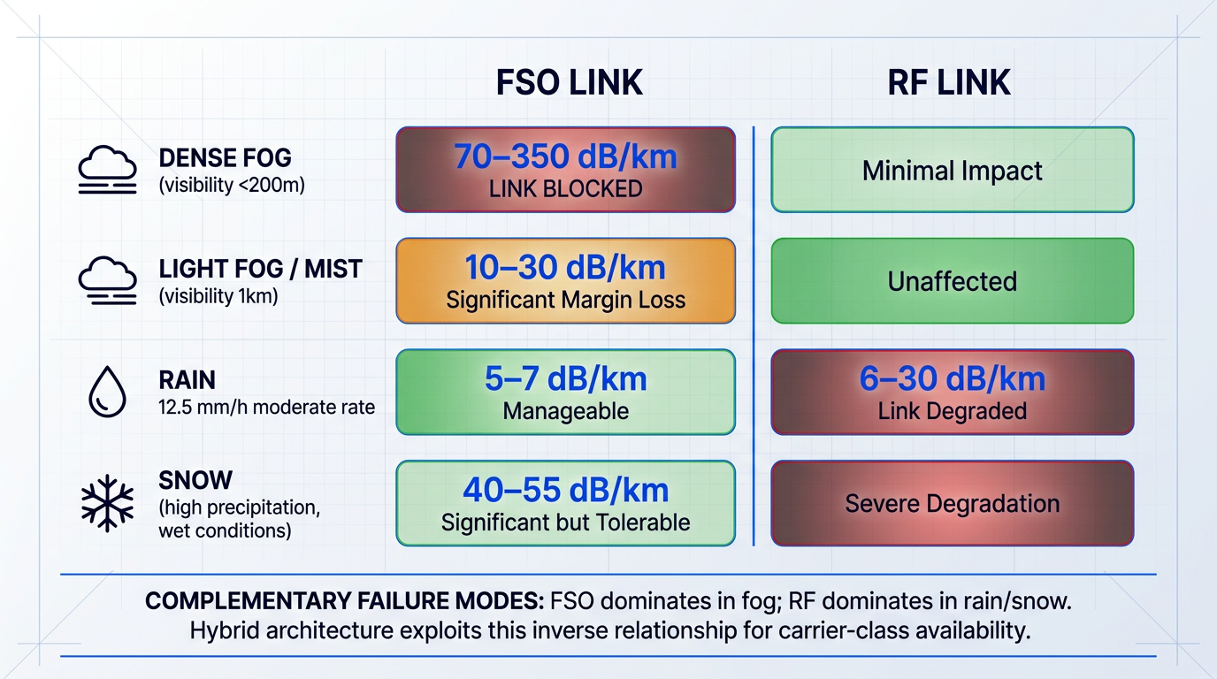
The severity range is wide. Light fog (visibility around 1 km) produces attenuation of approximately 10–20 dB/km — manageable with adequate link margin. Dense fog (visibility below 200 m) can reach 70–350 dB/km, which is sufficient to extinguish any link beyond a few hundred metres regardless of transmit power.
A nuance worth correcting here connects directly to the wavelength discussion established earlier in this guide. Below approximately 500 m visibility, the Kim model's particle size distribution coefficient q drops to zero, making attenuation effectively wavelength-independent across the near-IR range used by FSO systems. The practical implication: the fog-penetration advantage often cited for 1550 nm equipment comes from the higher permissible transmit power that the 1550 nm eye-safety classification allows — not from any reduction in scattering at that wavelength.
In link budget terms, fog attenuation flows directly into the Aatmo term. A 500 m link in moderate fog (28.9 dB/km per the ITU-R P.1817 international visibility code) consumes roughly 14.5 dB of margin — a significant fraction of a typical 20–40 dB system margin. Dense fog at 200 m visibility (75 dB/km) would consume 37.5 dB over the same path, exceeding most practical margins entirely.
Rain and Snow Attenuation
Rain droplets are much larger than the optical wavelength, placing them in the geometric scattering regime where attenuation is wavelength-independent. This size difference is also why rain attenuates FSO links far less severely than fog: typical rain attenuation ranges from 6–30 dB/km depending on rainfall rate, with a moderate rain event of 12.5 mm/h producing roughly 5–7 dB/km.
Snow attenuation can reach approximately 40–55 dB/km at high precipitation rates, depending on snow type and wavelength. Wet snow at low altitude is generally more attenuating than dry snow. Both rain and snow represent significant but usually manageable impairments — the critical point is that they are also the conditions under which RF links suffer their greatest degradation, which has direct implications for the hybrid FSO/RF mitigation strategy discussed below.
Haze and Aerosol Scattering
Haze (visibility roughly 2–10 km) produces moderate attenuation of approximately 3–20 dB/km through Mie scattering from aerosol particles. This is generally manageable with adequate link margin and does not typically drive link unavailability on its own.
The standard engineering tools for estimating haze attenuation from visibility data are the Kim and Kruse visibility models, which relate the atmospheric attenuation coefficient to measured visibility through a wavelength-dependent power law. These models feed directly into the Aatmo term in the link budget and are codified in ITU-R P.1814-1. Designers working in haze-prone environments should obtain local visibility statistics from airport databases or meteorological stations to build a statistically grounded margin allocation.
Atmospheric Turbulence and Scintillation
Scintillation is physically distinct from scattering: it arises from temperature-driven refractive-index fluctuations that create cells of varying optical density across the beam path. These cells cause beam wander, beam spreading, and rapid intensity fluctuations at the receiver — without removing energy from the atmosphere in the way fog does.
Turbulence strength is characterised by the refractive index structure parameter Cn², which at optical wavelengths typically ranges from 10⁻¹⁶ m⁻²/³ (weak turbulence, night-time or overcast conditions) to 10⁻¹² m⁻²/³ (strong turbulence, midday over sun-heated surfaces). ITU-R P.1814-1 documents fade depths of 0.39 dB at 1.55 µm for low turbulence (Cn² = 10⁻¹⁶) rising to 12.25 dB for high turbulence (Cn² = 10⁻¹³) over a 1 km path — and field measurements confirm fades can reach 20–30 dB under strong turbulence conditions.
The temporal structure of scintillation fades matters as much as their depth. Fades last on the order of tens of milliseconds, with intensity fluctuations at frequencies spanning 0.01–200 Hz per ITU-R P.1817. This millisecond-scale duration is short enough to be addressed by error coding with interleaving, but long enough to cause burst errors that overwhelm uncoded receivers. Crucially, scintillation cannot be addressed simply by adding transmit power — a deeper fade requires the same margin increase regardless of the absolute power level, making spatial and coding approaches the primary engineering responses.
The table below compares all four impairment types across the dimensions most relevant to link budget planning and mitigation selection.
| Impairment | Typical Attenuation Range | Physical Mechanism | Temporal Character | Primary Mitigation |
|---|---|---|---|---|
| Dense fog | 70–350 dB/km | Mie scattering (droplets ~wavelength size) | Continuous during fog events; duration hours | Link margin; hybrid FSO/RF fallback |
| Light fog / mist | 10–30 dB/km | Mie scattering | Continuous during event | Link margin design |
| Rain | 6–30 dB/km (rate-dependent) | Geometric scattering (droplets >> wavelength) | Intermittent; variable duration | Link margin; hybrid FSO/RF |
| Snow | Up to ~40–55 dB/km | Geometric scattering | Intermittent; variable duration | Link margin; hybrid FSO/RF |
| Haze / aerosols | 3–20 dB/km | Mie scattering (aerosol particles) | Persistent; slowly varying | Link margin; Kim/Kruse model for planning |
| Scintillation (turbulence) | Fades 20–30 dB peak; 0.4–16 dB at 1 km | Refractive-index fluctuations (Cn²) | Rapid; fades last tens of milliseconds | FEC with interleaving; spatial diversity; aperture averaging |
Comparison of FSO atmospheric impairment types across attenuation severity, physical mechanism, temporal characteristics, and primary mitigation approach — enabling engineers to match design choices to impairment profiles.
The most important pattern in this table is the contrast between fog and scintillation. Fog produces the highest absolute attenuation and is the primary driver of link unavailability in temperate climates — but it is a slow, continuous impairment that responds to raw link margin. Scintillation produces moderate fade depths but operates on millisecond timescales, meaning it cannot be absorbed by margin alone; it requires approaches that exploit the temporal or spatial structure of the fading.
Rain and snow occupy a middle position: severe enough to require margin allocation, but rarely the worst-case condition for FSO, and critically, they are the conditions under which RF links are most impaired — a complementarity that forms the engineering basis for hybrid FSO/RF design.
Mitigation Approaches
Link margin design is the foundational mitigation tool. The system is engineered with enough power above the receiver sensitivity threshold to tolerate worst-case atmospheric attenuation for the target availability level. Every other mitigation in this section either increases the available margin or reduces the margin required to meet a given availability target.
Spatial diversity and aperture averaging are two related but distinct spatial approaches, both particularly effective against turbulence-induced fading. In spatial diversity, multiple spatially separated transmitters or receiver apertures collect light over partially decorrelated paths — reducing the probability that all paths are simultaneously in a deep fade. The apertures must be separated by at least the turbulence correlation length (typically a few centimetres to tens of centimetres for near-ground horizontal links) to achieve meaningful decorrelation.
Aperture averaging works differently: a single large receiver aperture integrates intensity fluctuations across its face, smoothing out the spatial intensity pattern produced by scintillation and reducing the effective scintillation index at the detector. Both approaches target turbulence-induced fading specifically — neither provides meaningful relief against fog, where the attenuation is spatially uniform across any practical aperture separation.
Forward error correction (FEC) coding effectively extends the link margin without increasing transmit power or aperture size. Reed-Solomon codes have demonstrated coding gains of up to 8 dB in FSO applications, and FEC coding gains in the 3–8 dB range are consistent with the broader FSO literature for RS and LDPC codes. This gain translates directly into additional margin against the Aatmo term in the link budget.
Interleaving is the critical companion to FEC for scintillation-dominated links. Scintillation fades lasting tens of milliseconds cause burst errors — consecutive erroneous bits that can overwhelm a single FEC codeword. Interleaving spreads these burst errors across multiple codewords before the FEC decoder sees them, converting a burst error pattern into a correctable random-error pattern. This combination of FEC with interleaving is specifically matched to the millisecond-scale fade duration characteristic of atmospheric turbulence.
The hybrid FSO/RF architecture pairs the FSO link with an RF backup that activates when FSO attenuation exceeds the available margin. The engineering logic depends on a specific and measurable property of the two technologies: their failure modes are complementary under the dominant weather impairments.
FSO and RF fail under different atmospheric conditions. Dense fog — the primary cause of FSO outages — has minimal effect on RF links. Heavy rain attenuates RF (particularly at microwave and millimetre-wave frequencies) but causes far less FSO attenuation than fog. Because the two technologies fail under different weather regimes, a hybrid system can achieve 99.999% availability at ranges where neither technology could reach that target operating alone. ITU-R P.1817 data from a Prague measurement campaign shows FSO-only availability of 99.7% and RF-only (58 GHz) availability of 99.999% on the same path, with a hybrid system reaching 99.9999%.
The hybrid approach is particularly relevant for carrier-class availability targets, where the FSO link alone cannot survive the worst-case fog conditions without impractically short link distances. The RF backup operates at lower data rates, but the fraction of time it is the active link is small — the high-bandwidth FSO path carries traffic the vast majority of the time.
Atmospheric impairment and pointing error are the two dominant sources of link margin consumption in terrestrial FSO — and while the engineering responses to atmospheric impairment are the focus here, precision beam alignment under real-world conditions introduces its own margin demands. That challenge is examined in detail in the next section on beam pointing, acquisition, and tracking.
Beam Pointing, Acquisition, and Tracking in FSO Systems
The same property that makes an FSO beam capable of carrying high-bandwidth data — its narrow beam divergence — is precisely what makes alignment an active, continuous engineering challenge rather than a one-time installation task.
Commercial FSO systems typically operate with divergence angles in the 1–5 mrad range; high-performance systems push well below 100 µrad. At these angles, even a small angular error translates directly into a large received-power loss, and for a Gaussian beam profile, the optimal pointing error sits at approximately one-third of the beamwidth — exceed that threshold and link margin erodes rapidly.
The perturbations that drive misalignment come from several distinct physical sources, each with its own frequency character and therefore its own demands on the correction system.
- Building sway: Thermal expansion and wind loading cause slow, chronic angular drift in rooftop-mounted terminals — a low-frequency perturbation that can persist for hours.
- Mechanical vibration: HVAC plant, traffic, and structural resonance introduce higher-frequency, smaller-amplitude motion that the tracking loop must reject continuously.
- Angle-of-arrival fluctuations: Atmospheric turbulence bends the arriving beam, producing apparent pointing error even when the terminal itself is physically stationary — a direct consequence of the turbulence effects covered in the previous section.
- Platform motion: Airborne, maritime, and vehicular platforms impose continuous, large-amplitude, high-frequency perturbations — the most demanding case for any PAT system.
Because these sources differ in frequency and amplitude, a well-designed PAT (pointing, acquisition, and tracking) system must have sufficient correction bandwidth to address all of them simultaneously — not just the slowest or largest.
The PAT architecture: acquisition to continuous tracking
Establishing and maintaining an FSO link follows three sequential phases, each of which must complete successfully before the next can begin.
- Coarse acquisition: The terminal broadcasts a wide-divergence beacon beam to scan the uncertainty volume where the counterpart terminal is expected, achieving rough alignment from a large initial pointing error.
- Fine acquisition: Using the detected beacon signal, the system narrows to a precise direction, transitioning from wide-angle search to narrow-angle precision before data transmission begins.
- Continuous tracking: A closed-loop control system maintains alignment throughout operation, correcting for all perturbation sources in real time to sustain the data link.
The sequential dependency is rigid: a link cannot enter fine acquisition without completing coarse acquisition, and continuous tracking must be active for the data link to be maintained.
Acquisition time — the combined duration of phases one and two — is a practical system parameter that matters most in tactical and mobile deployments, where links must be re-established quickly after interruption or platform manoeuvre.
Fast steering mirrors and quadrant detectors
The primary fine-pointing actuator in most FSO PAT systems is the fast steering mirror (FSM): a piezoelectrically driven tip/tilt mirror that deflects the beam with high speed and sub-microradian precision.
NIST-documented characterisation of commercial macro tip/tilt FSMs shows an angular range of ±2.5 mrad, a resolution of 0.05 µrad, and a resonant frequency in the range of approximately 3 kHz — a combination that enables correction of both vibration and turbulence-induced fluctuations within a single compact actuator.
It is this combination of high bandwidth, fine resolution, and compact form factor that makes FSMs the dominant fine-pointing actuator: no other commercially mature technology offers the same performance envelope within the size and power constraints of a typical FSO terminal.
The sensor that drives the FSM control loop is the quadrant photodetector — a four-element detector that measures beam position error by comparing the optical power incident on each of its four quadrants using monopulse arithmetic.
The difference signal between opposite quadrant pairs yields a two-axis error signal; the FSM is then commanded to null that error, recentring the beam on the detector. The elegance of this approach is that the same optical signal carrying the data link also carries the position information used to maintain alignment — no separate tracking beacon is required in many implementations.
MEMS-based steering mirrors offer a compact, low-SWaP alternative to conventional FSMs, trading some performance headroom for dramatically reduced size and power consumption. SPIE proceedings document MEMS FSM designs that fit within a 1U CubeSat form factor (10 cm × 10 cm × 10 cm) alongside a 1 mm quad detector, enabling active acquisition and tracking in platforms where a conventional FSM assembly would be entirely impractical.
The tracking bandwidth required of a PAT system scales directly with beam narrowness: a 1 mrad beam demands far tighter continuous correction than a 5 mrad beam. This is why fixed-pointing systems — which accept wider beams — can operate reliably without any tracking hardware at all, and why that is often the right engineering choice rather than a compromise.
Fixed-pointing versus active-tracking
Fixed-pointing systems broaden the transmitted beam — typically above 5 mrad — so that building movement and installation imprecision remain within the beam footprint without any corrective hardware. Practical experience confirms that systems with beamwidths above 5 mrad can operate reliably and remain unattended for years after initial alignment, making them well-suited to stable rooftop mounts and shorter link distances.
Active-tracking systems use narrower beams to achieve lower geometric loss and better spatial selectivity, but require FSM, quadrant detector, and control loop hardware to sustain that performance. They are the necessary choice for long-range links, high data rates, tall-building mounts subject to significant sway, and — critically — any mobile platform where perturbations are continuous and large-amplitude.
The choice between the two approaches depends on link range, target data rate, mounting stability, platform type, and budget. Neither is universally superior: a fixed-pointing system is frequently the correct engineering decision for commercial building-to-building deployments, while active tracking becomes unavoidable as range increases or platform dynamics intensify.
Alignment requirement is one of the characteristics that most clearly distinguishes FSO from RF wireless — and it is one of several axes on which the next section compares FSO against RF and fibre alternatives across the full range of deployment contexts.
FSO vs RF Wireless vs Fibre: Performance Compared
Most FSO-versus-fibre comparisons on the web reduce three genuinely different technologies to a single table of ticks and crosses — and in doing so, they answer the wrong question. The useful question is not which technology is best, but which is best suited to a specific deployment context, budget horizon, and availability target.
FSO, RF wireless, and fibre optic cable are complementary tools, not competitors in a hierarchy. Each dominates under conditions where the others are constrained — and the engineering case for choosing one over another depends on the performance axes that actually matter to the deployment: bandwidth, spectrum regulation, weather sensitivity, deployment speed, physical security, propagation latency, and cost structure.
| Performance Axis | FSO | RF Wireless (E-band) | Fibre Optic |
|---|---|---|---|
| Bandwidth capacity | Hundreds of Mbps to multiple Tbps demonstrated. DLR demonstrated 1.72 Tbps in 2016 and 13.16 Tbps in 2017 in ground-station trials under turbulent-channel conditions. LEO CubeSat downlinks have achieved 100 Mbps. | Up to 10–25 Gbps commercially. Ericsson/Deutsche Telekom demonstrated 40 Gbps over 1.4 km and 100 Gbps over 1.5 km in pre-commercial E-band research trials. | Effectively unlimited — capacity constrained by terminal electronics and WDM channel count, not the fibre medium itself. |
| Spectrum licensing | Licence-free worldwide. Optical wavelengths above 300 GHz fall outside regulated RF spectrum — no fees, no coordination lead time, no geographic restrictions. | Requires licensing. In the UK, Ofcom charges £50/link/year for E-band (71–86 GHz). In the US, FCC charges a $105 application fee plus $25 annual regulatory fee per Part 101 microwave licence. | No spectrum licence required, but rights-of-way, wayleaves, and civil works permits are needed — a different but equally real regulatory burden. |
| Primary weather impairment | Fog and heavy snow. Dense fog reaches 30–350 dB/km attenuation. FSO links over ~140 m typically cannot achieve 99.999% availability without RF backup in temperate climates. | Rain fade. At E-band frequencies in European climate zones (ITU-R Zone K, ~42 mm/hr), rain attenuation reaches 16–17 dB/km. Adaptive modulation mitigates fade; well-designed links maintain 99.999% availability. | Unaffected by weather once installed. Physical cable is immune to atmospheric conditions. |
| Deployment speed | Hours to days. No trenching, no spectrum coordination, no civil works. A service provider can be revenue-generating while a fibre competitor is still seeking street-dig permits. | Days to weeks. No trenching, but spectrum registration and site clearance add lead time. A trained team can install an E-band link in under a day once site approvals are granted. | Weeks to months. Requires civil engineering, trenching, and municipal permitting. Urban fibre deployment is particularly slow and expensive. |
| Physical link security | Narrow collimated beam is inherently difficult to intercept without detection. Beam does not propagate omnidirectionally and cannot penetrate opaque obstacles. Genuine advantage for defence and sensitive enterprise — not an absolute guarantee. | RF signals propagate omnidirectionally and can be intercepted at a distance without physical access to the link path. Higher interception and jamming risk than FSO. | Physically enclosed medium — interception requires physical access to the cable. High inherent security once installed. |
| Propagation latency | Light propagates through air at ~3×10⁸ m/s. Research on hollow-core fibre — which also transmits through air — quantifies the refractive-index advantage as ~30%, or ~1.54 µs/km, versus conventional silica fibre. FSO shares this same physics. | Also propagates through air at the speed of light — same per-unit-distance latency as FSO. The Ericsson/Deutsche Telekom E-band trial demonstrated round-trip latency under 100 µs over 1.4 km. | Light in silica fibre travels at ~5 µs/km versus ~3.33 µs/km in air — an inherent latency penalty of roughly 1.5–1.6 µs/km relative to air-propagating links. |
| Cost structure | Low upfront cost: terminal equipment only, no trenching. IEEE Spectrum case study showed FSO at under one-fifth the capital cost of comparable fibre. Lightwave Online data shows FSO carrier networks pay back in ~14 months vs ~4 years for fibre. | No trenching cost. Ongoing spectrum licence fees (£50/link/year in UK E-band). At higher frequencies, equipment costs are comparable to FSO terminals. | High upfront civil works cost — urban fibre can run to hundreds of dollars per metre of trench. Very low ongoing cost once installed; lowest total cost over a long horizon in greenfield environments. |
Engineering comparison of FSO, RF wireless (E-band), and fibre across the seven performance axes that determine technology selection in real deployments, with specific figures from research sources.
Several patterns emerge across this comparison. FSO and E-band RF occupy similar bandwidth territory and similar deployment speed profiles, but diverge sharply on weather sensitivity and spectrum regulation — FSO requires no licensing but is vulnerable to fog, while E-band requires registration but is resilient to the fog events that ground FSO links.
The latency advantage of air-propagating links over conventional fibre is grounded in the refractive index of silica glass: light travels roughly 50% faster in air than in glass, translating to a latency saving of approximately 30% per kilometre. Research on hollow-core fibre — which transmits through an air-filled core and shares the same physics as FSO and RF propagation — quantifies this as approximately 1.54 µs/km saved relative to conventional fibre. This advantage is most relevant at the link level; end-to-end network latency is dominated by routing hops and processing, not per-kilometre propagation.
The physical security comparison also warrants precision. FSO's narrow beam provides a genuine, engineering-grounded interception barrier — the beam does not propagate beyond its intended path, and physical obstruction breaks the link rather than deflecting it. IEEE peer-reviewed sources confirm this advantage is real for defence and sensitive enterprise applications, while noting it is not absolute: a determined adversary with access to the beam periphery can still attempt interception.
When FSO is the right technology choice
The comparison is most useful when read through the lens of deployment constraints rather than abstract performance rankings. FSO is the optimal choice when several specific conditions apply simultaneously.
- No fibre rights-of-way: When fibre trenching is blocked by urban permitting, cost, or physical barriers, FSO delivers comparable bandwidth without civil works.
- Spectrum licensing is undesirable: FSO's licence-free status eliminates coordination lead time and ongoing fees — critical for rapid deployment or geographically constrained sites.
- Rapid deployment is required: Disaster recovery, temporary event links, and bridging connections while permanent fibre is installed can all be live within hours using FSO.
- Physical link security matters: Defence, government, and sensitive enterprise links benefit from FSO's narrow-beam interception resistance in ways RF cannot match.
- High bandwidth without fibre infrastructure: Where Gbps-class throughput is needed and fibre is unavailable, FSO is the only wireless option approaching fibre-grade capacity without spectrum licensing.
FSO is a poor fit when line-of-sight cannot be guaranteed, when the deployment site experiences persistent dense fog, or when the link must achieve carrier-class 99.999% availability at distances beyond a few hundred metres without a backup path.
FSO fails under fog and heavy snow; E-band RF fails under heavy rain. Five years of hourly weather data from Seattle showed no simultaneous occurrence of dense fog and the rain rates that impair a microwave backup link — the two failure modes are meteorologically complementary. A hybrid FSO/RF system exploits this to achieve 99.999% availability at distances an FSO-only system cannot reach, with the high-bandwidth FSO path active the vast majority of the time.
This complementarity reframes FSO's weather sensitivity from a limitation into a design parameter: rather than treating fog vulnerability as a reason to reject FSO, engineers can pair it with a lower-bandwidth RF backup that activates only when the optical path is impaired — conditions that do not simultaneously affect microwave links operating below the rain-fade threshold.
With the technology comparison established, the practical question becomes how these trade-offs play out across specific deployment contexts — telecom backhaul, enterprise campus links, satellite ground stations, and defence applications each weight these axes differently, and the right equipment specification follows from that weighting.
Ready to Evaluate FSO for Your Deployment?
Whether you have a specific link scenario in mind or want to explore what free space optical communications technology can do, we can help you move from evaluation to decision.
FSO Deployment: Use Cases, Availability, and Evaluation
Understanding how FSO works is only half the job. The harder question — the one that determines whether a deployment succeeds or fails — is which context you are operating in, what availability that context demands, and what those demands require from the equipment. The answers form a single chain of reasoning, and the rest of this section walks through it.
Primary Deployment Contexts
Four deployment contexts account for the vast majority of free space optics equipment installations, each with distinct data rate demands, availability targets, and engineering constraints. The right specification decisions in each context follow directly from understanding what that context actually requires.
Telecom Backhaul
Telecom backhaul is the highest-volume commercial FSO application, operating at Gbps-range data rates with the appeal of rapid deployment and no spectrum licensing — both significant advantages over fibre in dense urban environments where right-of-way is constrained.
The defining tension in this context is between commercial pressure for carrier-class SLAs — 99.999% availability, roughly five minutes of downtime per year — and the atmospheric reality that fog dominates availability loss in temperate climates.
At ranges beyond a few hundred metres in temperate or coastal environments, FSO-only links cannot reliably reach five-nines availability; hybrid FSO/RF backup is the practical engineering solution, with the RF link activating when fog drives the optical path below threshold.
Enterprise Campus Connectivity
Enterprise campus links operate over distances of roughly 100 m to 2 km and benefit from FSO's protocol transparency — the link carries Gigabit Ethernet, SONET, or other protocols without modification, making integration with existing infrastructure straightforward.
A target of 99.9% availability — approximately 8.76 hours of downtime per year — is typically sufficient for enterprise applications, which significantly relaxes link margin and redundancy requirements compared to carrier-class deployments.
At shorter campus ranges where building sway is manageable, fixed-pointing systems with a wider beam divergence are common; active tracking is reserved for longer spans or high-wind urban environments.
Satellite Ground Station Connectivity
Satellite ground station FSO represents the frontier of the discipline — the most demanding engineering context in the field, where every component choice is pushed to its limit.
On the uplink path, adaptive optics systems pre-compensate for atmospheric turbulence before the beam enters the atmosphere; on the downlink, large-aperture telescope assemblies maximise the received power collected from the satellite.
Cloud cover is effectively opaque to FSO, so ground station network diversity — multiple geographically separated stations — is the primary mitigation strategy, ensuring that cloud cover over one station does not interrupt the link entirely.
1550 nm is the preferred wavelength in this context: its compatibility with EDFA amplification is essential for building the power budget needed across the ground-to-satellite path, and SOA alternatives at the same wavelength are an emerging option for space-qualified amplification.
Defence and Tactical Communications
FSO's narrow beam geometry creates an inherent low probability of intercept and detection (LPI/LPD) advantage: very little energy is radiated outside the intended path, and no RF emissions are produced, making the link covert by design.
For man-portable and vehicle-mounted terminals, SWaP constraints — size, weight, and power — are critical; the NRL TALON programme demonstrated that FSO terminals can be built at an order of magnitude lower SWaP than earlier defence FSO attempts while achieving 100 Mbps at ranges up to 70 km.
Mobile platforms — ground vehicles, aircraft, ships — require robust tracking systems capable of maintaining alignment while both endpoints are in motion; this is the context where the PAT architectures covered earlier in this guide become most operationally critical.
1550 nm and SWIR wavelengths are preferred in defence applications for both eye-safety and sensor compatibility reasons, and the licence-free nature of the optical spectrum means FSO alleviates RF congestion on already-crowded tactical communications bands.
Availability Targets and Redundancy Architecture
The gap between 99.9% and 99.999% availability is not incremental — it is a fundamentally different system architecture requirement, and the equipment specification follows directly from which side of that gap the deployment must sit on.
99.9% availability permits 8.76 hours of downtime per year. 99.999% permits 5.26 minutes. Closing that gap requires fundamentally different link margins, redundancy architectures, and — in most temperate climates at ranges beyond a few hundred metres — hybrid FSO/RF infrastructure. It cannot be achieved by simply increasing transmit power.
Availability targets must be grounded in local visibility statistics, not vendor range claims. A system that achieves 99.9% availability in an arid climate may achieve only 95% on the same link geometry in a temperate coastal city — the atmospheric environment, not the hardware spec sheet, sets the ceiling.
The modelling frameworks established in earlier sections of this guide — ITU-R P.1817 for propagation data and ITU-R P.1814 for prediction methods — are the standard tools for translating local climate data into link availability predictions; buyers should require vendors to use these frameworks, not generic maximum-range figures.
For carrier-class availability, analysis of link budgets against worst-case visibility conditions shows that FSO-only links are limited to roughly 140 m in the most severe temperate fog environments (350 dB/km attenuation) — a figure that rises in more benign climates but remains a hard constraint without RF backup.
Beyond that threshold, hybrid FSO/RF is not a hedge — it is the practical engineering conclusion, supported by multi-year measurement campaigns showing that FSO and RF fail under different conditions (fog vs heavy rain), making the combination significantly more effective than either technology alone.
Four redundancy approaches address different failure modes, and specifying the right architecture requires understanding which failure mode each one actually targets.
- Spatial diversity: Multiple spatially separated FSO paths reduce the probability that all paths are simultaneously impaired by the same turbulence cell or fog patch.
- Redundant transmitters: Multiple transmitters within a single head protect against hardware failure — not atmospheric impairment. This does not extend link availability in fog.
- ATPC: Automatic Transmit Power Control dynamically increases transmit power as conditions worsen, extending link connectivity before the margin is fully consumed.
- Hybrid RF backup: FSO carries traffic under normal conditions; an RF link activates when FSO drops below threshold. FSO and RF fail under different conditions, making this combination effective.
These approaches are not mutually exclusive. Carrier-class deployments in challenging climates typically combine ATPC for real-time margin management, spatial diversity to reduce simultaneous impairment probability, and a hybrid RF backup for the residual outage events that neither of the first two can absorb.
Equipment Evaluation Parameters
When assessing any FSO system — evaluating a vendor proposal or scoping a new deployment — the following parameters determine whether the system can actually meet the availability target in the intended environment.
- Link margin at range: The fundamental viability question: does the system have sufficient margin to meet the availability target under local atmospheric conditions at the deployment distance?
- Wavelength and IEC safety class: 1550 nm allows higher transmit power than 850 nm within the IEC 60825-1 Class 1/1M limits, because the eye is opaque to wavelengths above 1400 nm; amplified watt-level transmitters are Class 4 and need engineering controls and site safety measures.
- Transmit power and amplification: Raw transmit power combined with any EDFA or SOA amplification determines the total power budget available before geometric and atmospheric losses are applied.
- Receiver type and sensitivity: PIN vs APD: APDs provide approximately 5–10 dB sensitivity advantage, relevant for longer links or higher availability targets where every decibel of margin matters.
- Beam divergence and aperture size: Smaller divergence reduces geometric loss; larger receive aperture collects more power and provides aperture averaging of scintillation — both improve effective link margin.
- Tracking capability and acquisition time: What tracking technology is used, its angular range, and how quickly it reacquires after interruption — critical for mobile platforms and high-wind urban deployments.
- Environmental and standards compliance: IP66/NEMA-4 ingress protection; operating range typically −40°C to +60°C for carrier-grade equipment; IEC 60825-12 laser safety; ITU-T G.641 interface specifications.
- Vendor availability predictions: Require predictions based on local visibility statistics for the deployment site. Generic 'range up to X km' claims are meaningless without the atmospheric context behind them.
The evaluation parameters above are not independent: link margin is the output that all other parameters feed into, and it must be validated against local visibility data — not the vendor's headline specification.
With these use cases, availability targets, redundancy approaches, and evaluation criteria fully articulated, the final step is to consolidate them into a coherent decision framework — which is precisely what the conclusion to this guide addresses.
Conclusion
Specifying FSO equipment: the decisions that matter
FSO performance is a system-level outcome — what link margin, wavelength, tracking capability, and redundancy architecture produce together, under the atmospheric conditions specific to your deployment, is what determines whether a link holds at the availability your application demands.
The evaluation criteria this guide has established are the tools for identifying the contexts where FSO is genuinely the right choice: where rapid deployment matters, where civil works are impractical, or where a physically secure, licence-free optical path is the right fit for the problem.
Frequently asked questions about free space optics equipment
Practical answers to common questions about FSO deployment, performance limits, laser safety standards, and how FSO compares to related technologies.
Commercial FSO systems are typically specified for ranges up to 4–7 km in clear air, but that figure is a vendor spec measured under ideal conditions. The operationally relevant number is the availability-constrained range — and in most temperate climates, achieving 99.9% availability without hybrid RF backup limits practical deployments to roughly 500 m–2 km. Range is not a fixed property of the hardware. It is a function of link margin and local atmospheric conditions, particularly fog frequency. A system rated for 4 km in clear air may only deliver 99.9% availability at 500 m in a fog-prone climate, because dense fog can drive attenuation to 200–350 dB/km, consuming the entire link budget. For carrier-class 99.999% availability, FSO-only links are generally limited to well under 500 m in most locations. The practical solution for extending high-availability range is a hybrid FSO/RF architecture: the RF backup operates during fog events (when FSO fails), while FSO carries the load during rain (when RF is more susceptible). This complementary failure behaviour is why hybrid systems can achieve 99.999% availability at distances an FSO-only system cannot.
Yes — FSO can transmit through glass windows, and this is a recognised deployment advantage for customers who cannot access a rooftop. However, two practical caveats apply. First, window angle: the pane should be close to perpendicular to the beam, with a slight offset of a few degrees to prevent back-reflections from re-entering the transmitter optics. Second, and more significantly, window coatings matter. Uncoated clear glass typically attenuates an FSO signal by around 15% across a standard double-pane unit (roughly 4% loss per surface from reflection). Tinted or coated glass — including IR-reflective and low-emissivity (low-e) coatings common in modern commercial and energy-efficient buildings — can cause substantially higher attenuation, potentially enough to degrade availability or break the link entirely. Before specifying a through-window installation, verify the window's optical transmission at the operating wavelength (typically 1550 nm). Measuring actual attenuation rather than relying on manufacturer coating specifications is the recommended approach for high-availability deployments.
Fog is the dominant atmospheric impairment for terrestrial FSO links. Dense fog can cause attenuation of 70–350 dB/km — sufficient to break most links entirely, regardless of transmit power or aperture size. The mechanism is Mie scattering: fog droplets (typically 1–20 µm in diameter) are comparable in size to near-infrared optical wavelengths, so they scatter the beam very efficiently. Unlike rain, which is characterised by much larger droplets, fog scattering is nearly wavelength-independent across the 850–1550 nm range used by commercial FSO equipment. Two mitigations are available. The first is link margin design — higher transmit power, larger receive aperture, and optical amplification all increase the margin available to absorb fog attenuation, extending the range at which a given availability target can be met. The second, and more effective for carrier-class requirements, is a hybrid FSO/RF backup. Because fog attenuates optical links while having minimal effect on RF signals, and because heavy rain attenuates RF while having less effect on FSO, the two technologies fail under different conditions. A hybrid system that switches to RF during fog events can achieve 99.999% availability at link distances that FSO alone cannot sustain. Atmospheric attenuation modelling for FSO link planning is governed by ITU-R P.1814.
FSO has several inherent physical-layer security properties that make it more resistant to interception than RF wireless. The beam divergence of a laser link is extremely narrow — an eavesdropper would need to physically intercept the beam path, which causes a detectable power drop at the intended receiver. FSO signals do not penetrate opaque obstacles such as walls and buildings, unlike RF signals which propagate through structures and can be detected at a distance. There are also no radio-frequency emissions to detect or direction-find. These characteristics — low probability of intercept and low probability of detection — make FSO a preferred technology in government, defence, and intelligence applications where the physical security of the communications link is a requirement. It is worth noting that FSO's physical-layer properties do not eliminate the need for encryption at the data layer. Standard encryption protocols can be layered on top of an FSO link for end-to-end security. The physical security advantage is the difficulty of covert interception without detection, not immunity to all attack vectors.
Two IEC standards govern laser safety for FSO equipment. IEC 60825-1 is the general laser product safety standard covering classification and requirements for laser products across all applications. IEC 60825-12 is the FSO-specific standard, providing requirements and guidance for the manufacture and safe use of laser products used for free space optical data transmission. Most commercial FSO systems operating at 1550 nm are classified as Class 1M under IEC 60825-1. Class 1M is considered eye-safe for normal unaided viewing — the hazard arises only if the beam is viewed through optical instruments such as binoculars or telescopes, which concentrate the beam onto the retina. The physical basis for this classification at 1550 nm is that this wavelength is absorbed by the cornea and lens before it can reach the retina, which is the tissue most vulnerable to laser damage. This absorption characteristic allows Class 1M systems at 1550 nm to operate at significantly higher power levels than equivalent systems at 850 nm — the permissible power is roughly 50 times greater. That higher permissible power level is one of the primary engineering reasons 1550 nm dominates commercial FSO: it translates directly into longer link range and greater atmospheric margin.
Commercial FSO systems typically support data rates from 100 Mbps to 10 Gbps, covering the range from Fast Ethernet to 10 Gigabit Ethernet — sufficient for most enterprise backhaul and campus connectivity applications. Research and demonstration programmes have achieved substantially higher rates. NASA's TBIRD programme demonstrated 200 Gbps laser communication downlinks from a small CubeSat in low Earth orbit, and field trials using advanced multiplexing techniques have shown multi-Tbps throughput over short distances. For terrestrial commercial deployments, the practical data rate ceiling is set by the link budget — available optical power, atmospheric margin, and receiver sensitivity — along with the component technology used. Higher data rates generally require more precise alignment and better receiver sensitivity. The technology itself does not impose a fundamental ceiling anywhere near current commercial rates; the constraints are engineering and economics rather than physics.
No. FSO does not require spectrum licensing. Optical wavelengths fall outside the regulated radio-frequency spectrum in virtually all jurisdictions, making FSO licence-free to operate. This is a commercially significant advantage over microwave and millimetre-wave wireless alternatives — E-band (70/80 GHz) links, for example, require spectrum licences that involve registration costs, coordination processes, and ongoing regulatory compliance. FSO can typically be deployed without any frequency coordination or spectrum approval. The absence of licensing also removes lead time: an FSO link can be commissioned as quickly as the equipment can be installed and aligned, rather than waiting on regulatory approval. One practical note: local planning permissions or building consents may still be required for mounting equipment on rooftops or building facades, but these are property and planning matters, not spectrum regulation. The licence-free status applies to the optical transmission itself.
FSO and Li-Fi are both optical wireless technologies, but they are designed for fundamentally different applications and do not compete with each other. Li-Fi uses modulated visible or near-infrared light — typically from LEDs — for indoor, room-scale wireless connectivity. It is a last-metre technology, analogous to Wi-Fi but using light instead of radio waves, with coverage limited to a single room or small area. FSO uses laser beams in the near-infrared (typically 1550 nm) for outdoor, point-to-point links between buildings or across longer distances. It is a backhaul or access technology, not a room-scale connectivity solution. The key distinctions: Li-Fi is LED-based, visible-light or near-IR, short-range (metres), and supports multiple users in a broadcast topology. FSO is laser-based, near-infrared, long-range (hundreds of metres to kilometres), and operates as a point-to-point link. Li-Fi addresses in-room connectivity; FSO addresses building-to-building or longer links. Neither is a substitute for the other — they occupy different positions in the network architecture.