


Introduction
If you've encountered the term optical communication terminal in a programme brief, a procurement document, or a research paper, you're probably looking for something more useful than a dictionary definition.
This page is written for engineers, procurement professionals, policy researchers, and technically curious readers who want a coherent mental model — not a specification sheet.
By the end, you'll understand what these devices are, what makes them genuinely difficult to build, and why governments and commercial operators are deploying them in earnest right now.
The demand for higher data rates from space has collided with the hard limits of RF spectrum, and that collision is reshaping how satellite communications are designed and procured.
TL;DR
Optical communication terminals are not emerging technology — the physics is well understood, the engineering challenges are clearly defined, and operational deployments are already in orbit.
What has changed is the urgency: RF spectrum constraints have made laser-based links a practical necessity, not a research curiosity, for anyone building or procuring high-throughput space communications today.
This article covers:

OCT definition, operating principles, and subsystem architecture
Inter-satellite links and space-to-space optical operation
Space-to-ground links and optical ground station roles
Pointing, acquisition, and tracking (PAT) challenges
Atmospheric effects on optical downlinks and uplinks
Link budget fundamentals and design trade-offs
What Is an Optical Communication Terminal?
Most spacecraft carry a radio — an antenna that broadcasts signals across the electromagnetic spectrum to ground stations or relay satellites. An optical communication terminal does something fundamentally different: it encodes data onto a laser beam and transmits that beam through free space, whether through the vacuum of orbit or the Earth's atmosphere, to a receiving terminal on another spacecraft or on the ground.
The critical distinction is that an OCT is a complete transceiver system, not simply a laser or a telescope in isolation — it integrates the optics, the light source, the detector, and the precision pointing hardware needed to establish and hold a link across thousands of kilometres.
How OCTs Differ from RF Hardware
Conventional spacecraft RF systems operate within IEEE-designated radio bands of roughly 300 MHz to 40 GHz, transmitting via antennas that radiate broadly — the signal fans out and illuminates a wide area around the receiver.
Free-space optical links operate at near-infrared frequencies, with 1550 nm corresponding to approximately 193.5 THz — roughly 6,000 times the frequency of NASA's deep-space Ka-band downlink at 32 GHz.
That frequency advantage translates directly into bandwidth: optical frequencies can support data rates from gigabits to terabits per second, far exceeding the megabit-to-gigabit range typical of RF links.
There is also a regulatory difference with practical consequences: RF spectrum requires coordination and licensing through bodies such as the ITU, whereas optical frequencies are currently unregulated — there are no licensing requirements for laser communications.
The OCT beam is also far narrower than any RF beam, which gives it a low probability of intercept and makes it difficult to jam — but that same narrowness creates the central engineering challenge discussed below.
Why 1550 nm Is the Dominant Wavelength
OCT designers do not simply choose whatever wavelength is most convenient for physics — the selection of 1550 nm as the dominant wavelength for space optical communications reflects three converging advantages confirmed across NASA and JPL source material.
First, 1550 nm sits within an atmospheric transmission window of relatively low absorption, which is important for any link that must pass through the Earth's atmosphere on a space-to-ground path.
Second, 1550 nm carries a significant eye-safety advantage over the competing wavelength of 1064 nm: the maximum permissible exposure at 1550 nm is approximately 100 times higher than at 1064 nm, since the human eye reacts less efficiently to longer wavelengths — a practical consideration for ground operations where personnel may be near the receive aperture.
Third, and perhaps most decisively for commercial viability, the terrestrial fibre-optic telecommunications industry developed its component base — including erbium-doped fibre amplifiers (EDFAs) and associated photonic parts — at 1550 nm, because it is the optimum wavelength for low-loss transmission through silica fibre.
That industrial investment gives OCT designers access to a deep, cost-effective supply chain: NASA's TBIRD mission, which demonstrated a 200 Gbps downlink from low Earth orbit, used commercial off-the-shelf fibre telecom transceivers and an EDFA operating at 1550 nm.
The Free-Space Optical Transmission Mechanism
In a free-space optical link, data is modulated onto a laser carrier wave, and the modulated beam propagates as a narrow, coherent column of light through open space with no medium to guide or confine it.
At the receiving end, an aperture collects the arriving light and a detector demodulates it to recover the data stream — a signal chain conceptually similar to fibre-optic communications, except that free space replaces the waveguide.
The absence of a guiding medium means there are no medium losses accumulating along the propagation path. It also means the beam must arrive precisely where the receiver is positioned, with no tolerance for drift.
The Four Core Subsystems of an OCT
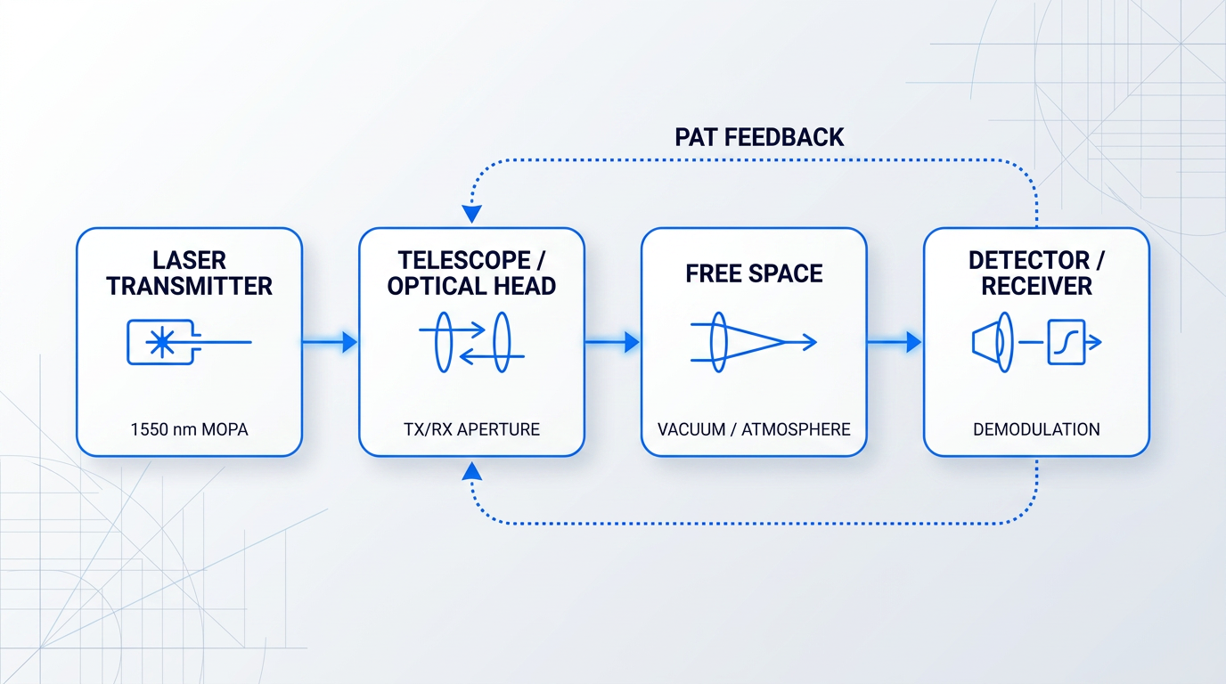
Every optical communication terminal, regardless of mission or manufacturer, is built around four core subsystems that together perform the complete transmit-and-receive function.
- Laser transmitter: Generates and modulates the optical carrier signal. Many space OCTs use a fibre-based master oscillator power amplifier (MOPA) configuration at 1550 nm.
- Telescope / optical head: Acts as both the transmit aperture — collimating and directing the outgoing beam — and the receive aperture, collecting incoming light. Aperture size is a primary design lever.
- Detector / receiver: Collects and demodulates the received optical signal to recover data. Sensitivity matters greatly given the extremely low power levels arriving from long distances.
- Pointing, acquisition, and tracking (PAT): Establishes and maintains precise alignment between the transmit beam and the distant receiver. The most demanding engineering challenge in the system.
The flight transceiver's optical train typically accommodates transmit, receive, acquisition, tracking, and calibration channels — all routed through a single front aperture and telescope, as documented in the JPL DESCANSO Monograph on deep-space lasercom.
The PAT subsystem is not a refinement added for performance — it is a prerequisite for any link to exist at all, since without it the transmit beam cannot reliably find and hold the receiver.
The Narrow-Beam Paradox
The OCT's narrow beam is simultaneously its greatest advantage and its defining engineering challenge — a paradox that runs through every aspect of the technology.
On the advantage side: a narrow beam delivers concentrated power to the receiver, limits the geographic footprint where the signal can be intercepted, and enables the enormous bandwidth that makes optical links attractive in the first place.
On the challenge side: OCT beams diverge on the order of microradians, so even a tiny pointing error — a fraction of a degree — causes the beam to miss the receiver entirely, as NASA's optical communications overview explicitly notes.
A 1550 nm optical link from a 10 cm aperture produces a beam spot roughly 6 km wide at lunar distance — compared to 6,400 km for a Ka-band RF system with a 75 cm antenna. That concentration is the source of the data-rate advantage, and the reason pointing accuracy is non-negotiable.
This is the intuition that makes the PAT subsystem comprehensible: the narrower the beam, the higher the gain — and the less margin there is for error in maintaining alignment between two moving terminals separated by thousands of kilometres.
OCTs serve three distinct link architectures: inter-satellite links (ISLs, connecting two spacecraft in orbit), space-to-ground downlinks, and ground-to-space uplinks — each presenting its own engineering environment and constraints, covered in the sections that follow.
With this architecture established, the natural starting point is the simplest operating environment for an OCT: linking two spacecraft in the vacuum of space, where there is no atmosphere between the terminals.
Step 1
Inter-satellite links: OCTs in space-to-space operation
Key Insights
ISLs operate in vacuum — no atmosphere.
Microradian pointing precision is the core challenge.
EDRS achieves 1.8 Gbps over 45,000 km.
SWaP constraints drive ISL terminal miniaturisation.
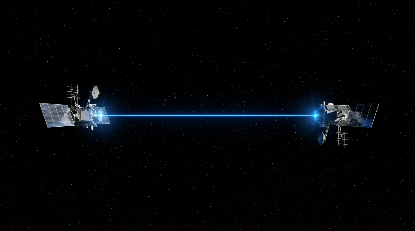
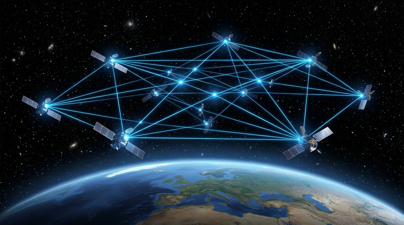
An inter-satellite link (ISL) is a laser link formed directly between two spacecraft, either within the same orbital plane (intra-plane) or across orbital planes (cross-plane).
The architectural significance of ISLs is that data can travel between satellites without routing through a ground station at all, enabling a mesh relay network that maintains coverage continuity and reduces end-to-end latency.
The clean-channel advantage
The defining physical characteristic of an ISL is the complete absence of atmosphere in the signal path — no weather, no turbulence, no cloud blockage, no scintillation.
Because the channel is governed purely by free-space propagation and pointing precision, ISL performance is highly predictable and stable in a way that space-to-ground links, which must contend with the atmospheric layer, are not.
Free-space path loss: aperture and power as design levers
The dominant loss mechanism in an ISL is free-space path loss — the geometric spreading of the laser beam as it propagates over distance.
A larger transmit aperture produces a narrower beam divergence, which concentrates power at the receiver across long distances; transmit power sets the energy available to overcome that spreading loss.
Aperture diameter and transmit power are therefore the primary design levers for an ISL terminal — a trade-off that becomes especially consequential when SWaP budgets are tight.
LEO satellites travel at approximately 7 km/s. Maintaining microradian-level beam alignment between two spacecraft in continuous relative motion — with a transmit beam narrow enough that any misalignment represents a significant fraction of the beam width — is the central engineering demand that ISL terminals must solve.
The pointing challenge is compounded by the fact that both ends of the link are moving simultaneously, so the terminal must continuously predict and compensate for relative angular motion in real time.
Demonstrated performance in operational systems
Operational ISL programmes have validated the technology at commercially and militarily significant data rates and distances.
| System | Terminal | Data Rate | Link Distance |
|---|---|---|---|
| EDRS (European Data Relay System) | Tesat-Spacecom LCT | Up to 1.8 Gbps | Up to 45,000 km (LEO-to-GEO) |
| SDA Proliferated Warfighter Space Architecture | SDA OCT Standard-compliant terminals (e.g. Mynaric Condor Mk3) | Up to 2.5 Gbps | Greater than 6,500 km |
Comparing the two most cited operational ISL benchmarks — EDRS and SDA — across data rate and link distance makes the performance envelope concrete and scannable without burying the figures in prose.
EDRS has operated commercially since 2016, logging tens of thousands of successful optical links between Copernicus Sentinel satellites in LEO and GEO relay nodes — making it the most mature operational ISL benchmark available.
Where ISLs are being deployed
Three use cases are driving ISL adoption at scale today.
- Constellation mesh networks: The SDA Proliferated Warfighter Space Architecture connects hundreds of LEO satellites via optical crosslinks, forming a high-speed mesh backbone for tactical data delivery without dependence on ground relay infrastructure.
- LEO-to-GEO data relay: The EDRS model uses GEO relay satellites to collect data from low-orbiting Earth observation satellites via ISL and forward it to ground in near-real time, dramatically reducing the contact-time constraint imposed by LEO ground station geometry.
- Military resilient communications: ISLs reduce dependence on fixed ground infrastructure, which is a strategic resilience advantage: a mesh of optically-connected satellites can route around ground station outages or denial.
Across all three use cases, the terminals must fit within the host spacecraft's mass, volume, and power budget — constraints that are far tighter on commercial LEO satellites than on heritage government or research platforms.
SWaP (size, weight, and power) constraints are the primary driver of miniaturisation in commercial ISL terminal design, distinguishing today's compact constellation terminals from the larger, power-hungry terminals developed for early government demonstration missions.
Step 5
Space-to-ground links: bringing data from orbit to Earth

Key Insights
Uplinks traverse the full atmosphere; downlinks only partly.
The ground station actively shapes link performance.
Site diversity is required for reliable availability.
A space-to-ground optical link is a bidirectional architecture: the OCT aboard the spacecraft transmits a downlink beam through the atmosphere to a ground receiver, while the optical ground station (OGS) transmits an uplink beam — and a pointing beacon — back toward the spacecraft.
The geometry differs markedly from the ISL environment covered in the previous step. A downlink beam travels through vacuum for the overwhelming majority of its path, encountering the atmosphere only in the final tens of kilometres before reaching the ground.
Downlinks traverse the atmosphere only at the end of their path. Uplinks are subject to atmospheric effects from the moment they leave the ground — across the full propagation to the spacecraft. The two directions of the same link face fundamentally different impairment profiles.
The OGS is not a passive receive dish — it is a co-equal engineering system whose design directly determines whether the link closes.
- Receive aperture: Collects the downlink beam and feeds it to the detector; aperture size sets the received power budget.
- Adaptive optics: Partially corrects wavefront distortion introduced by atmospheric turbulence on the downlink, improving coupling efficiency into single-mode fibres.
- Uplink transmission: Generates and amplifies the laser beam sent back to the spacecraft for data uplink in bidirectional configurations.
- Beacon generation: Transmits the pointing beacon the spacecraft terminal uses as its acquisition and tracking reference for PAT.
The quality of the uplink beacon matters directly to the spacecraft's pointing system: a weak or poorly conditioned beacon degrades the terminal's ability to lock onto and track the ground station — a topic the following section on pointing, acquisition, and tracking covers in full.
Demonstrated mission results confirm that space-to-ground optical links are well past the experimental stage. NASA's Lunar Laser Communication Demonstration (LLCD) achieved 622 Mbps on the downlink and 20 Mbps on the uplink from lunar orbit, and NASA's TBIRD mission demonstrated 200 Gbps from LEO.
OGS sites are selected to minimise atmospheric interference: high-altitude, low-latitude, dry locations reduce cloud frequency and water-vapour absorption. Even a well-sited station has finite availability, which is why site diversity — operating a network of geographically dispersed OGS sites — is a network-level requirement for reliable service.
Ground-segment uplink amplifiers must deliver sufficient power and beam quality to support both beacon and data functions simultaneously, and they must remain compatible with an evolving standards landscape — SDA and CCSDS waveform requirements are still being refined, and fixed-function hardware carries real programme risk as specifications change.
Amplifiers designed with this in mind — such as our solution, Woodrow Scientific's EDFA for free-space optical communications — address this directly. WSL's amplifier nests the tracking beacon and uplink data in a single beam, with the beacon tone riding low in amplitude and data modulated above it, removing the need for separate beacon and data transmitters.
The amplifier is configured to the client's ground station across both hardware (band, output power, emitter count, cooling) and software. WSL's Modulation-on-Demand layer makes the waveform, modulation index, and standard — CCSDS or SDA — selectable in software at full power, without hardware changes.
WSL designs, builds, qualifies, and supports the amplifier entirely in-house on patented technology, with fibre-amplifier expertise rooted in Southampton's Optoelectronics Research Centre. Many suppliers in this space are resellers or importers rather than manufacturers, which limits their ability to configure deeply or provide direct engineering support — a meaningful distinction when integrating into a programme with evolving requirements.
The amplifier is CE and UKCA certified.
Step 6
Pointing, Acquisition, and Tracking: The Defining Engineering Challenge

Key Insights
PAT has three phases: acquisition, tracking, pointing.
Deep-space pointing requires sub-microradian accuracy.
Coarse gimbal plus fine FSM spans full range.
Beacon-assisted vs beaconless: a real engineering trade-off.
Pointing, acquisition, and tracking (PAT) is the complete process by which an optical communication terminal finds its counterpart, locks onto it, and keeps the laser link open for the duration of a contact pass. It is not a single operation — it is three distinct phases that run in sequence to establish the link, then two of them run simultaneously and continuously to maintain it.
- Acquisition: The terminal does not yet know the counterpart's exact angular position. It scans a region of uncertainty — the field of uncertainty — using a wide-angle beacon or search pattern until it detects the counterpart's signal. Acquisition time grows nonlinearly with the size of that uncertainty region, which is why precise pre-contact attitude knowledge matters so much.
- Tracking: Once the counterpart is detected, the terminal locks its fine-pointing sensor onto the received beacon signal and maintains that lock continuously as both platforms move. The tracking loop drives the fast steering mirror to null the measured pointing error at high bandwidth.
- Pointing: The ongoing act of directing the transmit beam toward the distant receiver aperture with sufficient angular precision that the link budget's power delivery is maintained. Tracking and pointing run simultaneously during operation — tracking is the closed-loop control mechanism that achieves the pointing accuracy the link requires.
The reason PAT defines OCT architecture more than any other subsystem comes down to the scale of the problem. A typical transmit beamwidth is on the order of a few microradians — a beam that, at a range of 1,000 km, illuminates a spot perhaps a few metres across. Hitting that spot while both the transmitter and receiver are moving at orbital velocities is the engineering equivalent of threading a needle from the far end of a football pitch, in the dark, while both you and the needle are travelling at several kilometres per second.
According to JPL's Descanso Monograph Series, the required pointing accuracy for a typical lasercom terminal is a small fraction of a microradian — and the spacecraft platform's own attitude-control deadband and jitter can be several orders of magnitude larger than that requirement. The pointing system must suppress those disturbances down to the sub-microradian level continuously, not just at link establishment.
For deep-space missions, the demands are even more severe. Analysis from JPL's IPN Progress Report series shows that a beaconless star-tracker-based pointing system can achieve pointing knowledge on the order of 150 nanoradians (single axis, 1-sigma) — and that this figure sits comfortably below the typical deep-space optical communications requirement of roughly 200 to 300 nanoradians. At distances of multiple astronomical units, the beam has diverged to the point where the angular size of the receiving aperture is extraordinarily small, and there is no practical way to close a beacon-tracking loop given one-way light travel times that can exceed the contact window.
Two-stage architecture: coarse gimbal and fine mirror
No single actuator can span the full dynamic range that PAT requires — from gross angular uncertainty at acquisition (potentially several milliradians) down to sub-microradian residual error during tracking. The standard solution is a two-stage architecture where each stage handles a different portion of the frequency and amplitude spectrum.
- Coarse pointing assembly: A two-axis gimbal mechanically rotates the optical head toward the counterpart terminal, establishing the approximate line of sight. The spacecraft's attitude control system (reaction wheels, thrusters) supports this stage by keeping the body pointed within the gimbal's range. This stage handles large angular offsets and slow, low-frequency drift — it is not fast enough to reject vibration-induced jitter.
- Fine pointing: fast steering mirror: A fast steering mirror (FSM) inside the optical path compensates for residual jitter, attitude deadband, and high-frequency disturbances that the coarse stage cannot reject. FSMs used in lasercom terminals operate at bandwidths from hundreds of hertz up to around 2 kHz — fast enough to suppress the tonal vibrations produced by reaction wheels and other onboard mechanisms. The LAWS programme demonstrated that FSM-based control can hold short-term jitter to approximately 0.3 microradians RMS against realistic spacecraft disturbance environments.
The two stages are engineered to complement each other's bandwidth and stroke: the gimbal covers large angles slowly, the FSM covers tiny angles quickly. Together they achieve what neither could alone.
Beacon-assisted tracking versus beaconless pointing
The most common way to close the fine-pointing control loop is beacon-assisted tracking. As established in the previous section, the ground station transmits an uplink beacon laser toward the spacecraft. The OCT's fine-pointing sensor detects this beacon and uses it as an angular reference, driving the FSM to null the measured offset. The quality of the beacon matters: a weak or poorly collimated uplink signal is harder to acquire and track, and atmospheric disturbances on the uplink path add a further complication on top of platform jitter.
Beaconless pointing takes the opposite approach. Instead of relying on an uplink reference, the terminal uses onboard star trackers, gyroscopes, and inertial angle sensors — combined through a filtering algorithm — to compute its pointing direction directly from attitude knowledge. JPL's analysis shows that combining a star tracker (covering the low-frequency band below roughly 10 Hz), gyros (covering up to about 50 Hz), and high-bandwidth angle sensors (above 50 Hz) can achieve pointing knowledge of approximately 150 nanoradians, single axis, with a single star tracker and realistic hardware parameters.
The engineering trade is genuine. Beaconless pointing removes the need for a powerful uplink beacon, simplifying the ground segment significantly — but it shifts the complexity onto the spacecraft's attitude determination system. For deep-space missions where the round-trip light travel time makes real-time closed-loop beacon tracking physically impossible, beaconless pointing is not just an option but a necessity.
Platform jitter: the primary disturbance source
Even after the coarse stage has established the approximate line of sight, the spacecraft platform continuously injects high-frequency angular disturbances into the optical path. The dominant sources are reaction wheels, which produce tonal vibrations at their spin frequencies and harmonics due to mass imbalance and bearing imperfections; solar array drive mechanisms; and structural resonances excited by these sources.
Rejecting these disturbances is a systems engineering problem, not just a controls problem. It requires characterising the disturbance spectrum early in the design process, designing the FSM control loop with sufficient bandwidth to suppress the dominant tones, and where possible using structural isolation to reduce the energy that reaches the optical bench. The pointing loss that residual jitter produces feeds directly into the link budget — a point the next section will quantify.
NASA's Deep Space Optical Communications (DSOC) system, flying aboard the Psyche spacecraft, demonstrated 8.33 Mbps downlink at a range of 2.68 AU — close to the maximum Mars-Earth distance — and has operated at ranges up to 3.3 AU. This result confirms that the sub-microradian pointing control described throughout this section is achievable in practice, not merely in analysis, even at the most demanding deep-space ranges.
Step 7
Atmospheric effects on space-to-ground optical links
Key Insights
Uplinks traverse the full turbulent atmosphere immediately.
Cloud blockage needs network diversity, not hardware fixes.
DLR study: 8 sites achieved 99.971% link availability.
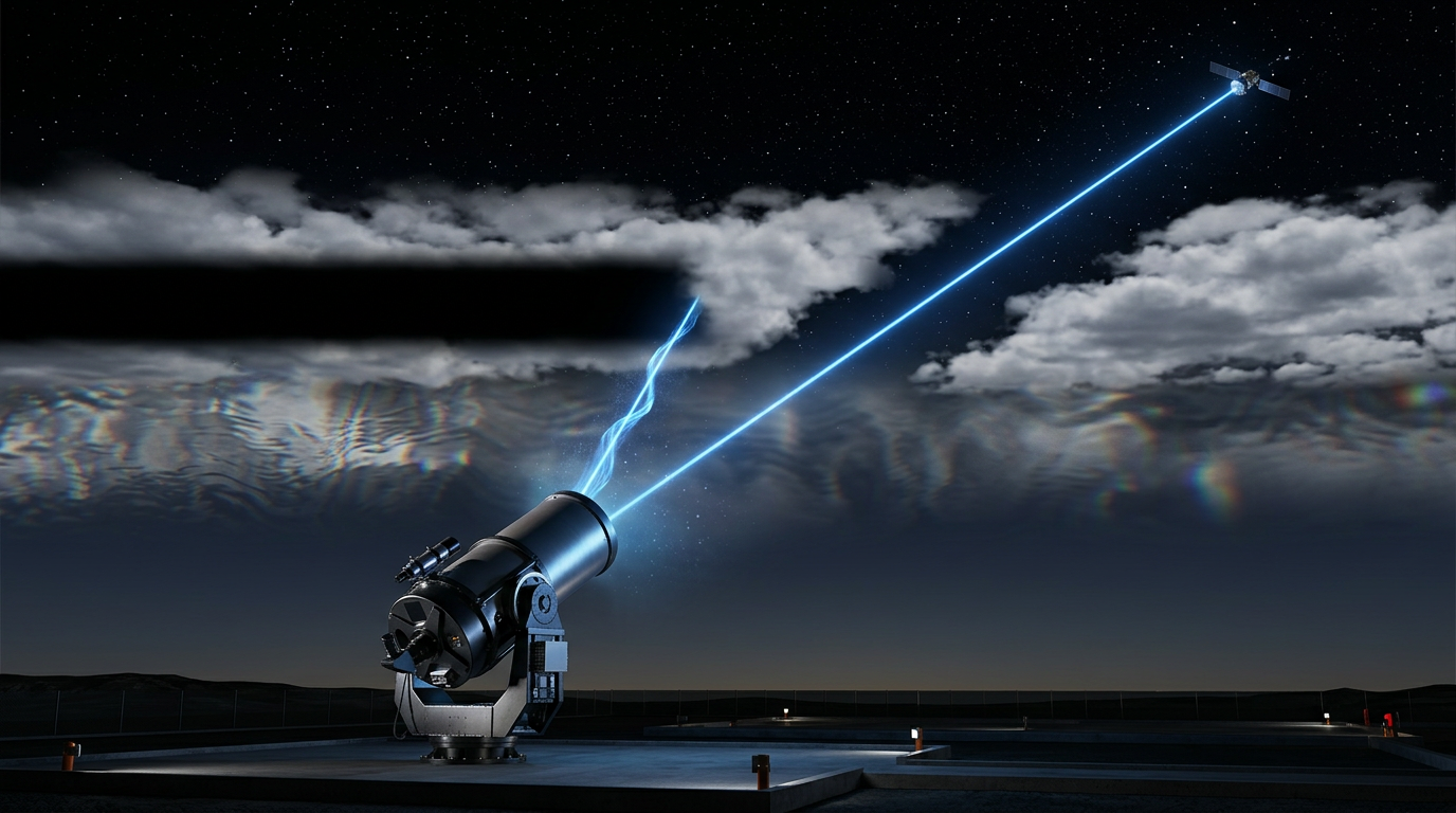
Even with a perfect pointing system, a space-to-ground optical link must contend with something an inter-satellite link never faces: Earth's atmosphere. The key asymmetry is that uplinks are affected more severely than downlinks. A downlink beam travels through vacuum for the vast majority of its path and only enters the turbulent lower atmosphere near the end of its journey. An uplink beam, by contrast, enters the turbulent layer immediately upon leaving the ground — traversing it in full when the beam is at its most concentrated, compounding both divergence and wavefront distortion across the entire atmospheric column.
The primary turbulence mechanism is scintillation: random refractive-index variations, driven by temperature and pressure gradients, cause the beam to wander spatially, spread beyond its diffraction-limited size, and produce rapid intensity fluctuations at the receiver. NASA technical reports characterise these fades as lasting on the order of a few milliseconds — long enough to wipe out an entire data packet — with 10 dB fades occurring roughly 1% of the time under moderate turbulence conditions and more than 10% of the time under worst-case conditions.
Cloud blockage is categorically different from turbulence and must be understood separately. An opaque cloud imposes attenuation exceeding 100 dB — effectively a complete link outage. No terminal-level mitigation addresses this: adaptive optics, larger apertures, and increased transmit power are all irrelevant when a cloud sits in the beam path. Cloud blockage is a network architecture problem, not a hardware problem.
A third impairment — molecular absorption and aerosol scattering — attenuates the beam as it passes through the atmosphere. Wavelength selection is the primary response: 1550 nm sits in a favourable atmospheric transmission window (discussed in the Background section), which is one of the reasons it has become the dominant wavelength for space optical communications.
Engineers have four principal strategies for managing these impairments:
- Adaptive optics (AO): An AO system at the OGS measures the incoming wavefront distortion using a wavefront sensor and pre-corrects the uplink beam before transmission. This partially compensates turbulence-induced distortion by the time the beam reaches the spacecraft receiver. AO addresses turbulence only — it has no effect on cloud blockage.
- Site diversity: Deploying multiple geographically dispersed OGS sites ensures that cloud cover at any one location does not block all links simultaneously. A DLR study cited in NASA technical literature found that 11 sites distributed across Europe could achieve 99.67% availability for a GEO satellite, while 8 carefully placed sites across Europe and Africa reached 99.971%. Site diversity is the primary network-level response to cloud blockage.
- Aperture averaging and multi-beam uplinks: A larger receive aperture averages intensity fluctuations across its area, reducing the variance of received power from scintillation. Spatially separated transmit apertures on the uplink similarly average out scintillation along the path. These techniques reduce the statistical severity of fades without eliminating them.
- Link margin sized to availability requirements: Because scintillation fades are statistical rather than deterministic, designers must build sufficient margin into the link to survive the fade depth that will be exceeded only a small fraction of the time. NASA analyses indicate that a 20 dB margin is needed to maintain link operation 99.9% of the time under worst-case scintillation conditions.
The statistical nature of atmospheric losses is the key design insight this step establishes. Unlike free-space path loss, which is fixed by geometry, atmospheric impairments vary continuously and must be treated as a margin item governed by a required availability level. That framing carries directly into the link budget treatment in the next step.
Scintillation fades are probabilistic: the link budget must be sized to survive the worst fade that occurs within the required availability window, not just the mean atmospheric loss. This is fundamentally different from accounting for free-space path loss, which is deterministic.
Step 8
Link budget fundamentals for optical communication terminals
Key Insights
Link closes when received power exceeds sensitivity threshold.
Aperture diameter is the primary transmit/receive lever.
Free-space path loss scales with range squared.
All parameters trade against each other under SWaP.
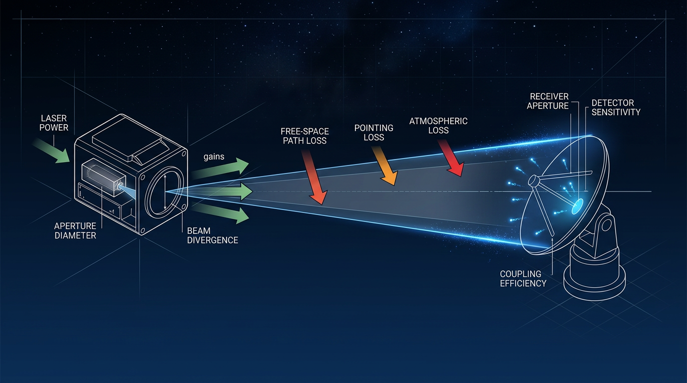
A link budget is a power accounting exercise: the designer tallies every gain and every loss between the transmitter and the receiver to determine whether enough signal photons arrive to support the required data rate at an acceptable bit error rate.
The link is said to close when received power exceeds the receiver's sensitivity threshold — and every design decision on an optical communication terminal ultimately traces back to whether the link closes under the required conditions.
Transmit-side parameters
Three parameters govern how much optical power enters the propagation path from the transmitter.
- Laser output power: The raw optical power produced by the laser source. More power increases the signal level at the receiver, but higher-power lasers draw more electrical power and generate more heat — both constrained by spacecraft SWaP budgets.
- Transmit aperture diameter: The diameter of the telescope or lens through which the beam is projected. A larger aperture concentrates the beam more tightly, directing more power toward the receiver at a given range. It is the single most influential transmit-side design lever.
- Transmit optics efficiency: The fraction of laser power that actually exits the terminal after passing through internal optical elements. Reflective losses, absorption, and alignment imperfections all reduce this figure, and they compound across multiple optical surfaces.
The relationship between aperture size and beam divergence is worth understanding intuitively: divergence decreases as aperture diameter increases, meaning a larger aperture produces a narrower beam that stays concentrated over longer distances.
This narrowing effect is why aperture is such a powerful design lever — but it also tightens the pointing requirement, because a narrower beam is harder to keep precisely aimed at a distant receiver. The transmit aperture therefore simultaneously shapes both the link budget and the PAT system specification.
Free-space path loss and the optical advantage
Free-space path loss is the dominant loss term for any long-distance optical link. Signal power at the receiver falls with the square of the range — double the distance, and received power drops to one quarter of its former level.
This inverse-square relationship makes range the most unforgiving constraint in the link budget, and it is why aperture and power scale up together as link distances grow.
Optical carriers occupy a frequency roughly four to five orders of magnitude higher than Ka-band radio. This means an optical beam can carry far more information per unit of transmitted power than an equivalent RF link at the same range — which is the fundamental physics that makes optical communication terminals the natural path beyond the RF bandwidth ceiling.
Receive-side parameters
The receive side determines how much of the arriving optical power is converted into a usable signal.
- Receiver aperture area: A larger receiving telescope intercepts more of the expanding beam, collecting more photons per unit time. For ground stations, apertures can be made relatively large; for spacecraft receivers, SWaP again limits how big the aperture can be.
- Detector sensitivity: Characterised by quantum efficiency (the fraction of arriving photons that produce a detection event) and the detector's noise floor. Higher quantum efficiency and lower noise allow the system to close the link at lower received power levels.
- Coupling efficiency: The fraction of collected light that reaches the detector itself after passing through focusing optics, fibres, or other internal elements. Losses here reduce the effective signal level before detection occurs.
For space-to-ground links, the atmospheric impairments covered in §7 — turbulence-induced fading and absorption — must be included in the budget as a statistical loss term, with a link margin sized to the required availability level.
This is a probabilistic treatment, not a deterministic one: the designer asks what loss level is exceeded only a small fraction of the time, then ensures the budget holds a margin sufficient to close the link at that percentile. Inter-satellite links, operating entirely in vacuum, carry no atmospheric loss term.
The residual pointing error from the PAT system — discussed in §6 — enters the budget as a pointing loss term. Beam misalignment reduces the fraction of transmitted power falling on the receiver, so PAT accuracy is a direct input to the link budget, not a separate engineering concern.
All of these parameters trade against each other within the bounds set by spacecraft SWaP. A smaller aperture can be compensated by higher transmit power or a more sensitive detector; a longer link demands larger apertures or greater power; tighter pointing reduces the margin required for pointing loss.
This is why link budget analysis is a central design activity from the earliest mission concept phase — it is the framework that makes every subsystem trade-off legible and ensures that choices in aperture, laser, detector, and PAT combine into a coherent, closeable system.
Step 9
The commercial and government ecosystem driving OCT adoption
Key Insights
RF congestion makes optical the only viable path.
SDA PWSA and EDRS are live deployments now.
Limited qualified suppliers remain a structural bottleneck.
SDA and CCSDS standards compliance cuts programme risk.
The shift from RF to optical is grounded in physics, not preference. RF spectrum is congested, licensed, and bandwidth-limited; optical spectrum is unregulated and orders of magnitude wider, making it the only viable path for high-throughput satellite constellations once RF capacity is exhausted.
Government programmes have progressively de-risked the technology across the full range of mission profiles. NASA's LLCD demonstrated 622 Mbps from lunar orbit in 2013; LCRD has been providing GEO relay at up to 1.244 Gbps coded rate from geosynchronous orbit; and DSOC has demonstrated optical links from deep space at ranges between 0.1 and 2.7 AU.
Taken together, these programmes have shown that optical links are viable across LEO, GEO, and deep-space profiles — providing the confidence base that justifies commercial and defence procurement at scale.
| Programme | Orbit / Range | Demonstrated Rate | Status |
|---|---|---|---|
| NASA LLCD | Lunar orbit (~400,000 km) | 622 Mbps downlink | Completed 2013–2014 |
| NASA LCRD | GEO relay | 1.244 Gbps coded rate | Operational (launched Dec 2021) |
| NASA DSOC | Deep space (0.1–2.7 AU) | Up to 267 Mbps at 0.25 AU | Demonstration ongoing |
| ESA EDRS (Tesat LCTs) | GEO relay, up to 45,000 km ISL | 1.8 Gbps | Operational service |
| SDA PWSA Tranche 1 | LEO constellation | OCT + Ka-band RF | Launches underway (2025) |
A comparative table of the key government OCT programmes gives technically literate readers a clear, scannable reference for the milestone demonstrations that have de-risked the technology — the data is genuinely comparative across mission profile, data rate, and distance.
The single most consequential current deployment by volume is the US Space Development Agency's Proliferated Warfighter Space Architecture (PWSA). Tranche 1 comprises 126 transport layer satellites, each equipped with optical communications terminals and Ka-band RF, with launches confirmed from Vandenberg Space Force Base.
The PWSA is the primary force pushing OCT suppliers from bespoke, low-volume fabrication toward genuine mass production — a transition that is pulling unit costs down across the industry, including for commercial LEO constellation operators.
The operational benchmark for sustained ISL performance is ESA's European Data Relay System (EDRS), using Laser Communication Terminals developed by Tesat-Spacecom. EDRS has established over 10,000 inter-satellite links at up to 1.8 Gbps over distances of up to 45,000 km — not a demonstration, but a running relay service.
The supply side presents a recognised structural challenge. The number of qualified OCT suppliers with in-orbit-verified hardware has historically been very limited, and this constraint is a genuine bottleneck for constellation operators trying to scale.
Tesat-Spacecom has established a US manufacturing subsidiary to meet growing SDA and commercial demand. Mynaric has ramped volume production of its CONDOR Mk3 terminal, delivering over 100 units to customers including a complete launch set for an SDA Tranche 1 prime, though production ramp-up has faced real difficulties including component shortages and yield challenges.
The difficulty Mynaric encountered in scaling production illustrates a broader point: mass manufacturing an optical terminal is a fundamentally different engineering problem from building one in small numbers, and the industry is still working through that transition.
The SDA OCT Standard (Version 4.0.0, June 2024) defines interoperability specifications for terminals operating within the PWSA. CCSDS has published approved Blue Book standards for optical communications physical layer (141.0-B-1) and coding and synchronisation (142.0-B-1), both issued August 2019. Hardware locked to a proprietary standard carries programme risk as the standards landscape evolves; terminals and ground components that support both SDA and CCSDS modes are better positioned for cross-programme compatibility.
The commercial pull is reinforcing the government push. LEO constellation operators across Earth observation, broadband, and data relay are driving demand for affordable OCTs, and the challenge — as the SpaceNews analysis of laser link adoption put it — is making terminals producible at an economic cost and schedule that systems can afford.
Conclusion
From fundamentals to operational reality
You now hold a working picture of the optical communication terminal: what it is, how it behaves differently across vacuum and atmospheric paths, what makes it genuinely hard to build, and why the physics of congested RF spectrum has made it the only credible path forward for high-throughput space communications.
The natural next questions — ground-segment architecture, the standards landscape, and the supplier ecosystem — are well-defined and worth pursuing.
OCTs are no longer demonstration hardware. The transition to operational infrastructure is already underway, and the fundamentals you now understand are the right foundation for engaging with it.
Frequently asked questions about optical communication terminals
Browse the questions below for direct answers to common queries about optical communication terminals, from technical fundamentals to the standards and supplier landscape.
An optical communication terminal (OCT) encodes data onto a laser beam operating at optical frequencies — typically around 1550 nm in the near-infrared — using spectrum that requires no licensing. An RF transponder uses radio-wavelength signals across licensed, coordinated spectrum bands regulated by national authorities and the ITU. The two technologies differ fundamentally in bandwidth, beam geometry, and pointing demands. Optical links carry orders of magnitude more data than RF links of comparable size and power, because the higher frequency supports far wider usable bandwidth. The OCT beam divergence is measured in microradians — producing a spot only a few kilometres across at lunar distances — whereas an RF beam at Ka-band from a comparable aperture spreads to thousands of kilometres. That narrow beam is both the advantage and the constraint: it concentrates signal energy on the target with exceptional efficiency, but it requires precise pointing, acquisition, and tracking (PAT) that RF systems simply do not need. An RF system with a 1-metre antenna at Ka-band requires pointing accuracy of a few milliradians — well within standard spacecraft attitude control. An optical terminal demands sub-microradian accuracy, which requires a dedicated two-stage pointing system.
Three factors converge to make 1550 nm the dominant wavelength choice. First, it sits within a favourable atmospheric transmission window, reducing absorption losses on space-to-ground links. Second, it is significantly safer for human eyes than 1064 nm — the cornea and lens absorb 1550 nm energy before it reaches the retina, raising the damage threshold by orders of magnitude compared to shorter wavelengths. Third, the global telecoms industry has spent decades producing high-performance erbium-doped fibre amplifier (EDFA) components at 1550 nm, giving designers access to mature, flight-heritage parts rather than custom development. The 1064 nm wavelength was used in earlier deep-space demonstrations — notably as the uplink beacon wavelength in NASA's Deep Space Optical Communications (DSOC) experiment — but 1550 nm has become the clear engineering choice for the downlink and for most near-Earth systems. The combination of atmospheric performance, eye-safety margin, and component availability makes it the practical standard, and it is the wavelength range specified in the CCSDS Optical Communications Physical Layer standard for cross-agency interoperability.
An inter-satellite link (ISL) connects two spacecraft entirely within the vacuum of space — there is no atmosphere to traverse, so the link is governed purely by geometry, pointing accuracy, and transmit power. A space-to-ground optical link must pass through Earth's atmosphere for the final portion of its path, introducing turbulence, scintillation, and the possibility of complete blockage by cloud cover. ISLs are therefore more predictable and offer higher availability: they are unaffected by weather and operate continuously once pointing is established. Space-to-ground links are essential for delivering data to end users on Earth, but they require mitigation strategies — principally site diversity (multiple geographically dispersed ground stations) and adaptive optics at the ground terminal. ISLs are used for constellation mesh networking and data relay; ESA's European Data Relay System (EDRS) uses GEO-to-LEO ISLs to relay Copernicus Sentinel data at 1.8 Gbps over distances up to 45,000 km. Space-to-ground links are used for final delivery from orbit to ground infrastructure, and are the link type most sensitive to ground-station design and siting decisions.
No. Opaque clouds impose attenuation that effectively causes a complete link outage — measured values exceed 100 dB for cumulus clouds, and calculated extinctions for dense cloud or fog can exceed 1000 dB. Unlike atmospheric turbulence, cloud blockage cannot be corrected at the terminal level: larger apertures, adaptive optics, and higher transmit power offer no remedy against an opaque cloud obscuring the line of sight. The only viable mitigation is at the network level: deploying multiple geographically dispersed optical ground stations (OGS) so that cloud cover at one site does not block all links simultaneously. Site selection also matters — high-altitude, low-latitude, dry-climate locations experience cloud blockage less frequently. Studies cited in the literature show that 8 carefully placed ground terminals across Europe and Africa can achieve 99.971% aggregate link availability, and that 10 sites in southern Europe alone can achieve 99.89%. The practical design implication is clear: a single-site ground segment is not viable for reliable optical communications; an OGS network is a system requirement, not an optional enhancement.
Currently, there are no spectrum licensing requirements for laser (optical) communications in space. The ITU Radio Regulations define radio waves as electromagnetic waves at frequencies arbitrarily below 3000 GHz. Optical communications operate at frequencies around 193 THz — far above that threshold — placing them outside the ITU's spectrum coordination framework entirely. RF systems require licensing because their broad beams share spectrum and can interfere with one another across wide geographic areas; a regulatory body must coordinate assignments to prevent harmful interference. Optical beams are so narrow and directional that interference between independent systems is not a meaningful concern, so no equivalent coordination regime exists. This is one of the practical advantages of optical communications for constellation operators: terminals can be deployed without the spectrum coordination overhead, filing delays, and coordination negotiations that RF requires. Note that this applies specifically to spectrum licensing — other regulatory frameworks, such as those governing export controls or orbital slot coordination, remain applicable to satellite programmes regardless of the communications technology used.
The SDA OCT Standard (Version 4.0.0, published 28 June 2024) is a design reference published by the US Space Development Agency (SDA) that specifies the interface and performance requirements for optical communication terminals used in the Proliferated Warfighter Space Architecture (PWSA). It matters because it mandates interoperability: a constellation operator can mix terminals from different qualified suppliers — provided all are built to the standard — and those terminals will communicate with each other. This was demonstrated in practice when SDA Tranche 0 satellites from different prime contractors successfully established cross-vendor laser links. The interoperability requirement directly addresses the structural challenge posed by the limited number of qualified OCT manufacturers: when terminals from different suppliers are compatible, operators are not locked to a single source and the supply-side bottleneck becomes less acute. Version 4.0.0 also introduces a long-range waveform targeting future connectivity with medium Earth orbit missile-tracking satellites, extending the standard's scope beyond LEO. Standards-compatible ground terminals — hardware that supports SDA, CCSDS, and other modes — similarly reduce programme risk as the standards landscape continues to evolve.
An optical ground station (OGS) is not a passive receiver — it is an active participant in the link. Its functions include: collecting the downlink beam through a large-aperture telescope; applying adaptive optics to correct wavefront distortion introduced by atmospheric turbulence; transmitting an uplink beacon laser that the spacecraft terminal uses as a pointing reference for its PAT system; and, in bidirectional configurations, transmitting a data uplink channel back to the spacecraft. The quality of the OGS uplink is a genuine engineering variable in overall link performance, not an afterthought. A weak or poorly configured uplink beacon degrades pointing, acquisition, and tracking performance on the spacecraft, which in turn reduces downlink quality — the two ends of the link are tightly coupled. Ground station siting (altitude, latitude, local cloud climatology) and aperture size also affect link closure directly. ESA's Optical Ground Station on Tenerife, for example, uses a 1-metre Zeiss telescope at 2,400 metres altitude and has been used to commission and test optical terminals on numerous ESA and international spacecraft. The OGS is therefore a system-level design variable that operators must specify carefully alongside the space segment.
The number of qualified, in-orbit-verified optical communication terminal suppliers is small — this is a recognised structural challenge in the industry. Two suppliers have the most prominent positions in the current market. Tesat-Spacecom has the longest in-orbit heritage: its Laser Communication Terminals (LCTs) have been deployed on EDRS, Alphasat, and Copernicus Sentinel satellites, and the company has reported over 10,000 laser links established in orbit. Its SCOT80 terminal, with 62 units in orbit across multiple prime contractors' satellites as of late 2025, is compliant with the SDA OCT Standard. Mynaric has entered volume production for SDA-standard terminals: as of mid-2025, the company had delivered more than 100 CONDOR Mk3 terminals and manufactured more than 150 optical heads, supplying terminals for Northrop Grumman, Raytheon, and other PWSA prime contractors. The limited supplier base has driven both operator interest in interoperability standards — reducing single-supplier dependency — and broader industry efforts to develop additional qualified sources. The SDA's requirement for cross-vendor interoperability is itself a direct response to this structural constraint, ensuring that programmes can mix suppliers as the market matures.