

Introduction
Spacecraft and satellites are generating more data than traditional radio frequency systems can comfortably return to Earth — and that gap is widening as sensors, imaging payloads, and constellation architectures grow more ambitious.
This guide is written for engineers and system architects who want to understand how free-space optical communication actually works, for programme managers and procurement leads weighing its maturity and operational constraints, and for researchers building on the mission record so far.
What follows covers the physics of the link, the engineering challenges that dominate real programme risk, what demonstrated missions have proved in practice, and where the technology is heading — honestly, without overselling it.
TL;DR
Laser communications in space has moved well past the demonstration phase, but the engineering challenges — particularly pointing stability and ground-segment reliability — remain the deciding factors in whether a programme succeeds.
Understanding both what makes it work and what makes it hard is the only solid basis for a programme decision.
This article covers:

How FSO links work end to end
Pointing, acquisition, and tracking challenges
Atmospheric effects and mitigation strategies
NASA milestones: LLCD, LCRD, DSOC
Applications, limitations, and hybrid architectures
Regulatory landscape and standardisation
What is laser communications in space?
Every space mission faces the same constraint: the faster it generates data, the harder it becomes to get that data home. Free-space optical (FSO) communication — also called lasercom — addresses that constraint directly, by transmitting data on modulated laser beams propagating through free space rather than through fibre-optic cables or radio-frequency channels.
The medium can be vacuum, as in a link between two spacecraft, or atmosphere, as in a link between a spacecraft and a ground station. Either way, the underlying physics is the same: information is encoded onto an optical carrier and sent wirelessly between terminals. This is the technology the entire guide examines.
FSO versus RF: the same physics, different frequencies
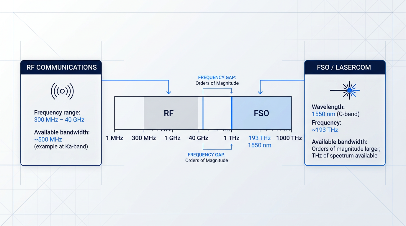
Both FSO and conventional radio frequency (RF) systems encode data onto electromagnetic waves. The critical difference is where on the spectrum each operates. As the NASA State of the Art of Small Spacecraft Technology report describes, RF spacecraft communications systems typically operate within IEEE radio bands of 300 MHz to 40 GHz, while FSO links operate at much higher frequencies — generally in the near-infrared bands at wavelengths such as 1064 nm or 1550 nm.
That frequency difference is not incidental — it is the root physical reason FSO can support far higher data rates. Higher carrier frequencies mean wider available bandwidth, and wider bandwidth directly enables higher data throughput. As NASA's SOA report states, the higher frequencies used in lasercom mean the amount of bandwidth available for communicating is much larger compared to RF, and that increase in bandwidth enables much higher data rates.
Beam divergence: one physical fact, two consequences
The short wavelengths of FSO signals produce a second defining characteristic: beam divergence is proportional to wavelength divided by transmitter aperture diameter. Because optical wavelengths are orders of magnitude smaller than RF wavelengths, lasercom transmitter apertures and beam divergence can also be made much smaller.
This single physical fact has two consequences that run through the rest of this guide. First, it is the source of FSO's size, weight, and power (SWaP) advantage: a compact optical aperture can produce a narrower, more concentrated beam than an RF dish of comparable size, enabling lasercom systems to be lighter and draw less power than similarly performing RF systems. Second, it is the source of FSO's primary engineering challenge: a narrower beam is harder to keep precisely aimed at a moving target across thousands of kilometres.
Both consequences flow from the same source. Understanding that duality — narrower beam as both asset and demand — is the prerequisite for everything that follows in this guide about pointing systems, link stability, and terminal design.
Why 1550 nm? The case for the C-band window
FSO links operate at near-infrared wavelengths, with 1550 nm — the telecommunications C-band — as the dominant choice for space links, though 1064 nm is also used in a number of missions and is not absent from the field.
Three converging factors make 1550 nm the preferred operating wavelength for most space FSO programmes.
- Atmospheric transmission window: The 1550 nm band sits in a low-absorption region of the atmosphere, meaning less signal loss on ground-to-space paths compared with many other wavelengths.
- Component supply chain maturity: 1550 nm is the backbone of terrestrial fibre-optic telecom. Erbium-doped fibre amplifiers (EDFAs), modulators, and detectors built for that industry are directly applicable to space FSO, reducing development cost and risk.
- Eye-safety advantage: 1550 nm has a substantially higher eye-damage threshold than 1064 nm — remaining eye-safe at orders of magnitude higher power — which matters for ground operations and regulatory considerations.
The eye-safety advantage is quantitatively significant. NASA NTRS analysis using ANSI standards shows that the maximum eye-safe exposure at 1550 nm is orders of magnitude higher than at 1064 nm or 532 nm under the same pulse conditions. As one NASA NTRS paper summarises the wavelength selection rationale: 1550 nm was chosen for its eye-safety advantage, better atmospheric transmission, multiple-vendor commercial availability, and excellent integrated receivers.
The supply-chain argument is equally concrete. As NASA NTRS documentation of early FSO flight systems notes, the choice of 1550 nm allows flight hardware to leverage the heavy investment the fibre-optic telecommunications industry has made in 1550 nm laser systems, while simultaneously making the downlink beam eye-safe even directly in front of the aperture.
Atmospheric transmission, a mature EDFA supply chain inherited from terrestrial fibre-optic telecom, and a substantially higher eye-safety threshold than 1064 nm all point to the same wavelength — which is why 1550 nm has become the dominant choice for space FSO links.
The three fundamental link types
A space communications architecture is defined by three link types, each with a distinct geometry and engineering character. NASA's SOA documentation establishes all three as the standard framework for describing spacecraft communications.
- Uplink: Ground station to spacecraft. Commands and data travel from Earth up to the vehicle in orbit or beyond.
- Downlink: Spacecraft to ground station. Mission data, telemetry, and science observations travel from the spacecraft back to Earth.
- Crosslink (inter-satellite link, ISL): Spacecraft to spacecraft. Data passes directly between vehicles without routing through a ground station.
FSO applies across all three link types. The engineering challenges differ by geometry — an ISL operates in vacuum between two resource-constrained spacecraft, while a downlink must contend with atmospheric effects at the receiving end — but the underlying optical physics is common to each. Later sections address those differences in detail.
Inside a lasercom terminal
A lasercom terminal (LCT) is structured analogously to an RF transceiver: there is a transmit chain, a propagation medium, and a receive chain. At the component level, NASA's SOA report identifies three core elements that typically comprise an LCT.
- Optical modem: Modulates data onto the optical carrier for transmission and demodulates the received optical signal back into data.
- Optical amplifier: Boosts the signal to the power level required to close the link across the intended range. EDFAs are the prevalent technology at 1550 nm.
- Optical head: The telescope and pointing mechanism that transmits and receives the beam — the optical equivalent of an RF antenna and gimbal assembly.
This three-component scaffold — modem, amplifier, head — is the mental model the rest of this guide builds on. Later sections examine each element in greater depth, along with the pointing systems that keep the optical head locked onto its target.
What drives adoption: the capability advantages
The motivating case for FSO is grounded in measurable performance differences. NASA programme documentation notes that, depending on the mission application, an optical communications solution could achieve a 50% saving in mass, a 65% saving in power, and up to a 20-fold increase in data rate compared with conventional RF systems. Separately, IEEE space communications literature describes optical links as offering data rates 10 to 100 times higher than comparable RF systems at lower transmitter mass and power.
Beyond raw data rate, the narrow beamwidth of a lasercom link produces two security-relevant properties: low probability of intercept (LPI) and low probability of detection (LPD). The small illuminated footprint at the receiver drastically reduces the geographic area where a link can be intercepted, as NASA's optical communications overview notes.
Two further advantages reflect the technology's operating environment rather than its physics. First, optical frequencies are currently unregulated: unlike RF systems, which require a licensing process to communicate with a spacecraft, there are presently no licensing requirements for laser communications. Second, the highly directional nature of lasercom beams means the technology encounters very little interference with other systems.
| Characteristic | RF (typical spacecraft bands) | FSO / Lasercom |
|---|---|---|
| Operating frequency | 300 MHz – 40 GHz (IEEE radio bands) | Near-infrared, e.g. ~193 THz at 1550 nm |
| Available bandwidth | Limited; e.g. ~500 MHz at Ka-band (32–38 GHz) | Orders of magnitude larger; THz of spectrum available |
| Beam divergence | Wide; large antenna needed for directivity | Very narrow; compact aperture sufficient |
| SWaP vs. comparable RF | Baseline | Up to 50% mass saving, 65% power saving (NASA) |
| Data rate advantage | Baseline | Up to 10–100x higher (IEEE); up to 20x (NASA) |
| Spectrum licensing | Required (FCC/NTIA/ITU) | Currently none required |
| Intercept / interference risk | Wider footprint; higher intercept area | Low probability of intercept and detection (LPI/LPD) |
FSO and RF spacecraft communications compared across key performance and operational characteristics. Data rate figures are from NASA programme documentation and IEEE space communications literature.
The pattern across these axes is consistent: FSO trades the engineering complexity of precise pointing for substantial gains in throughput, SWaP, security, and spectrum freedom. Those trade-offs are not abstract — they are why programmes from deep-space science missions to commercial satellite constellations are investing in the technology.
With the conceptual foundations in place — what FSO is, how it differs from RF at the physical level, why 1550 nm dominates, what the three link types are, and how an LCT is structured — the next step is to trace how a lasercom link actually works from end to end, beginning at the laser source and following the signal through to detection at the receiver.
How an FSO link works: transmitter to receiver
An FSO link can sound deceptively simple: shine a laser at a detector across a gap of hundreds or thousands of kilometres. In practice, it is a carefully engineered chain of components, each performing a specific transformation on the optical signal, connected by the physics of free-space propagation.
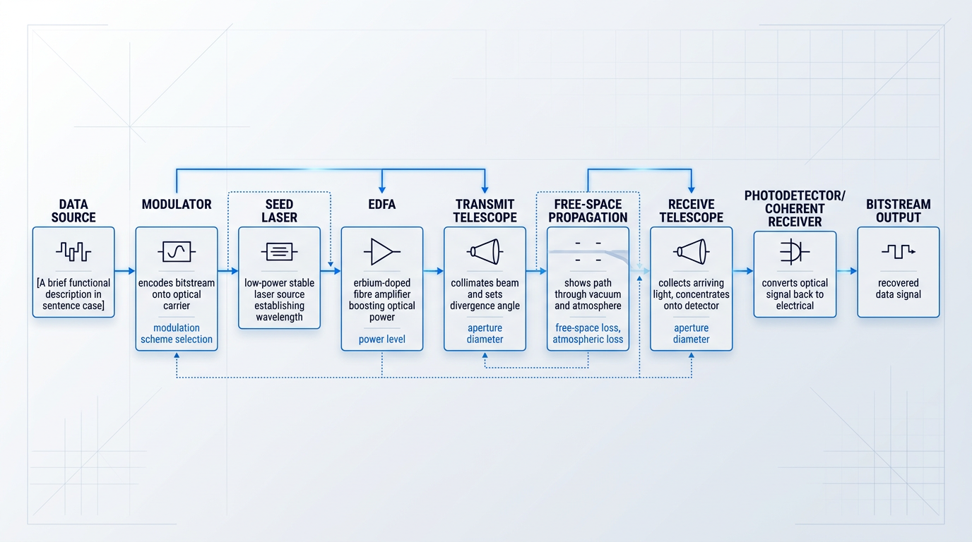
The end-to-end signal path
The chain begins at the data source, where the raw bitstream to be transmitted enters the optical terminal.
A modulator encodes that bitstream onto an optical carrier — impressing the data onto the light by varying its intensity, phase, or pulse timing, depending on the modulation scheme chosen.
The modulated signal originates from a seed laser: a low-power, highly stable laser source that establishes the precise wavelength of the optical carrier.
Because the seed laser alone rarely produces enough power to close a link over significant distances, the signal passes next to an erbium-doped fibre amplifier (EDFA), which boosts the optical power to the level needed for the link.
This seed-laser-plus-EDFA arrangement, known as a master oscillator power amplifier (MOPA) architecture, is a standard transmit configuration in lasercom terminals, used in both spacecraft downlink systems and ground-based uplink systems.
The amplified beam then enters the transmit telescope aperture, which collimates the diverging light from the fibre into a narrow, well-directed beam aimed at the distant receiver.
That beam then propagates across free space — through vacuum for most of a satellite link, and through the atmosphere for the portions of the path near the ground.
At the far end, the receive telescope aperture collects the arriving light and concentrates it onto a detector.
The detector — either a direct-detection photodetector or a coherent receiver, depending on the modulation scheme — converts the optical signal back into an electrical signal, from which the original bitstream is recovered.
Modulation: encoding data onto light
The modulation scheme determines how the bitstream is impressed onto the optical carrier, and the choice involves a genuine trade-off between implementation complexity and receiver sensitivity.
On-off keying (OOK) is the simplest approach: the laser is switched on to represent a '1' and off to represent a '0', encoding binary data in the presence or absence of light pulses.
OOK's low complexity makes it straightforward to implement, but it is less photon-efficient than alternatives — a consideration that matters most when received power is constrained.
Pulse-position modulation (PPM) takes a different approach, encoding information in the timing of pulses rather than their presence or absence — a given pulse appears in one of several possible time slots, and its position within that window carries the data.
PPM extracts more bits per detected photon than OOK, making it the preferred modulation for deep-space links where received optical power is severely limited.
Coherent modulation schemes such as differential phase-shift keying (DPSK) and quadrature phase-shift keying (QPSK) encode data in the phase of the optical carrier rather than its intensity, achieving higher receiver sensitivity than intensity-based schemes — but requiring phase tracking at the receiver, which adds complexity.
NASA's TeraByte InfraRed Delivery (TBIRD) CubeSat mission demonstrated 200 Gbps using a dual-polarisation QPSK waveform, illustrating how coherent schemes suit near-Earth links where high throughput is the priority.
| Scheme | Encoding Principle | Detection Type | Photon Efficiency | Representative Application |
|---|---|---|---|---|
| OOK | Data in pulse presence/absence | Direct detection | Lower — less photon-efficient than PPM or coherent schemes | Near-Earth direct-to-Earth links; favoured for lower complexity |
| PPM | Data in pulse timing within a time slot | Direct detection (photon-counting) | High — preferred where received power is scarce | Deep-space links where received power is severely limited |
| DPSK | Data in phase difference between symbols | Coherent | Higher than OOK | Near-Earth links requiring improved receiver sensitivity |
| QPSK | Data in carrier phase quadrature states | Coherent | High — multiple bits per symbol | High-throughput near-Earth links; TBIRD demonstrated 200 Gbps DP-QPSK |
Optical modulation schemes compared by encoding principle, detection type, photon efficiency, and representative application.
The pattern across these schemes is consistent: moving from OOK toward coherent modulation increases photon efficiency and throughput, but demands progressively more sophisticated receivers and signal processing.
For mission designers, the choice is rarely about which scheme is objectively better — it is about which trade-off fits the link geometry, the available power budget, and the acceptable receiver complexity.
The link budget: closing the link
A link budget is the accounting framework that determines whether a given FSO link is viable: the received optical power, after all losses, must exceed the receiver's sensitivity threshold.
The key factors on the transmit side are the transmit power delivered by the amplifier and the transmit aperture, which collimates the beam and sets its divergence angle.
A telescope's far-field beam divergence is approximately equal to the wavelength divided by the aperture diameter, meaning a larger aperture produces a narrower, more concentrated beam.
The dominant loss term for any long link is free-space loss, which follows an inverse-square relationship: received power falls with the square of the link distance.
Doubling the link distance reduces the received optical power by a factor of four. This is why deep-space links require either very large ground-station receive apertures or high transmit power — or both — to close the link at all.
On the receive side, a larger receive aperture collects more of the arriving light, directly improving the link margin — but in daytime operation it also collects more background solar noise, which degrades the signal-to-noise ratio.
Additional loss terms include pointing loss (arising from imperfect beam alignment) and atmospheric loss on links that pass through the atmosphere — both of which must be accounted for before a link can be declared closable.
Aperture size: a genuine engineering trade-off
Aperture size is not a simple 'bigger is better' decision on either end of the link.
A larger transmit aperture narrows the beam, concentrating more power onto the distant receiver — but the smaller beam footprint at the receiver means the pointing system must hold alignment to a correspondingly tighter angular tolerance.
A larger receive aperture collects more signal, improving link margin — but also collects more background light during daytime passes, increasing the noise floor against which the signal must be detected.
These competing pressures mean aperture sizing is always a system-level decision, balancing link margin, pointing capability, and operational environment — a trade-off that becomes particularly acute when the beam divergence is measured in microradians.
Downlink, uplink, and inter-satellite links
The three link geometries behave differently in propagation, and those differences shape the link budget in distinct ways.
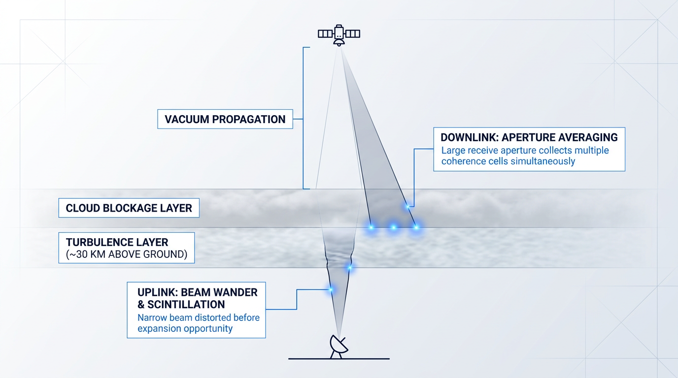
On a downlink (spacecraft to ground), the beam travels through vacuum for the vast majority of its path; atmospheric effects are confined to roughly the final 30 km before the ground terminal.
A large ground telescope also benefits from aperture averaging on the downlink: the collecting area partially smooths out the intensity fluctuations caused by atmospheric turbulence, because the telescope aperture is large relative to the turbulence scale.
The uplink (ground to spacecraft) presents a harder atmospheric problem: the beam enters the atmosphere immediately on leaving the ground terminal, before it has had the opportunity to expand significantly.
Turbulence distorts the beam early in its path, spreading the far-field intensity pattern at the spacecraft in ways that are more severe than in the downlink case.
The spacecraft's receive aperture is also typically small relative to a ground telescope, which means the aperture averaging advantage is not available for uplink applications — the phase coherence radius is much larger than the probable receiving aperture on a spacecraft.
For inter-satellite links (crosslinks) between spacecraft in vacuum, the atmosphere is absent entirely: the link budget is governed by free-space loss and pointing accuracy alone, with no atmospheric loss term to account for.
The dominant engineering challenges for crosslinks shift accordingly: pointing across a dynamic geometry between two moving spacecraft, managing Doppler shifts on the optical carrier, and operating within the tight power and mass constraints of two space terminals.
The aperture and divergence trade-offs established here are what make beam pointing so demanding in practice — and that challenge is examined in depth in the next section on pointing, acquisition, and tracking.
Pointing, acquisition, and tracking: the hardest problem
A transmit beam divergence of a few microradians sounds like a technical detail until you consider what it means in practice: the beam footprint at a ground station is smaller than a city block, and the spacecraft generating it is moving at orbital velocity while vibrating from within. The gap between where a spacecraft thinks it is pointing and where it actually needs to point — the gap that pointing, acquisition, and tracking (PAT) must close — spans several orders of magnitude. No other subsystem in a laser communications terminal faces a performance requirement this severe.
Quantifying the pointing challenge
The numbers frame the problem precisely. For a typical FSO terminal, the transmit beamwidth is on the order of a few microradians, and for deep-space terminals the required pointing accuracy is a small fraction of a microradian — well below one microradian.
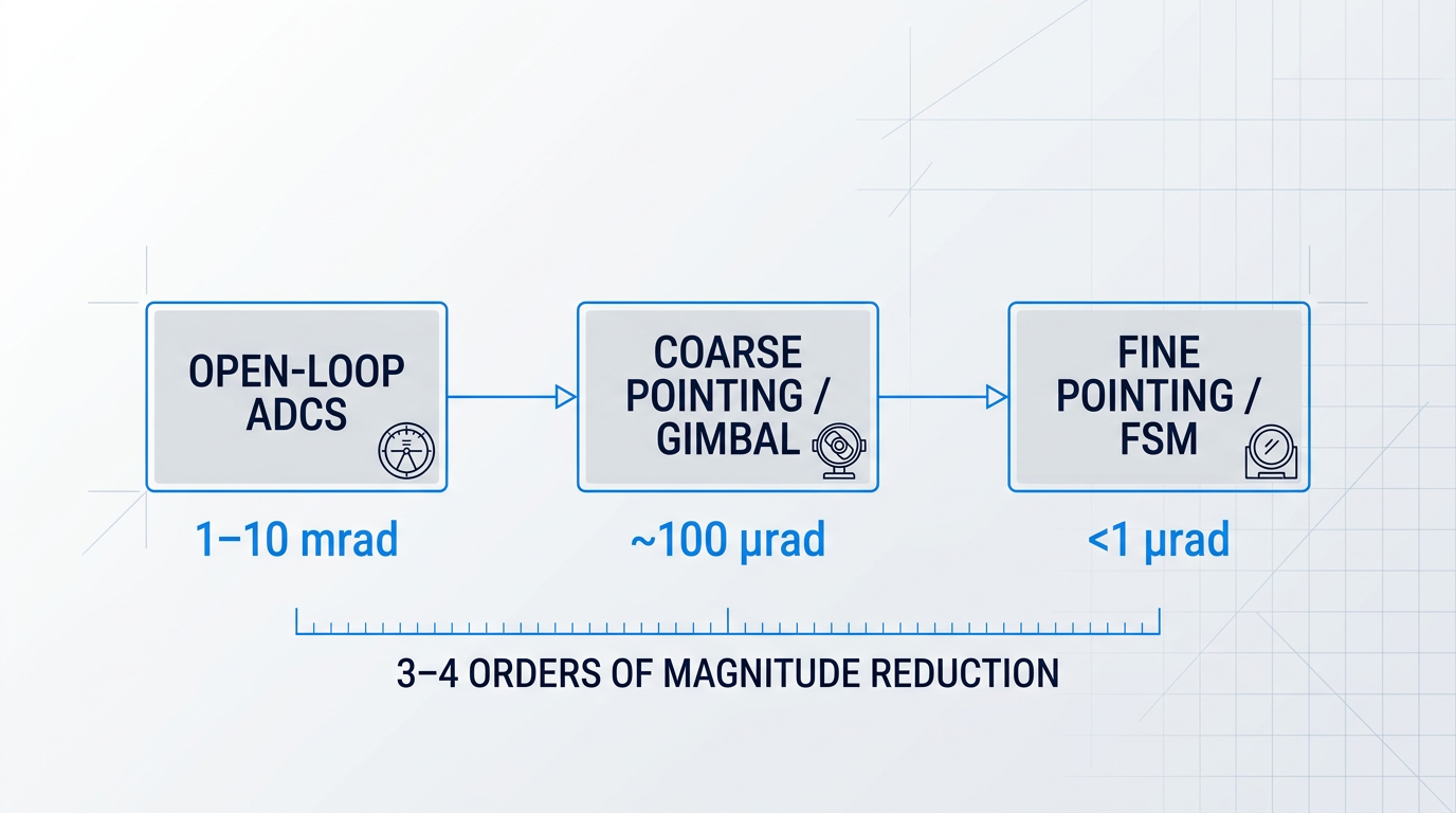
The initial open-loop pointing uncertainty of a space platform, by contrast, is typically in the range of 1 to 10 milliradians — the accuracy achievable from spacecraft attitude knowledge alone, before any closed-loop correction is applied.
That gap — from milliradians of open-loop uncertainty to sub-microradian closed-loop accuracy — represents a reduction of three to four orders of magnitude that the PAT system must deliver in real time, continuously, throughout every communications pass.
A space platform's open-loop pointing uncertainty is typically 1–10 milliradians. The required pointing accuracy for a deep-space laser terminal is a fraction of a microradian. The PAT system must bridge this gap — a reduction of several orders of magnitude — in real time.
Two-stage pointing architecture: coarse and fine
No single mechanism can span this range efficiently, so FSO terminals universally employ a two-stage architecture operating in series, each stage reducing the residual error passed to the next.
The first stage is coarse pointing, typically implemented through the spacecraft's ADCS (attitude determination and control system), sometimes augmented by a gimbal assembly that extends the pointing field of regard. The ADCS slews the spacecraft body — and with it the optical terminal — to bring the target into a region the fine stage can handle. Its job is not precision; it is range reduction.
The second stage is fine pointing, implemented with fast steering mirrors (FSMs) located in the optical beam path within the terminal. An FSM is a small, lightweight mirror mounted on high-bandwidth actuators that can redirect the beam with sub-microradian resolution, responding to error signals at rates far beyond what any spacecraft body or gimbal could achieve.
The two stages are complementary by design: coarse pointing brings uncertainty down to a range where the FSM's limited angular stroke is sufficient, and the FSM then achieves the submicroradian accuracy needed to close the data link. The ILLUMA-T terminal on the International Space Station, for example, used a gimbal for coarse closed-loop pointing and a backend optics assembly FSM for high-frequency disturbance rejection and fine pointing — a configuration representative of current operational systems.
Beacon-aided acquisition
Before the data link can be established, the two terminals must find each other — and with a beam divergence of a few microradians, neither can simply sweep until it hits the target. The standard solution is a beacon laser transmitted from the ground terminal toward the spacecraft.
The beacon is transmitted at higher power and with a broader beam divergence than the data beam, making it detectable even when the spacecraft's initial pointing is imprecise. Once the spacecraft terminal detects and locks onto the beacon, it has a precise angular reference: the direction from which the beacon is arriving tells the terminal where the ground station is.
With the beacon acquired and tracked, the spacecraft uses that reference to point its narrower data beam back at the ground terminal, applying any necessary offset corrections. The beacon is not purely a pointing aid — it can also carry modulated data, serving a dual communications and navigation function. The NASA SOA survey notes that ground-to-space beacons for low-Earth orbit missions are typically tens of watts of optical power, reflecting the need to be detectable across the pointing uncertainty region.
Spacecraft vibration and jitter
Even after acquisition, maintaining the link is complicated by a persistent internal threat: spacecraft vibration. The primary sources are reaction wheels — the spinning momentum wheels used for attitude control — along with thermal cycling as the spacecraft moves between sunlight and shadow, and structural resonance modes excited by any of these disturbances.
These vibrations couple into the optical terminal and produce high-frequency jitter in the pointing direction. The scale is significant: measurements on the LANDSAT spacecraft, for instance, identified a pointing jitter of approximately 11 microradians integrated out to 125 Hz — many times the width of a typical FSO transmit beam.
Suppressing jitter of this magnitude to achieve submicroradian pointing accuracy requires both passive and active approaches. Vibration isolators mounted between the spacecraft structure and the optical terminal attenuate high-frequency disturbances before they reach the optics. Active suppression is then provided by high-bandwidth servo loops — the same FSM that handles fine pointing also continuously corrects for residual jitter, driven by error signals derived from the tracked beacon position.
The servo bandwidth required is demanding: analysis of LANDSAT jitter data indicates that achieving the necessary jitter suppression requires servo bandwidths of 1,000 Hz or more, with tracking detector bandwidths of 5,000 to 10,000 Hz to feed the control loop adequately. This is a significant driver for the design of high-performance PAT systems.
Point-ahead correction
There is a geometric complication that persists even after jitter is suppressed: the transmitter cannot aim at the receiver's current apparent position, because light takes a finite time to travel the link distance, and both platforms are moving.
By the time the transmitted beam arrives at the receiver, the receiver will have moved — potentially by a significant angular distance as seen from the transmitter. The transmitter must therefore aim slightly ahead of the receiver's apparent position, with the angular offset determined by the relative transverse velocity between the two platforms and the one-way light travel time. This is the point-ahead correction.
The required correction varies with the geometry. For near-Earth applications such as LEO-to-ground links, the point-ahead angle is typically on the order of tens of microradians — around ±80 µrad for LEO-to-GEO geometry. For deep-space terminals, where the light travel time is vastly longer, the required correction grows to several hundreds of microradians, and must be computed and applied open-loop because it is generally impractical to offset the beacon and receiver location at precisely the point-ahead angle.
The correction must be updated continuously as the geometry changes throughout the pass, making it a dynamic calculation rather than a fixed offset. Both the magnitude and the direction of the point-ahead vector change over time, and errors in its computation translate directly into pointing errors on the data beam.
The acquisition sequence
Before tracking can begin, the two terminals must complete an acquisition sequence — the process of establishing mutual line-of-sight from an initial state of uncertainty. This is a coordinated procedure, not a single action.
- Initial open-loop pointing: Both terminals point at each other's predicted position using ephemeris data and spacecraft attitude knowledge, accepting the 1–10 mrad open-loop uncertainty.
- Beacon transmission and scan: One terminal transmits a wider-divergence beacon and scans it across the uncertainty region; the other searches its field of view for the beacon signal.
- Beacon detection and lock: On detecting the beacon, the receiving terminal locks onto it, establishing a line-of-sight reference and halting the acquisition scan.
- Data beam handover: With the beacon tracked, the spacecraft points its narrow data beam back at the ground terminal, progressively narrowing pointing uncertainty as closed-loop tracking is established.
NASA's Lunar Laser Communications Demonstration (LLCD) provided a definitive proof point for this process. In October 2013, LLCD demonstrated automated pointing, acquisition, and tracking of a 15 microradian beam from lunar orbit — showing that the acquisition problem, though genuinely hard, is solvable with well-engineered systems operating from a spacecraft at lunar distances.
The ILLUMA-T mission on the ISS illustrated the operational detail of this process: the terminal transmitted a 260 microradian beacon in a spiral scan pattern across a ±1 mrad acquisition field of view, with scan parameters carefully traded against acquisition time and probability. In June 2024, 85% of all acquisitions were completed within five minutes — a benchmark that reflects the maturity of current PAT system design.
Inter-satellite link PAT: an additional layer of complexity
When both terminals are aboard spacecraft in different orbital planes, the PAT challenge intensifies considerably. Both platforms are moving simultaneously, relative velocities between satellites in different orbits can be high, and Doppler shifts on the received signal can be large enough to require special consideration in the receive optics design.
PAT updates must occur at high rates to track the rapidly changing geometry, and an advanced opto-mechanical system is typically needed to meet these requirements. Inter-satellite links are covered in depth later in this guide; the key point here is that the PAT architecture for ISLs inherits all of the challenges described above and adds the complication of two moving, resource-constrained platforms rather than one.
Beaconless pointing: an alternative architecture
Not all PAT systems rely on a ground beacon. Beaconless pointing replaces the beacon signal with celestial references — stars, the Earth, the Moon — observed by a star tracker aboard the spacecraft to derive the pointing reference from known celestial mechanics rather than from a transmitted signal.
The appeal is clear: no high-power beacon laser is required at the ground station, reducing ground infrastructure complexity and cost, and the approach extends naturally to deep-space missions where transmitting a detectable beacon across vast distances becomes impractical. A star tracker-based beaconless system has demonstrated a total pointing accuracy of better than 850 nanoradians (3σ) from anywhere in the solar system — a figure that meets the submicroradian requirements of deep-space lasercom links.
The trade-off is implementation difficulty. The spacecraft must derive its pointing knowledge entirely from onboard measurements of celestial sources, combining star tracker data with high-bandwidth gyroscopes to propagate the pointing solution between updates. This demands tighter integration between the optical terminal and the spacecraft's attitude and navigation systems, and is generally harder to make robust than beacon-aided acquisition. Both architectures are in operational use; the choice depends on mission geometry, ground infrastructure constraints, and the available pointing budget.
With the PAT challenge understood in full — the orders-of-magnitude gap to close, the two-stage architecture that closes it, and the vibration, geometry, and acquisition problems that complicate every link — the next obstacle the beam faces is the atmosphere itself, which introduces a separate family of degradation mechanisms that PAT systems cannot address.
How the atmosphere degrades FSO ground links
Solving the pointing challenge brings the beam to the edge of the atmosphere — but the final 30 km above a ground station introduce a second, independent set of degradation mechanisms that better pointing cannot fix. For laser communications in space, the atmosphere is not a neutral medium: it scatters, distorts, and sometimes blocks the optical beam entirely, imposing constraints that shape how ground networks are designed and operated.
Turbulence, scintillation, and beam distortion
Atmospheric turbulence originates in temperature gradients within the lower atmosphere that produce localised, continuously varying fluctuations in the refractive index of air. These fluctuations act as a dynamic, distributed lens system that distorts any optical beam propagating through them. The Kolmogorov turbulence model is the standard theoretical framework for characterising these fluctuations and predicting their effect on optical propagation.
The key site-characterisation parameter is the Fried coherence length, r₀ — the spatial scale over which the optical wavefront remains approximately coherent. A larger r₀ indicates a less turbulent atmosphere: the wavefront stays coherent across a wider aperture, making correction easier. Because r₀ varies with site elevation, time of day, season, and telescope elevation angle, turbulence strength is not a fixed property of a location but a statistical characterisation that drives both site selection and adaptive optics system design.
Scintillation is the dominant atmospheric performance-degradation mechanism for FSO ground links under clear-sky conditions. Small-scale refractive-index variations act like a distribution of weak, randomly positioned lenses that continuously focus and defocus the beam, producing a time-varying speckle pattern of bright and dark regions across the receive aperture. Critically, scintillation produces burst errors — clusters of lost bits concentrated in time — rather than uniform noise, which has direct implications for the design of error-correction codes and link-layer protocols.
Turbulence also produces two geometrically distinct effects on the beam itself. Beam wander occurs when large-scale eddies — those larger than the beam diameter — displace the beam centroid laterally, so the beam arrives at a different position on the receive aperture from moment to moment. Beam spreading occurs when smaller-scale eddies broaden the beam's angular extent beyond its diffraction-limited divergence, reducing peak power density at the receiver even when the centroid is on target.
The relative importance of these two effects differs between link directions: beam wander is the more significant concern for uplinks, where the beam is still narrow as it enters the atmosphere; beam spreading is more relevant for downlinks, where the beam has already expanded to many metres in diameter before encountering the turbulent layer.
Uplink versus downlink: an important asymmetry
The geometry of the two link directions produces a fundamental asymmetry in how severely turbulence affects them. On the downlink (spacecraft to ground), the beam travels through vacuum for the vast majority of its path and only enters the atmosphere in the final portion of the link. By that point, the beam has expanded to many metres in diameter, so small-scale turbulence eddies perturb only a fraction of the wavefront. A large receive aperture then performs aperture averaging — collecting light from many independently fluctuating coherence cells simultaneously — which substantially reduces the scintillation variance seen at the detector.
The uplink (ground to spacecraft) is considerably more vulnerable. The beam leaves the transmit aperture while it is still narrow and immediately enters the turbulent atmosphere, which distorts the wavefront before the beam has had any opportunity to spread. The result is a scintillating, wandering intensity pattern at the spacecraft that degrades both the beacon signal used for pointing and any uplink data channel. This asymmetry is a recurring engineering consideration in FSO ground network design and motivates specific uplink mitigation strategies.
Cloud cover: the link's hardest constraint
Turbulence degrades an FSO link; cloud cover ends it. Thick cloud layers attenuate an optical beam to the point of complete link outage, and no practical increase in transmit power overcomes a dense overcast. This is the critical distinction from radio-frequency links, where rain fade can be partially countered by increasing transmit power within a manageable fade margin — optical links require cloud-free line of sight (CFLOS) as an absolute precondition for operation.
Fog and low-lying aerosols also cause significant attenuation, but they typically occupy a shallower layer than cloud and affect a smaller fraction of overall link time. Cloud cover remains the dominant concern, and its impact is not uniformly distributed: a single ground station at a mid-latitude site may be cloud-free for less than half of all potential contact windows.
Unlike turbulence, which can be partially corrected at the link level, cloud blockage cannot be engineered away by improving the terminal. It requires a network-level response: distributing ground stations across geographically separated sites so that no single weather system can simultaneously block all of them.
The operational consequence is that site diversity — not link-level engineering — is the only effective response to cloud cover, and it shapes how FSO ground networks are architected from the outset.
Mitigation strategies: turbulence and cloud cover
Adaptive optics (AO) is the primary engineering response to turbulence on the downlink. A wavefront sensor — typically a Shack-Hartmann sensor — measures the phase distortions across the incoming beam; a deformable mirror with many independently actuatable segments then applies a conjugate correction in real time, restoring the wavefront to near-flat. AO is particularly critical for coherent detection schemes such as DPSK and QPSK, which must couple received light into single-mode fibre: a distorted wavefront cannot be efficiently coupled, so without AO the receiver's sensitivity advantage is largely lost. NASA's Laser Communications Relay Demonstration (LCRD) has conducted extensive AO experiments from its GEO orbit, establishing a body of operational data on AO performance under real atmospheric conditions.
For site diversity, the principle is straightforward: if a single optical ground station (OGS) is cloud-free for a fraction p of the time, a network of N stations sited far enough apart to experience statistically independent weather has a combined availability approaching 1-(1-p)^N. Two stations each available 60% of the time together achieve roughly 84% network availability; three stations push that figure towards 94%. The key requirement is statistical independence — stations must be separated by hundreds of kilometres to avoid being under the same weather system simultaneously.
LCRD demonstrated this approach with its two optical ground stations: one at Table Mountain, California (JPL's Optical Communications Telescope Laboratory) and one at Haleakalā, Hawaii — geographically separated enough to provide meaningfully independent weather windows and together substantially improving the fraction of contact opportunities that could be used productively.
On the uplink, a complementary strategy involves transmitting through multiple spatially separated sub-apertures rather than a single aperture. Because each sub-beam travels through a slightly different atmospheric path, their turbulence-induced intensity fluctuations are partially uncorrelated; at the spacecraft, the combined intensity is more stable than any individual beam alone. This multi-beam uplink averaging is the transmit-side counterpart to aperture averaging on the receive side, and the specific hardware configurations that implement it are covered in the ground station architecture section that follows.
A further operational constraint worth noting is solar background interference. FSO receivers are extremely sensitive, and solar radiation at the signal wavelength can overwhelm the detector when the Sun lies near the beam path. Narrow-band optical filtering centred on the signal wavelength is the standard mitigation, supplemented by operational planning that avoids link geometries placing the Sun within the receiver's field of view.
Understanding these atmospheric impairments and the engineering responses they demand sets the stage for examining how optical ground stations are actually built to manage them — from telescope aperture and AO subsystem design to multi-aperture uplink arrays and site selection criteria.
Optical Ground Station Architecture and Uplink Amplification
Point a radio dish at the sky and it collects whatever falls into its aperture — surface roughness, pointing error of a fraction of a degree, none of it matters much at centimetre wavelengths. An optical ground station (OGS), by contrast, must house a precision mirrored telescope whose primary surface is figured to a small fraction of the operating wavelength, and whose mount must track a moving spacecraft to within a few microradians. The physics of 1550 nm leaves no margin for the tolerances that RF engineers take for granted.
Site selection is the first engineering decision, and it follows the same logic astronomers have applied for decades: high altitude, arid climate, and proximity to existing telescope infrastructure.
Altitude places the station above the densest, most turbulent layer of the atmosphere, reducing the integrated path length through air that causes the beam wander and scintillation described in the previous section. Arid climates minimise cloud-cover probability, which is decisive — cloud blocks the link entirely, and no amount of adaptive optics recovers a photon that never arrived. NASA's Laser Communications Relay Demonstration (LCRD) illustrates the rationale directly: its two OGS sites are JPL's Optical Communications Telescope Laboratory (OCTL) at Table Mountain, California, and the station at Haleakalā, Maui, Hawaii. Northrop Grumman analysis found Haleakalā's atmospheric coherence length (r₀) had a median of 43.5 cm at 1550 nm, compared with 20.0 cm at Table Mountain — a substantially more benign turbulence environment that is reflected in the site's superior simultaneous cloud-free line-of-sight statistics when paired with OGS-1.
Key subsystems of an optical ground station
A full-capability OGS is not a single instrument but an integrated stack of subsystems, each solving one part of the link problem simultaneously.
- Receive telescope and mount: Precision mirrored telescope on a fast-tracking alt-azimuth or elevation-over-azimuth mount; OCTL uses a 1 m f/76 coudé focus design.
- Adaptive optics system: Corrects wavefront distortion on coherent downlinks to enable efficient single-mode fibre coupling into the ground modem.
- Pointing and tracking system: Wide-field acquisition camera for initial lock-on, fast steering mirrors for fine correction of beam wander during the link.
- Downlink receiver and modem: Photodetector or coherent receiver at the telescope focal plane, followed by demodulation and decoding electronics.
- Uplink transmit optics and laser amplifier: High-power amplified laser beam directed through the transmit aperture toward the spacecraft terminal.
- Beacon laser system: Provides the pointing reference the spacecraft terminal acquires and tracks; may share the uplink beam or use a separate path.
- Atmospheric monitoring: Scintillation sensors, seeing monitors, and weather instrumentation to characterise link conditions in real time.
These subsystems must operate in concert from the moment acquisition begins. The adaptive optics and fast steering mirrors — whose underlying principles were established in the atmospheric impairments section — are the mechanisms that translate site-selection advantage into actual link margin.
Uplink beacon functions and the single-beam architecture
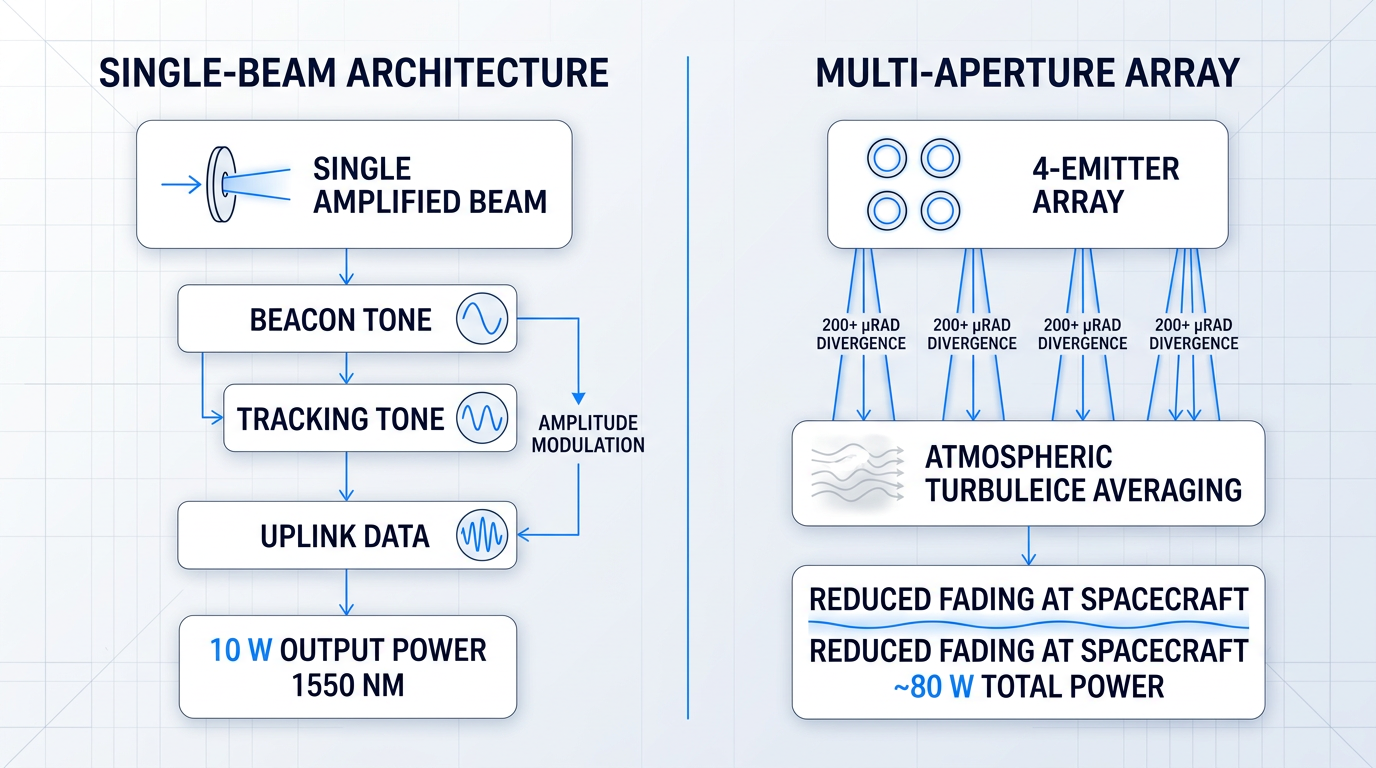
Every OGS must perform three uplink functions: transmit a beacon signal that the spacecraft terminal acquires for coarse pointing, maintain a tracking tone that the terminal uses for fine pointing stabilisation, and carry uplink data.
The conventional approach separates these into distinct optical paths — one beam for the beacon, one for data — but maintaining two independently aligned transmit paths adds component count and alignment complexity to the ground terminal.
The alternative is a single amplified beam carrying both functions simultaneously, with amplitude modulation nesting the tracking beacon tone at a low modulation depth and the data signal above it in the same beam.
Achieving sufficient irradiance at the spacecraft aperture over LEO or lunar distances requires a high-power amplifier. The NASA SOA Communications 2024 report notes that typical ground-to-space beacons for LEO missions are in the tens-of-watts range. At 1550 nm, the technology that delivers this power with near-diffraction-limited beam quality is the erbium-doped fibre amplifier (EDFA) — the same class of device that underpins the global fibre-telecom infrastructure, with a mature component supply chain and well-understood performance at the wavelengths discussed earlier in this guide.
The LCRD OGS-2 laser subsystem illustrates the power levels involved: a custom photonics assembly producing a low-power fibre-coupled signal, followed by a high-power optical amplifier capable of up to 10 W, limited to 7.3 W by software during operation, with 5.4 W emitted into free space after telescope and dome losses.
Woodrow Scientific's EDF-UL is a purpose-built EDFA for satellite ground-station uplinks that leads on the single-beam beacon-and-data architecture: the tracking beacon rides at low modulation depth and the uplink data above it in one amplified beam, eliminating the need for a separate beacon optical path entirely.
The amplifier delivers 10 W average output power at 1550 nm (higher on request) with M² < 1.1 beam quality, operating across three modes — acquisition, tracking, and data-transmission — with a beacon and tracking frequency range from CW to 10 MHz and sinusoidal or rectangular waveforms selectable in software.
What distinguishes the EDF-UL most comprehensively is the depth of its end-to-end configurability across both hardware and software layers. Hardware configuration covers band (C-band, L-band, or dual-band from a single source), output power, direction (beacon-only or bi-directional), 2- and 4-emitter array support with multi-station synchronisation, an external optical input port to amplify third-party transmitters at OOK up to 20 Mbps, ±2 nm wavelength tunability around the seed, and a choice of air or water cooling — all specified to the client's ground station.
The software layer is Woodrow Scientific's Modulation-on-Demand: software-selectable amplitude modulation throughout the link, with adjustable waveform, frequency, and modulation index, the beacon and tracking tone combined with data modulation via TTL, and the ability to switch to CCSDS or SDA standards at high power across C/L-band, plus an integrated-seed uplink to 10 Mbps (OOK).
FSO standards — CCSDS, SDA, and proprietary protocols — are still evolving. Ground-station uplink hardware that can switch modulation scheme, waveform, and beacon behaviour in software, without hardware replacement, remains compatible as those standards mature. The EDF-UL's Modulation-on-Demand implements this in practice: switchable to CCSDS or SDA at high power across C/L-band from the same physical unit.
Behind the product is Woodrow Scientific Limited, a UK manufacturer founded in 2012 that designs, builds, qualifies, and supports its amplifiers entirely in-house, on patented technology, backed by over 200 years of combined engineering experience rooted in Southampton's Optoelectronics Research Centre — the birthplace of the EDFA.
This matters in practice because a significant portion of the EDFA market is served by resellers and importers rather than original manufacturers — which typically means limited engineering support, slower access to spares, and no ability to adapt the product to programme-specific requirements at either the hardware or software level.
The EDF-UL ships in a 3U 19" rack form factor, with USB, RS232, and Parallel I/O interfaces, and carries CE and UKCA certification.
Multi-aperture uplink arrays and site diversity
Transmitting the uplink through a single aperture concentrates all the beam energy through one turbulent atmospheric column, which causes the far-field irradiance at the spacecraft to scintillate — the uplink fading problem noted in the atmospheric impairments section.
Splitting the uplink across multiple sub-apertures — spatially diverse, mutually incoherent beams — averages the turbulence-induced fluctuations in the far field, producing a more stable irradiance at the spacecraft terminal and reducing pointing error on the spacecraft side.
LCRD OGS-1 at Table Mountain demonstrates this in operation: its uplink beacon is composed of four beams, each with divergence in excess of 200 µrad, spatially separated across the 1 m primary mirror to reduce fading at the spacecraft. The LCOT ground terminal takes this further, with four independent 15 cm transmit telescopes each backed by a high-power optical amplifier, targeting approximately 80 W total uplink power.
The EDF-UL supports 2- and 4-emitter array configurations with synchronisation and is compatible with multi-station diversity network architectures, making it directly applicable to both emitter-diversity and site-diversity deployment strategies.
High-power uplink beams transmitted through navigable airspace require formal coordination with aviation authorities before operations begin.
In the United States, any laser operation with the potential to exceed safe irradiance levels in navigable airspace must be notified to the FAA, which conducts an aeronautical review under Advisory Circular AC 70-1. For missions operating under DoD authority, the DoD Laser Clearing House registers and deconflicts laser activities to protect orbiting assets and personnel in space. NASA missions are subject to review by the NASA Laser Safety Review Board, which assesses safety analyses and plans for any NASA laser with the potential to emit above the horizon and interfere with air traffic or orbiting assets.
The operational mechanism is predictive avoidance (PA): software computes time windows during which the beam path is clear of aircraft and sensitive satellites, and the beam is shuttered automatically when a conflict is predicted. The OCTL LLOT demonstration used a LabVIEW-based controller that shuttered the beacon throughout each pass based on an extended avoidance cone around the uplink beams.
At 1550 nm, the EDF-UL's output falls in the wavelength range classified as Class 4 under IEC 60825-1 — the highest laser hazard class, requiring engineering controls and appropriate eyewear. The 1550 nm wavelength carries a higher maximum permissible exposure threshold than 1064 nm, because the cornea absorbs it before it reaches the retina, but this does not reduce the regulatory obligations: Class 4 laser safety procedures apply in full.
The broader regulatory landscape — spectrum coordination, export controls, and international frameworks — is covered in the regulatory section later in this guide; the treatment here is specific to the OGS operational context.
Everything described in this section — the site selection trade-offs, the subsystem complexity, the uplink amplifier architecture, the aviation coordination — is specific to the Earth-to-space segment of an FSO link, where the atmosphere is the defining engineering constraint. The next section examines what happens when both terminals are in space: the atmospheric challenges disappear, but a different set of constraints — resource limitations, high relative velocities, and the absence of any ground infrastructure — take their place.
Optical Inter-Satellite Links: FSO Without the Atmosphere
Every section so far has placed one end of the FSO link on the ground, where the atmosphere is the dominant engineering problem. Optical inter-satellite links (OISLs) remove that problem entirely: both terminals are in vacuum, atmospheric impairment is absent, and the link budget is governed only by free-space path loss and pointing accuracy. But the atmosphere's exit is not the end of the challenge — it is the beginning of a different one.
What OISLs Enable: The Architectural Value Proposition
When satellites can route data directly to one another, a spacecraft over the mid-Pacific or a polar region no longer needs a ground station within its footprint to downlink data — it can relay through the constellation to a station elsewhere, at the speed of light through vacuum.
This changes the economics of global coverage: a mesh of OISLs means fewer ground stations are needed for continuous service, latency is reduced because data travels through space rather than bouncing to ground and back, and high-throughput routing between orbital planes becomes possible without touching the terrestrial network.
Why FSO Rather Than RF for Inter-Satellite Crosslinks
RF crosslinks are a mature technology, but they carry structural disadvantages in dense constellations that optical crosslinks avoid.
- No spectrum licensing: Optical frequencies are currently unregulated, unlike RF systems which require a licensing process — a significant operational advantage at constellation scale.
- No adjacent-satellite interference: The narrow optical beam produces no interference with neighbouring satellites, unlike RF crosslinks which can create interference problems in dense constellations.
- Far higher data rates: Optical crosslinks support data rates far beyond what RF crosslinks achieve for equivalent mass and power, owing to the much wider available bandwidth.
- Cleaner link budget in vacuum: Without an atmospheric term, the ISL link budget is governed only by free-space path loss and pointing — more predictable than any ground link.
The NASA State of the Art of Small Spacecraft Technology document notes that lasercom terminals can offer a smaller footprint and lower power draw compared to RF terminals — an advantage that matters on both ends of an ISL, where every kilogram and watt competes with propulsion, power, and payload systems.
PAT and Doppler: How the ISL Environment Changes the Problem
The PAT challenge covered earlier takes on a different character in the ISL regime, because the geometry and resource constraints are fundamentally different from a ground link.
Satellites in different orbital planes can have high relative velocities, creating rapid angular rate changes that the pointing system must track continuously at high update rates — an advanced opto-mechanical system is required to manage this dynamic environment.
Those same high relative velocities produce significant Doppler shifts on the received optical signal: the received frequency is shifted relative to the transmitted frequency by an amount proportional to the relative velocity and inversely proportional to the wavelength, and the receive optics and signal processing must be designed to accommodate and compensate for this shift continuously.
Critically, there is no large ground aperture to absorb pointing errors or link margin shortfalls: both ends of an ISL are resource-constrained space terminals, so the system must be engineered to close the link without the asymmetry that a well-resourced ground station provides.
Commercial Deployment at Scale: Starlink and Project Kuiper
SpaceX first deployed laser crosslinks on Starlink satellites launched to polar orbit in January 2021, specifically because polar regions lack ground station coverage — as Elon Musk noted at the time, the links meant no ground stations were needed over the poles.
The decision was then extended fleet-wide: SpaceX announced that all future Starlink satellites would carry laser crosslinks, with the capability enabling satellites to communicate across the same or adjacent orbital planes and reducing the number of ground stations needed for global coverage.
Amazon's Project Kuiper demonstrated what the technology can achieve at peak performance: KuiperSat-1 and KuiperSat-2 maintained a two-way 100 Gbps optical link for around an hour at a time, with the two prototype satellites nearly 1,000 km apart — and the technology is designed to operate across distances up to 2,600 km.
The Kuiper demonstration also illustrated a physics advantage of optical ISLs over ground fibre: light travels faster through vacuum than through glass, meaning data can traverse a satellite constellation roughly 30% faster than through terrestrial fibre-optic cables.
Telesat Lightspeed: A Purpose-Designed Mesh Architecture
Telesat Lightspeed takes the mesh concept further by designing it into the constellation from the outset: each satellite carries four 10 Gbps optical ISLs arranged front, back, left, and right, connecting to both in-plane and adjacent satellites to form a global mesh network in space.
Onboard digital signal processing handles satellite-to-satellite and satellite-to-ground data routing directly, so traffic can flow from any user terminal to any destination on Earth without relying on ground-based switching — the routing intelligence lives in the constellation itself.
SDA Transport Layer: A Government Interoperability Standard
The US Space Development Agency's Proliferated Warfighter Space Architecture (PWSA) uses OISLs as the backbone of its planned mesh network of data transport and missile-tracking satellites in LEO, and has formalised this through a published interoperability standard.
The SDA OISL Standard (Version 2.1.2) specifies the physical and data-link layer requirements for space-to-space and space-to-ground optical links in the SDA Tranche 0 system: terminals operate in the optical C-band, with a nominal data rate of 312.5 Mbps and an upper bound of 1 Gbps, using OOK-NRZ modulation.
The standard's core purpose is multi-vendor interoperability: terminals from different manufacturers must be able to acquire and sustain a link with one another, which requires tight specification of wavelengths, modulation, acquisition timing, and link margin at range.
In the Tranche 0 on-orbit demonstration, laser terminals built by German firm TESAT successfully acquired link and maintained it for several hours — well within the standard's 100-second acquisition requirement, though above the 10-second stretch goal, according to SDA Director Derek Tournear.
EDRS: The Most Mature Operational OISL System
The European Data Relay System (EDRS) — ESA's SpaceDataHighway — is the benchmark for operational OISL maturity: two GEO nodes fitted with laser communication terminals built by TESAT-Spacecom relay data from LEO Earth observation satellites, including the Copernicus Sentinels, to European ground stations in near real time.
The TESAT terminals lock onto a moving target up to 45,000 km away and exchange data at up to 1.8 Gbit/s — a GEO-to-LEO geometry that represents one of the longest operational optical ISLs in service.
The system's operational record makes the case for OISL reliability more concisely than any specification: EDRS has completed 75,000 links with LEO satellites and transmitted over 4.5 petabytes of data to Europe, accumulating more than one million minutes of communications with Sentinel satellites and the International Space Station.
EDRS has completed 75,000 operational links and transmitted 4.5 petabytes of data. SpaceX has committed laser crosslinks to its entire Starlink fleet. Amazon demonstrated 100 Gbps two-way throughput between prototype satellites. The technology is deployed, operational, and scaling.
What EDRS demonstrates, above all, is that optical ISLs work reliably at operational tempo over very long distances — the link count and petabyte figures are not laboratory results, they are the accumulated output of a system in continuous commercial and governmental service.
Link Budget in Vacuum: Distance, Aperture, and Data Rate
The ISL link budget follows the same inverse-square law introduced earlier in this guide: received power falls with the square of distance, so doubling the link range requires either four times the transmit power or a proportional increase in aperture to maintain the same data rate.
In vacuum, this calculation is cleaner than for any ground link because there is no atmospheric loss term — the budget is determined entirely by transmit power, aperture geometry, pointing loss, and free-space path loss, which is a function of distance and wavelength alone.
The SDA standard's range margin requirements illustrate this directly: links beyond 5,000 km carry only 1 dB of required margin, while links up to 5,000 km carry 3 dB — the tighter margin at long range reflects the steeper power penalty the inverse-square law imposes as distance grows.
With commercial and government OISL deployment now well established across LEO constellations and GEO relay architectures, the next thread to follow is the NASA demonstration programme that proved the underlying optical communications technology through a series of progressive milestones — from lunar orbit to deep space.
EDFAs Engineered for Free-Space Optical Links
The amplifier at the heart of an FSO terminal shapes link performance. Explore our custom EDFAs built specifically for free-space optical communications, or download the EDF-UL-10 datasheet for full specifications.
NASA Laser Communications Milestones: What the Missions Proved
Performance figures for laser communications in space are only as useful as the engineering questions they answer. The missions covered here — LLCD, LCRD, ILLUMA-T, TBIRD, and DSOC — are presented not as a chronology of achievements but as a sequence of experiments, each designed to resolve specific uncertainties left open by its predecessor, and each producing results that can be read against the engineering challenges already discussed in this guide.
Taken together, they constitute a verified evidence base spanning lunar distance, geosynchronous relay, low-Earth orbit, and deep space — the full operational envelope that any serious deployment programme must account for.
| Mission | Year | Platform / Orbit | Link Distance | Peak Data Rate | Link Type | Key Engineering Proof |
|---|---|---|---|---|---|---|
| LLCD | 2013–2014 | LADEE spacecraft, lunar orbit | 239,000 miles (385,000 km) | 622 Mbps downlink / 20 Mbps uplink | Space-to-ground | PAT of 15 µrad beam automated; SWaP advantage confirmed at system level; atmospheric management sufficient |
| LCRD | 2021–present | STPSat-6, GEO | GEO to ground | 1.244 Gbps coded user rate (DPSK) | Two-way relay | Sustained relay operations viable; space payload 99.3% available; ground weather is the primary constraint |
| ILLUMA-T | 2023–2024 | ISS exterior, LEO | LEO to GEO to ground | 1.2 Gbps return / 155 Mbps forward | End-to-end relay | First complete two-way, end-to-end laser relay system; LEO-to-GEO PAT from a moving platform demonstrated |
| TBIRD | 2022–2024 | PTD-3 6U CubeSat, LEO | LEO to ground | 200 Gbps downlink | Space-to-ground | Record data rate from a nanosatellite; 4.8 TB error-free in a single ~5-minute pass |
| DSOC | 2023–2025 | Psyche spacecraft, deep space | Up to 307 million miles (494 million km) | 267 Mbps (at ~19 million miles) | Space-to-ground (deep space) | FSO viable beyond lunar distance; inverse-square data-rate reduction confirmed; 65 passes, 13.6 terabits received |
Five NASA laser communications demonstrations compared across platform, distance, data rate, and the primary engineering question each resolved.
The table's most telling pattern is not any single figure but the progression of the distance column alongside the data-rate column: as distance grows by orders of magnitude, peak rate falls — but the technology continues to function, and in each regime it outperforms the comparable RF system by a substantial margin.
LLCD (2013): Proving the Fundamentals at Lunar Distance
The Lunar Laser Communications Demonstration (LLCD) flew as a hosted payload on NASA's Lunar Atmosphere and Dust Environment Explorer (LADEE), a robotic mission that orbited the Moon to study its thin atmosphere and dust environment.
The central engineering question was whether a two-way optical link could be established and maintained across 239,000 miles (385,000 km) of space and atmosphere, with all the pointing, atmospheric, and SWaP constraints that entails — and whether it could be done with hardware that was genuinely competitive with the RF alternative.
On the data-rate axis, LLCD delivered a 622 Mbps downlink and a 20 Mbps uplink — more than six times the throughput of previous state-of-the-art radio systems flown to the Moon.
The SWaP result was equally significant: the LLCD space terminal weighed approximately 30 kg and consumed 90 W, compared to roughly 61 kg and 120 W for a comparable RF terminal on the Lunar Reconnaissance Orbiter — half the mass and 25% less power, while delivering a substantially higher data rate.
On the pointing side, LLCD achieved automated acquisition and tracking of the 15-microradian beam on every pass. Given what the PAT section of this guide established about the difficulty of holding a beam that narrow on a moving target across a quarter-million miles, this result matters: it confirmed that the acquisition process could be fully automated without human intervention, which is a prerequisite for any operational deployment.
Atmospheric management was tested systematically across three ground stations: the primary MIT Lincoln Laboratory terminal at White Sands, New Mexico, a JPL terminal at Table Mountain, California, and an ESA terminal at Tenerife, Canary Islands.
The mission demonstrated error-free operation through thin cirrus cloud, with data interleaving and multiple apertures mitigating turbulence — confirming that the site-diversity and atmospheric-management strategies discussed earlier in this guide were sufficient in practice, not merely in theory.
One result that is easy to overlook in the headline figures: LLCD operated error-free when the Moon was within three degrees of the Sun as seen from Earth, and when it was less than four degrees above the horizon — conditions that represented genuine edge-case tests of the system's robustness.
LCRD and ILLUMA-T: Relay Operations and Real Atmospheric Data
Where LLCD answered a feasibility question over a short demonstration window, the Laser Communications Relay Demonstration (LCRD) was designed to answer a different question: can an optical relay system sustain operations reliably over years, and what does the atmosphere actually look like as an operational constraint — not in a single-night test, but across seasons and weather cycles?
LCRD launched on 7 December 2021 as a hosted payload on the US Space Force's STPSat-6 spacecraft in geosynchronous orbit, using differential phase-shift keying (DPSK) modulation with a coded user data rate of 1.244 Gbps.
Its two ground stations — OGS-1 at Table Mountain, California and OGS-2 at Haleakalā, Hawaii — were chosen for high altitude and low average cloud cover, and the mission ran experiments covering adaptive optics, atmospheric characterisation, delay/disruption tolerant networking (DTN), and optimetrics, totalling more than 3,400 test sessions with participants from NASA, other government agencies, academia, and commercial companies.
The atmospheric availability figures produced by LCRD's multi-year operations are the most operationally important numbers in this section, because they translate the cloud-cover problem from theory into measured reality.
Over the experiment period through December 2023, the LCRD flight payload was available 99.3% of the time — the space segment was essentially never the limiting factor.
The ground segment told a different story: OGS-1 (Table Mountain) was available 57.8% of the time and OGS-2 (Haleakalā) was available 40.5% of the time, with an overall session success rate of approximately 59% — rising to approximately 79% when weather outages were excluded.
This is the clearest quantification yet of what site diversity actually buys: no single ground station is close to always available, but the constraint is weather, not hardware, and the space segment itself is nearly perfectly reliable.
The ILLUMA-T payload, launched to the International Space Station in November 2023, completed the relay chain that LCRD had been waiting for: mounted on the ISS exterior, it communicated with LCRD at 1.2 Gbps on the return link and up to 155 Mbps on the forward link, completing NASA's first two-way, end-to-end laser relay system and demonstrating LEO-to-GEO PAT from a moving platform for the first time.
With ILLUMA-T operating, the ISS gained a direct optical path to the ground via LCRD at 1.2 Gbps — a link rate the station's previous RF capability could not match — validating the relay architecture's practical utility for human spaceflight scenarios.
TBIRD (2022): 200 Gbps from a CubeSat
The TeraByte InfraRed Delivery (TBIRD) experiment addressed a different question from LCRD: not sustained relay operations, but the absolute ceiling of what is achievable from a very small platform.
The TBIRD payload — a 3U terminal built by MIT Lincoln Laboratory, hosted on a 6U CubeSat in low-Earth orbit — demonstrated a 200 Gbps downlink and delivered 4.8 terabytes of error-free data in a single pass of approximately five minutes, a figure NASA's communications programme documented as a Guinness World Record for the fastest satellite downlink.
The engineering significance is not the raw number but what the platform says about it: 200 Gbps from a nanosatellite demonstrates that extreme data rates do not require large, expensive spacecraft, which has direct implications for the cost and form-factor trajectory of FSO terminals going forward.
TBIRD achieved this by leveraging commercial off-the-shelf fibre-telecom transceivers — validating that terrestrial COTS components can survive and perform in the space environment, a result that matters as much for the supply chain as for the raw data-rate figure.
DSOC (2023–2025): FSO at Deep-Space Distances
The Deep Space Optical Communications (DSOC) experiment, carried aboard NASA's Psyche spacecraft, extended the operating envelope of laser communications further than any previous demonstration: from the Moon's 239,000-mile link distance to distances comparable to Mars and beyond.
DSOC achieved first light on 14 November 2023, locking onto the uplink beacon transmitted from JPL's Table Mountain facility and returning a near-infrared laser encoded with test data from nearly 10 million miles (16 million km) away — at that point the farthest-ever demonstration of optical communications.
On 11 December 2023, DSOC streamed an ultra-high-definition video to Earth from 19 million miles (31 million km) at the system's maximum bitrate of 267 Mbps — comparable to household broadband speeds, from a spacecraft 80 times farther away than the Moon.
As Psyche travelled further, data rates fell in line with what link budget theory predicts: at 140 million miles, DSOC transmitted engineering data at up to 25 Mbps; at approximately 249 million miles (comparable to the farthest distance between Earth and Mars), the maximum rate was 8.3 Mbps.
The project's technologist at JPL, Abi Biswas, confirmed that a key goal was to prove data-rate reduction proportional to the inverse square of distance — and that goal was met, validating the link budget models that underpin all deep-space FSO system design.
On 3 December 2024, DSOC set a new distance record by downlinking Psyche data from 307 million miles (494 million km) — farther than the average distance between Earth and Mars.
DSOC completed its 65th and final pass in September 2025, with the experiment's ground terminals having received a total of 13.6 terabits of data from Psyche across its two-year demonstration; the project was declared to have exceeded all of its technical goals.
Recovering a usable signal at these distances required a detector sensitive enough to count individual photons: the superconducting nanowire single-photon detector (SNSPD) installed at Caltech's Palomar Observatory, developed by JPL, is precisely that — a cryogenically cooled receiver capable of registering single near-infrared photons, which is what deep-space signal recovery demands when received power has fallen to vanishingly small levels across hundreds of millions of miles.
The uplink side was equally demanding: on 29 July 2024, the ground-based uplink laser successfully commanded the DSOC flight instrument and verified detection and tracking of the downlink signal from 288 million miles (460 million km) away — confirming that uplink beacon acquisition was achievable at extreme distances, extending well beyond the lunar regime that LLCD had first established.
Across LLCD, LCRD, TBIRD, and DSOC, the fundamental question has been answered: FSO works at lunar distance, at GEO relay, from a CubeSat, and across hundreds of millions of miles. The question the field now faces is not whether the technology functions, but at what scale, in what configurations, and with what ground infrastructure it can be deployed reliably.
With the technology's demonstrated capability now established across lunar, relay, CubeSat, and deep-space regimes, the next question is where it fits in operational architectures — and where the engineering constraints still set the boundaries on what is practical.
Where Laser Communications Fits — and Where It Doesn't
The mission milestones covered in the preceding section establish what FSO can do at its best. The harder, more useful question for anyone evaluating the technology is where it belongs — and where it doesn't. FSO's strengths are real and substantial, but so are its operational constraints, and the programmes that use it successfully have been designed around both.
Where FSO Is Well-Suited
LEO broadband constellations and inter-satellite links are the application where FSO's throughput advantage is most decisive. SpaceX's Starlink constellation uses laser inter-satellite links to route data across its mesh without relying on ground stations at every hop, enabling global coverage including over the poles where ground stations are absent.
The throughput case is equally clear for high-volume Earth observation: FSO enables data rates far beyond what RF can support at comparable size, weight, and power, making it the enabling technology for constellations that generate terabytes of imagery per day.
Cloud cover over any single ground station remains a scheduling constraint for LEO downlinks, but operators manage this operationally — by distributing ground stations geographically and scheduling passes to cloud-free sites rather than engineering around it at the link level.
GEO relay satellites represent the most mature operational application. The European Data Relay System (EDRS) uses laser communication terminals to collect high-rate data from LEO satellites — including the Copernicus Sentinel Earth observation satellites — and relay it to European ground stations in near-real time.
EDRS laser terminals exchange data at up to 1.8 Gbps across distances of up to 45,000 km, and the system has now completed over 75,000 links, relaying more than 4.5 petabytes of data. The geometric advantage of GEO is central to the architecture: both EDRS nodes maintain continuous line of sight to LEO satellites and to their European ground stations simultaneously, eliminating the data-latency delays that LEO satellites face when waiting for a ground station overpass.
Deep space missions represent the frontier application. DSOC demonstrated FSO viability at Mars-like distances, and NASA's analysis makes clear that optical communications will be essential for future crewed Mars missions — RF is insufficient even for the first missions to return the planning data and imagery volumes that crewed operations require.
The near-term milestone is the Orion Artemis II Optical Communications (O2O) system, the first laser communications system on a crewed deep-space mission. O2O provides up to 260 Mbps downlink from lunar vicinity — compared to roughly 1 Mbps via S-band RF alone — enabling high-resolution video, file transfers, and real-time video conferencing between the crew and mission control.
Defence and government applications are expanding rapidly. The Space Development Agency's Transport Layer uses optical inter-satellite links as the backbone of its JADC2 mesh network — a constellation of hundreds of LEO satellites providing low-latency, high-bandwidth connectivity for missile tracking, targeting, and command and control. The SDA describes this network as the JADC2 backbone in space, with OISLs providing the high-data-rate, low-latency performance that RF crosslinks cannot match.
Security Characteristics: The Interception Question
One reason defence users value FSO is its geometry. A NASA laser communications presentation comparing beam sizes from GEO illustrates the contrast directly: a 10 cm optical aperture at 1550 nm produces a beam spot of approximately 0.6 km diameter at the ground, while a Ka-band RF terminal with a 4.9 m antenna produces a spot of roughly 100 km.
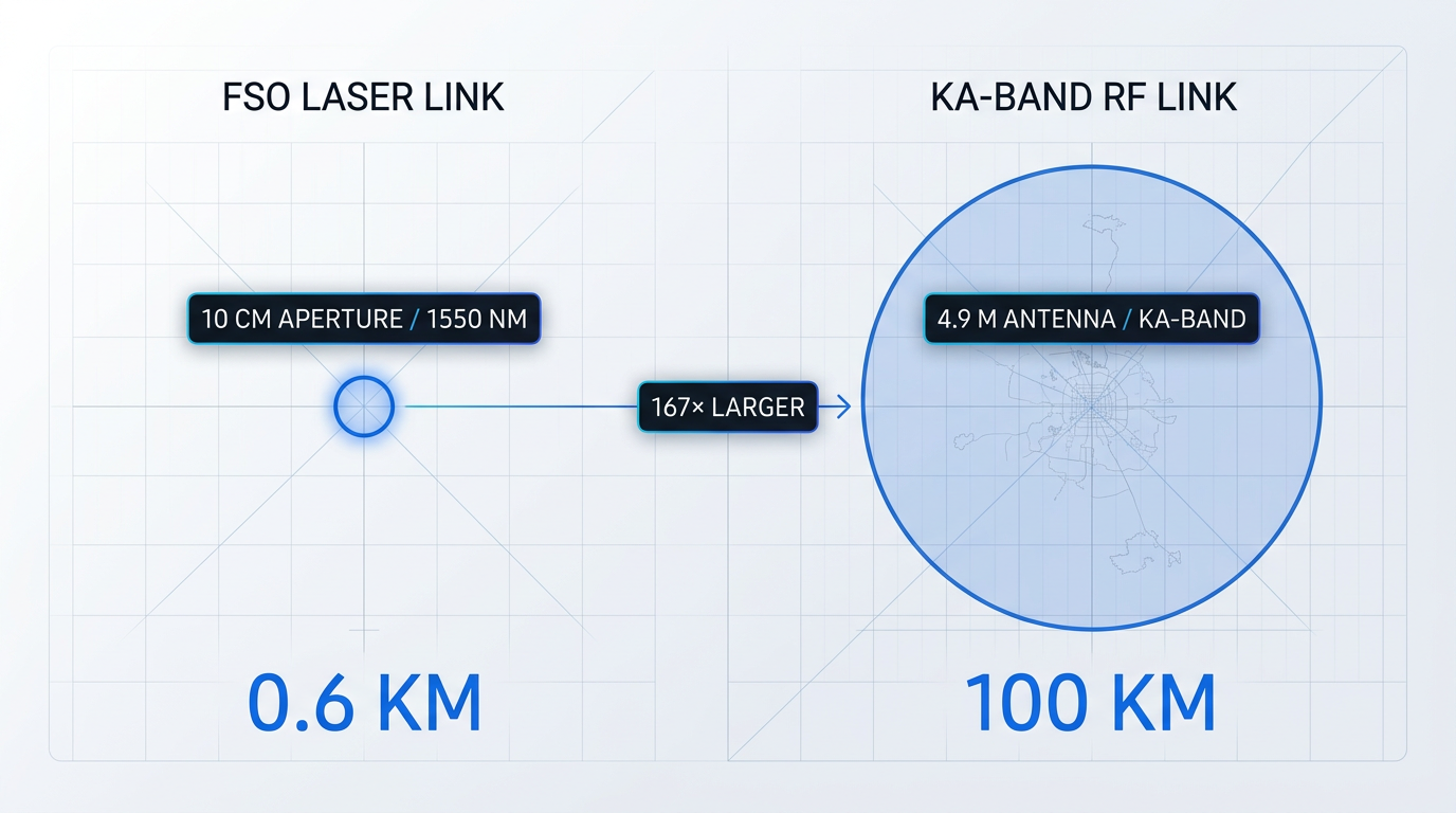
The practical consequence is that intercepting an FSO link requires an adversary to be within that small footprint with appropriate receiving equipment — a far more demanding physical requirement than intercepting an RF transmission that illuminates an area the size of a country.
A 10 cm optical aperture at 1550 nm from GEO produces a beam spot of roughly 0.6 km at the ground. A Ka-band RF terminal produces a spot of approximately 100 km — an area more than 27,000 times larger. That difference is the geometric basis of FSO's low probability of intercept.
This geometry underpins the low probability of intercept (LPI) and low probability of detection (LPD) characteristics that defence users cite as operationally significant. The narrow beam also reduces a platform's electromagnetic signature: unlike an RF antenna, a laser terminal does not broadcast its presence across a wide area.
Jamming is also structurally difficult: an adversary would need to direct a laser at the correct wavelength into the receiver's narrow field of view, which requires precise knowledge of the link geometry and physical proximity to the beam path.
The honest caveat is that physical link geometry reduces interception risk but does not eliminate it, and encryption remains recommended as an additional layer for any sensitive link. The narrow beam is a meaningful security advantage, not a substitute for cryptographic protection.
Where FSO Does Not Fit Well
The limitations section is where most FSO overviews go soft. This one does not. The constraints below are real, they are well-understood, and any programme manager evaluating FSO needs to account for them.
- Cloud cover: Cloud attenuation cannot be overcome by increasing transmit power. FSO ground links require cloud-free line of sight — this is an operational planning constraint, not a solvable link-budget problem.
- Pointing requirements: FSO pointing demands are far more stringent than RF. Platforms with limited attitude control capability or high vibration environments may not support FSO terminals without significant engineering investment.
- Radiation environment: Radiation-hardened fibres and qualified electronics are required for space operation, adding programme cost and schedule. DSOC and LCRD have demonstrated multi-year operation, but qualification remains a real programme-risk axis.
- Broadcast coverage mismatch: FSO is not suited to links where the receiver location is unknown or highly mobile. RF's wide beam is structurally better for broadcast and wide-area coverage scenarios.
- Ground-station infrastructure: The global RF ground-station network is mature and ubiquitous. The optical ground-station network is still developing, with far fewer sites and less geographic coverage today.
The cloud cover constraint deserves particular emphasis because it is the most operationally consequential. LCRD's own experiment data showed that optical ground station availability, factoring in weather, ran well below the near-100% availability of the co-located RF ground station — a concrete illustration of why cloud cover is a mission-design problem, not a marginal weather risk.
The ground-station infrastructure gap is real today but improving: NASA, ESA, JAXA, and DLR all operate dedicated optical ground stations, and commercial optical ground networks are now emerging. The constraint is a near-term operational reality, not a permanent structural barrier.
Hybrid RF/Optical: The Practical Engineering Answer
The operational response to FSO's limitations is not to abandon RF — it is to combine both technologies in architectures where each does what it does best. RF and FSO are complementary, not competing, and the most capable operational systems reflect that.
LCRD carries a Ka-band RF terminal precisely because cloud cover over an optical ground station creates link outages that RF can bridge. As NASA's LCRD documentation states directly: optical communications handle the high-volume data transfer where some latency is acceptable; RF provides high availability for real-time or low-latency requirements such as commanding, telemetry, and voice.
EDRS follows the same logic from the other direction: optical ISLs carry the high-rate LEO-to-GEO relay traffic, while Ka-band RF feeder links deliver the data from the GEO node to European ground stations — a hybrid architecture that achieves both the throughput of optical and the weather resilience of RF.
The distinction between mission types matters here. For a SmallSat direct-to-Earth downlink where cloud outages are operationally tolerable — because the data can wait for the next clear-sky pass — a pure FSO downlink is a viable and cost-effective choice. For a high-availability mission where continuous, low-latency service is required, hybrid is the practical answer.
The Artemis II O2O system operates alongside S-band RF, with both links running in parallel between the Orion spacecraft and ground — a pattern that will likely define crewed mission communications architecture for the foreseeable future.
With the application landscape and its real constraints now in view, the final dimension to understand is the regulatory and standardisation context that governs how FSO systems are licensed, coordinated, and made interoperable across agencies and operators.
Regulatory landscape: spectrum-free but not unregulated
One of the most frequently cited advantages of laser communications in space is freedom from spectrum licensing — no FCC filing, no ITU coordination, no queue for a frequency allocation. That freedom is real, but it does not mean FSO operates in a regulatory vacuum. The governance picture is more nuanced: optical frequencies are currently unregulated for interference coordination purposes, yet outdoor laser operations remain subject to a distinct set of safety oversight requirements that every programme must address.
Why optical frequencies are currently unregulated
In the radio frequency domain, the core purpose of licensing is to prevent interference between transmitters — a problem that arises because RF signals spread broadly and overlap. The ITU and national authorities such as the FCC and NTIA manage that risk through spectrum allocation and coordination procedures.
Lasercom interference is not currently coordinated by any equivalent regulatory body. As NASA's State of the Art Communications reports consistently note, two structural factors make such coordination unnecessary at present: laser beams are highly directional, with narrow divergence and a correspondingly small beam footprint at the receiver, making interference between independent links inherently unlikely; and the number of organisations operating laser communication systems remains small enough that a complex coordination body is not yet warranted.
That said, ITU World Radiocommunication Conferences have historically considered implementing regulation for optical communications — so the current absence of spectrum licensing for FSO reflects the conditions of today's deployment scale, not a permanent structural feature of the technology.
Outdoor laser safety: the regulatory dimension that remains
Where FSO does encounter regulatory oversight is in the domain of outdoor laser safety — a category entirely distinct from spectrum licensing. In the United States, three entities are concerned with aspects of outdoor laser operations for space programmes.
- FAA: Coordination is required when potentially harmful laser irradiance is transmitted through navigable airspace, covering both visible and non-visible beams above maximum permissible exposure thresholds.
- DoD Laser Clearing House: Relevant for DoD and DoD-sponsored missions; works to ensure outdoor laser use does not impact orbiting spacecraft or their sensors, including foreign assets.
- NASA Laser Safety Review Board: Focused on personnel safety for all NASA outdoor laser operations; missions submit safety documentation for LSRB review before launch, with FAA concurrence verified.
The FAA coordination requirement applies specifically to ground uplink operations, where high-power beams directed skyward pass through navigable airspace. The DoD Laser Clearing House engages early in the mission planning cycle for DoD programmes — the coordination process can take many months and should be initiated well ahead of operations.
Standardisation: CCSDS and the emerging framework
On the standardisation side, the Consultative Committee for Space Data Systems (CCSDS) is the primary international body working to establish interoperability frameworks for space optical communications. Its Optical Communications Working Group (SLS-OPT) operates under the Space Link Services area, with NASA and ESA participation — chaired from NASA's Jet Propulsion Laboratory, with ESA's ESOC holding the deputy chair.
The working group has an initial draft Pink Book (CCSDS 141.0-P-1.1) in process, with the stated goal of facilitating interoperability and cross-support between different optical communications systems. Both policy and regulatory approaches are described by NASA's SOA documents as still evolving — the CCSDS effort represents the leading multilateral attempt to create a common foundation.
The SDA OISL Standard: the most concrete design reference
The most concrete published standard currently shaping space lasercom terminal design is the SDA OISL Standard. Version 2.1.2 specifies the interoperability requirements for the Space Development Agency's Tranche 0 constellation, defining the physical and data link layer interface for space-to-space and space-to-ground optical links.
The OISL Standard v2.1.2 specifies that terminals operate in the optical C-band, support data rates between 100 Mbps and 1 Gbps, and use OOK-NRZ (On-Off Keying Non-Return-to-Zero) modulation. Link margin requirements are defined by range: space-to-space links beyond 5,000 km require 1 dB margin, while links up to 5,000 km and space-to-ground links up to 2,800 km require 3 dB margin.
The SDA has since released its Optical Communications Terminal (OCT) Standard Version 4.0.0 (28 June 2024) as the current iteration. NASA's State of the Art Communications reports describe the OCT Standard as a widely used design reference for space lasercom terminals across the sector — its influence extends well beyond SDA procurement into commercial and government terminal development more broadly.
Cross-constellation interoperability: a growing programme risk
As FSO capabilities proliferate across commercial constellations, government programmes, and scientific relay networks, a structural interoperability problem is emerging. Terminals built to one standard — whether SDA OISL, a proprietary commercial waveform, or a future CCSDS recommendation — cannot necessarily cross-talk with terminals built to another.
DARPA's Space-BACN (Space-Based Adaptive Communications Node) programme is the most direct response to this challenge. Its stated goal, per DARPA, is to create a reconfigurable, multi-protocol optical intersatellite communications terminal capable of connecting heterogeneous constellations that operate on different OISL specifications and would otherwise be unable to communicate.
Space-BACN moved into Phase 2 in late 2023, with DARPA down-selecting seven contractors from eleven. The programme's Technical Area 2 — designing a reconfigurable modem capable of supporting multiple optical waveforms up to 100 Gbps on a single wavelength — is the technical core of the interoperability solution, with Intel Federal and Arizona State University among the Phase 2 awardees for that work.
As commercial constellations, SDA programmes, and NASA relay networks each develop FSO capabilities to different standards, a terminal built to one specification cannot necessarily communicate with one built to another. DARPA's Space-BACN programme exists specifically because this fragmentation is already a real operational problem — not a theoretical future concern.
The interoperability challenge Space-BACN addresses at the space segment applies equally to ground infrastructure. Programme managers evaluating ground-station hardware should assess how a given system handles the coexistence of multiple optical link standards — the fragmentation DARPA is working to solve in orbit is already present in the broader ecosystem.
Watching the regulatory trajectory
The current absence of spectrum regulation for optical frequencies rests on two conditions: the small number of operators, and the highly directional nature of laser beams. Both conditions are changing as commercial constellations and proliferated government architectures scale FSO deployment significantly.
ITU World Radiocommunication Conferences have already considered implementing regulation for laser communications — a signal that the governance community is watching the technology's growth. The regulatory posture that applies at the start of a programme today may not be the one in place at programme completion or during its operational life.
With the regulatory and standards landscape mapped, the guide's closing section draws together the technology's current state and the trajectory the field is taking.
Conclusion
The state of laser communications in space
Laser communications in space has crossed the threshold that matters: the question is no longer whether it works, but how to deploy it reliably and at scale.
Cloud cover, PAT complexity, and an immature ground-station network remain the real constraints on adoption, which is why hybrid RF/optical architectures are the practical answer for most programmes today.
The ground segment is where the next chapter is being written — and the investment, the standards work, and the engineering effort are all pointing in the same direction.
Frequently asked questions about laser communications in space
Common questions about how free-space optical links work in practice, what their limitations are, and who is building them.
Interception is geometrically very difficult. A laser beam from GEO with a 10 cm aperture at 1550 nm produces a spot of roughly 0.6 km diameter at the receiver — compared with around 100 km for a Ka-band RF beam. An adversary must be physically within that small footprint with appropriate receiving equipment, which is operationally very hard to arrange. Jamming is equally challenging: it requires directing a laser at exactly the right wavelength into the receiver's narrow field of view, a task made harder when both transmitter and receiver are moving at orbital velocity. These characteristics are formally described as low probability of intercept (LPI) and low probability of detection (LPD). That said, the narrow beam makes interception geometrically difficult, not impossible. Encryption remains the recommended additional layer — physical link security does not replace cryptographic security, and operational practice treats both as complementary.
The hardest operational constraint is cloud cover. Unlike RF rain fade, cloud attenuation of an optical link cannot be overcome by increasing transmit power — the link simply requires a cloud-free line of sight (CFLOS). This is a planning problem, not an engineering one, and it is the reason optical ground stations are sited in areas with low cloud frequency. Pointing requirements are far more demanding than RF: the same narrow beam divergence that delivers security and bandwidth advantages means the acceptable pointing error is tiny, and not all spacecraft platforms can meet it. The global optical ground-station network is also still maturing — the RF infrastructure built up over decades is ubiquitous in a way that optical equivalents are not yet. Finally, qualifying components for the space radiation environment adds programme cost and schedule. For missions requiring high availability, hybrid RF/optical architectures are the practical near-term answer: RF handles backup links and low-rate telemetry while FSO carries the high-rate payload data.
The fundamental difference is the medium. Fibre-optic communication confines light within a glass waveguide, so the signal travels a guided path with no beam divergence, no pointing requirement, and no exposure to atmospheric effects. Free-space optical (FSO) communication propagates the beam through open space — vacuum or atmosphere — with no physical medium to guide it. As the beam travels, it spreads (beam divergence), the transmitter must aim precisely at the receiver (pointing loss), and ground links are subject to turbulence, scintillation, and cloud cover — none of which affect a fibre link. Despite this fundamental difference, the two technologies share a component supply chain. Both operate at 1550 nm (near-infrared C-band) and draw on the same erbium-doped fibre amplifiers (EDFAs), modulators, and photodetectors developed for the fibre-telecom industry. That shared base is a key reason 1550 nm was adopted for space FSO: decades of fibre-telecom investment had already driven down component costs and driven up reliability at this wavelength, making mature, proven hardware available for space applications.
Longevity depends heavily on orbit and component type. Erbium-doped fibres experience gain degradation under accumulated radiation dose — a known failure mode in the space radiation environment. Exail's radiation-hardened erbium-doped fibres, for example, are characterised to gain degradation of less than 0.25 dB per 100 krad in a 30 dB gain EDFA configuration. Pump diode lasers, which drive the amplification process in EDFAs, also degrade over time under radiation exposure. To address these effects, space-qualified components use radiation-hardened (rad-hard) fibres and pre-screened electronics specifically selected to limit degradation over the mission lifetime. The radiation environment varies significantly by orbit: LEO imposes relatively modest dose rates, GEO accumulates dose more slowly but over longer durations, and MEO — particularly within the Van Allen belts — presents the most challenging particle flux of all three regimes. Component qualification is therefore orbit-specific, and programmes targeting MEO or GEO face more stringent radiation testing requirements than those in LEO.
The ecosystem spans both commercial operators and research institutions. SpaceX has equipped its Starlink constellation with laser inter-satellite crosslinks, enabling satellite-to-satellite communication without relying on ground stations at every hop. Amazon's Project Kuiper successfully tested optical inter-satellite links between its two prototype satellites at 100 Gbps across distances of nearly 1,000 km. Telesat has designed its Lightspeed constellation with four 10 Gbps optical inter-satellite links per satellite, forming a global mesh network. On the terminal side, Tesat-Spacecom developed the laser communication terminals at the heart of ESA's European Data Relay System (EDRS), which relays data from LEO satellites to the ground via GEO nodes. MIT Lincoln Laboratory has been central to NASA's lasercom programme, developing terminals for LLCD, LCRD, ILLUMA-T, TBIRD, and the forthcoming O2O mission on Orion. NASA's Jet Propulsion Laboratory managed the Deep Space Optical Communications (DSOC) experiment aboard the Psyche spacecraft, receiving signals at the Hale Telescope at Palomar Observatory. This is not an exhaustive survey — the commercial ecosystem is growing rapidly and new entrants are active across terminals, ground stations, and network services.