

Introduction
Free space optical communications is a technology with genuine depth — and most overviews barely scratch the surface.
This guide covers the full picture: how FSO systems are built and operated, where they are deployed across contexts ranging from urban rooftop links to orbital constellations, the real-world challenges that affect link performance, and the engineering approaches used to address them.
It is written for engineers, researchers, and procurement professionals who want a grounded understanding of FSO as a technology domain — not a product brochure, but a resource worth reading carefully.
TL;DR
FSO is a mature, high-performance wireless technology with a well-understood engineering profile — and its challenges are far more tractable than they first appear. Readers who finish this guide will be equipped to evaluate FSO honestly: knowing where it excels, where it demands careful design, and how practitioners actually make it work reliably across a wide range of environments.
This article covers:

How FSO systems work: components and modulation
FSO vs. RF and fibre: where each fits
FSO application domains: terrestrial to inter-satellite
Atmospheric challenges affecting FSO link performance
Mitigation techniques and hybrid FSO/RF architectures
FSO security in contested spectrum environments
What is free space optical communication?
Imagine transmitting gigabits of data between two points using nothing but a beam of light through open air — no cable, no radio licence, no physical infrastructure between the terminals. That is the core premise of free space optical (FSO) communication: a wireless data transmission technology that uses modulated light beams, typically lasers, propagating through free space rather than through optical fibre or radio frequency channels.
FSO is a line-of-sight technology. The transmitter and receiver must have an unobstructed optical path between them, with the atmosphere or the vacuum of space serving as the propagation medium — not a waveguide, not a cable, but open space itself.
At the conceptual level, an FSO system is straightforward: one terminal converts data into modulated optical pulses and projects them through a lens or telescope toward a distant receiver; the receiver captures the arriving light and converts it back into an electrical signal. Two terminals, pointed at each other, with a beam of light between them. The engineering to make that work reliably is where the depth lies.
FSO versus fibre and RF
The clearest way to understand FSO is to position it against the two technologies it most closely resembles. Compared to fibre optic communication, FSO uses the same optical carrier wavelengths and shares many of the same underlying components — laser sources, photodetectors, optical modulators. The fundamental difference is the transmission medium: glass waveguide versus open space. FSO requires no trenching, no right-of-way permits, no physical connection between endpoints. It is, as the field often describes it, fibre without the fibre.
The contrast with radio frequency (RF) wireless is different in character. FSO operates at optical carrier frequencies — hundreds of terahertz — compared to the gigahertz range of RF systems, a difference of several orders of magnitude. That gap in carrier frequency translates directly into bandwidth potential: optical carriers support far higher data rates than RF. FSO beams are also highly directional, diverging at milliradians rather than the broad lobes of RF antennas. And where RF spectrum requires coordinated licensing, FSO operates in unlicensed optical spectrum — no regulatory coordination required.
These distinctions from both fibre and RF converge on three characteristics that define FSO as a technology class.
- Licence-free operation: FSO uses optical spectrum not subject to RF regulation, eliminating spectrum licensing fees and coordination delays entirely.
- High data rate potential: FSO links have demonstrated Gbps to Tbps-class throughput; even beyond 10 km, transmission rates exceeding 1.72 Tbps have been achieved.
- Narrow beam divergence: FSO beams diverge at milliradians, giving inherently high directivity and spatial selectivity that RF systems cannot match.
Together, these three characteristics explain why FSO occupies a distinct niche: it delivers fibre-class bandwidth without fibre infrastructure, and wireless deployment flexibility without the spectrum congestion and licensing burden of RF. No other technology class combines all three.
A brief history of FSO
The idea of transmitting information on a beam of light predates the laser by eighty years. In 1880, Alexander Graham Bell patented the photophone — a device that modulated sunlight with a vibrating mirror to carry voice over a distance of 213 metres. Bell regarded it as one of his greatest inventions. The photophone demonstrated the conceptual possibility of optical wireless communication, but without a coherent, controllable light source it could not become a practical technology. It remained an intellectual ancestor rather than a direct precursor.
- Laser invention and early experiments (1960s): The laser's 1960 invention immediately opened atmospheric optical transmission as an active research field; early free-space link demonstrations followed within months.
- ESA SILEX programme (1985–2001): ESA's Semiconductor-laser Intersatellite Link Experiment achieved the first civilian optical link between two spacecraft, transmitting at 50 Mbps between SPOT-4 and Artemis.
- NASA LLCD (2013): The Lunar Laser Communication Demonstration transmitted 622 Mbps from lunar orbit — more than six times faster than the best comparable RF system, from 400,000 km.
- Commercial satellite ISLs (2019–present): Starlink, Amazon Kuiper, and Telesat Lightspeed have deployed optical inter-satellite links at scale, with Starlink alone reporting more than 10,000 laser terminals in orbit.
What this arc reveals is a technology that has moved decisively from laboratory curiosity to operational infrastructure. FSO is not experimental — it has proven deployments across terrestrial, aerial, and space domains. But it is also not a fully solved engineering problem: standardisation bodies including the Space Development Agency (SDA) and CCSDS remain active, pointing and tracking at scale continues to be refined, and the atmosphere's effect on link reliability is an ongoing area of engineering development.
Bell demonstrated optical wireless communication in 1880 using sunlight. Today, more than 10,000 laser terminals operate in commercial satellite constellations. FSO has deep roots and accelerating deployment — a rare combination in any engineering discipline.
With FSO defined and contextualised, the logical next step is understanding how a system is actually built — the transmitter optics, the propagation channel, and the receiver that together make a link work.
How FSO Systems Work: Components and Modulation
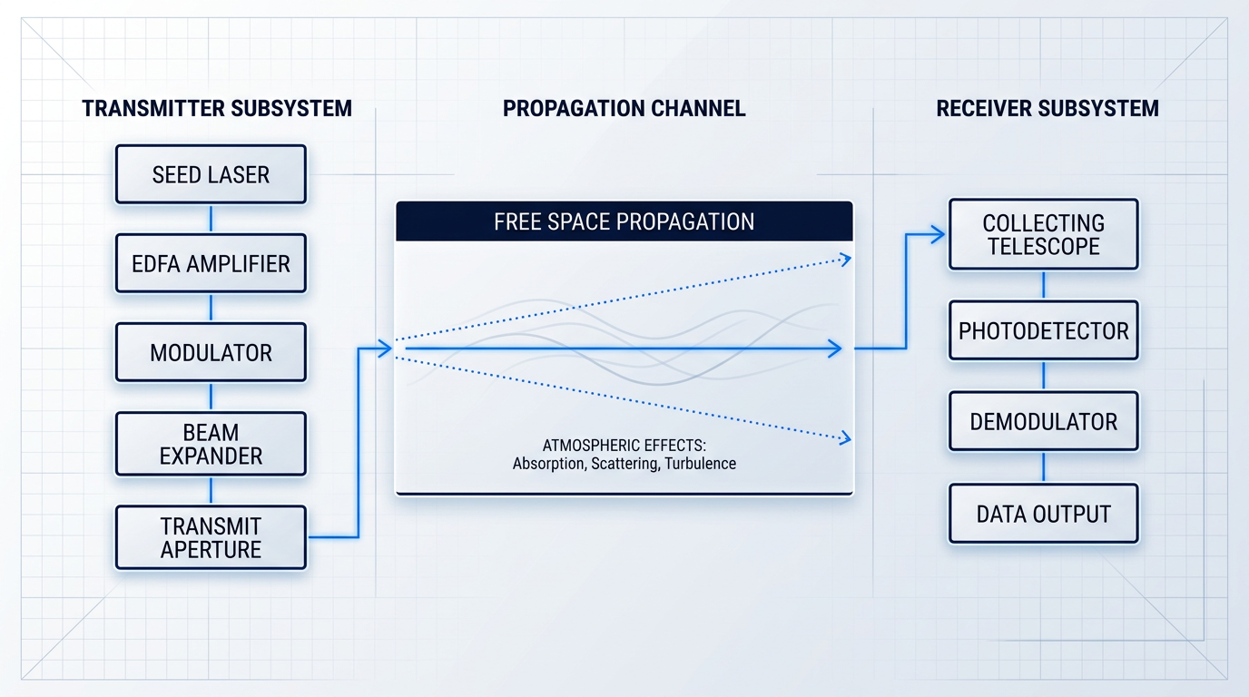
Every free space optical communication link, whether it spans two rooftops or bridges a satellite to the ground, follows the same fundamental signal chain: a transmitter that encodes data onto a light beam, a propagation channel through open air or vacuum, and a receiver that recovers the data at the far end. Understanding each stage — and the engineering choices made within it — is the foundation for everything that follows in this guide.
The Transmitter Subsystem
The transmitter begins with a laser source, most commonly a semiconductor laser diode, which generates a coherent, narrow-linewidth optical carrier at the chosen operating wavelength.
For high-power links — long-range terrestrial connections and satellite uplinks in particular — a semiconductor diode alone rarely delivers sufficient output power. An erbium-doped fibre amplifier (EDFA) is added as the power amplification stage, boosting the output of a low-power seed laser to the watt-level powers needed to close the link budget over distance.
Between the laser source and the amplifier sits the modulator, which encodes the data stream onto the optical carrier — either by varying the intensity of the beam or, in more sophisticated systems, by manipulating its phase. The modulation approach chosen here determines the complexity of both the transmitter and the receiver.
The final transmitter element is the beam expander (or transmit telescope), which collimates and expands the beam before it enters the propagation channel. A wider beam diverges less over distance, concentrating more power onto the receiver aperture — but the trade-off is real: a narrower divergence angle demands tighter pointing accuracy, which has direct consequences for the alignment system.
The Propagation Channel and PAT
Unlike fibre, the propagation channel in an FSO link is unguided: the beam travels through open air or vacuum with no physical medium to contain or direct it.
When the channel is the atmosphere, it introduces impairments — absorption, scattering, turbulence-induced intensity fluctuations — that can degrade or interrupt the link. The nature and severity of those impairments is covered in detail later in this guide; for now, the key point is that the atmosphere is not a neutral medium, and FSO system design must account for it.
The narrow beam that makes FSO spectrally efficient and inherently secure also creates a precise alignment requirement. This is the engineering discipline of pointing, acquisition, and tracking (PAT), and it is one of the defining challenges of FSO system design.
- Acquisition: The initial phase: each terminal searches its uncertainty region to locate the other terminal's beam before a link can be established.
- Pointing: Once acquired, the transmitter directs its beam precisely toward the receiver aperture, accounting for geometry and any known platform motion.
- Tracking: The ongoing phase: active feedback systems maintain alignment dynamically, correcting for vibration, thermal drift, or platform movement in real time.
PAT complexity scales sharply with platform mobility. A building-to-building terrestrial link is largely a solved problem — both terminals are fixed, and pointing errors arise mainly from thermal expansion and wind-induced vibration. A satellite-to-ground link or UAV-mounted terminal introduces relative motion at high angular rates, requiring fast-steering mirrors and closed-loop tracking systems that operate on millisecond timescales.
The Receiver Subsystem
At the far end of the link, a collecting telescope gathers the incoming beam. Aperture diameter is a primary design parameter: a larger aperture intercepts more of the beam's optical power, which directly improves the received signal-to-noise ratio and extends usable range.
Behind the telescope, a photodetector converts the incoming optical power into an electrical signal. Two detector types dominate FSO receivers.
- PIN photodiodes: Simpler construction, lower cost, no internal gain. Well-suited to shorter links or high-power received signals where sensitivity is less critical.
- Avalanche photodiodes (APDs): Provide internal multiplication gain, yielding better sensitivity at low received power levels. Preferred for long-range links, but more temperature-sensitive and complex to bias correctly.
The choice between a PIN diode and an APD is fundamentally a sensitivity-versus-complexity trade-off: APDs recover weaker signals but require tighter thermal management and more careful operating point control, which adds cost and design overhead.
A demodulator completes the receiver chain, recovering the data from the electrical signal. Its architecture must match the modulation scheme used at the transmitter — which makes the choice of modulation a system-level decision that shapes both ends of the link.
Modulation Schemes: Intensity and Coherent
The dominant architecture in commercial FSO is intensity modulation with direct detection (IM/DD): the transmitter varies the beam's optical power to encode data, and the receiver simply measures that power — no phase reference required. IM/DD is straightforward to implement and cost-effective, which explains its prevalence in terrestrial links.
Within IM/DD, On-Off Keying (OOK) is the simplest modulation scheme: the laser is switched on for a binary '1' and off for a '0'. OOK's appeal is its minimal implementation complexity, but it has two meaningful limitations — it is vulnerable to intensity fluctuations caused by atmospheric turbulence (scintillation), and its spectral efficiency is modest compared to phase-based alternatives.
Pulse Position Modulation (PPM) encodes data in the timing of a pulse rather than its presence or absence. This makes PPM significantly more photon-efficient than OOK, which is why it is the preferred scheme for power-constrained links such as deep-space optical communications. The cost is bandwidth efficiency and synchronisation complexity — PPM requires precise timing recovery at the receiver.
Where link margin is tight and spectral efficiency matters, coherent detection offers a step change in performance. In coherent systems, a local oscillator laser at the receiver mixes with the incoming signal, enabling recovery of both phase and amplitude. Schemes such as DPSK (Differential Phase Shift Keying) and its quadrature variant DQPSK encode data in phase transitions rather than intensity, providing better receiver sensitivity and greater resilience to intensity fluctuations than OOK.
Homodyne and heterodyne coherent receivers push sensitivity and spectral efficiency to their practical limits, making them the preferred approach for long-distance terrestrial links and inter-satellite optical links where every decibel of link margin is valuable. The trade-off is hardware complexity: coherent receivers require tight wavelength control and a stable local oscillator, which adds cost and engineering overhead.
The right modulation choice is always a function of the link requirements. OOK and IM/DD suit short-to-medium terrestrial links where simplicity and cost dominate; coherent schemes suit high-throughput, long-range, or space links where sensitivity and spectral efficiency are worth the added complexity. Neither is universally superior.
Wavelength Selection: 850 nm vs. 1550 nm
Commercial FSO systems operate primarily in two wavelength bands: 850 nm and 1550 nm. The 850 nm band was the early commercial standard, largely because silicon photodetectors are sensitive at this wavelength and the associated components are less expensive. For short-range, lower-power links, it remains a viable choice.
For high-performance links, however, 1550 nm has become the operationally mature choice, and the reasons go beyond a single specification.
The most cited advantage is eye safety. At 1550 nm, the cornea and lens absorb the radiation before it reaches the retina, whereas 850 nm light (near-infrared) can be focused by the eye's optics directly onto the retina. This difference in physiology means that 1550 nm systems operate under a higher maximum permissible exposure (MPE) limit, allowing them to transmit more optical power within regulatory eye-safety bounds — which translates directly into longer range or improved link margin.
The 1550 nm band also sits within an atmospheric transmission window where absorption by water vapour and other atmospheric gases is comparatively low, supporting efficient propagation through the troposphere.
Choosing 1550 nm for an FSO link means inheriting the full C-band and L-band fibre-optic infrastructure — EDFAs, components, test equipment, connectors, and supply chains — built up over decades of telecom investment. That ecosystem maturity is a more durable advantage than eye-safety margins alone.
The amplification ecosystem is the third and most consequential advantage. The global fibre-optic telecommunications industry built its entire C-band and L-band infrastructure around 1550 nm: EDFAs, wavelength-division multiplexing components, precision test equipment, low-loss connectors, and mature supply chains all exist because this wavelength underpins long-haul fibre networks worldwide. An FSO system operating at 1550 nm inherits that depth of component maturity and amplification capability in a way that an 850 nm system simply cannot.
As a publisher specialising in 1550 nm fibre amplification, Woodrow Scientific's perspective is that the ecosystem advantage is the argument most worth making explicitly — because it is the one most likely to be underweighted by engineers who focus only on the eye-safety specification.
In practice, the EDFA is the component that makes this ecosystem advantage tangible at the transmitter. For satellite uplink applications, Woodrow Scientific Limited's EDF-UL-10 series is a concrete example of what a purpose-built 1550 nm uplink amplifier looks like: a UK-designed and manufactured EDFA delivering 10 W at high beam quality, with the tracking beacon and uplink data nested in a single amplified beam — a configuration that, as far as WSL is aware, no other supplier currently offers. Built on patented technology with engineering roots in Southampton's Optoelectronics Research Centre (the birthplace of the EDFA), and configured to each ground station across both hardware and software layers via WSL's Modulation-on-Demand platform, it illustrates the operational depth that an in-house manufacturer can bring compared with catalogue resellers. CE and UKCA certified.
With the signal chain, modulation landscape, and wavelength rationale established, the natural next question is how FSO's design choices — its optical carrier, narrow beam, and licence-free spectrum — position it against RF and fibre optic communications in real-world deployment decisions.
FSO vs. RF and Fibre: Where Each Technology Fits
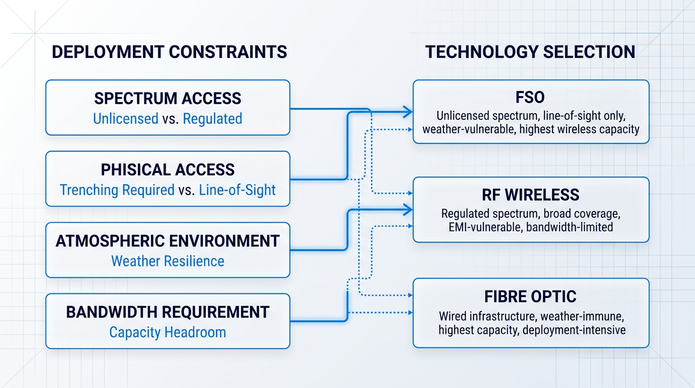
Understanding what FSO is and how it works is only half the picture. The more consequential question for any engineer or procurement professional is: given the alternatives, when is FSO the right choice? The answer depends less on abstract performance metrics and more on the specific constraints of a deployment — spectrum availability, physical access, atmospheric environment, and security requirements. Mapping those constraints against the properties of FSO, RF, and fibre is what makes the technology selection decision tractable.
FSO vs. RF Wireless
The most fundamental difference between FSO and RF lies in the carrier frequency. Optical carriers operate at frequencies far higher than RF, and because available bandwidth scales with carrier frequency, FSO links can support data throughput that current RF systems cannot approach — placing FSO among the highest-capacity wireless technologies available.
This RF bandwidth ceiling is not an abstract disadvantage: it is an active engineering pressure in the satellite industry, where growing demand for high-throughput feeder links between ground stations and satellites is straining the capacity of conventional RF bands. FSO's substantial capacity headroom makes it a structurally compelling candidate for those links.
On the regulatory dimension, FSO operates in unlicensed optical spectrum. There is no frequency coordination process, no regulatory filing, and no licensing cost. For RF, spectrum access requires coordination with national regulators, is subject to congestion in commercially valuable bands, and in defence and satellite contexts represents a strategic constraint: the ability to operate on a given frequency can be denied, contested, or simply unavailable in a given theatre or orbital slot.
The beam geometry of FSO also differs fundamentally from RF. Whereas RF antennas radiate energy across broad lobes, an FSO transmitter produces a tightly collimated beam with very low angular divergence, meaning energy is confined to a narrow corridor between the two terminals. There are no detectable electromagnetic emissions outside that path, which has direct implications for intercept resistance and covertness. This property is examined in depth in the security section of this guide; here it is sufficient to note it as a structural advantage over RF in contested environments.
The one dimension where RF holds a clear advantage over FSO is atmospheric resilience. RF signals propagate through fog, cloud, and precipitation with comparatively little degradation, while FSO links can be significantly attenuated by dense fog or heavy rain. The physics of that vulnerability are covered in the atmospheric challenges section; what matters here is the strategic implication.
FSO, for its part, is not susceptible to electromagnetic interference in the way RF is: an optical link operating in the infrared spectrum cannot be disrupted by conventional RF jamming or radar emissions. These are genuinely complementary failure modes — FSO degrades in weather conditions that leave RF unaffected, while RF is vulnerable to interference conditions that FSO does not share.
FSO degrades in atmospheric conditions that leave RF unaffected; RF is vulnerable to electromagnetic interference that FSO does not experience. Because their failure modes do not overlap, the two media are natural partners in high-availability system design — each covering the other's weakness.
This complementarity is the core rationale for hybrid FSO/RF systems, where both links run in parallel and traffic is routed between them depending on prevailing conditions. The engineering architecture for those hybrid designs is covered later in this guide.
FSO vs. Fibre Optic Communications
Fibre and FSO share the same physical medium — light — but differ entirely in how that light is guided. Fibre confines the beam within a glass strand; FSO propagates it through open air or vacuum. That single difference drives almost every practical trade-off between them.
Fibre's capacity is, for practical purposes, very large and continues to expand with advances in wavelength-division multiplexing. It is also completely unaffected by atmospheric conditions. For permanent, high-availability backbone infrastructure — data centre interconnects, metropolitan core networks, transoceanic links — fibre is the correct engineering answer, and no honest comparison should suggest otherwise.
Where fibre loses its advantage is deployment. Installing fibre in a dense urban environment requires trenching, right-of-way permits, regulatory approvals, and civil engineering work that can be a lengthy and costly process — often substantially more expensive per kilometre than an equivalent FSO deployment, particularly where no existing duct infrastructure is available.
FSO, by contrast, requires only a clear line-of-sight path and mounting points at each terminal. Deployment is significantly faster than cabled alternatives, with no civil works, no permits for underground access, and no disruption to the surrounding environment — making it well suited to scenarios where speed of activation matters.
The capacity of an FSO link over short distances is competitive with current fibre speeds, so the trade-off is not primarily about throughput — it is about the atmospheric dependency that fibre does not share. For last-mile connectivity where trenching is economically impractical, or for temporary high-capacity links where speed of deployment outweighs long-term availability guarantees, FSO fills a gap that fibre cannot.
Where FSO Is the Right Choice
The comparison across both axes resolves into a set of concrete deployment scenarios where FSO's specific properties make it the appropriate technology choice.
- Urban last-mile links: Where fibre trenching is economically or physically impractical, FSO bridges the gap between a fibre point-of-presence and a building rooftop without civil works.
- Disaster recovery: When infrastructure is destroyed or unavailable, FSO links can be deployed rapidly to restore high-capacity communications without any fixed infrastructure.
- Inter-satellite optical links: In space, fibre is physically impossible and RF bandwidth is limited; FSO is a well-established medium for high-throughput data relay across space segments.
- Defence tactical communications: In RF-denied or RF-congested environments, FSO's unlicensed spectrum and narrow beam provide covert, interference-resistant links that RF cannot reliably offer.
- Satellite feeder link augmentation: As demand for high-throughput ground-to-satellite links outpaces RF capacity, FSO provides the bandwidth headroom that congested RF bands cannot deliver.
In each of these scenarios, FSO is not a compromise — it is the technology that fits the constraints. Fibre remains superior for permanent backbone infrastructure, RF remains more resilient in adverse weather, and FSO is the right answer precisely where those alternatives are unavailable, impractical, or insufficient.
With this evaluative framework in place, the application domains that follow — terrestrial, aerial, maritime, and space — become much easier to interpret: in each case, one or more of these deployment conditions is present, and FSO's selection follows directly from the trade-off logic set out here.
FSO application domains: terrestrial, aerial, maritime, and space
Few wireless technologies operate across as wide a range of environments as free space optical communications — from rooftop-to-rooftop links spanning a few hundred metres in a city centre, to laser crosslinks between satellites separated by thousands of kilometres in orbit.
Each deployment environment presents its own operational logic and engineering constraints, which is why surveying FSO's application domains is more than a catalogue exercise: it shows how the same underlying technology adapts to radically different contexts, and why no single domain captures the full picture of what FSO enables.
Terrestrial last-mile and building-to-building links
Terrestrial FSO is the technology's original commercial application, addressing a problem that fibre cannot solve economically: connecting buildings separated by hundreds of metres to a few kilometres when trenching is physically impractical or cost-prohibitive.
Dense urban environments present the clearest case — a heritage building where civil works are prohibited, a river crossing where duct installation is prohibitively expensive, or a campus where two structures are separated by a road that cannot be disturbed.
Beyond permanent infrastructure, terrestrial FSO suits temporary deployments well: broadcast and event connectivity, disaster recovery links when physical infrastructure has been damaged, and emergency communications where speed of deployment matters more than long-term cost.
The licence-free, no-spectrum-footprint nature of FSO makes it particularly attractive for urban backhaul — a network operator can install a point-to-point link between two buildings without regulatory delay, achieving throughput that would otherwise require a fibre pull.
Aerial platforms: UAVs and high-altitude stations
Unmanned aerial vehicles (UAVs) have become an important FSO relay platform, particularly in tactical and surveillance contexts where a UAV acts as an airborne relay node, passing high-bandwidth sensor or video data to a ground station or across to another platform.
High-altitude platform stations (HAPs) — stratospheric aircraft or balloons operating above the bulk of the weather — take this concept further, functioning as persistent relay nodes positioned between ground infrastructure and satellite systems.
The defining engineering constraint for aerial FSO is pointing, acquisition, and tracking (PAT): because the platform is continuously in motion, optical terminals must maintain precise beam alignment dynamically, rather than relying on the fixed mounting geometry that simplifies terrestrial installations.
Operationally, aerial FSO is attractive because platforms can be repositioned rapidly, provide line-of-sight coverage over large areas, and — in the case of HAPs — operate above most atmospheric disturbance, reducing the weather-related impairments that affect ground-level links.
Maritime FSO communications
Ship-to-ship and ship-to-shore FSO links face a combination of challenges that make the marine environment one of the more demanding deployment contexts: sea spray and salt aerosol introduce scattering losses, near-horizon link geometry increases the effective atmospheric path length, and platform motion — pitch, roll, and yaw — creates continuous pointing perturbations.
Despite these challenges, FSO offers something RF cannot easily provide at sea: high-throughput, low-intercept connectivity that does not consume scarce radio-frequency bandwidth allocations.
In the maritime context, FSO is best understood as a supplement to RF rather than a replacement — used selectively for high-bandwidth transfers or security-sensitive links where the directional nature of the optical beam is operationally valuable.
Inter-satellite optical links (ISLs)
Inter-satellite optical links (ISLs) represent the fastest-growing FSO application domain, and arguably the one with the greatest structural significance for how global communications networks are architected.
By connecting satellites directly to one another with laser crosslinks, ISLs eliminate the need for intermediate ground relay stations to route traffic across a constellation — data can travel from one point on Earth to another via an in-orbit optical mesh, reducing latency and increasing aggregate network throughput.
The propagation environment for ISLs is, in one critical respect, the most favourable of any FSO domain: links operate in vacuum, entirely free of the atmospheric impairments that dominate terrestrial and ground-to-space scenarios.
Specialist suppliers of optical inter-satellite terminals have developed commercial product lines serving satellite programme integrators, and ISL-equipped constellations have progressed well beyond laboratory demonstration into operational service — a transition that validates FSO at constellation scale as an engineering reality.
The primary engineering challenge for ISLs is PAT at orbital velocities across ranges that can extend to thousands of kilometres — maintaining sub-microradian pointing accuracy between two satellites moving at several kilometres per second demands highly capable onboard tracking systems.
Adding optical inter-satellite links to a LEO constellation changes the fundamental network architecture — from a ground-relay-dependent hub-and-spoke model to a distributed in-orbit mesh — altering latency, resilience, and routing in ways that incremental RF improvements cannot replicate.
Satellite-to-ground optical links
Where ISLs benefit from vacuum propagation, satellite-to-ground optical links face the opposite condition: the entire atmospheric column must be traversed on every uplink and downlink, making this the domain where atmospheric impairments are most consequential.
Cloud cover is the most operationally significant challenge, which is why site diversity networks — geographically distributed optical ground stations (OGS) — are the standard operational response, ensuring that at least one station in the network has a clear line of sight to the satellite at any given time.
NASA has been central to validating satellite-to-ground optical communications through a sequence of progressively ambitious demonstration missions, including the LLCD (Lunar Laser Communication Demonstration), the LCRD (Laser Communications Relay Demonstration), and ILLUMA-T (Integrated LCRD LEO User Modem and Amplifier Terminal).
These missions have collectively demonstrated that optical links can operate reliably across distances ranging from low Earth orbit to lunar range, establishing the performance and operational credibility needed for optical feeder links to be considered for next-generation satellite systems.
The capacity argument is straightforward: optical feeder links can deliver substantially greater downlink throughput than RF links of comparable mass and power, which is why next-generation high-throughput satellite systems are increasingly designed around optical ground-to-space interfaces.
Military and tactical FSO communications
Military interest in FSO is driven primarily by two characteristics: low probability of intercept and detection (LPI/LPD), and resistance to jamming — properties that make FSO operationally attractive in contested environments where RF links are either unavailable or actively compromised.
Tactical applications span ground-to-ground links in forward operating environments, air-to-ground data relay from airborne platforms, and cross-domain links in scenarios where the RF spectrum is congested or denied by an adversary.
FSO leaves no radio-frequency emissions footprint detectable outside the beam path and requires no spectrum licensing — two practical advantages that matter considerably in operational planning, independent of the underlying physics that make FSO inherently difficult to intercept.
The security properties underpinning these advantages — beam geometry, the physics of LPI/LPD, and the mechanics of jamming resistance — are examined in depth in the section on FSO security characteristics.
Each of these six domains faces a distinct atmospheric and environmental challenge profile: terrestrial links contend with low-level turbulence and fog, satellite-to-ground links must traverse the full atmospheric column, and ISLs operate in vacuum with essentially no atmospheric impairment — a spectrum of conditions that shapes system design in fundamentally different ways, and which the next section examines in detail.
Atmospheric and environmental challenges in FSO links
A free-space optical link is, at its core, an exercise in precision through an uncontrolled medium. The transmitter and receiver can be engineered to extraordinary tolerances, but the column of atmosphere between them cannot — it is shared with weather systems, thermal gradients, mechanical vibration, and a star that pumps broadband optical noise into the receiver's field of view. For terrestrial deployments of the kind surveyed earlier, and for the satellite-to-ground links where the beam must traverse the full atmospheric column, understanding these impairments is not academic: it is the central engineering problem.
Fog and precipitation attenuation
Fog is the dominant atmospheric impairment for terrestrial FSO links, and it is important to understand why it is so much more severe than other hydrometeors. The physical mechanism is Mie scattering: fog droplets have diameters in roughly the 0.5–15 µm range, which is comparable to the optical wavelengths used in FSO systems (typically 850 nm and 1,550 nm). When a scatterer's size is on the order of the wavelength, scattering efficiency is maximised — the beam is not simply absorbed but redirected away from the receiver aperture with very high probability per droplet encountered.
The practical consequence is attenuation of a severity that has no parallel among other atmospheric phenomena at optical wavelengths. Measurement campaigns under dense maritime fog conditions have recorded attenuation values reaching 480 dB/km, with continental fog events routinely producing values in the range of tens to over a hundred dB/km at visibilities below a few hundred metres. A Prague fog event measured concurrently at 850 nm and 1,550 nm recorded peak attenuations of approximately 155 dB/km and 111 dB/km respectively — figures that render even a short link unusable without substantial link margin.
For link availability planning, fog is effectively the binding constraint in most mid-latitude continental climates: the availability budget is essentially a fog budget, with rain, snow, and turbulence playing secondary roles that matter most at the margins. An important nuance is that in dense fog (visibility below roughly 500 m), attenuation becomes largely wavelength-independent across the FSO operating bands — the Kim model captures this explicitly, recognising that at very low visibilities, the droplet size distribution dominates and the wavelength dependence seen in clearer conditions largely disappears.
Rain is a significant impairment for longer terrestrial links but is considerably less severe than fog at optical wavelengths, and the physical reason is the same Mie scattering framework applied to larger particles. Rain droplets are typically 0.5–5 mm in diameter — three to four orders of magnitude larger than optical wavelengths — which means scattering efficiency per unit of liquid water content is far lower than for the fine droplets of fog. Rain-induced attenuation at FSO operating wavelengths is also largely wavelength-insensitive across the 850 nm to 1,550 nm range, which creates an important asymmetry: rain simultaneously attenuates millimetre-wave RF links (such as E-band at 70–80 GHz) far more severely than it does optical links, a complementary behaviour that has direct implications for system architecture — a point that the next section develops.
Snow presents a more variable picture than rain because its attenuation depends strongly on flake morphology. Wet snow — large, wet flakes with high liquid water content — produces significantly higher attenuation than dry snow, with heavy wet snowfall capable of approaching fog-like attenuation levels; the Kim visibility-based model can be used as a reasonable approximation for wet snow attenuation. Dry snow, composed of smaller, drier crystals with lower liquid water content, is a more moderate impairment, broadly comparable to moderate rain in terms of link margin impact.
Haze — caused by fine particulate matter and elevated humidity — is a persistent but rarely catastrophic impairment. It reduces link margin and raises the bit error rate, but unlike fog it does not typically cause complete link outages; visibility in haze remains above the threshold at which FSO links fail. In arid and semi-arid environments, dust and aerosol scattering play a comparable role: Mie extinction from suspended mineral particles degrades link margin and can, during severe dust events in regions such as the Middle East or North Africa, produce attenuation significant enough to threaten link availability on longer paths.
Atmospheric turbulence and scintillation
Atmospheric turbulence is the most physically complex impairment category in FSO link design. The mechanism begins with random fluctuations in atmospheric temperature and pressure — thermal turbulence — which produce corresponding fluctuations in the refractive index of air across a range of spatial scales. As the optical beam propagates through this inhomogeneous medium, different parts of the wavefront encounter slightly different refractive indices and travel at slightly different phase velocities, producing two distinct classes of degradation.
The first is intensity scintillation: the constructive and destructive interference of phase-distorted wavefront components causes the received optical power to fluctuate randomly around its mean value, producing fades that can temporarily drop the instantaneous SNR below the detection threshold even when the time-averaged power is adequate. The second is phase distortion: wavefront aberration degrades the performance of coherent detection receivers and makes coupling into single-mode fibre — required for coherent receivers and EDFA-based optical amplification — significantly more difficult, as efficient SMF coupling demands a near-diffraction-limited wavefront.
The standard measure of turbulence severity is the scintillation index (σ²_I), defined as the normalised variance of the received intensity fluctuations. The underlying turbulence strength is characterised by the refractive index structure parameter C²_n, which in natural atmospheres typically ranges from around 10⁻¹⁶ m⁻²/³ under weak turbulence conditions to 10⁻¹² m⁻²/³ or above under strong near-ground turbulence. For statistical modelling of the FSO channel under moderate-to-strong turbulence, the Gamma-Gamma distribution is the standard framework in the research literature: it models intensity fluctuations as the product of two independent Gamma-distributed processes representing large-scale and small-scale turbulent effects, and has been validated against both simulation and field measurement data across a range of link geometries.
Turbulence is particularly demanding for space-to-ground links, where the beam propagates through the full depth of the optically active atmosphere — roughly the lowest 10–20 km — accumulating turbulence effects that a short horizontal terrestrial link would not experience. On a satellite downlink, the beam arrives at the ground as an essentially plane wave that has integrated turbulence contributions along the entire slant path; the scintillation index for a downlink is well described by the Rytov variance integrated over the atmospheric column, and increases substantially at lower elevation angles as the slant path length through the atmosphere grows. An LEO-to-ground FSO link can experience power variation exceeding 10 dB from turbulence effects alone, compounding the propagation and scattering losses that also vary over an orbital pass.
For terrestrial FSO links, fog is the primary availability threat — attenuation of tens to hundreds of dB/km renders even short links unusable during dense fog events. Turbulence, by contrast, rarely causes outages on short terrestrial paths but becomes the dominant impairment for space-to-ground links, where the beam accumulates refractive index fluctuations across the full atmospheric column.
Beam wander and pointing errors
Beam wander is a distinct physical phenomenon from scintillation and must be treated separately in link analysis. Where scintillation is driven by small-scale turbulent eddies comparable to or smaller than the beam diameter — causing intensity redistribution across the beam cross-section — beam wander is driven by large-scale eddies larger than the beam. These large eddies act on the beam as a whole, producing low-frequency lateral displacement of the entire beam centroid: the beam physically wanders off the receiver aperture rather than fluctuating in intensity at the receiver.
Beyond turbulence-induced wander, FSO links are subject to pointing errors from mechanical and thermal sources that operate independently of atmospheric conditions. Jitter — random, time-varying misalignment — arises from mechanical vibration sources including HVAC systems, traffic-induced building vibration, wind loading on rooftop-mounted terminals, and platform motion for airborne or maritime deployments. Boresight error is a distinct, quasi-static offset: a fixed displacement caused by imprecise initial alignment, differential thermal expansion of the mounting structure, or the slow sway of tall buildings under sustained wind loading.
The sensitivity to pointing errors is inherently higher in FSO than in broader-beam wireless systems because of the narrow beam divergence — typically on the order of milliradians — that FSO systems require to maintain adequate power density at the receiver. At a 1 mrad divergence and a link distance of 1 km, a 1 µrad angular error translates to approximately 1 mm of lateral displacement at the receiver; over a 2–3 km link, the same angular error produces displacement comparable to or exceeding the receiver aperture diameter. This geometric amplification of small angular errors is why pointing, acquisition, and tracking remains a central engineering challenge for FSO, and why the mechanical environment of the terminal mounting location is a non-trivial link design input.
Geometric path loss and solar background noise
Geometric path loss is a deterministic, not stochastic, impairment: as the beam propagates, diffraction causes the beam cross-section to expand with distance, reducing the optical power density at the receiver aperture. The received power scales inversely with the square of both the beam divergence angle and the link distance — a relationship that creates a fundamental design trade-off. Tighter beam divergence concentrates more power at the receiver and reduces geometric loss, but demands more precise pointing and tighter mechanical stability; wider divergence relaxes pointing requirements at the cost of higher geometric loss and reduced received power.
The sun introduces a separate, geometry-dependent noise source. When the solar disc falls within the receiver's optical field of view — which occurs during specific times of day depending on link orientation and season — it acts as a broadband optical noise source that raises the receiver noise floor and degrades SNR. A narrow optical bandpass filter at the receiver suppresses most solar background, but cannot eliminate it entirely when the sun is directly in the FOV; under these conditions, temporary link degradation or outage is possible. For terrestrial links oriented east–west and for ground-to-space links at certain elevation angles, solar interference is a link geometry consideration that belongs in the system design, not just the operational procedures.
The SPIE Optical Engineering analysis of solar noise effects on optical detection systems quantifies this impact concretely: daytime operation with solar background present reduces detection range by approximately 33% compared to night-time operation under equivalent signal conditions, with the effect worsening as solar intensity variation increases and as receiver altitude rises (where the attenuating effect of the lower atmosphere on solar irradiance is reduced).
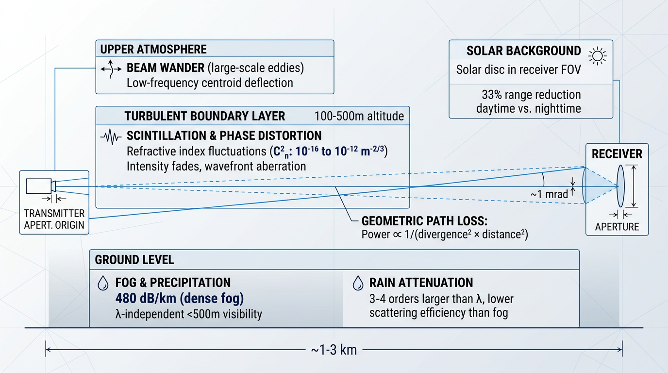
Each of these impairments is well-characterised by established physical models and quantifiable in terms of link margin, probability of fade, and availability impact — which means each one has a corresponding engineering response. The toolkit for addressing them, from link margin allocation and aperture design to hybrid system architectures, is the subject of the next section.
Mitigating atmospheric impairments and hybrid FSO/RF design
Every atmospheric impairment catalogued in the previous section has a corresponding engineering response. Fog, turbulence, scintillation, and rain are not unique to FSO — every wireless and optical technology operates in the same atmosphere, and each has developed a standard toolkit for managing it. For FSO engineers, that toolkit spans link margin design, passive optical techniques, active signal processing, and system-level diversity strategies, culminating in hybrid FSO/RF architecture for applications where single-medium availability is insufficient.
Link margin engineering: the first line of defence
Before any active mitigation is applied, the most fundamental design decision is building a sufficient link margin — the power budget surplus above the receiver sensitivity threshold that absorbs expected atmospheric losses.
As codified in ITU-R P.1814, the link margin is the difference between transmitted power and receiver sensitivity, minus all loss terms: geometrical attenuation, atmospheric attenuation due to fog and rain, scintillation, and system losses including misalignment.
The designer has four primary levers: transmit power, receive aperture size, receiver sensitivity, and beam divergence. Increasing transmit power or aperture area directly improves margin; tightening beam divergence reduces geometric loss at range but demands more precise alignment.
The choice of availability target is what drives the required margin. Enterprise-class availability — typically 99.9%, equating to roughly 8.8 hours of downtime per year — demands a substantially lower margin than carrier-class availability at 99.999%, which permits only around five minutes of downtime annually.
The gap between these two targets is not trivial: fog attenuation at optical wavelengths can exceed 20 dB/km in dense conditions, and no amount of transmit power can fully compensate for thick fog on a long terrestrial link. Link margin engineering sets the baseline from which all other mitigation layers operate.
Hardware and signal-processing mitigation techniques
With link margin established, engineers apply a layered set of techniques targeting specific impairment mechanisms. The following are the principal tools in the FSO mitigation toolkit.
- Aperture averaging: A larger receive aperture spatially averages scintillation-induced intensity fluctuations across its face, reducing received power variance. Passive and cost-effective — no active control required.
- Automatic gain control (AGC): Dynamically adjusts receiver gain to compensate for variations in received optical power, keeping the detected signal within the dynamic range of the receiver electronics during atmospheric fades.
- Forward error correction (FEC): Reed-Solomon, LDPC, and similar codes combined with interleaving correct burst errors caused by atmospheric fades. Interleaving spreads burst errors across codewords so FEC can recover them.
- Adaptive modulation: Dynamically adjusts modulation order and data rate to match current link SNR — dropping to a robust lower-order format under impairment and stepping up to higher-order modulation when conditions allow.
- Adaptive optics (AO): Wavefront sensing and correction via deformable mirrors compensates turbulence-induced phase distortions, critical for coherent receivers and single-mode fibre coupling on satellite-to-ground downlinks.
- Spatial and site diversity: Multiple spatially separated apertures or geographically distributed ground stations reduce the probability of simultaneous deep fades or cloud blockage across all paths.
Aperture averaging and AGC are complementary: aperture averaging reduces the amplitude of intensity fluctuations at the physical level, while AGC accommodates the residual variations in the receiver electronics. Empirical measurements over an 863-metre atmospheric path have confirmed the expected reduction in scintillation index with increasing aperture diameter across weak through strong turbulence regimes, directly informing optimum receiver aperture selection in link design.
On the signal-processing side, FEC with interleaving addresses a specific problem: atmospheric fades produce burst errors rather than random bit errors, and standard FEC codes are designed for the latter. Interleaving converts burst errors into pseudo-random errors that the FEC can correct. Research on interleaver performance in lasercom fading channels characterises this through the temporal diversity parameter L — the number of statistically independent fade events experienced by an individual codeword. SPIE 11993 research shows that significant power penalties exceeding 3 dB develop as L drops below 100, with penalties growing more rapidly when L falls below 10.
Adaptive modulation addresses a different dimension: rate adaptation rather than error correction. Rather than fixing the modulation order and accepting degraded BER during impairment, an adaptive system maintains the target BER by reducing modulation order when SNR falls, then recovering throughput when conditions improve. Research on adaptive subcarrier PSK intensity modulation for FSO has demonstrated significant spectral efficiency gains under moderate-to-strong turbulence conditions without increasing average transmitted optical power, by adapting the modulation order of S-PSK to the instantaneous fading state.
Adaptive optics is the most powerful — and most complex — hardware-level mitigation. A wavefront sensor measures the turbulence-distorted wavefront of the incoming beam, and a deformable mirror corrects the distortion in real time. AO is particularly important in two scenarios: coherent receivers, which require phase-coherent wavefronts to function, and satellite-to-ground downlinks where the received beam must be coupled into single-mode fibre. Atmospheric turbulence destroys the spatial coherence that single-mode coupling demands, and AO is the primary means of restoring it.
The NASA OPALS experiment on the International Space Station demonstrated this directly: using a self-referencing interferometer-based AO system at the Optical Communication Telescope Laboratory, stable fibre-coupled power was achieved across an entire ISS pass, enabling coupling of the downlink into a single-mode fibre receiver and opening the path to higher-bandwidth modulation schemes. The cost and complexity of AO systems make them most justified for high-value links such as satellite-to-ground optical feeder links, rather than short commercial terrestrial deployments where simpler techniques suffice.
Spatial diversity and site diversity
Spatial diversity exploits a physical property of atmospheric turbulence: it is spatially correlated over short distances but becomes de-correlated over separations of tens of centimetres to metres. Multiple spatially separated transmit apertures sending the same data over independent atmospheric paths therefore experience partially independent fading, substantially reducing the probability that all apertures simultaneously suffer a deep fade. Transmitter diversity experiments on the ESA ARTEMIS geostationary satellite confirmed the scintillation reduction achievable with multiple transmit subapertures on the uplink.
Site diversity operates at a larger geographic scale: a network of optical ground stations (OGS) distributed across different locations ensures that cloud cover or local weather at one site does not cause a link outage, because another site in the network can maintain the link. This is the primary tool for achieving high availability on satellite optical ground links, where cloud cover is the dominant outage mechanism — no amount of transmit power penetrates a thick cloud layer.
The scale of OGS networks required to meet typical availability targets is substantial. Poulenard et al. (SPIE 8971) analysed OGS localisation in Europe and found that the minimum number of stations required to reach 99.9% link availability is ten to eleven within Europe, reducing to three or four when the search area is extended to include Africa — reflecting the significantly lower cloud cover probability at lower latitudes.
Hybrid FSO/RF: the complementary failure mode argument
All of the techniques above improve FSO link availability, but none eliminates the fundamental vulnerability to dense fog on terrestrial links. With transmit power constrained by eye-safety regulations, it is physically impossible to overcome the attenuation of thick fog in a single link of meaningful length. This is the engineering reality that motivates hybrid FSO/RF architecture — and the motivation is rooted in physics, not convention.
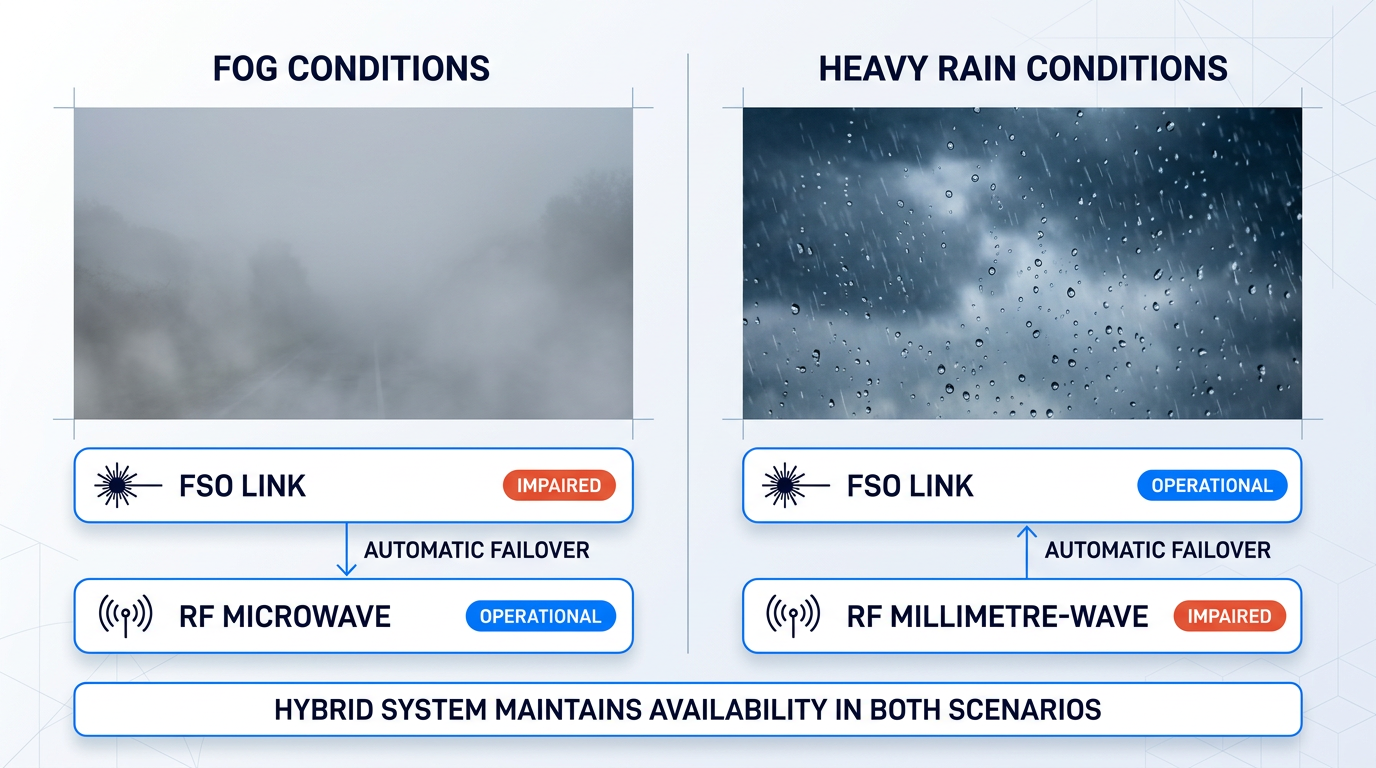
The key physical insight is that fog and rain affect optical and RF wavelengths in opposite ways. Fog consists of water droplets whose diameter is comparable to optical wavelengths, producing strong Mie scattering that can attenuate FSO links by over 20 dB/km in dense conditions. The same fog droplets are far too small relative to microwave RF wavelengths to cause significant attenuation — a microwave link at a few GHz passes through dense fog with negligible loss.
Fog severely attenuates FSO optical wavelengths through Mie scattering but barely affects microwave RF. Heavy rain significantly attenuates millimetre-wave RF (particularly above 10 GHz) through Rayleigh scattering, but has far less impact on FSO optical wavelengths. The two media fail under different atmospheric conditions — their failure modes are complementary, not correlated.
Rain presents the inverse picture. Raindrops are large relative to optical wavelengths, so optical attenuation due to rain is essentially wavelength-independent across commercial FSO bands and relatively modest compared to fog. At millimetre-wave RF frequencies above roughly 10 GHz, however, rain attenuation becomes significant — ITU-R P.838 specific attenuation coefficients show that rain attenuation at 40 GHz rises sharply with rain rate, while FSO optical attenuation at the same rain rate remains comparatively low.
The practical consequence is that a hybrid system pairing FSO with a microwave RF backup path will rarely find both links simultaneously impaired. Fog knocks out the FSO link but leaves the microwave path intact; heavy rain degrades the millimetre-wave RF path but leaves the FSO link largely unaffected. A system exploiting this asymmetry can achieve link availability that neither medium can reach independently — a point confirmed by early hybrid FSO/RF deployments, where automatic fail-over to RF backup links was found to provide availability up to carrier-class 99.999%.
Hybrid FSO/RF architecture and QoS considerations
In a hybrid FSO/RF system, the FSO link operates as the primary high-capacity path — typically delivering Gbps-class throughput — while the RF link serves as the backup path, operating at lower data rates ranging from tens of Mbps to low Gbps depending on the RF technology deployed.
Automatic switchover is triggered by continuous link quality monitoring. When received optical power or bit error rate on the FSO path degrades below a defined threshold, traffic is switched to the RF backup. The ECOC 2024 experimental demonstration of an SDN-controlled hybrid FSO/mmWave system achieved 25-microsecond beam-switching in that specific testbed configuration — illustrating the speed at which software-defined control planes can execute handover between the two media.
The architecture introduces a genuine operational constraint that must be acknowledged honestly: rate disparity. When the FSO link is carrying multi-Gbps traffic and the RF backup can sustain only tens or hundreds of Mbps, the system must either prioritise traffic by QoS class or accept reduced aggregate throughput during RF-only operation. Traffic management mechanisms — priority queuing, traffic shaping, and graceful rate reduction — are essential design elements. High-priority traffic continues to flow; lower-priority bulk data accepts queuing or temporary rate reduction.
Choosing the right architecture: hybrid vs. standalone FSO
The decision between hybrid FSO/RF and standalone FSO is a systems engineering judgement, not a product preference. The right architecture depends on the availability requirement, the atmospheric environment, and the feasibility of deploying an RF backup path.
Hybrid FSO/RF is the appropriate choice when carrier-class availability is required in fog-prone geographies — dense urban terrestrial links, coastal environments — where the FSO link alone cannot meet the availability target, and where an RF backup path is physically and economically feasible.
Standalone FSO is appropriate when the link operates in vacuum (inter-satellite links experience no atmospheric attenuation and require none of the mitigation techniques described here), when the link is short with generous margin and enterprise-class availability suffices, or when the deployment environment has genuinely low fog probability.
The availability arithmetic for fog-prone terrestrial environments typically points firmly toward hybrid architecture wherever carrier-class uptime is contractually required. The engineer's task is to match the architecture to the availability target and the atmospheric statistics of the specific deployment location — not to default to either approach without that analysis.
With the engineering toolkit for atmospheric resilience established, there is another dimension of FSO's technical character that deserves attention — one that is particularly significant for defence and government applications: the inherent security properties that arise from FSO's physical layer.
EDFA Technology Built for FSO Signal Challenges
Atmospheric impairments demand robust signal amplification. Our custom EDFAs are tailored for free-space optical communications, delivering on-demand modulation at high average output powers.

Security Characteristics of FSO Links
FSO's security advantages are not engineered add-ons bolted onto the link design — they are a direct consequence of the physics of optical propagation. A beam that diverges at milliradians, produces no electromagnetic signature outside its path, and operates in unlicensed optical spectrum carries security properties that RF systems cannot replicate, regardless of how those RF systems are configured.
Physical-Layer Security Properties
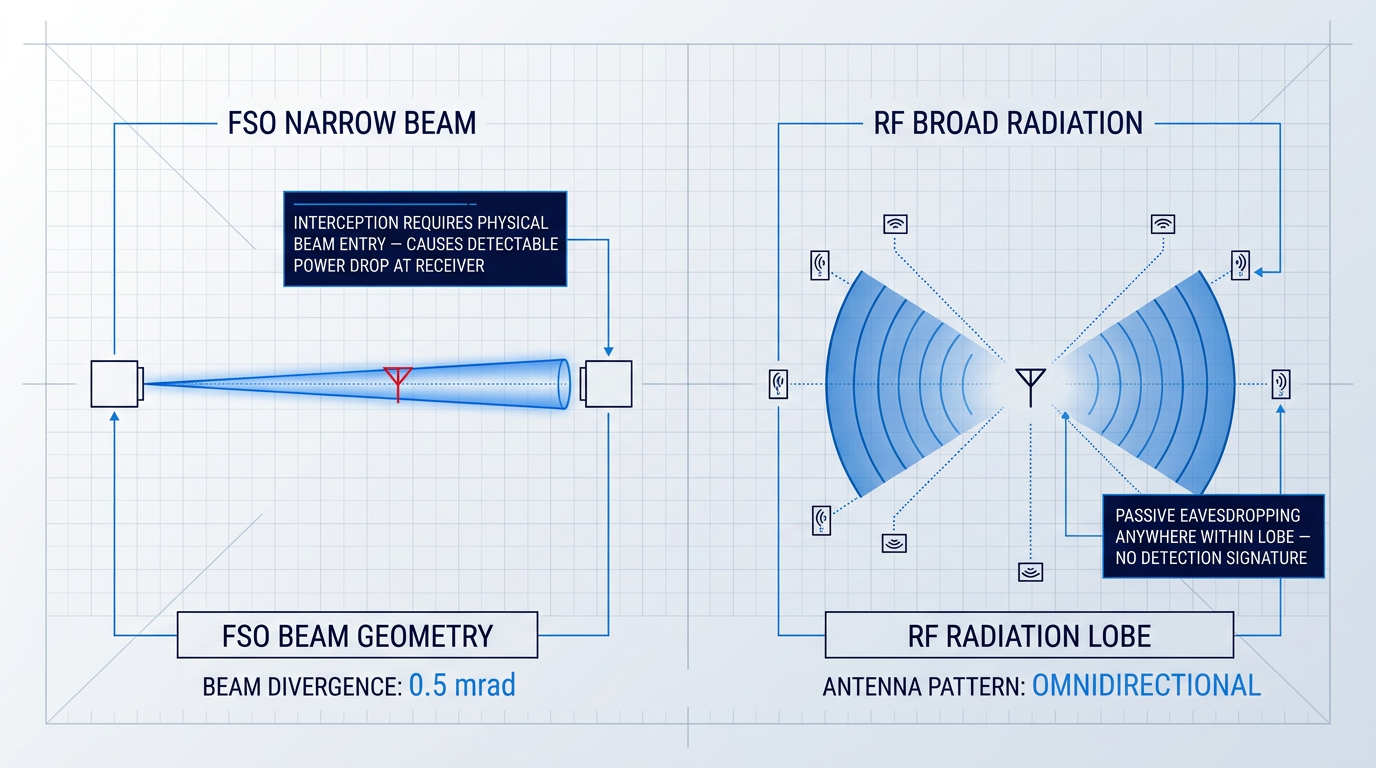
The most fundamental security property of an FSO link is its narrow beam geometry. Beam divergence in FSO systems is governed by the ratio of carrier wavelength to transmitter aperture diameter, producing beams that diverge at milliradians — a fundamentally different geometry from the broad radiation lobes of RF antennas, which illuminate large volumes of space and can be received by any antenna within range.
In practical terms, this geometry means that intercepting an FSO beam requires an adversary to physically enter the beam path between transmitter and receiver. Doing so necessarily diverts a portion of the optical power, causing a measurable power drop at the intended receiver — a signature that passive RF eavesdropping never produces.
This detectability of interception is a meaningful operational property. Unlike passive RF monitoring, where an adversary can receive the carrier signal without the legitimate receiver ever knowing, FSO interception is an active, physically intrusive act that announces itself through the link budget.
The second key property is the complete absence of an RF electromagnetic signature. FSO transmissions are invisible to spectrum monitoring equipment, direction-finding receivers, and spectrum surveillance systems — because there is no RF carrier to detect. This directly satisfies low-probability-of-intercept / low-probability-of-detection (LPI/LPD) requirements that are increasingly specified in defence and government procurement.
In RF communications, the carrier is detectable by any receiver within the antenna's radiation pattern, regardless of whether that receiver is authorised. In FSO, the signal exists only within the beam path. As one industry expert summarised in Military Aerospace coverage of the technology, government customers are explicitly "exploiting the low probability of interference and low-probability-of-detection attributes and employing laser communications in covert scenarios or in an RF denied environment."
FSO's resistance to jamming rests on two complementary mechanisms. First, FSO operates in unlicensed optical spectrum — there is no frequency allocation to target and no carrier frequency to overpower with a competing RF signal. Second, the narrow acceptance angle of FSO receivers means that injecting an optical jamming signal requires physical placement within the beam path, which is operationally difficult and, as noted above, detectable.
These two mechanisms are distinct but reinforce each other: the spectral mechanism removes the RF jamming vector entirely, while the geometric mechanism makes optical jamming a physically demanding and self-exposing act. The honest position is that FSO jamming is extremely difficult, not impossible — a sufficiently resourced adversary with physical access to the beam path retains options.
Honest Limitations of FSO Physical-Layer Security
These properties are real and physics-grounded, but they operate at the link layer only. A technically literate reader should be clear on what they do and do not guarantee.
- Encryption remains essential: A link that is difficult to intercept is not an encrypted link. End-to-end cryptographic security is still required for classified or sensitive communications.
- Beam waist eavesdropping: Eavesdropping is theoretically possible away from the beam waist, where divergence broadens the beam footprint — a more significant risk on longer terrestrial links.
- Physical beam path access: If an adversary can access the physical path between terminals — at ground level in an urban environment, for instance — geometric security properties are weakened.
- Pointing accuracy is a prerequisite: A misaligned link with beam spillage beyond the intended receiver aperture degrades the geometric security properties the system relies on.
The beam waist limitation is worth dwelling on. IEEE research into physical-layer security of FSO communications confirms that eavesdropping attacks can be performed by detecting a small portion of the light beam, and that this risk is most pronounced "at the free space range away from the beam waist where the beam size is large" — a scenario particularly relevant for longer terrestrial links where cumulative divergence increases the beam footprint significantly.
The pointing accuracy point has a direct operational implication: the same beam discipline that maintains link availability also maintains the geometric security properties. A system that is drifting or poorly maintained does not simply degrade in throughput — it also degrades in its physical-layer security posture.
FSO's narrow beam geometry makes interception physically intrusive and detectable — but a link that is hard to intercept is not the same as an encrypted link. For classified or sensitive traffic, end-to-end cryptographic security architecture is required alongside FSO's physical-layer properties, not instead of them.
Relevance in Contested and Congested Environments
For defence and government operators, FSO's security profile is most valuable in environments where RF is contested, jammed, or denied. In anti-access/area-denial (A2AD) environments, where adversaries actively target RF communications, FSO's immunity to RF jamming and its absence of an RF signature make it a compelling alternative — not as a wholesale replacement for RF, but as a communications layer that operates in a domain adversaries cannot easily attack.
Covert communications represent a specific use case where the LPI/LPD property is operationally decisive. A link that produces no detectable RF signature cannot be located by direction-finding equipment, cannot be identified by spectrum surveillance, and cannot be jammed by an adversary who does not know it exists.
Military and government procurement specifications increasingly include LPI/LPD requirements as an explicit driver for FSO adoption, particularly for tactical and battlefield communications where spectrum control cannot be assumed. SPIE and Military Aerospace coverage of FSO deployment confirms that these applications — covert links, RF-denied environments, and A2AD scenarios — represent a primary growth vector for the technology in the defence sector.
Realising these security properties in practice, however, depends on operational discipline: accurate and stable pointing, physical integrity of the beam path, and rigorous link monitoring. Those operational considerations — and what they demand of the teams deploying FSO systems — are the subject of the next section.
FSO in Operation: Deployment, Maintenance, and Trajectory
Designing an FSO system and operating one over years are two very different disciplines. The engineering choices made at procurement time — hardware architecture, configurability, support model — determine whether a deployed link performs as specified across its full service life, or becomes a maintenance burden the moment conditions deviate from the design envelope.
Alignment, hardening, and link monitoring
Establishing a link requires precision at two levels: coarse acquisition, using GPS, INS data, or pre-surveyed mount positions to bring the beam within the capture range of the receiver, and fine pointing, where optical tracking loops and fast-steering mirrors close the loop to sub-microradian accuracy.
Once a link is established, it must be actively maintained. Slow pointing drift — driven by thermal expansion of mounting structures, building sway, and low-frequency vibration — accumulates continuously and must be managed by the tracking system rather than corrected manually at intervals.
Outdoor terminals must also be engineered for the physical environment: temperature extremes, humidity, wind loading, and precipitation all place demands on the enclosure and optical assembly. Optical surfaces accumulate contamination over time, and periodic cleaning is a maintenance discipline, not an edge case. Laser sources carry finite lifetimes, and replacement planning should be built into the operational lifecycle from the outset.
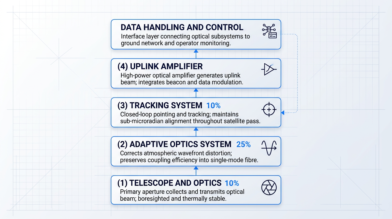
At the link level, real-time monitoring of received optical power and bit error rate (BER) is standard practice, with automated alerts allowing operators to respond to degradation before an outage occurs. For satellite optical ground stations, however, the monitoring challenge is compounded by the integration complexity of the station itself.
- Telescope and optics: The primary aperture that collects and transmits the optical beam; must be precisely boresighted and thermally stable.
- Adaptive optics system: Corrects wavefront distortion introduced by atmospheric turbulence, preserving coupling efficiency into single-mode fibre.
- Tracking system: Closed-loop pointing and tracking assembly maintaining sub-microradian alignment throughout a satellite pass.
- Uplink amplifier: High-power optical amplifier generating the uplink beam; must integrate cleanly with beacon, modulation, and data subsystems.
- Data handling and control: The interface layer connecting the optical subsystems to ground network infrastructure and operator monitoring tools.
These subsystems must operate as a coherent whole. When one is procured from a catalogue and another from a specialist manufacturer, integration responsibility falls to the operator — and so does the support burden when something fails in service. The operational case for purpose-built, manufacturer-supported hardware is a procurement argument, not a marketing one: systems in demanding environments benefit from direct engineering access, the ability to modify hardware to evolving requirements, and a support chain that does not terminate at a reseller.
Woodrow Scientific's EDFA for satellite ground links is a concrete example of purpose-built OGS hardware designed around exactly this integration picture. Its single-beam beacon and data architecture nests the tracking beacon and uplink data in one amplified beam — the beacon carried at low modulation depth and the data modulated above it — removing the need for a separate beacon transmitter in the station stack.
The amplifier is configured end-to-end across both hardware and software to the client's ground station: band (C-band, L-band, or dual-band from a single source), output power, emitter configuration, and cooling are set at build; the software layer applies Modulation-on-Demand, with software-selectable waveform, frequency, and modulation index, and the combined beacon and data modulation switchable across CCSDS, SDA, and proprietary standards at high power.
Woodrow Scientific designs, builds, qualifies, and supports its amplifiers entirely in-house, on patented technology, with engineering expertise rooted in Southampton's Optoelectronics Research Centre — the birthplace of the EDFA.
That in-house model matters operationally: many suppliers in this market are resellers or importers, which limits their ability to provide deep engineering support, accelerate spares, or modify the product when a programme's requirements change. The amplifier carries CE and UKCA certification and is supplied to ground station integrators worldwide.
The trajectory of FSO: scale, standards, and new platforms
The architectural direction for satellite optical ground infrastructure is clear: away from single, isolated stations and towards geographically distributed OGS networks where site diversity is a designed-in operational property rather than a fallback measure.
At the programme level, FSO standardisation work is active across multiple bodies — and the standards are still maturing. Protocol and waveform specifications are advancing in parallel, which creates a practical procurement risk: fixed-function ground equipment procured against today's specification may require hardware replacement as standards evolve, while configurable equipment can be updated through software.
In a field where optical link standards are still developing across multiple bodies and programmes, ground equipment that can be reconfigured across waveforms and protocols without hardware replacement protects the programme investment in a way that fixed-function hardware cannot.
At the platform level, FSO is expanding to smaller and more constrained hosts. Research into optical phased arrays — solid-state beam steering with no moving parts — and MEMS-based beam directors is aimed at reducing the size, weight, and power (SWaP) of pointing, acquisition, and tracking systems to levels compatible with small satellites and UAV platforms that cannot accommodate current mechanical gimbal assemblies. These are near-term development threads, not deployed capabilities, but the trajectory is consistent.
In terrestrial networks, FSO is increasingly discussed as a complementary technology for dense urban deployments where RF spectrum capacity is under sustained pressure — point-to-point optical backhaul filling the capacity gaps that radio cannot address without additional licensed spectrum. The structural drivers — growing satellite constellation throughput demands and the RF bandwidth ceiling — are not cyclical pressures; they are the conditions the field is designing into.
With the operational picture and the forward trajectory now in view, the final section draws together the key threads from across this guide — characterising where FSO sits as a mature technology, where its boundaries remain, and what that means for those evaluating or deploying it.
Conclusion
FSO: a mature technology with an expanding role
Free space optical communications is not a technology waiting for its moment — it has decades of operational engineering behind it, from early terrestrial links to the laser crosslinks now threading commercial satellite constellations together.
The atmospheric constraints are real and shape every deployment decision; the point is that the toolkit for addressing them is mature and well-understood.
With the RF spectrum ceiling pressing harder and the satellite domain expanding rapidly, FSO is moving toward the centre of next-generation infrastructure — not the periphery.
Frequently asked questions about free space optical communications
Answers to the most common questions about how FSO works, how far it reaches, and how it compares to other wireless technologies.
A classic example is a building-to-building FSO link, where a laser transceiver mounted on one rooftop transmits data across a street or campus to a paired unit on an adjacent building — no fibre trench, no radio licence required. Beyond terrestrial links, NASA's Lunar Laser Communication Demonstration (LLCD) in 2013 achieved a 622 Mbps downlink from lunar distance (approximately 400,000 km), establishing that high-rate optical links are viable across deep-space distances. At commercial scale, SpaceX Starlink deploys inter-satellite laser crosslinks between its constellation satellites, carrying traffic across thousands of kilometres in the vacuum of space — the largest operational FSO network currently in existence.
Free space optical communication works by encoding data onto a laser beam and transmitting it through open air or vacuum, without any physical waveguide connecting the two ends. At the transmitter, a laser source is modulated to carry the data signal. The beam then propagates through free space — atmosphere, vacuum, or both — until it reaches the receiver, where a collecting aperture (typically a telescope or lens) gathers the light, a photodetector converts it back to an electrical signal, and a demodulator recovers the original data. A clear line-of-sight path between transmitter and receiver is required; any obstruction or severe atmospheric event in the beam path will interrupt the link.
Range in FSO depends heavily on the deployment domain, and atmospheric conditions — not raw physics — are the binding constraint for terrestrial links. Terrestrial commercial FSO systems typically operate over distances from around 50 m up to a few kilometres. At longer terrestrial ranges, fog is the dominant limiting factor: dense fog can attenuate a beam so severely that link availability, rather than distance alone, determines what is practical. Satellite inter-satellite links (ISLs) operate over thousands of kilometres in the vacuum of space, where atmospheric impairments are absent — Starlink's laser crosslinks are a working example. Ground-to-satellite links span distances from roughly 500–2,000 km for low Earth orbit up to approximately 36,000 km for geostationary orbit, with the atmospheric portion of the path (the lowest tens of kilometres) being the turbulence-critical segment. At the extreme end, NASA's LLCD demonstrated high-rate optical communication at lunar distance (~400,000 km).
The two dominant wavelength bands in commercial FSO systems are 850 nm and 1550 nm. The 1550 nm band is preferred for high-performance links for three reasons: it falls within an eye-safety window where the cornea and lens absorb the beam before it reaches the retina, allowing higher permissible transmit power; it sits within a low-loss atmospheric transmission window; and it aligns with the C-band and L-band wavelengths around which the entire fibre-optic amplification ecosystem — including erbium-doped fibre amplifiers (EDFAs) and associated components — was built, giving 1550 nm systems access to decades of mature, cost-effective hardware. The 850 nm band remains in use for shorter-range, lower-power links where component simplicity and cost matter more than maximum performance.
FSO and Li-Fi are both optical wireless technologies, but they serve entirely different purposes. FSO is a point-to-point link technology: it uses a collimated laser beam to connect two fixed or semi-fixed points — rooftops, satellites, ground stations — over distances ranging from tens of metres to thousands of kilometres. Li-Fi is an access technology: it uses diffuse LED illumination from ceiling-mounted fixtures to provide wireless coverage to multiple devices within a room, much like Wi-Fi. The two are complementary rather than competing — a Li-Fi access point serving devices inside a building might itself connect to the wider network via an FSO backhaul link on the rooftop.
Generally yes, for short distances, though with a power penalty. Standard clear glass transmits well at both 850 nm and 1550 nm, but each glass surface introduces some absorption and Fresnel reflection loss. The more significant concern is coated or tinted glass — UV-blocking films, solar control coatings, and low-emissivity glazing can introduce substantial additional attenuation and may degrade link performance considerably, depending on the specific coating chemistry. For occasional or temporary deployments, operating through a standard uncoated window is typically feasible. For permanent, high-availability links, a small through-wall aperture is preferable to eliminate the uncertainty introduced by glass type and coating.