

Introduction
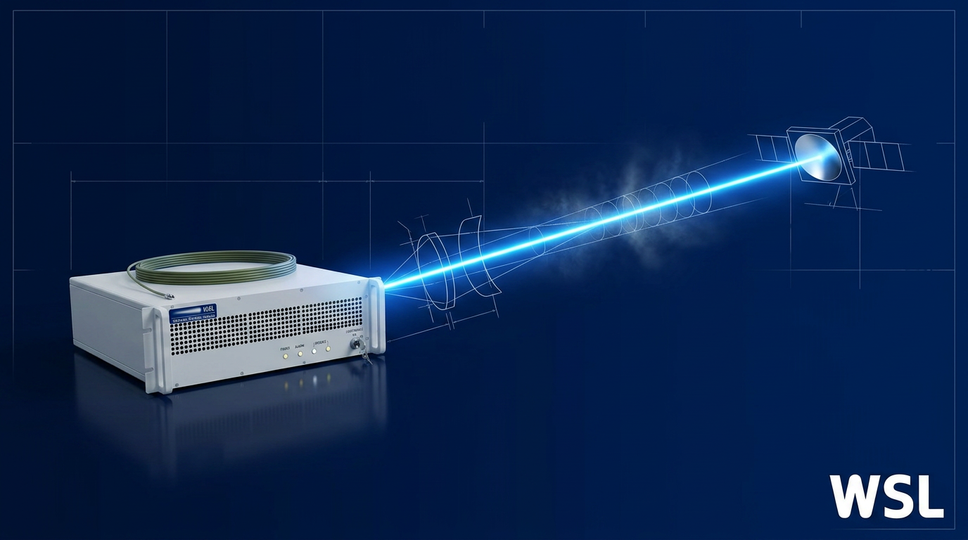
If you're here, you already know what free space laser communication is — what you want is to understand how it actually works, step by step, from the moment a signal enters the transmitter to the moment it's recovered at the receiver.
This walkthrough follows the FSO signal chain in physical sequence: laser generation and beam conditioning, modulation, amplification, propagation, atmospheric mitigation, pointing and tracking, and finally detection and decoding.
At each stage, the focus is on the engineering decisions embedded in the design — the trade-offs that separate a system that closes its link from one that doesn't.
TL;DR
A free-space optical link is not a single technology — it is a chain of interdependent engineering decisions, each constraining the next.
Understanding the full sequence in order is what gives you the mental model to specify, evaluate, and troubleshoot a real FSO system — not just describe one.
This article covers:

Laser source generation and beam conditioning
Encoding data via beam modulation
High-power amplification for the link
Beam propagation and link budget
Mitigating atmospheric degradation
Beam pointing, acquisition, and tracking
What is free space laser communication?
Free-space optical (FSO) communication is a wireless technology that transmits data on modulated laser beams propagating through free space — air, vacuum, or outer space — without physical cables. Both FSO and fibre optics use light to carry data; the fundamental difference is the transmission medium: fibre confines and guides the beam through a glass waveguide, while FSO transmits it across an unguided open path.
FSO is inherently a line-of-sight technology: both terminals require an unobstructed optical path between them, and this constraint shapes every engineering decision that follows — from beam pointing to site selection.
The dominant operating wavelength in FSO systems is 1550 nm, and the choice is not arbitrary. Three distinct engineering factors converge to make it the practical default over shorter alternatives such as 850 nm.
The first factor is eye safety. Wavelengths beyond 1400 nm are absorbed in the anterior structures of the eye — the cornea and lens — and cannot reach the retina. This raises the maximum permissible exposure (MPE) significantly compared to 850 nm or 1064 nm, where light is still focused onto the retina. Higher permitted power means longer links and better margin under adverse propagation conditions.
The second factor is the atmospheric transmission window. At 1550 nm, molecular absorption losses are low — a property that makes it one of the preferred wavelengths for both FSO communications and long-range sensing applications.
The third factor is the telecom-grade component ecosystem. Because 1550 nm is the operating wavelength of the global fibre-optic telecommunications infrastructure, FSO designers can draw directly on a mature, cost-competitive supply chain: laser diodes, high-speed modulators, erbium-doped fibre amplifiers (EDFAs), and sensitive photodetectors — all developed and manufactured at scale for the telecoms market.
By contrast, 850 nm laser diodes are cheaper and simpler to source, but they operate under tighter eye-safety power limits and sit outside the telecom component ecosystem. In practice, this constrains 850 nm systems to shorter links and lower transmitted power, with less headroom when propagation conditions deteriorate.
The 1550 nm wavelength unlocks higher transmit power (eye-safe above 1400 nm), low atmospheric molecular absorption, and direct access to the entire fibre-telecom component supply chain — three independent advantages that no shorter wavelength can match simultaneously.
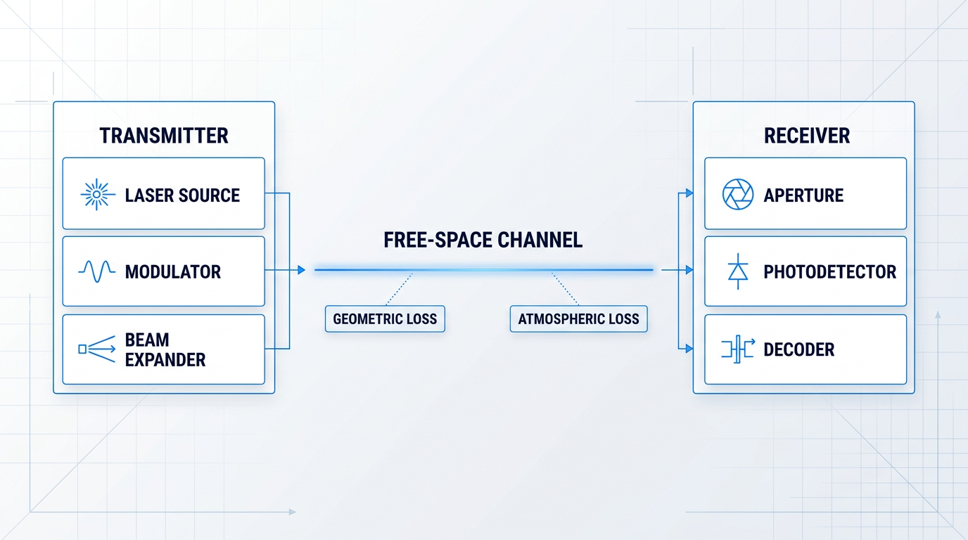
With the wavelength rationale established, the link itself can be understood as three functional stages: a transmitter that generates and conditions the optical signal, a free-space channel through which the beam propagates, and a receiver that captures and decodes it.
- Transmitter: Laser source, modulator, and beam-conditioning optics. Covered in Steps 1–3 of the signal-chain walkthrough.
- Free-Space Channel: The open propagation path through the atmosphere, including geometric and atmospheric loss effects. Covered in Steps 4–5.
- Receiver: Aperture, photodetector, and signal decoder, with pointing and tracking (Step 6) keeping the link aligned. Covered in Steps 6–7.
This three-part architecture is the scaffold for the walkthrough ahead — each stage maps directly to the steps that follow, and understanding the boundaries between them is what makes the signal-chain logic clear.
The schematic below shows the complete link from end to end, with key components labelled at each stage.
FSO links are capable of carrying data at rates from hundreds of Mbps to multiple Gbps — and beyond, in research configurations — operating licence-free in most jurisdictions, since optical wavelengths fall outside regulated radio-frequency spectrum.
The signal chain begins at the transmitter, where the optical carrier is generated and conditioned before it ever enters the open path — and that is where the walkthrough starts.
Step 1
Generate and condition the optical carrier

Key Insights
Coherence is a prerequisite, not a bonus.
M² is a direct link-budget parameter.
Wider output aperture means tighter beam at range.
The optical carrier in a free-space optical system is a coherent, narrow-linewidth laser beam at a stable, precisely defined wavelength — not a broadband or incoherent light source.
Coherence and wavelength stability are not incidental properties: they are the prerequisites that make modulation and detection possible at all.
Choosing a laser source architecture
Two source architectures dominate commercial and high-performance FSO systems, and your choice between them shapes every subsequent stage of the link.
- Laser diodes: Compact and efficient, laser diodes are the workhorse of commercial FSO terminals. External-cavity configurations improve spectral purity significantly over direct-emitting variants, making them suitable for higher-performance links.
- MOPA (master oscillator power amplifier): A spectrally pure, low-power seed laser sets the wavelength and coherence properties; a separate amplifier stage boosts output power without degrading them. This separation of spectral control from power generation is the key engineering advantage of MOPA, and it is the dominant architecture for high-power FSO uplinks.
With MOPA, the seed laser does the precision work and the amplifier does the heavy lifting — the two functions do not compete.
Beam quality and the M² factor
Once you have a source, understand what M² means for your link budget: it is not an abstract quality score, it is a direct predictor of how much power reaches the receive aperture.
A beam with M² close to 1.0 is near-diffraction-limited — it diverges at the minimum physically possible rate for its wavelength and aperture size.
A beam with M² significantly above 1.0 diverges faster, spreads its energy over a larger area at range, and delivers less power to the receiver — a deficit that no downstream component can recover.
Collimation and beam expansion
The raw output of a laser diode is highly divergent and cannot be transmitted directly — collimation optics reshape it into a parallel beam before anything else happens.
After collimation, a beam expander increases the output aperture diameter, which reduces far-field divergence: because divergence is inversely proportional to aperture size, a wider beam at the transmitter produces a tighter, more concentrated beam at range.
Beam conditioning is the bridge between raw laser output and the well-formed transmit beam that every downstream step depends on.
Wavelength selection is also a source-specification decision: operating within a low-absorption atmospheric transmission window — such as the 1550 nm band already discussed — avoids compounding atmospheric loss on top of geometric path loss.
With a coherent carrier at the right wavelength, conditioned to near-diffraction-limited quality and expanded to the correct output aperture, the beam is ready to carry a modulated data signal.
Step 2
Modulate the beam to encode data

Key Insights
OOK requires no local oscillator.
Sensitivity scales with complexity.
With the conditioned optical carrier established in Step 1, the next stage is modulation: impressing an electrical data stream onto the beam by varying one of its physical properties — intensity, phase, timing, or polarisation.
The modulation scheme chosen here propagates through every downstream design decision, from receiver architecture to atmospheric resilience to link margin.
The four principal FSO modulation schemes
Intensity modulation with direct detection (IM/DD) using on-off keying (OOK) is the dominant approach in commercial free-space optical systems.
In OOK, the laser switches on for a binary 1 and off for a binary 0 — the detector responds to optical power, requiring no local oscillator or interferometric receiver.
The trade-off is sensitivity: because the detector must distinguish signal from noise on intensity alone, OOK bit error rate degrades directly when atmospheric turbulence causes intensity fading (scintillation).
Differential phase shift keying (DPSK) encodes data in phase transitions between successive symbols rather than in absolute intensity.
At the receiver, a delay-line interferometer compares each symbol's phase against its predecessor, converting phase transitions into intensity differences that a direct-detection photodiode can read.
DPSK offers approximately a 3 dB sensitivity improvement over OOK at the same data rate, meaning the link can close at roughly half the received optical power for the same bit error rate.
The cost is a more complex receiver front-end; phase-sensitive formats also interact with turbulence-induced phase distortions differently from intensity-based schemes, which matters when characterising link margin under atmospheric stress.
Pulse position modulation (PPM) encodes data in the timing position of an optical pulse within a fixed time slot: the slot is divided into M sub-slots, the pulse occupies one, and each symbol carries log₂M bits.
Because peak power is high relative to average power, PPM achieves very high photon efficiency — making it the preferred format for power-limited or photon-starved links, including deep-space optical communications.
The trade-off is bandwidth: PPM exchanges spectral efficiency for power efficiency, and the receiver must maintain precise symbol-timing synchronisation.
Polarisation shift keying (PolSK) encodes data in the polarisation state of the beam rather than in its intensity or phase.
Atmospheric turbulence primarily causes intensity fading (scintillation) rather than polarisation rotation, so PolSK carries an inherent resilience advantage against turbulence-induced intensity fluctuations.
PolSK requires a polarisation-sensitive receiver capable of resolving polarisation states — a niche but meaningful option for turbulence-heavy link scenarios.
Comparing schemes across key trade-off axes
No single scheme dominates across all axes — the right choice depends on whether the link is power-constrained, bandwidth-constrained, or turbulence-dominated.
| Scheme | Detection type | Sensitivity vs OOK | Turbulence resilience | Bandwidth efficiency |
|---|---|---|---|---|
| OOK (IM/DD) | Direct | Baseline | Low — scintillation degrades BER directly | High |
| DPSK | Direct (delay-line interferometer) | ~3 dB better | Moderate — phase distortions interact differently | High |
| PPM | Direct | High (photon-efficient) | Moderate — timing sync required | Low — trades bandwidth for power |
| PolSK | Polarisation-sensitive direct | Comparable to OOK | High — inherently insensitive to intensity fading | Moderate |
Comparing the four FSO modulation schemes across the four key design trade-off axes gives engineers a compact decision reference without requiring them to hold all the prose detail in memory simultaneously.
The modulation scheme also determines receiver architecture: OOK and PPM suit simple direct-detection photoreceivers; DPSK requires a delay-line interferometer; PolSK requires polarisation discrimination optics — all elaborated in Step 7.
From an atmospheric resilience perspective, scheme choice is one of the levers available before any active mitigation technique is applied — a point that becomes important when Step 5 addresses adaptive optics and other impairment-compensation strategies.
FSO standards (CCSDS, SDA, and proprietary protocols) are still maturing. A terminal locked to one modulation scheme at the hardware level faces obsolescence risk as standards evolve. Specifying the ability to switch modulation waveforms and adjust parameters — waveform shape, modulation depth, modulation index — without hardware replacement is sound engineering practice for any ground station or terminal that must remain interoperable across a standards transition.
The modulated signal exits the modulator at milliwatt-class power levels and is ready for amplification — the subject of Step 3.
Step 3
Amplify the Transmit Signal
Key Insights
EDFA amplification bridges milliwatt seed to watt-level output.
Output power, M², ASE, and SBS all matter.
Software-definable amplifiers future-proof the ground station.
The modulated seed signal leaving the optical modulator in Step 2 carries your encoded data — but at milliwatt-level power, it cannot survive the geometric spreading loss and atmospheric attenuation of a real free-space optical link.
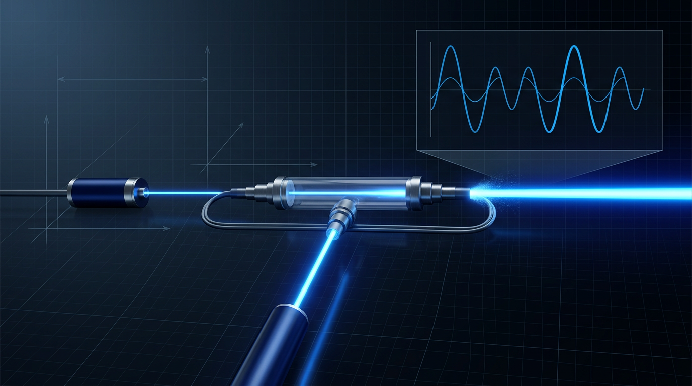
Boost that signal using an erbium-doped fibre amplifier (EDFA) — the standard amplification technology for FSO systems operating at 1550 nm.
Inside the gain fibre, erbium ions are excited by a pump laser (typically at 976 nm or 1480 nm) and release that energy via stimulated emission as the signal photons pass through, amplifying the optical signal without converting it back to an electrical domain.
The C-band (1530–1565 nm) and L-band (1565–1625 nm) are the primary operating windows, covering the wavelengths used in virtually all current FSO uplink designs.
Use a MOPA Architecture to Separate Quality from Power
Structure the transmit chain as a master oscillator power amplifier (MOPA): the seed laser acts as the master oscillator, generating a spectrally pure, precisely modulated signal; the EDFA acts as the power amplifier, scaling that signal to the output power the link demands.
The architectural insight is separation of concerns — spectral purity and modulation fidelity are governed by the seed stage, output power by the amplifier stage, and each can be optimised independently without compromising the other.
For a ground-to-satellite uplink, that output power needs to reach the watt level to close the link budget against the geometric path loss that grows with the square of range.
Four Amplifier Parameters That Determine Link Performance
- Output power: Sets the transmit power term in the link budget. Insufficient power at this stage means the link cannot close, regardless of how well every other component performs.
- Beam quality (M²): The amplifier must preserve near-diffraction-limited output — M² close to 1.0. A degraded M² causes the beam to diverge faster, reducing power density at the receiver aperture at range.
- ASE noise and noise figure: Amplified spontaneous emission (ASE) adds broadband optical noise to the signal. The amplifier's noise figure sets the floor on achievable signal-to-noise ratio at the receiver.
- SBS management: Stimulated Brillouin scattering is a nonlinear effect that limits how much power can be propagated in single-mode fibre at high continuous-wave levels. A well-engineered high-power EDFA manages SBS to reach full output without spectral degradation.
Amplification is a precision engineering discipline: output power, beam quality, and modulation fidelity must all be maintained simultaneously — not traded against each other.
Design for Configurability, Not a Single Fixed Spec
The FSO standards landscape is still maturing — CCSDS, SDA, and proprietary waveforms coexist today, and the standards a ground station must support in three years may differ from those it supports now.
An amplifier that is configurable across wavelength, modulation scheme, modulation index, waveform shape, and beacon behaviour without hardware replacement is the correct engineering posture for a ground station built to outlast the current standards cycle.
A software-definable amplifier lets the ground station adapt as FSO standards evolve — protecting the investment without requiring a hardware swap when CCSDS or SDA requirements change.
This principle extends naturally to the beacon layer: rather than running a separate beacon beam alongside the data path, a better architecture nests the tracking beacon and the uplink data within a single amplified output.
Nesting both in one beam eliminates the alignment uncertainty that arises when beacon and data travel separate optical paths — a practical advantage that becomes significant at the pointing accuracies required for satellite links.
Woodrow Scientific's EDFA: This Architecture in Practice
Woodrow Scientific's EDFA is built around exactly this design philosophy — a high-power, software-definable amplifier for satellite ground links that delivers 10 W average output at 1550 nm with M² < 1.1 beam quality.
Its single-beam beacon-and-data architecture nests the tracking beacon at a low modulation depth and the uplink data above it in one amplified output, so both functions are served by a single beam with no separate optical path to align.
The amplifier is configured end-to-end at the point of manufacture: hardware configuration covers band (C-band, L-band, or dual-band from a single source), output power, emitter count, cooling, and external seed input; the software layer — WSL's Modulation-on-Demand — provides software-selectable waveform (square or sinusoidal), adjustable frequency and modulation index, combined beacon and data modulation, and switchability between CCSDS and SDA standards at full power.
This is end-to-end bespoke configurability across both the physical build and the control layer — not catalogue selection from a fixed menu of options.
WSL designs, builds, qualifies, and supports its amplifiers entirely in-house on patented technology, with engineering heritage rooted in Southampton's Optoelectronics Research Centre — the birthplace of the EDFA.
A significant portion of the amplifier market is served by resellers and importers rather than manufacturers, which in practice means limited in-house engineering support, slower spares, and no ability to modify or improve the product for a specific programme.
The amplifier ships in a 3U 19" rack form factor, is CE and UKCA certified, and is made in Britain.
With the transmit signal now amplified to the required output power and beam quality, it is ready to propagate — and Step 4 addresses whether that power is sufficient to close the link budget across the geometry of the path.
EDFAs Built for Free-Space Optical Links
The EDFA is the amplification backbone of any 1550 nm FSO system. Explore tailored EDFA solutions designed specifically for free-space optical communications, from datasheet to custom configuration.

Step 4
Propagate the beam and account for the link budget
Key Insights
Aperture size on both ends drives geometric loss.
Tighter beam, harder pointing problem.
With the transmit signal amplified to its output power, the beam exits the aperture and enters free space — and from this point forward, physics imposes losses that no amount of amplification can retroactively recover.
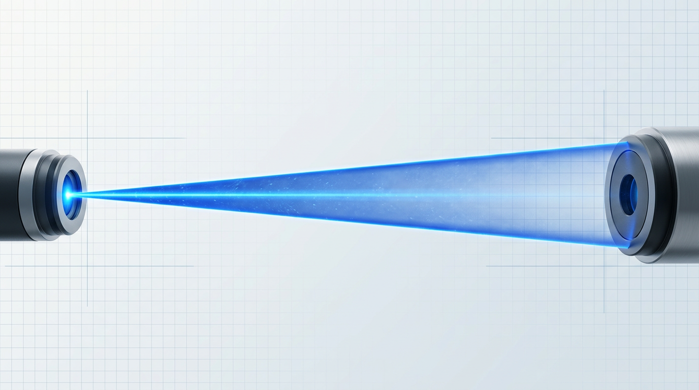
The first loss is diffraction. As a laser beam propagates, it spreads due to the wave nature of light — a fundamental consequence that cannot be eliminated, only minimised by design.
The divergence angle governs how quickly the beam expands. For a diffraction-limited beam, this angle is set by the ratio of wavelength to transmit aperture diameter: a larger aperture produces a narrower beam and therefore lower geometric loss at range.
The practical intuition is straightforward: doubling the range quadruples the beam's cross-sectional area at the receiver, so the fraction of optical power captured by a fixed receive aperture falls by a factor of four.
Geometric path loss is the quantitative expression of this spreading. It is the ratio of the receiver aperture area to the beam's cross-sectional area at range — and because that beam area grows with the square of range, geometric loss scales with range squared.
This differs conceptually from the inverse-square law governing isotropic radiators. FSO loss is driven by beam geometry — specifically the interplay of divergence angle, link range, and aperture sizes — not by radiation spreading uniformly in all directions.
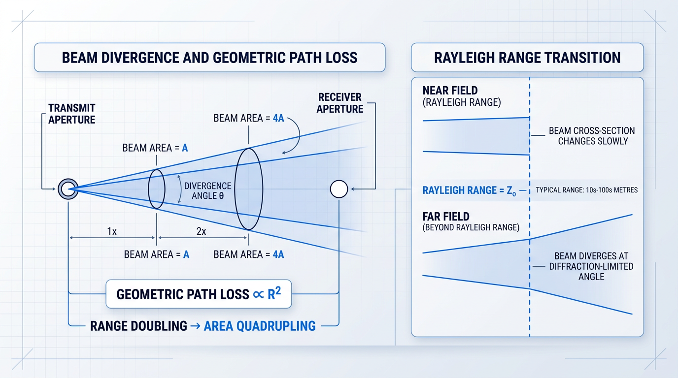
Before the beam enters the far field, there is a near-field region — within the Rayleigh range — where it remains approximately collimated and its cross-section changes slowly with distance.
The Rayleigh range is the distance from the beam waist at which the beam's cross-sectional area has doubled. Beyond it, the beam enters the far field and diverges at the diffraction-limited angle, with radius growing approximately linearly with distance.
For practical free space laser communication links, the Rayleigh range is typically on the order of tens to hundreds of metres depending on aperture size and wavelength. Any link spanning more than a few hundred metres is operating in the far field — this is the normal regime, not an edge case, and the link budget must reflect it.
The link budget is the engineering tool that answers the central question of link design: does this link close? It is a power accounting exercise performed in the dB domain, and it ties together every element of the signal chain.
Construct it by starting with transmit power, then subtracting and adding each gain and loss term in sequence until you arrive at the estimated received power.
- Transmit power: The amplified output power leaving the aperture, expressed in dBm or dBW. This is the starting point — the budget's top line.
- Transmitter aperture gain: A larger transmit aperture concentrates the beam more tightly, reducing divergence and improving the link. This gain is subtracted from the divergence loss in the overall budget.
- Geometric path loss: The unavoidable spreading loss as the beam propagates to range. Scales with the square of link distance and the square of the divergence angle — the dominant loss term in most links.
- Atmospheric attenuation: A further loss term from absorption and scattering in the atmosphere. Treated as a line item here; the mechanisms and mitigation strategies are covered in Step 5.
- Receiver aperture gain: A larger receive aperture collects more of the spread beam, directly increasing received power. This is a genuine design lever on the receive side.
- Receiver sensitivity threshold: The minimum received power at which the detector can reliably recover the data. The link closes when estimated received power exceeds this threshold with positive margin.
The difference between the estimated received power and the receiver sensitivity threshold is the link margin — the headroom available to absorb fade events, pointing losses, and other impairments. A positive margin means the link closes; a negative margin means it does not.
Aperture size is a genuine lever on both ends of the link. A larger transmit aperture narrows the beam and reduces geometric loss at range; a larger receive aperture collects a greater fraction of the spread beam and adds aperture gain.
In practice, aperture size is constrained by platform dimensions, weight budgets, and cost. The link budget shows the engineer what is needed; the system design determines what is achievable — and the designer can trade transmit aperture, receive aperture, transmit power, and required margin against each other to find a feasible configuration.
A tighter beam reduces geometric loss and improves the link budget — but it also shrinks the beamwidth, so any pointing error represents a larger fraction of that width and the power penalty grows sharply. The narrower the beam, the more precisely it must be aimed. This is why beam pointing and tracking is a non-trivial engineering problem, and why it is addressed as its own step.
The link budget constructed here is not just a Step 4 calculation — it is the unifying accounting framework for the entire link, carrying forward through atmospheric loss (Step 5), pointing and tracking (Step 6), and receiver sensitivity (Step 7).
Step 5
Mitigate atmospheric degradation
Key Insights
Turbulence and weather mitigations are complementary.
FEC coding gain is a real margin number.
Mitigation architecture determines link availability.
AO is most critical on uplinks.
The atmospheric attenuation term in the link budget established in Step 4 is not a fixed constant — it is a variable that your mitigation architecture is designed to manage.
Three impairment classes drive that variability, and each calls for a distinct engineering response.
- Absorption and scattering: Molecular and aerosol attenuation reduces transmitted power along the propagation path. Operating in a low-attenuation atmospheric transmission window — as established in the Background section — is the primary design response to this class of loss.
- Fog and precipitation (Mie scattering): The dominant cause of link outage in terrestrial FSO deployments. Dense fog can impose tens of dB/km of attenuation that no transmit power increase can reliably overcome, making this the impairment that motivates diversity architectures rather than brute-force power.
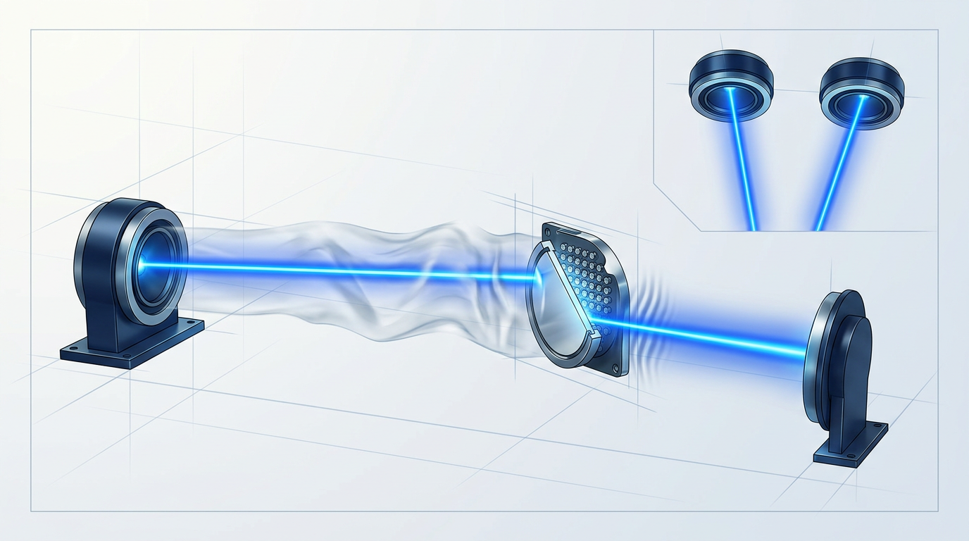
- Turbulence-induced scintillation: Refractive index fluctuations driven by temperature gradients produce two distinct effects: beam wander, where the entire beam shifts off the receiver aperture, and scintillation, where intensity fluctuates across the beam cross-section at the detector. Both degrade link margin and motivate adaptive optics and aperture averaging.
With those impairment classes in view, work through the mitigation toolkit systematically — starting with the techniques that address turbulence.
Turbulence mitigation: adaptive optics and aperture averaging
Apply adaptive optics (AO) to counteract the phase distortions turbulence imprints on the beam: a wavefront sensor — typically a Shack-Hartmann type — measures the aberrated phase across the pupil, and a deformable mirror or fast-steering mirror applies a conjugate correction in real time, recovering optical power that would otherwise be scattered out of the receiver's field.
The AO control loop must close faster than the turbulence coherence time, characterised by the Greenwood frequency — this bandwidth requirement sets the specification for your wavefront sensor readout rate and mirror actuator response.
AO is particularly critical on uplinks, where the beam traverses the full atmospheric column before any aperture can average out the accumulated distortion; on downlinks the geometry is reversed and the large ground aperture itself provides partial relief.
Note that the fast-steering mirror used in the AO correction loop shares hardware with the fine-tracking system covered in Step 6 — the two loops are closely related, though their control objectives differ.
Complement AO with aperture averaging: increasing the receiver aperture diameter collects light from multiple coherence cells of the turbulent beam simultaneously, and because intensity fluctuations across those cells are partially independent, the scintillation variance at the detector is reduced.
The aperture averaging factor quantifies this reduction and is a direct input to your link margin calculation. The technique is most effective on downlinks, where the beam is scrambled by the atmosphere before reaching the large ground aperture; on uplinks the beam is narrow at the transmitter end where scrambling begins, so aperture averaging provides less relief.
Diversity architectures: spatial and site diversity
Where turbulence mitigations recover power lost to phase aberrations, spatial diversity addresses the statistical problem of deep fades by ensuring that not all optical paths fail simultaneously.
Separate multiple transmit apertures by more than the atmospheric coherence length (the Fried parameter, r₀) so that each beam propagates through a statistically independent turbulence realisation — when one beam experiences a deep fade, the others are unlikely to fade at the same instant, and the combined received power remains more stable.
MIMO configurations extend this principle to both ends of the link, with multiple receive apertures decorrelating the received intensity in parallel with the transmit-side diversity. This is a system-architecture trade: hardware complexity increases, but so does the achievable availability.
For cloud opacity on ground-to-satellite links — where fog or cloud cover can block the path entirely — deploy site diversity: geographically separated ground stations with enough spacing that local weather patterns are statistically uncorrelated.
Site separations of tens to hundreds of kilometres are typically required to decorrelate cloud cover between stations; when one site is obscured, another maintains the link.
Forward error correction: quantifiable link margin
After the optical mitigations have done their work, residual fade events will still produce bit errors — address these with forward error correction (FEC), adding structured redundancy to the transmitted data stream so the receiver can reconstruct the original data through fade events that would otherwise cause uncorrectable errors.
Reed-Solomon, LDPC, and turbo codes each deliver a defined coding gain in dB that enters directly into your link budget as a real margin contribution — FEC is not a soft fallback but a hard engineering tool with a measurable number attached to it.
FEC operates at the transmit chain and link layer; Step 7 covers how the decoder at the receiver reconstructs the data stream from the redundancy-encoded signal.
A free-space optical system designed only for clear-sky conditions is not a deployable system — it is a clear-sky demonstration. Link availability is an engineering outcome set by the mitigation architecture: AO and aperture averaging manage turbulence, spatial and site diversity guard against fades and weather opacity, and FEC converts residual errors into recoverable events. Specify all layers together, not as optional add-ons.
Step 6
Acquire, point, and track the beam
Key Insights
PAT requires dedicated hardware.
Single-beam design eliminates misalignment.
Gimbal handles range; FSM handles precision.
FSO beams operate at divergence angles in the microradian-to-milliradian range, which means the beam footprint at satellite distances may span only tens of metres — and a pointing error of even a small fraction of the beamwidth produces measurable link margin loss.
For deep-space links, the required pointing accuracy falls below one microradian, a level that cannot be achieved through open-loop attitude knowledge alone — which is why pointing, acquisition, and tracking (PAT) is a dedicated engineering discipline with its own hardware stack.
The solution is a three-stage cascade that progressively narrows the pointing error from the initial open-loop uncertainty down to the sub-microradian regime needed for a stable data link.
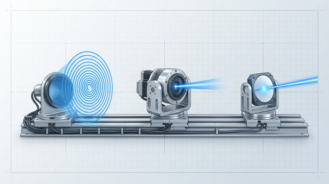
- Acquisition: One terminal — typically the ground station — scans the angular uncertainty region using a wide-divergence beacon in a raster or spiral pattern. The uncertainty region, set by open-loop pointing knowledge from inertial measurement units, star trackers, and ephemeris data, is typically in the 1–10 mrad range. The remote terminal detects the beacon and transitions to coarse tracking.
- Coarse tracking: A motorised gimbal rotates the telescope or transmit aperture to reduce the pointing error from open-loop uncertainty down toward the regime where fine tracking can take over. The gimbal provides a large angular range but has limited bandwidth and angular resolution.
- Fine tracking: A fast-steering mirror (FSM) closes a high-bandwidth servo control loop on the beacon signal, achieving sub-microradian pointing accuracy. The FSM operates over a small angular range but at high bandwidth — correcting residual errors and platform vibration faster than the gimbal can respond.
The gimbal and FSM are complementary: the gimbal handles coarse, large-angle corrections while the FSM handles fine, high-frequency corrections, forming a cascaded control architecture with demonstrated bandwidths of around 190 Hz for the cascaded loop and 350 Hz for the nested fine-tracking loop.
The beacon provides the pointing reference that makes closed-loop operation possible: the receiving terminal images the beacon onto a focal-plane detector — typically a quad-cell detector or position-sensitive array — which computes the centroid of the beacon spot, generates an angular error signal, and feeds that error to the FSM servo loop.
The loop continuously drives the FSM to null the error, keeping the beam centred on the detector — it is this closed-loop correction, rather than any reliance on open-loop pointing knowledge, that achieves sub-microradian accuracy.
The link establishment sequence is asymmetric: the ground station (with more power budget and a known position) initiates the scan; the remote terminal detects and returns a signal; then both pull into closed-loop fine tracking simultaneously.
Acquisition time is a real system design parameter — implementations have demonstrated reliable link acquisition in under 60 seconds, but the budget depends on scan pattern geometry, beacon power, and the size of the initial uncertainty region.
When the beacon and data beam travel on separate optical paths, any angular divergence between those paths introduces a pointing error the tracking loop cannot correct — the loop is locked on the beacon while the data beam is offset. Nesting the tracking tone within the data beam on a single amplified output eliminates this error class entirely: the tracking loop servos on the same beam that carries the data, so beacon-to-data alignment is guaranteed by construction. Look for this property when evaluating FSO system designs.
Pointing error has a direct consequence in the link budget: for a Gaussian beam, pointing loss scales with the square of the pointing error normalised to the beamwidth.
Maintaining tracking accuracy within roughly 10–20% of the beamwidth keeps pointing loss below approximately 1–2 dB — a meaningful fraction of total link margin, and the quantitative reason PAT performance must be specified alongside transmit power and aperture size when closing the link budget.
Step 7
Detect and decode the received signal

Key Insights
PIN suits strong signals; APD suits weak ones.
Coherent detection enables DSP-based turbulence mitigation.
The receiver's job is a chain of conversions: the incoming optical beam is collected through a receive aperture and focusing lens, concentrated onto a photodetector, converted from photons to electrical current, amplified and filtered, then decoded back into the original data stream.
PIN photodiodes: the baseline detector
A PIN photodiode operates through a reverse-biased p-i-n junction: incident photons generate electron-hole pairs in the intrinsic layer, producing a photocurrent proportional to the received optical power.
PIN detectors carry no internal gain, so sensitivity is set by thermal noise in the transimpedance amplifier (TIA) front-end — they are well-suited to shorter links and higher received power levels where that thermal noise floor is not the limiting factor.
Avalanche photodiodes: higher sensitivity through internal gain
Where received power is low, an avalanche photodiode (APD) provides internal multiplication gain through impact ionisation, amplifying the photocurrent before it reaches the TIA and improving sensitivity at the cost of added noise.
Higher APD gain amplifies the signal but also amplifies stochastic multiplication noise, quantified as the excess noise factor. The optimal gain point balances these two effects — simply running the APD at maximum gain degrades sensitivity rather than improving it. InGaAs APDs dominate the 1550 nm window used in most FSO systems.
The four principal noise sources that set the sensitivity floor in a direct-detection receiver are distinct in origin and each demands a different design response.
- Shot noise: Fundamental noise arising from the discrete, statistical arrival of photons at the detector. It sets the quantum limit on receiver sensitivity and cannot be reduced by circuit design.
- Thermal noise: Generated in the TIA front-end resistances. Reducible through careful circuit design and cooling, but never fully eliminated in direct-detection systems.
- Dark current noise: Reverse leakage current that flows through the junction even in the absence of light. A device-level parameter determined by material quality and operating temperature.
- Amplified spontaneous emission (ASE) noise: Present when an optical pre-amplifier is used upstream of the detector. ASE broadband noise beats against the signal and degrades the optical signal-to-noise ratio entering the detector.
For the most demanding links — highest data rates, longest ranges, or where turbulence-induced phase distortions must be corrected — coherent detection offers a fundamentally different and more capable receiver architecture.
In a coherent receiver, the incoming signal is mixed with a stable local oscillator (LO) laser in a 90-degree optical hybrid, recovering both the amplitude and phase of the received optical field — information that direct detection discards entirely.
This architecture suppresses thermal noise and drives performance toward the shot-noise limit, enabling the DPSK and QPSK modulation formats introduced at the modulation stage, which direct detection cannot recover.
Coherent receivers also open the door to digital signal processing (DSP) in the electrical domain, allowing turbulence-induced phase and amplitude distortions to be compensated after detection — a capability unavailable to IM/DD systems.
The trade-off is architectural complexity: a coherent receiver requires a narrow-linewidth, frequency-stable LO laser and more sophisticated signal processing hardware than a direct-detection front-end.
The electrical decoding path
From the detector output, the signal follows a defined processing chain before data is recovered.
- TIA amplification: The photocurrent from the detector is converted to a voltage and amplified by the transimpedance amplifier, raising the signal to a level suitable for further processing.
- Bandpass filtering: The amplified signal is filtered to the signal bandwidth, rejecting out-of-band noise before sampling.
- Analogue-to-digital conversion: The filtered analogue signal is sampled and digitised, producing a discrete-time representation of the received waveform.
- Clock-and-data recovery (CDR): The CDR circuit extracts the transmitter clock from the received signal and re-aligns the data to it, correcting timing jitter introduced across the link.
- Forward error correction (FEC) decoding: FEC — introduced in Step 5 as a link margin contribution against atmospheric fades — performs its final role here, correcting residual bit errors in the recovered bitstream.
- Recovered data output: The corrected bitstream is delivered to the network interface, completing the signal chain from photon arrival to usable data.
With the data recovered and errors corrected, the free-space optical link has fulfilled its purpose: a modulated laser beam, launched at the transmitter and carried through free space, has been faithfully converted back into the original data stream at the receiver.
Ready to Put the Architecture into Practice?
You have the full picture of how a free-space optical link works. See how our FSOC-specific EDFA technology fits into that architecture — from transmit amplification to link margin.
Conclusion
From laser source to decoded data
You now have a complete end-to-end picture of how a free-space optical link actually works — not as a list of components, but as a sequence of interdependent decisions that either hold together or don't.
That interdependence is the principle worth keeping: a closed FSO link is all margins holding simultaneously — transmit power, pointing accuracy, atmospheric mitigation, and receiver sensitivity each operating within its design window at the same time.
From here, the natural engineering questions shift outward: link availability planning, system integration, and standards compatibility are the territory that follows.
Frequently asked questions about free space laser communication
Practical answers on FSO range limits, interception risk, failure modes, and detection technology — for engineers and evaluators working through deployment decisions.
Range in free space optical communication is not a fixed property — it is a function of link budget, atmospheric conditions, and the availability target you are designing to. The same hardware will operate at very different effective distances depending on where it is deployed and what uptime is required. For carrier-class availability (99.999%, or less than five minutes of downtime per year) in non-desert, humid environments where fog is a regular occurrence, IEEE Spectrum research puts the practical single-link range at 200–500 metres. Longer terrestrial links of 1–5 km are achievable with spatial diversity architectures, higher transmit power, or in drier, clearer climates where fog attenuation is a less frequent constraint. Beyond the atmosphere, the picture changes entirely. LEO satellite links operate over hundreds of kilometres, GEO links over tens of thousands, and inter-satellite crosslinks span similar distances — all in an environment where fog and cloud are either absent or confined to a thin atmospheric layer. NASA's TBIRD mission demonstrated 200 Gbps downlinks from a LEO CubeSat, confirming that space FSO links are limited by geometry and link budget rather than weather. The key planning insight: specify your availability target and local climate first, then derive your maximum link length from those constraints — not the other way around.
FSO beams are substantially harder to intercept passively than RF signals, but they are not immune. The fundamental difference is geometry: an RF transmitter radiates in a wide pattern that can be received at any point within range without the legitimate receiver detecting anything unusual. An FSO beam is highly directional and geometrically narrow — it does not propagate beyond its intended path unless reflected or scattered, and intercepting it requires physical placement in the optical path between transmitter and receiver. That physical intrusion is detectable: the receiver's signal level would drop as the interception aperture diverts optical power, and the aperture itself would be visible in the beam corridor. The beam does not penetrate opaque objects. That said, the honest engineering position is that FSO is not uninterceptable. Atmospheric scattering from fog and haze does produce some off-axis light that propagates outside the main beam, and research has confirmed that a sophisticated adversary with appropriate equipment and physical access to the beam corridor could in principle attempt passive collection of this scattered light — particularly at distances from the beam waist where the beam has widened. The practical security advantage of FSO over RF is real and significant, but it is a matter of degree, not an absolute guarantee.
There is no single answer to this question without specifying the required data rate, available transmit power, aperture size, and atmospheric environment — because range and data rate trade off directly against each other through the link budget. At shorter terrestrial ranges, commercial FSO equipment routinely achieves multi-Gbps data rates; a field demonstration achieved 4 Tbps over a 1.8 km link using coherent wavelength-division multiplexing. At LEO satellite distances, NASA's TBIRD programme demonstrated 200 Gbps downlinks from a 6U CubeSat — the highest downlink rate achieved by any space platform at the time. At lunar distances (~400,000 km), NASA's LLCD mission achieved 622 Mbps downlink rates. As distance increases further toward Mars, data rates drop sharply: NASA's deep-space optical communication work targets rates on the order of 100 Mbps at closer Mars ranges, falling to hundreds of kilobits per second at maximum range — but even those rates outperform what RF systems can deliver at the same distances with comparable terminal mass and power. The governing rule: every 10 dB of additional link distance requires roughly 20 dB of compensating gain from aperture, transmit power, or receiver sensitivity to maintain the same data rate.
Cloud and fog opacity is the dominant cause of FSO link outage, both for terrestrial links and ground-to-satellite paths. Water droplets in clouds and fog scatter optical wavelengths through Mie scattering, imposing attenuation that can reach hundreds of dB per kilometre in dense conditions — far beyond what any practical link budget can overcome. These outages are temporary: the link recovers when the obscuration clears. This characteristic is the primary driver for site diversity architectures, where geographically separated terminals provide an alternative path when one site is obscured. Pointing loss is the second major failure mode. Wind loading on rooftop mounts, satellite attitude disturbances, thermal drift in optical alignment, or a tracking loop losing lock can all cause the beam to miss the receive aperture. Because FSO beamwidths are narrow, even small angular errors produce measurable link margin loss, and errors beyond roughly 10–20% of the beamwidth can cause outage. Solar background noise is a third failure mode: at certain sun angles, direct or reflected sunlight entering the receive aperture can saturate the photodetector, causing temporary link loss. This is mitigated through narrow-band optical filtering at the receiver and careful terminal orientation during installation.
Direct detection (also called intensity modulation / direct detection, or IM/DD) measures the intensity of the arriving optical signal. The photodetector converts incident photons to photocurrent proportional to optical power, and data is recovered from intensity variations — as in on-off keying (OOK). It is simpler, lower cost, and adequate for the majority of commercial terrestrial FSO deployments. Coherent detection mixes the received signal with a local oscillator laser in an optical hybrid before detection. This recovers both the amplitude and phase of the signal, enabling higher-order modulation formats such as DPSK and QPSK, and providing receiver sensitivity approaching the quantum (shot-noise) limit. The sensitivity advantage of coherent over direct detection is significant — on the order of 10–20 dB at equivalent data rates — which translates directly into longer achievable range or improved link margin under the same atmospheric conditions. Coherent detection also enables digital signal processing (DSP) at the receiver, which can partially compensate for turbulence-induced phase distortion, a capability NASA receiver research has identified as particularly valuable for links operating through the atmosphere. The trade-off is cost and complexity: coherent receivers require a stable local oscillator laser and a precise optical hybrid, making them substantially more expensive than direct-detection equivalents. In practice, direct detection suits most terrestrial FSO links; coherent detection is the right choice for the highest data rates, longest ranges, or where link margin is tight.