
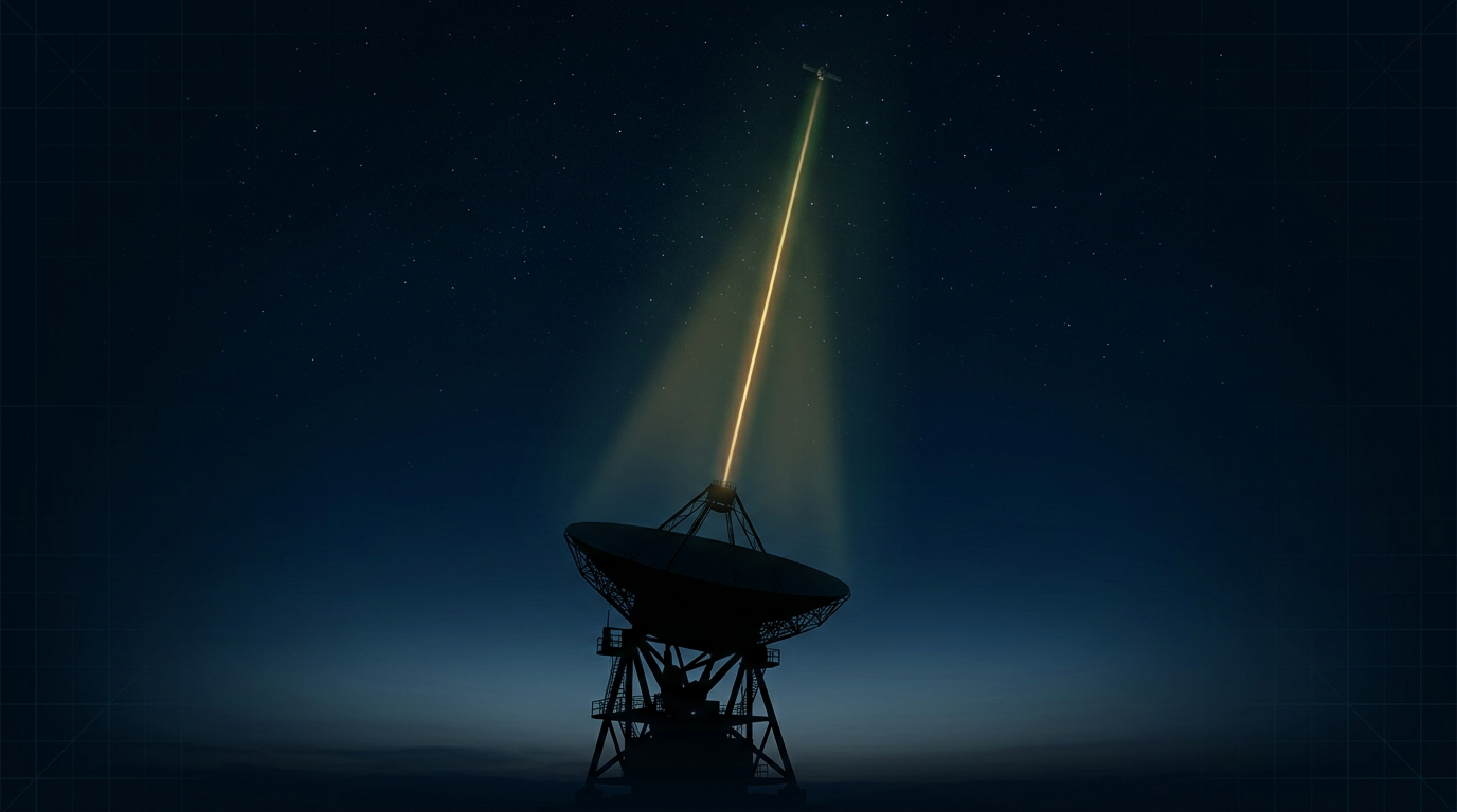
The Ground-Station Uplink Challenge in Free-Space Communication
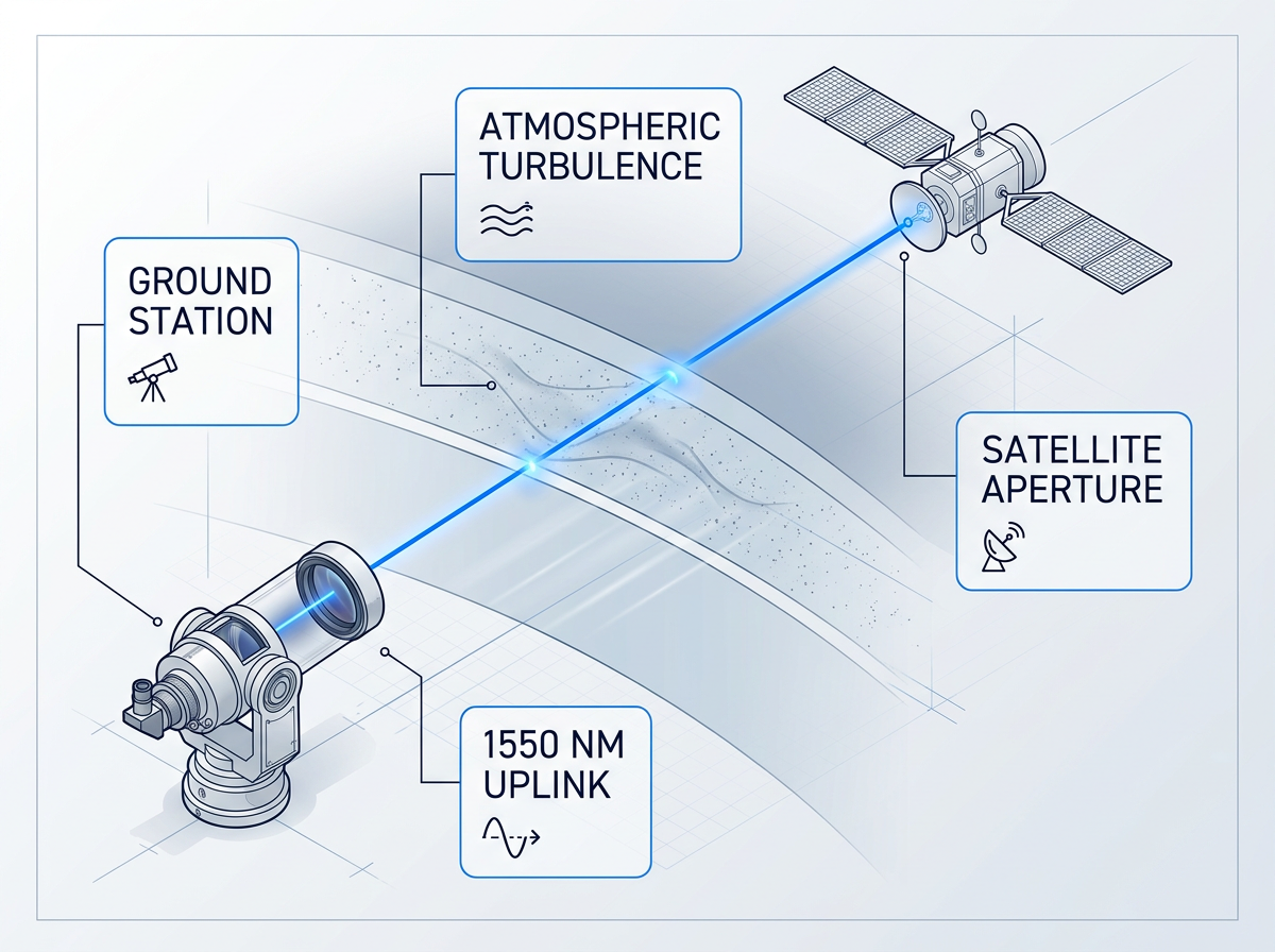
Optical ground links are already displacing congested RF spectrum as the path to high-throughput satellite connectivity. The uplink direction is the harder problem: atmospheric turbulence compounds across the full ground-to-satellite propagation path, not just the terminal segment as in the downlink. That asymmetry makes amplifier selection specifically consequential. Closing the link with adequate margin at 1550 nm, maintaining beam alignment through acquisition and tracking modes, and preserving compatibility across SDA, CCSDS, and proprietary protocols as standards evolve — these three tensions shape every optical ground-station uplink design.
Single-Beam Beacon and Data: One Alignment Path
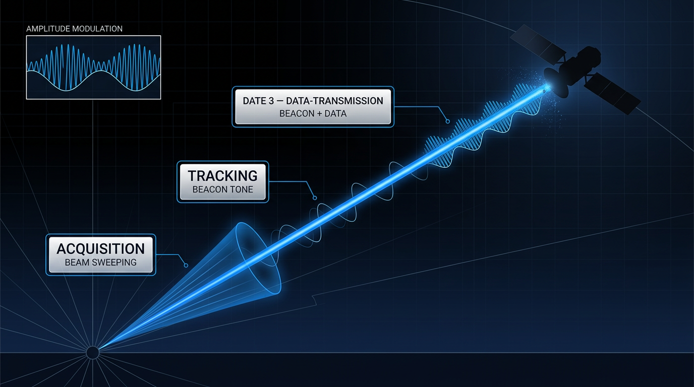
Conventional FSO ground-link designs use separate beacon and data beams — two hardware paths, two alignment mechanisms, twice the failure modes. A cleaner architecture nests both in one amplified beam: amplitude modulation carries the tracking beacon at low depth, with the data signal riding above it from a single module.
Three operating modes structure this across the full link session. Acquisition mode establishes initial lock with the satellite. Tracking mode keeps the link stable via the beacon. Data-transmission mode carries the uplink while the beacon continues alongside — in the same beam, on the same alignment path.
10 W at 1550 nm: Output Power and Beam Quality
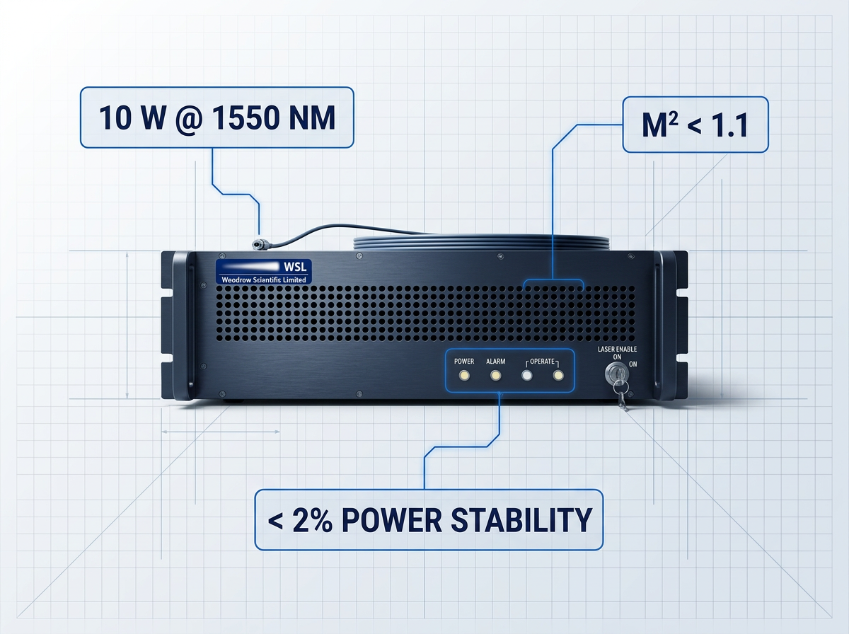
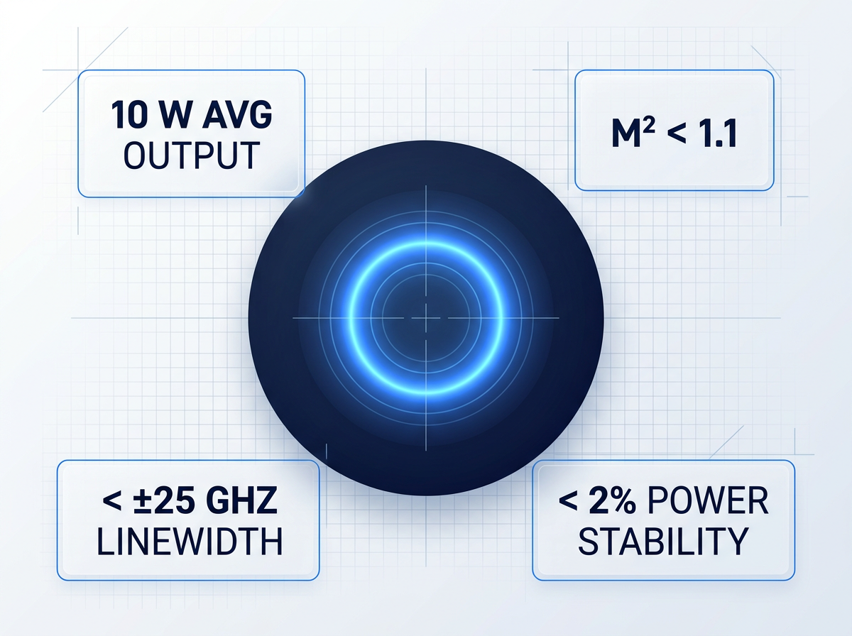
At M² < 1.1, the output is near diffraction-limited — minimising beam divergence across kilometre-scale propagation paths and maximising received power at the satellite aperture. This is the specification engineers reach for first when closing an FSO link budget.
Average output is 10 W at 1550 nm, with full 0–100% power control and < 2% power stability. That stability figure matters as much as the peak: a consistent 10 W holds link margin where an unstable higher figure cannot. Higher output power is available on request.
Modulation-on-Demand: Software-Definable Operation as Standards Evolve
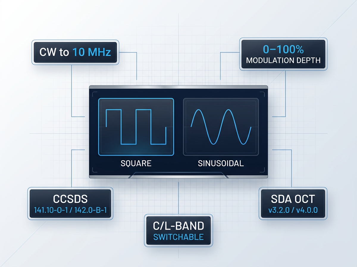
The FSO standards landscape is not settled. SDA OCT v3.2.0 and v4.0.0 are both in active deployment; CCSDS 141.10-O-1 and 142.0-B-1 run alongside proprietary protocols — all continuing to evolve. A fixed-function amplifier locks a programme to today's standard.
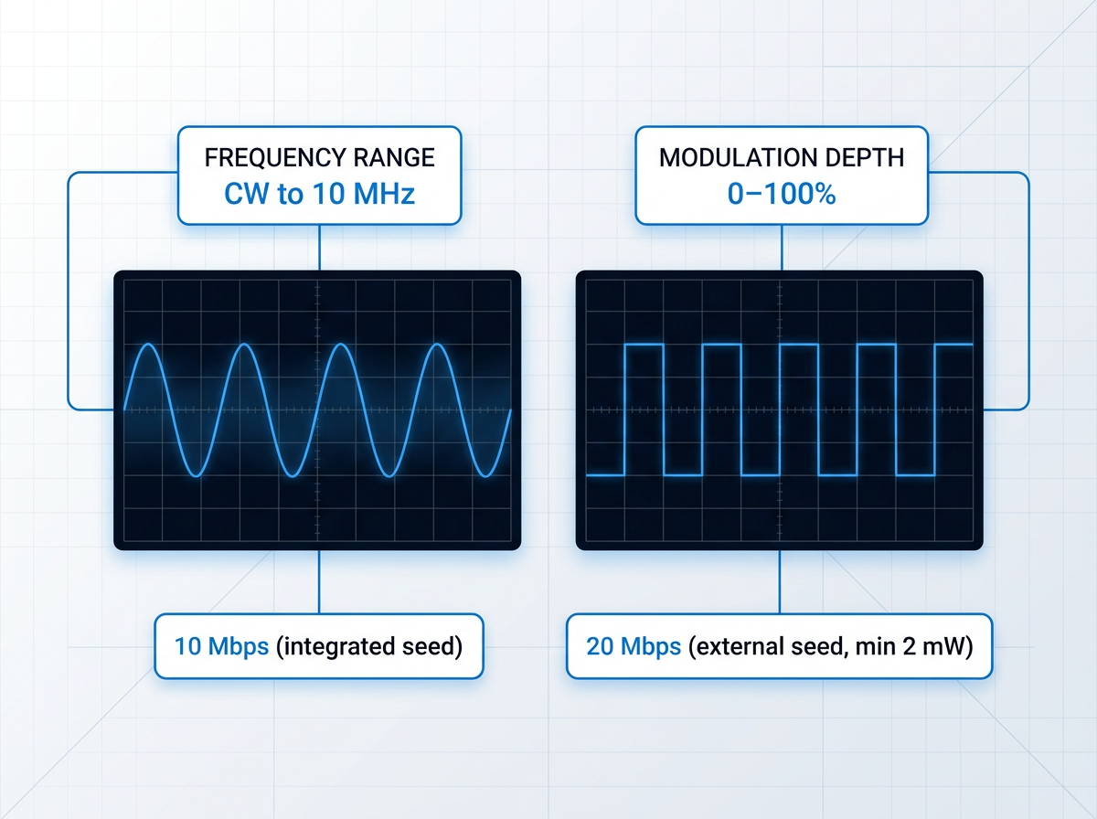
Modulation-on-Demand resolves this directly: software-selectable square or sinusoidal waveforms, frequency from CW to 10 MHz, modulation depth 0–100%, switchable to CCSDS or SDA at full power across C/L-band. The same hardware configures as beacon-only, uplink amplifier, or both. With ±2 nm tunability (ITU-T G.694 compatible), the amplifier stays aligned to standards as they mature.
C-Band, L-Band, or Dual
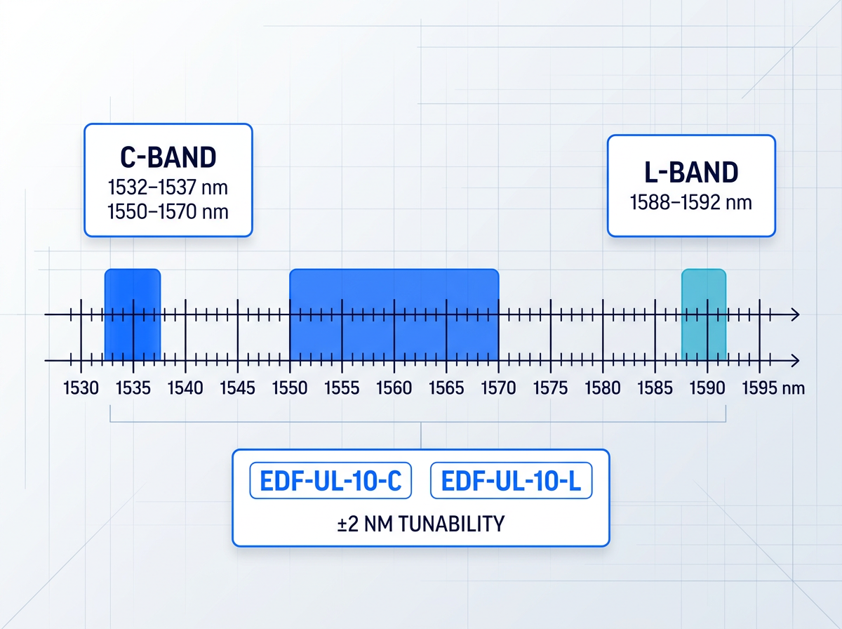
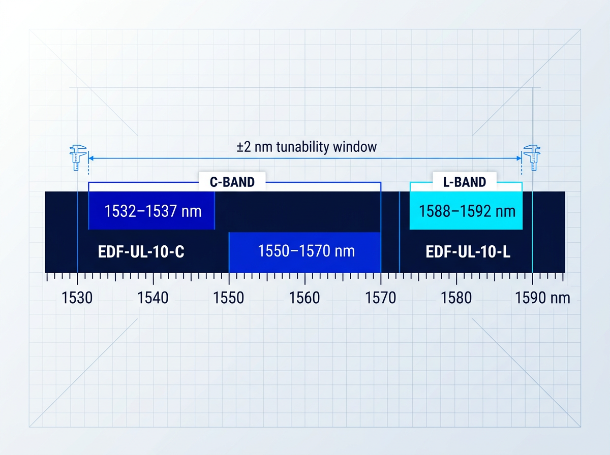
Band selection is a first-order architectural decision, specified per programme. EDF-UL-10-C covers C-band seed ranges of 1532–1537 nm and 1550–1570 nm; EDF-UL-10-L covers L-band at 1588–1592 nm. Dual-band operation is available from a single source.
Standard ±2 nm tunability around the seed wavelength supports SDA channel grid alignment; broader tunability is available on request. The amplifier is built to your programme's band requirement — not reconfigured post-purchase.
2- and 4-Emitter Array Support
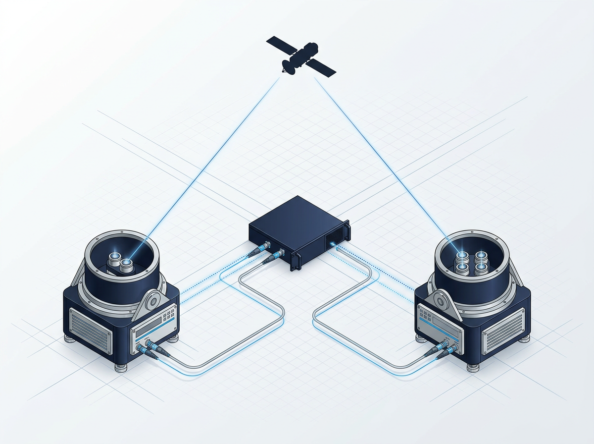
The amplifier is configured to support 2- and 4-emitter arrays, with multi-station synchronisation built into the hardware — no additional synchronisation equipment required.
This directly enables site-diversity and emitter-diversity architectures at the hardware level. Synchronisation across emitters and stations is a native capability, not an integration task left to the system architect. Section 8 covers the network architecture in full.
Amplify Third-Party Transmitters
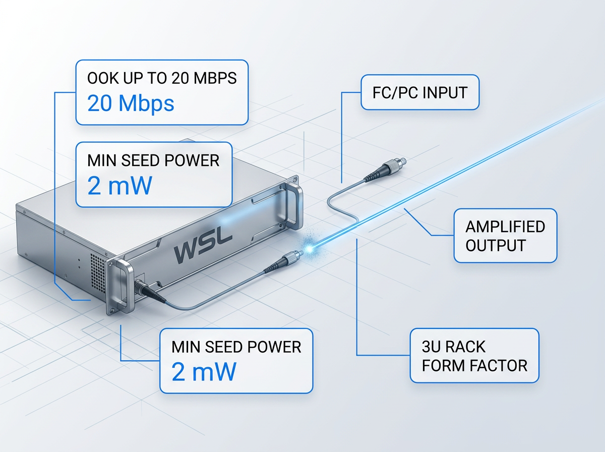
Ground stations with existing transmitter hardware do not need to replace it. The amplifier accepts an external optical seed via FC/PC input, supporting OOK up to 20 Mbps with a minimum seed power of 2 mW.
This makes the WSL amplification stage a direct integration point for third-party transmitters already deployed in your architecture — preserving existing hardware investment while adding high-power amplification at 1550 nm.
Separate Amplifier from Aperture
Standard fibre delivery cable is 10 m with an FC/PC output and integrated optical isolation. Longer runs are available on request. This allows the amplifier unit to be rack-mounted away from the telescope aperture — a common requirement in ground-station designs where the amplifier lives in a separate equipment enclosure.
Optical isolation at the output protects the amplifier from back-reflections entering through the delivery fibre, a practical design detail for installations where the output path may not be perfectly terminated at all times.

Standard 3U Rack, Three Interfaces
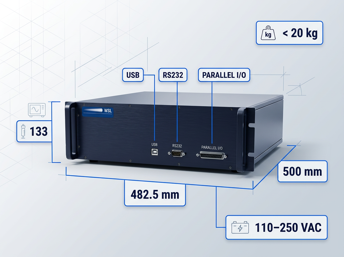
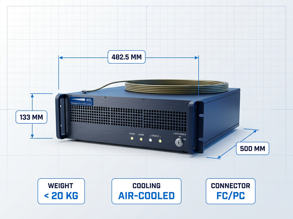
The amplifier occupies a 3U 19" rack (482.5 × 500 × 133 mm, <20 kg), runs on 110–250 VAC at under 250 W, and is air-cooled. Wide power supply compatibility removes the need for site-specific power conditioning.
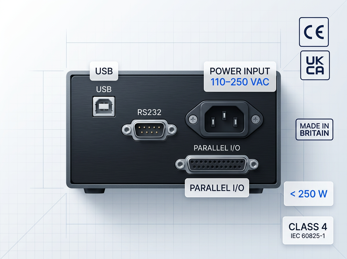
Control interfaces cover three architectures: USB and RS232 for software-driven operation, Parallel I/O for automated and real-time control paths. CE and UKCA certified. Full specifications are in the table below.
Optical Performance
Average output power: 10 W (higher available on request) · Beam quality (M²): < 1.1 · Output linewidth: < ±25 GHz · Power control range: 0–100% · Power stability: < 2%
Wavelength and Band
C-band (EDF-UL-10-C): 1532–1537 nm and 1550–1570 nm · L-band (EDF-UL-10-L): 1588–1592 nm · Wavelength tunability: ±2 nm standard; broader range available on request
Modulation and Data
Tracking/beacon frequency: CW to 10 MHz · Waveforms: sinusoidal or rectangular · Modulation depth: 0–100% · Uplink data rate (integrated seed): OOK up to 10 Mbps · Uplink data rate (external seed): OOK up to 20 Mbps; minimum external seed power 2 mW
Physical Specifications
Form factor: 3U 19" rack · Dimensions (W × D × H): 482.5 × 500 × 133 mm · Weight: < 20 kg · Cooling: air-cooled · Fibre delivery: 10 m standard cable (longer on request) · Output connector: FC/PC with optical isolation
Electrical, Interfaces, Certifications
Power supply: 110–250 VAC · Power consumption: < 250 W · Interfaces: USB, RS232, Parallel I/O · Laser class: Class 4 (IEC 60825-1) · Certifications: CE and UKCA · Manufacture: Made in Britain
Get the Full EDF-UL-10 Specification Sheet
All optical, modulation, mechanical, and interface parameters in one document. Download the official datasheet or explore the broader range of configurable EDFA platforms.

Site-Diversity and Multi-Emitter Network Architecture
Cloud cover remains the primary availability constraint for optical ground links. Diversity architectures — geographically distributed stations operating as a coordinated network — are the standard engineering response, and this amplifier platform is built to serve as the building block for them.
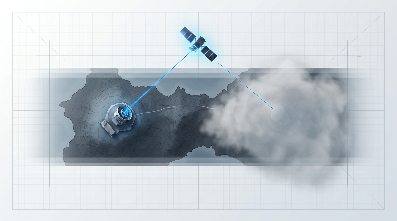
Cloud Cover Demands Geographically Distributed Ground Stations
Dispersed ground stations maintain link availability when cloud blocks any single site.

Native 2- and 4-Emitter Array Support, Synchronisation Built In
Multi-station synchronisation is built into the platform — no additional synchronisation hardware required.
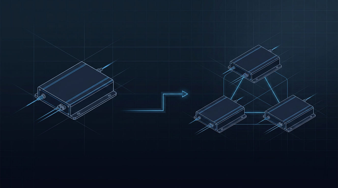
One Platform Scales from Single Station to Diversity Network
The same amplifier platform is multi-station diversity network compatible — no separate product required.
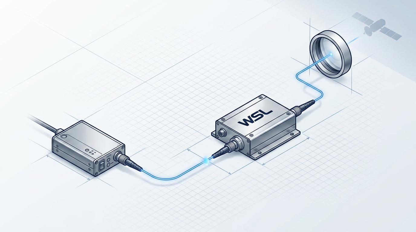
External Optical Input for Heterogeneous Network Integration
Accepts third-party transmitters via OOK to more than 10 Gbps; minimum seed power 2 mW.
Application Contexts: Where This Amplifier Is Deployed
From satellite optical ground stations to broader high-power erbium-fibre amplification programmes, these are the primary deployment contexts — with WSL able to configure the platform for requirements beyond those listed.

Optical Ground Station Integrators
WSL supplies this amplifier directly to OGS integrators building ground-station infrastructure. End-to-end hardware and software configurability makes it a fit for system-level component decisions.

FSOC High-Throughput Free-Space Links
High-data-rate optical links through free space, where high-power 1550 nm amplification is the enabling component. Satellite uplinks are one application within this broader category.
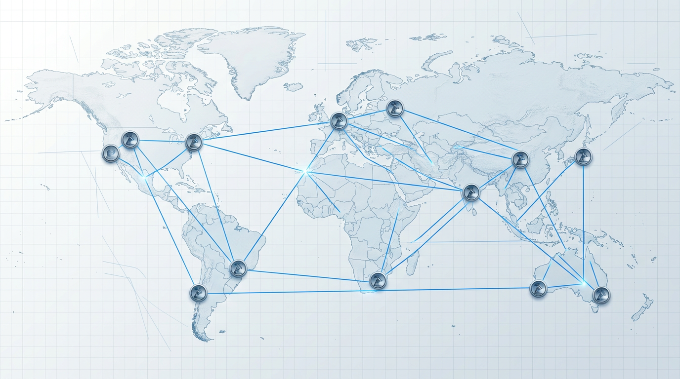
Site and Emitter Diversity Architectures
Built-in 2- and 4-emitter array support with multi-station synchronisation confirms fit for coordinated diversity network deployments without additional synchronisation hardware.

Wider High-Power Erbium-Fibre Amplification Programmes
Any programme requiring high-power, eye-safe erbium-fibre amplification. WSL can build and tailor an EDFA to a programme's specific requirements across hardware and software.
UK Manufacturer: In-House Design, Build, Qualification, and Support
Much of the EDFA supply market is resellers and importers — support is mediated, customisation is limited, and no one can fix what they did not design. WSL designs, builds, qualifies, and supports its amplifiers entirely in-house in the UK, on patented technology, with direct access to the engineers who built it.
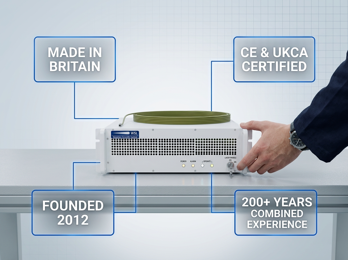
Expertise rooted in Southampton's Optoelectronics Research Centre — the birthplace of the EDFA — and backed by 200+ years of combined engineering experience. Hardware and Modulation-on-Demand software are both configured to your ground station, not adapted from a catalogue spec. CE and UKCA certified, Made in Britain.
Specify Your Uplink Amplifier: Start the Configuration Conversation
Pricing is quoted per configuration — the amplifier is built to your ground-station spec. Share your band, output power, modulation standard, emitter configuration, and integration constraints, and WSL will respond with a configuration proposal.

Frequently Asked Questions
Practical answers on amplifier compatibility, data rates, the single-beam architecture, and site-diversity fit — plus broader context on free-space optical technology and its role in telecom infrastructure.
The amplifier supports CCSDS optical HDR 1550 nm standard 141.10-O-1 and coding standard 142.0-B-1, SDA OCT v3.2.0 and v4.0.0, and proprietary standards. All are switchable via Modulation-on-Demand without any hardware replacement — the programme is not locked to the standard current at time of procurement.
Yes. The amplifier accepts a third-party transmitter seed via its external optical input port (FC/PC connector), amplifying it via OOK to more than 10 Gbps with a minimum seed power of 2 mW. Existing transmitter hardware does not need to be replaced — the amplifier sits downstream and boosts the seed to full output power.
With the integrated seed, the amplifier supports uplink data rates of up to 10 Mbps OOK. With an external seed input (minimum 2 mW via FC/PC), this rises to more than 10 Gbps OOK. Both configurations are available — which figure applies depends on whether you are using the amplifier's integrated seed or driving it from a third-party transmitter.
Amplitude modulation nests the tracking beacon at low modulation depth and the data signal above it — both carried in one amplified beam from a single module. The amplifier operates across three modes that map directly to the stages of an FSO link session: Acquisition mode for initial lock, Tracking mode for link maintenance, and Data-transmission mode for uplink data with the beacon riding alongside. One module serves all three roles sequentially, with no beam switching or separate hardware path required.
Yes. The amplifier natively supports 2- and 4-emitter arrays with multi-station synchronisation built in — no additional synchronisation hardware is required. It is multi-station diversity network compatible as a single platform. The external optical input also allows third-party transmitters to be integrated into a heterogeneous diversity network, which is relevant for programmes building across mixed hardware architectures.
Pricing is quoted per configuration — there is no catalogue price. WSL configures both the hardware (band, output power, emitter array, cooling, interfaces) and the software (Modulation-on-Demand, waveform, modulation standards) to the specific ground-station requirement. The starting point is to share your programme requirements with WSL, who will respond with a configuration proposal tailored to your architecture.
FSO (free-space optical) technology transmits data using modulated laser light propagating through free space — air or vacuum — rather than through fibre optic cable or RF spectrum. Operating at 1550 nm, it delivers high-bandwidth, licence-free connectivity with no spectrum allocation required. FSO is increasingly the preferred architecture for satellite-to-ground links and inter-satellite links, where data-rate demands exceed what RF can practically carry, as well as for high-throughput terrestrial wireless backhaul where laying fibre is not viable.
In telecom, FSO is the optical wireless layer — high-throughput, licence-free, and increasingly central to both satellite and terrestrial infrastructure. For satellite operators, FSO provides the ground-link and inter-satellite capacity that RF spectrum can no longer support at scale: unlicensed, high-data-rate, and unaffected by RF congestion. In terrestrial networks, FSO serves as high-capacity wireless backhaul and last-mile connectivity where fibre deployment is impractical. As satellite constellation data rates continue to grow, FSO ground links are becoming a standard infrastructure component rather than a specialist application.