

Introduction
This guide is written for engineers, technical evaluators, and advanced students working with or specifying optical communications systems.
Optical signals attenuate as they travel, and without amplification, the global fibre networks we rely on would not be viable at scale.
Fibre optic amplifiers are the technology that changed that reality — understanding them properly means understanding both the physics behind the gain and the trade-offs that determine which type belongs in which system.
By the end, you will have a clear picture of how optical amplification works, why distinct amplifier families exist, and how to evaluate them against real deployment requirements.
The guide moves from foundational physics through each major technology family, then into the performance parameters and practical considerations that matter when a specification is in front of you.
TL;DR
The choice of fibre optic amplifier is never arbitrary — each type exists because of specific physics, and each trade-off has real consequences for system performance.
Understanding why those differences exist is what separates a well-specified link from one that causes problems at commissioning or scale.
This article covers:

The physics behind optical gain explained
Amplifier types compared with use cases
Key performance parameters and engineering trade-offs
Deployment contexts across long-haul, metro, and FTTH
How to specify and source an amplifier
What is a Fiber Optic Amplifier?
A fiber optic amplifier is a device that boosts the power of an optical signal while keeping it entirely within the optical domain — no conversion to electricity, no retransmission, no regeneration. The signal goes in weak; it comes out stronger, still as light, still carrying exactly the data it was carrying before.
That all-optical nature is not a technical footnote — it is the defining characteristic that separates fiber optic amplifiers from everything that came before them, and the reason they became foundational to modern long-haul communications.
To understand why that matters, consider the problem they were built to solve. Light attenuates as it travels through silica fibre — a physical inevitability rooted in scattering and absorption losses within the glass itself. Over tens or hundreds of kilometres, a signal that started strong can become too weak to detect reliably.
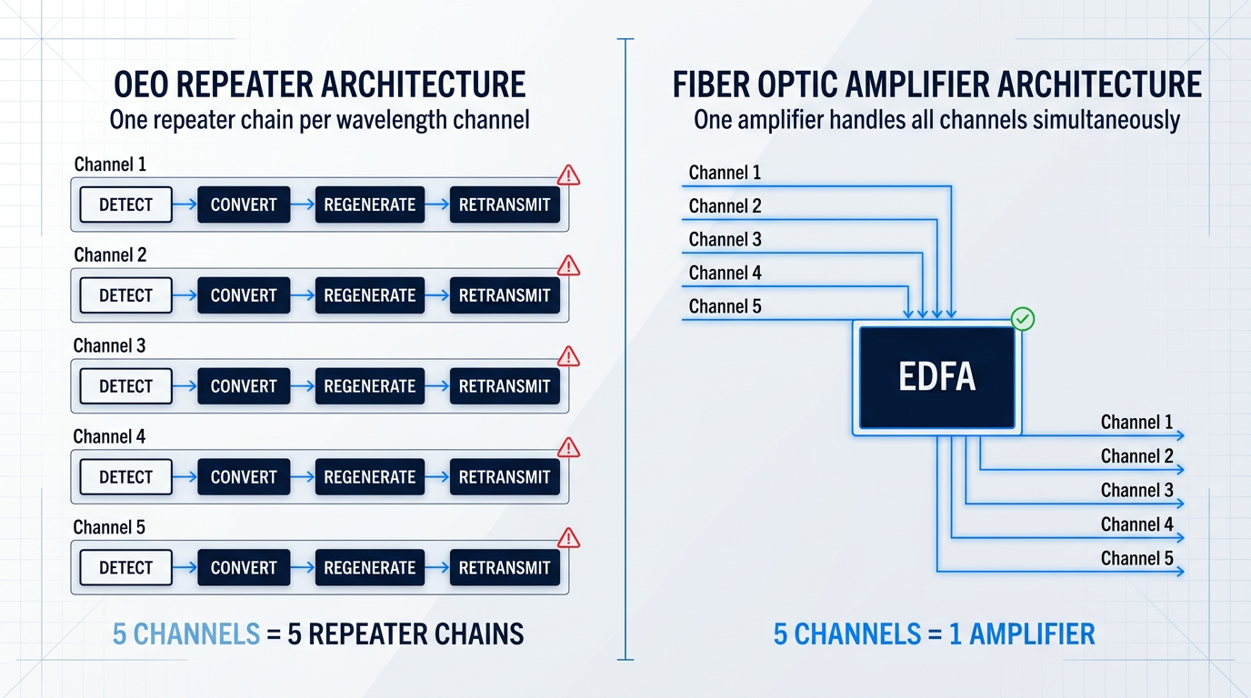
Before optical amplifiers existed, the standard solution was optical-electrical-optical (OEO) regeneration: a repeater would detect the incoming optical signal, convert it to an electrical signal, clean it up, and retransmit it as a fresh optical pulse. The signal was effectively recreated from scratch at each repeater node.
OEO regeneration worked, but it carried a structural limitation that became increasingly painful as network capacity demands grew. Each repeater could only process a single wavelength channel — it was inherently tied to the modulation format and bit rate of that one channel.
In a wavelength-division multiplexing (WDM) system, where dozens or even hundreds of wavelength channels share the same fibre simultaneously, this created a direct hardware scaling problem: one repeater per channel, per span. A 100-channel WDM link required 100 parallel repeater chains, each one independent, each one adding cost, complexity, and a potential failure point.
An OEO repeater processes one wavelength channel at a time. A fiber optic amplifier processes all channels simultaneously — the amplifier count stays constant regardless of how many channels the fibre carries.
A fiber optic amplifier sidesteps this scaling problem entirely. Because amplification happens in the optical domain, the device boosts every wavelength channel passing through it at the same time, without any awareness of — or dependence on — the modulation format or data rate of any individual channel.
Adding more WDM channels to a link does not require adding more amplifiers. The same amplifier that handles 40 channels handles 80 or 160 channels with equal indifference, provided those channels fall within its gain bandwidth. This is the engineering shift that made high-capacity, long-distance optical networking economically viable.
Four distinct technology families have emerged to deliver optical amplification, each exploiting a different physical mechanism: the erbium-doped fibre amplifier (EDFA), the Raman amplifier, the semiconductor optical amplifier (SOA), and the optical parametric amplifier. Subsequent sections of this guide examine each family in depth.
Of these, the EDFA became the dominant technology for long-haul and dense wavelength-division multiplexing (DWDM) systems — not by accident, but because erbium's natural gain band happens to coincide with the lowest-loss transmission window in standard silica fibre. That alignment is worth understanding in detail, and it is the subject of the EDFA section that follows.
The functional case for optical amplification is straightforward enough. What is considerably more interesting is the physics that makes it possible — specifically, how a length of doped fibre or a semiconductor chip can add energy to a passing optical signal without first converting that signal to something else. That question takes us into the underlying mechanics of optical gain.
How Fiber Optic Amplifiers Work: The Physics of Optical Gain
Every fiber optic amplifier performs the same essential trick: it adds energy to a light signal without ever converting that signal into an electrical current. Understanding how this is physically possible requires stepping inside the gain medium itself, where individual atoms interact with photons in a precisely governed way.
The fundamental mechanism is stimulated emission. When a photon at the correct frequency encounters an atom already in an excited energy state, it can trigger that atom to release a second photon — one that is coherent with the incoming photon, meaning it shares the same frequency, phase, polarisation, and direction of travel.
This coherence is what makes stimulated emission useful for amplification rather than merely illumination. The new photon is not a random addition to the light field; it is an identical copy of the signal photon, preserving the signal's modulation and information content exactly. Contrast this with spontaneous emission, where an excited atom decays on its own schedule, releasing a photon in a random direction with a random phase — contributing noise rather than signal.
Population Inversion: The Prerequisite for Net Gain
Stimulated emission only produces net gain when it dominates over absorption — and that requires a specific condition in the gain medium. Under thermal equilibrium, the ground state is always more heavily populated than excited states, governed by the Boltzmann distribution. A medium in this natural condition will absorb signal photons rather than amplify them.
To flip this, the gain medium must be driven into population inversion: a non-equilibrium state in which more atoms occupy the excited level than the ground state. This is the role of the pump laser — it continuously drives atoms upward into excited states faster than they spontaneously decay, sustaining the inverted population against the pull of thermal equilibrium.
Pump Absorption and the Metastable Level
The abstract process becomes concrete in a rare-earth doped fibre. Taking erbium as the example — appropriate here, since the EDFA section follows immediately — pump laser light at either 980 nm or 1480 nm is launched into the erbium-doped fibre core. These pump photons are absorbed by erbium ions (Er³⁺), exciting them from the ground state to higher energy bands.
Ions excited to the upper pump band do not remain there long. They undergo rapid, non-radiative decay down to a lower energy level — the ⁴I₁₃/₂ metastable level — where they accumulate and persist for a comparatively long time, on the order of milliseconds. This extended metastable lifetime is what makes erbium so effective: the level acts as a reservoir of primed ions, continuously replenished by the pump and available to be triggered by arriving signal photons.
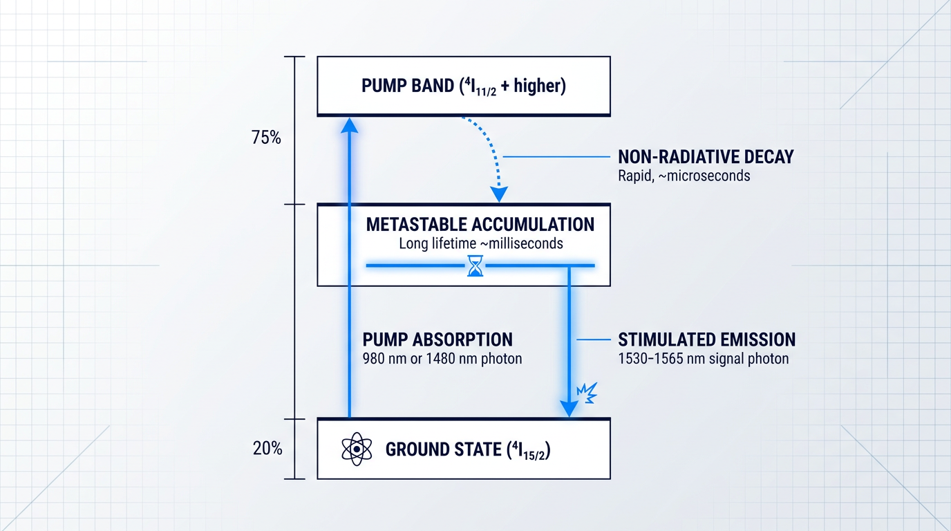
When a signal photon in the 1530–1565 nm wavelength range arrives, it interacts with an ion sitting in the metastable level and triggers stimulated emission: the ion drops to the ground state and releases a coherent copy of the signal photon, amplifying the optical field without any electrical conversion.
Amplified Spontaneous Emission and the Noise Floor
Population inversion does not only enable stimulated emission — it inevitably produces spontaneous emission as well. Excited ions decay at random, releasing photons in arbitrary directions and with arbitrary phases across the gain bandwidth.
A fraction of these spontaneously emitted photons happen to travel along the fibre axis and are themselves amplified by the gain medium. This is amplified spontaneous emission (ASE), and it is an unavoidable companion to optical gain: every amplifier that achieves population inversion will also generate ASE, which sets a fundamental noise floor that no design choice can eliminate entirely.
Population inversion is simultaneously the origin of optical gain and the origin of ASE noise. The two are physically inseparable — which is why every amplifier design involves trade-offs between gain, noise figure, and output power rather than optimising each independently.
The engineering consequences of ASE — how it accumulates in cascaded amplifier chains, how it is quantified through noise figure, and how it constrains optical signal-to-noise ratio — are examined in the performance parameters section later in this guide.
Four Gain Mechanisms: A Conceptual Map
The four amplifier families covered in this guide each exploit a distinct physical mechanism, with different implications for gain bandwidth, noise characteristics, deployment context, and form factor.
- EDFA: Rare-Earth Stimulated Emission: Pump photons excite erbium ions in a doped fibre; signal photons trigger stimulated emission from the metastable level, producing coherent optical gain.
- Raman: Nonlinear Scattering in the Fibre: Pump photons interact with molecular vibrations (optical phonons) in the silica glass itself, transferring energy to signal photons at a longer wavelength. No dopant required.
- SOA: Semiconductor Carrier Recombination: Electrical current injection creates electron-hole pairs in a semiconductor gain medium; signal photons trigger their recombination, producing stimulated emission without an optical pump.
- OPA: Parametric Four-Wave Mixing: Pump photons interact with signal photons via the fibre's third-order nonlinearity, generating gain through a phase-sensitive parametric process without population inversion.
Each mechanism produces optical gain without converting the signal to the electrical domain, but the physical process, gain medium, and pump type differ fundamentally — and those differences drive every engineering trade-off explored in the sections that follow.
Of the four, the EDFA has proved the most consequential for long-haul optical communications, and the physics just covered explains why: erbium's long metastable lifetime and its gain band's alignment with low-loss transmission windows gave it a decisive advantage. The next section examines those spectral properties in detail and explains how they shaped the modern DWDM network.
Erbium-Doped Fibre Amplifiers (EDFAs)
The reason erbium became the dominant dopant for optical amplification is not historical accident — it is physics: the Er³⁺ ion's primary radiative transition emits directly into the minimum-loss transmission window of silica fibre, making it the only rare-earth dopant that was ever going to win this particular engineering contest.
That transition — from the ⁴I₁₃/₂ excited state to the ⁴I₁₅/₂ ground state — produces emission in the 1530–1565 nm range, which coincides precisely with the lowest attenuation window of silica glass (approximately 0.20 dB/km at 1550 nm for standard single-mode fibre).
The C-Band and L-Band Gain Windows
The C-band (1530–1565 nm), also called the conventional band or "erbium window," is where C-band EDFAs provide their highest gain and where the vast majority of long-haul DWDM deployments operate — the gain spectrum peaks near 1532 nm and delivers strong, usable gain across the full 35 nm window.
The L-band (1565–1625 nm) extends capacity beyond the C-band using the same Er³⁺ dopant: by operating at lower population inversion levels and using longer erbium-doped fibre lengths, L-band EDFAs provide gain across a further 60 nm, and are deployed in high-traffic metro and submarine systems where C-band capacity is fully subscribed.
Inside an EDFA: Component Structure
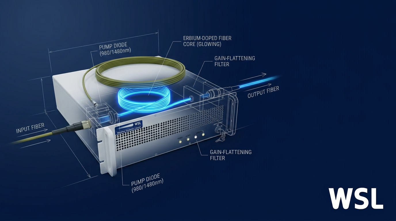
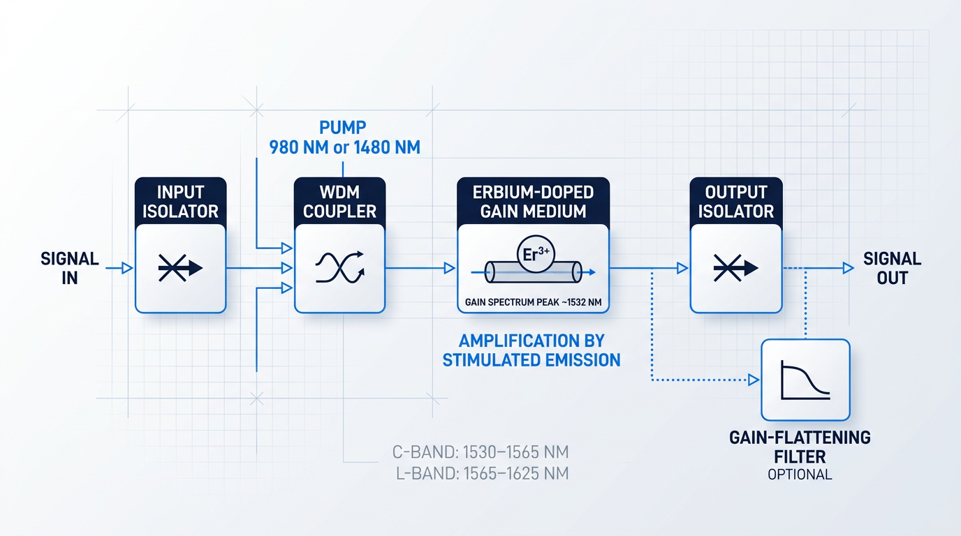
A practical EDFA is an engineered assembly of five core elements, each with a defined role in the amplification chain.
- Erbium-doped fibre: The gain medium — a short length of silica fibre with Er³⁺ ions in the core, where stimulated emission amplifies the signal.
- Pump laser diodes: Operate at 980 nm or 1480 nm; supply the optical energy that drives population inversion in the erbium ions.
- WDM coupler: Combines the pump and signal wavelengths onto a single fibre path so both enter the erbium-doped gain region together.
- Optical isolators: Placed at the input and output to suppress back-reflections that would destabilise the amplifier or cause unwanted lasing.
- Gain-flattening filter: An optional but common element in WDM deployments; equalises signal powers across channels by attenuating the gain-peak region.
The signal enters through the input isolator, is combined with pump light at the WDM coupler, traverses the erbium-doped fibre where it is amplified by stimulated emission, and exits through the output isolator — each component playing a non-negotiable engineering role in the chain.
Gain Flattening in WDM Systems
The Er³⁺ gain spectrum in silica is inherently non-uniform: it peaks near 1532 nm and rolls off toward longer wavelengths, meaning channels at different positions across the C-band receive different amounts of gain from a single amplifier stage.
In a WDM system carrying dozens or hundreds of channels, this per-stage gain variation compounds through each successive amplifier: channels near the gain peak accumulate more amplification than edge channels, consuming the OSNR budget unevenly and creating large channel-power differentials that degrade system performance.
A gain-flattening filter (GFF) is inserted — typically between amplifier stages in a dual-stage design — to impose a complementary loss profile that equalises channel powers across the band before the signal cascades further; without it, WDM systems cannot meet the tight gain-uniformity specifications required for reliable multi-span operation.
Why EDFAs Dominate DWDM
The decisive economic and engineering argument for EDFAs in DWDM systems is straightforward: a single EDFA simultaneously amplifies every wavelength channel within its gain window, with no dependence on channel count.
A single EDFA amplifies every WDM channel in its gain window simultaneously. An OEO repeater handles one wavelength — so a 100-channel DWDM system needs 100 parallel OEO chains per repeater site. One EDFA replaces all of them. This is the engineering reason EDFAs made the modern internet economically viable.
As Robert Mears — who first demonstrated optical gain in an erbium-doped fibre in 1985 — noted, the EDFA allowed multiple wavelength carriers to be simultaneously amplified, increasing bandwidth by more than three orders of magnitude compared to the electronic repeater systems it replaced, while keeping signals optical over intercontinental distances of thousands of kilometres.
Pumping Configurations and Trade-offs
The choice between 980 nm and 1480 nm pump wavelengths is a genuine engineering decision that depends on where in the amplifier cascade a given EDFA sits and which performance parameter — noise figure or output power — is the dominant constraint.
980 nm pumping drives erbium ions from the ground state (⁴I₁₅/₂) into the ⁴I₁₁/₂ level, from which they rapidly relax to the metastable ⁴I₁₃/₂ gain level; this three-level process produces a higher population inversion and a lower noise figure, making 980 nm the preferred choice for preamplifier stages where noise is the dominant concern.
1480 nm pumping drives transitions directly into the upper manifold of the gain level; this two-level process is less efficient for achieving low noise figures but delivers higher output power and better power-conversion efficiency, making it the preferred choice for booster (power amplifier) stages where launched power matters more than noise.
Hybrid forward/backward pumping — typically a 980 nm pump co-propagating with the signal through the first stage and a 1480 nm pump counter-propagating through the second — combines the low noise figure of 980 nm excitation with the high output power of 1480 nm conversion, and is the configuration of choice in demanding long-haul applications where both parameters must be controlled simultaneously.
EDFAs Beyond Telecommunications
The 1530–1625 nm window has become the platform of choice for a growing convergence of photonics applications beyond telecom: LiDAR, free-space optical communications (FSOC), quantum sensing, defence, and remote sensing all increasingly specify erbium-fibre amplification.
The engineering rationale is the same combination of properties that made EDFAs dominant in telecom: high output power, excellent beam quality, and a wavelength that is substantially safer for the eye than legacy 1064 nm sources — at 1550 nm, the interior of the eye becomes opaque, so the beam cannot reach the retina, allowing laser safety standards to permit significantly higher output powers than at 905 nm or 1064 nm wavelengths.
Woodrow Scientific Limited's Custom EDFA is a concrete example of how this engineering is realised end-to-end for demanding, non-telecom applications: every parameter is configured to the specific use case — operating band (C-band, L-band, or dual C+L), output power, pulse regime (CW, short-pulse at 100–500 ns, or custom), pulse energy, peak power, cooling (air or water), delivery cable, form factor, and control firmware.
Woodrow Scientific Limited is a UK manufacturer founded in 2012 that designs, builds, qualifies, and supports its amplifiers entirely in-house, on patented technology, with engineering expertise rooted in Southampton's Optoelectronics Research Centre — the birthplace of the EDFA itself; this matters because a significant portion of the EDFA supply market consists of resellers and importers without in-house engineering capability, which limits their ability to modify, deeply support, or iterate on the product.
On power, the Custom EDFA is scaled to the leading commercially-available levels for erbium fibre: pulse energies above 10 mJ, peak powers above 100 kW, and average powers above 100 W.
The platform is CE and UKCA certified, delivers both C-band and L-band through a single cable from one source (eliminating the need for two separate amplifiers), offers air- or water-cooled configurations, and includes reduced-hazard-zone builds for eye-safe operation — with direct engineering support provided throughout integration.
For demanding work — high power, non-standard pulse regimes, defence, LiDAR, FSOC, quantum — a platform engineered specifically to the application consistently outperforms a fixed-catalogue part, and the Custom EDFA is built on exactly that premise.
EDFAs achieve their gain through stimulated emission from rare-earth ions doped into the fibre itself — a fundamentally different mechanism from Raman amplification, which requires no dopant at all and instead exploits a nonlinear scattering process in the transmission fibre; that contrast is the subject of the next section.
Custom EDFAs Built for Your Application
Now that you understand why EDFAs dominate optical communications, see how Woodrow Scientific translates that physics into tailored amplifier solutions for your specific system requirements.

Raman Amplifiers
EDFAs amplify light by exciting erbium ions embedded in the fibre core — but what if the transmission fibre itself could be the gain medium, with no dopant required? That is exactly the premise of Raman amplification: a fundamentally different physical process that turns ordinary silica fibre into a distributed optical amplifier.
The underlying mechanism is stimulated Raman scattering (SRS), a nonlinear interaction in which a high-power pump laser transfers energy to signal photons via the vibrational modes of the silica glass lattice. The peak Raman gain in silica fibre occurs at a frequency offset of approximately 13.2 THz below the pump — corresponding to a wavelength shift of roughly 100 nm in the 1550 nm telecom window, meaning a pump near 1450 nm produces peak gain at 1550 nm.
Distributed vs. Lumped Raman Configurations
In distributed Raman amplification (DRA), pump light is launched directly into the transmission span — typically counter-propagating against the signal — so that gain accumulates continuously along the entire fibre length. The transmission fibre serves simultaneously as the propagation medium and the gain medium; no separate amplifier module is inserted into the signal path.
In lumped (discrete) Raman amplification, gain is instead provided within a self-contained unit housing a coil of specially selected fibre, analogous in form factor to an EDFA module. This configuration offers greater control over the gain medium properties but sacrifices the OSNR advantage that makes distributed Raman so compelling in long-haul systems.
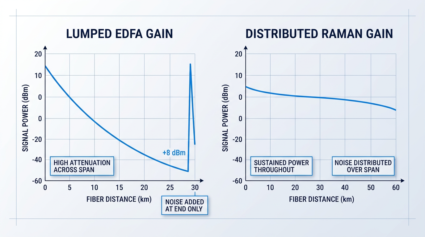
The OSNR advantage of DRA follows directly from this geometry. In a lumped-only EDFA system, the signal attenuates across the full span before being amplified at the end — the amplifier must supply all the gain in one shot, and the noise it adds is proportional to that gain. With distributed Raman, the signal is partially sustained along the span, so the effective gain required at any single point is lower and noise accumulation is reduced.
Measured results confirm the practical magnitude of this benefit: a Raman+EDFA hybrid has been shown to deliver more than 4 dB lower noise floor compared to a conventional EDFA-only arrangement over the same span, directly translating to improved system reach and margin.
Whereas erbium's gain band is fixed by the atomic energy levels of the Er³⁺ ion, Raman's gain band is determined entirely by the pump wavelength. Shifting the pump shifts the gain window — a property that no rare-earth dopant can match.
Pumps in the 1450–1480 nm range produce Raman gain in the S-band (approximately 1460–1530 nm), a spectral region where EDFAs provide little or no amplification. By combining multiple pump wavelengths at different powers, engineers can shape the Raman gain spectrum to produce a wide, flat gain profile across a target band — the functional equivalent of a gain-flattening filter, but achieved by tuning the pump plan rather than inserting a passive optical element.
Engineering Challenges of Raman Amplification
Raman amplification's advantages come with real engineering costs that practitioners must account for in system design.
- High pump power requirement: Raman amplifiers typically require pump powers in excess of 700 mW and often greater than 1 W — substantially more than a typical EDFA pump.
- Instantaneous gain response: Unlike erbium's ~8–10 ms upper-state lifetime, Raman gain responds to pump fluctuations almost instantaneously. Counter-propagating pump geometry is the standard mitigation, averaging out RIN transfer over the span.
- Double-Rayleigh backscatter (DRBS): Signal light scattered twice within the fibre re-enters the signal path as multipath interference noise, setting a fundamental limit on single-stage distributed Raman gain.
These are engineering constraints to be managed, not disqualifying limitations. The systems where Raman amplification is deployed are precisely those where the OSNR improvement justifies the added complexity and pump power cost.
In practice, distributed Raman amplification is deployed as a complement to EDFAs in ultra-long-haul and submarine systems where OSNR budget is the binding constraint. Raman pre-amplification improves span OSNR, while an EDFA provides the bulk gain at the span end — the two technologies are used together rather than as alternatives. One published network analysis found that adding distributed Raman at each inline amplifier site allowed a fully populated DWDM signal to traverse approximately twice the span count before requiring electrical regeneration compared to an EDFA-only design.
In the most demanding long-haul and submarine systems, distributed Raman amplification improves OSNR span by span while EDFAs supply the bulk gain — the two technologies are routinely combined because neither alone is sufficient at extreme reach.
With Raman amplification's role in long-haul systems established, the next amplifier type in the landscape operates on an entirely different physical platform: a semiconductor gain medium driven by electrical injection rather than an optical pump.
Semiconductor Optical Amplifiers (SOAs)
Every amplifier type covered so far — EDFA and Raman — is fundamentally a fibre-based device, optically pumped and built around the physics of glass. The semiconductor optical amplifier breaks from that world entirely: it is a chip-scale device, electrically pumped, and fabricated using the same semiconductor processes as laser diodes and photodetectors.
The operating principle follows directly from what was established in §4: electrical current injection drives electrons into the conduction band of the semiconductor gain medium, creating population inversion across the active region, and an optical signal passing through the waveguide stimulates the emission of coherent photons.
A useful way to picture the SOA is as a semiconductor laser diode with its end facets anti-reflection coated so that light travels through the gain region once rather than oscillating to form a cavity — amplification without resonance.
The physical scale of the gain medium is one of the starkest contrasts with EDFAs: where an EDFA requires metres of doped fibre to build up gain, an SOA achieves amplification across a waveguide just a few hundred micrometres to a few millimetres long, enabling potential integration with other semiconductor components on a single chip.
SOAs offer a relatively broad gain bandwidth and can be engineered to operate at either the 1550 nm or 1310 nm transmission windows — a waveband flexibility that EDFAs, constrained by the erbium gain spectrum, cannot match.
The carrier dynamics in a semiconductor gain medium are also exceptionally fast — far faster than the millisecond-scale dynamics of erbium ions in an EDFA — which has significant consequences for how SOAs behave in multi-channel systems.
Those fast dynamics introduce the SOA's most consequential trade-offs: noise figures are typically higher than those of EDFAs, and saturation output power is lower — both of which matter significantly in long-haul, high-channel-count transmission.
WDM Limitations: Cross-Gain and Cross-Phase Modulation
The root of the SOA's difficulty in dense WDM systems is its comparatively low saturation energy: as total input power rises, the carrier population depletes and gain compresses rapidly across the entire gain bandwidth.
In a multi-channel WDM system, this creates a coupling mechanism between channels: when one channel's power fluctuates, the resulting gain compression is felt across all co-propagating channels simultaneously — a phenomenon known as cross-gain modulation (XGM).
Because the refractive index of the semiconductor gain medium is tied to the carrier density, the same carrier depletion that drives XGM also imposes phase shifts on co-propagating channels — this is cross-phase modulation (XPM) in the SOA context.
Critically, this is not a limitation that better device engineering can eliminate: the fast carrier lifetime that makes XGM and XPM so pronounced is an intrinsic property of the semiconductor material, not a consequence of imperfect fabrication.
Polarisation-dependent gain (PDG) presents a further challenge: because the SOA waveguide has an inherently asymmetric cross-section, the gain experienced by TE-polarised and TM-polarised signals differs. Designing the active region with a near-square cross-section is the standard mitigation strategy, and careful waveguide engineering can bring PDG to practically manageable levels — though it remains a design constraint that requires deliberate attention, unlike EDFAs where PDG is negligibly low by nature.
Where SOAs Excel
The characteristics that limit SOAs in high-channel-count WDM amplification are, in several other contexts, precisely what makes them the right tool for the job.
- Optical switching and gating: Fast carrier dynamics allow SOAs to function as rapid optical gates, switching or routing signals at speeds impractical for fibre-based amplifiers.
- Wavelength conversion: XGM and XPM — liabilities in WDM amplification — become deliberate tools for transferring modulated data from one carrier wavelength to another.
- Metro and access networks: With fewer WDM channels present, interchannel crosstalk is far less severe, making SOAs viable and cost-effective amplification elements.
- Booster and pre-amplifier roles: In short-reach applications, the compact footprint and electrical pumping offset the higher noise figure and lower saturation power.
- Next-generation PON systems: Direct electrical drive, compact size, and photonic integration potential give SOAs genuine engineering advantages in passive optical network architectures.
The common thread across these applications is that electrical pumping — requiring no separate pump laser diode — combined with compact semiconductor integration, suits contexts where system simplicity, physical footprint, and optical switching speed matter more than the noise performance that dominates long-haul system design.
In dense WDM amplification, XGM and XPM are treated as impairments to be minimised. In wavelength conversion systems, the same effects are deliberately exploited as the functional mechanism — the same physical interaction, opposite engineering intent.
The fourth amplifier type in this guide takes yet another approach to optical gain: rather than electronic transitions in ions or semiconductor carriers, optical parametric amplifiers exploit nonlinear photon interactions within the fibre itself — a fundamentally different physical basis with its own distinct set of capabilities and constraints.
Optical Parametric Amplifiers
The three amplifier families covered so far — EDFAs, Raman amplifiers, and SOAs — each rely on a distinct physical mechanism: rare-earth stimulated emission, stimulated Raman scattering, and electron-hole recombination respectively. Optical parametric amplifiers (OPAs) complete the taxonomy with a fourth mechanism entirely: parametric amplification via a nonlinear optical interaction in the fibre itself, requiring no dopant, no semiconductor junction, and no molecular vibration.
The gain mechanism in fibre OPAs is four-wave mixing (FWM), a third-order nonlinear optical process arising from the Kerr nonlinearity of silica glass.
In the degenerate case most relevant to amplification, two photons from a high-power pump wave interact with a signal photon: the result is an amplified signal photon and a new photon at a different frequency, called the idler, generated symmetrically on the other side of the pump wavelength.
Energy is conserved across this interaction — the relationship 2wp = ws + wi must hold — but efficient energy transfer also requires that momentum is conserved, which is where the central engineering challenge of OPAs arises.
FWM is a phase-sensitive process: the interaction only accumulates coherently over a useful fibre length if the phase-matching condition is satisfied, meaning the phase mismatch between pump, signal, and idler waves must be kept close to zero.
Without phase matching, the parametric gain interaction is incoherent — energy transferred to the signal in one segment of fibre is returned to the pump in the next, and net amplification does not build up.
Satisfying the phase-matching condition requires careful management of the fibre's chromatic dispersion; in practice, the pump wavelength is typically positioned near the fibre's zero-dispersion wavelength, where the group-velocity dispersion can be made small enough to allow efficient FWM over useful propagation distances.
OPAs can operate in two distinct regimes depending on what is present at the amplifier input.
In phase-insensitive mode, only the signal enters the amplifier; the idler is generated internally during propagation, and the amplifier can deliver high gain across broad bandwidths.
In phase-sensitive mode, both the signal and the idler are injected at the input with a controlled phase relationship relative to the pump; the two waves add coherently at the output while their uncorrelated noise contributions add only in power — a quantum-mechanical property that enables the amplifier to approach a noise figure of 0 dB.
In phase-sensitive operation, an OPA can theoretically achieve a noise figure of 0 dB — meaning the amplifier adds no noise to the signal. This is below the 3 dB quantum limit that constrains every phase-insensitive amplifier, including EDFAs. No other fibre amplifier class shares this property. In practice, the lowest measured noise figure for a fibre-based phase-sensitive OPA is 1.1 dB at 26 dB gain — still well below the EDFA quantum floor.
Achieving 0 dB noise figure in practice demands that the pump, signal, and idler waves are all frequency- and phase-locked at the amplifier input — a requirement that drives substantial system complexity.
The pump laser must have a very narrow spectral linewidth to maintain the coherence needed for stable phase-sensitive gain; experimental demonstrations have used lasers with linewidths on the order of 100 Hz or below to achieve reliable phase locking.
A further practical constraint is that the idler wave occupies part of the available spectral bandwidth — at the expense of using half of the available bandwidth for propagating the idler — reducing the spectral efficiency of any OPA-based transmission system.
These factors together explain why, despite their theoretically attractive properties, fibre OPAs have not followed EDFAs into widespread commercial deployment; no commercial implementation has yet been developed that meets the full requirements of optical communication systems.
Where OPAs are genuinely relevant today is in research and specialist applications: wavelength conversion (the idler is produced at a new frequency, making it directly useful as a frequency-shifted copy of the signal), all-optical signal processing including phase regeneration, squeezed-state generation for quantum optics, and amplification in wavelength bands not served by EDFAs or Raman amplifiers, where the pump wavelength and fibre dispersion can be engineered to reach otherwise inaccessible spectral regions.
With all four amplifier families now mapped — EDFA, Raman, SOA, and OPA — the guide shifts from component-level mechanisms to the cross-cutting performance parameters that matter when specifying or comparing them: noise figure, gain flatness, gain saturation, polarisation-dependent gain, and amplification bandwidth.
Key Performance Parameters
Knowing how each amplifier type works is only half the engineering problem. The other half is understanding the parameters that determine whether a chosen amplifier will actually perform in a real link — and what happens when one of those parameters is misspecified. Noise figure, gain saturation, gain flatness, polarisation-dependent gain, and amplification bandwidth are not datasheet footnotes; they are the axes on which optical links succeed or fail at scale.
Noise Figure
Every amplifier degrades the signal-to-noise ratio of the light passing through it — the question is by how much. Noise figure (NF) quantifies that degradation: it is the ratio of input SNR to output SNR, expressed in decibels, and it captures the fundamental cost of amplification.
For any phase-insensitive amplifier, 3 dB is the theoretical quantum limit — an unavoidable floor set by the physics of stimulated emission and the accompanying amplified spontaneous emission (ASE). Standard EDFAs and Raman amplifiers operating in conventional mode cannot beat it. Well-designed EDFAs in practice achieve noise figures of 4–6 dB, with the gap above the 3 dB floor reflecting real-world imperfections in inversion, pump efficiency, and passive component losses.
Where an amplifier sits in the link matters as much as its NF value. In a preamplifier — placed immediately before a receiver where the signal is at its weakest — every tenth of a dB of noise figure directly erodes the receiver's sensitivity margin. In a booster amplifier placed right after the transmitter, the signal power is high and the noise added represents a much smaller fractional penalty.
In a multi-span link, noise accumulates at every amplifier stage and the total system noise figure is dominated by the first amplifier in the chain — a consequence of the same cascade logic that governs all amplifier chains. This is why the NF specification of the first inline amplifier in a long-haul system carries disproportionate weight: a mediocre first stage cannot be rescued by excellent amplifiers downstream.
Gain Saturation
Gain saturation occurs when the input signal power approaches the amplifier's saturation power, causing the gain to compress — the amplifier can no longer deliver proportionally more output power regardless of how much more input is applied. In an EDFA, the mechanism is the depletion of the excited erbium ion population inversion: as more signal photons arrive, more ions are stimulated per unit time, drawing down the inversion faster than the pump can replenish it.
The most immediate engineering consequence is an output power ceiling. In a WDM system carrying many channels, the amplifier operates against the aggregate power of all channels simultaneously — specifying against per-channel power alone will produce an undersized amplifier that saturates well below the intended operating point.
A subtler but equally serious consequence arises during channel add/drop events. When channels are added or removed during network reconfiguration, the surviving channels suddenly see a different total input power. Because the amplifier operates near saturation, this triggers a transient gain excursion — the remaining channels receive a burst of excess or insufficient gain that, without fast gain control, can cause bit errors or receiver overload.
Saturation also has a beneficial side-effect in cascaded chains: an amplifier receiving slightly too much power compresses its gain and reduces output, while one receiving slightly too little operates at higher gain and compensates. This self-regulating behaviour can be deliberately exploited in long-haul system design to stabilise channel powers across many spans without active intervention at every node.
Gain Flatness
The gain spectrum of an EDFA is not uniform across the C-band. There is a pronounced peak near 1530–1532 nm, with gain falling toward longer wavelengths. In a WDM system, this means channels at different wavelengths receive different amounts of amplification — an inequality that is manageable at a single stage but becomes a serious problem in cascaded systems.
A gain non-uniformity of even 1 dB per amplifier stage compounds dramatically across a long link. After 20 or 50 cascaded stages — typical of terrestrial long-haul or submarine systems — the accumulated gain tilt can reach tens of dB of channel power variation. The strongest channels saturate receivers; the weakest fall below the noise floor. The link fails not because of average OSNR but because of the spread across channels.
Gain-flattening filters (GFFs) are the primary mitigation: passive optical filters with a complementary loss profile are inserted within or between amplifier stages to offset the gain peak near 1532 nm. Careful optimisation of erbium fibre length and pump power also shapes the gain spectrum. In systems where gain tilt evolves over time due to ageing or temperature variation, dynamic gain equalisation provides active correction that a static GFF cannot.
Gain flatness is primarily an EDFA concern because the gain spectrum is fixed by the erbium ion's energy structure. Raman amplifiers, whose gain band is shaped by pump wavelength rather than a dopant's energy levels, can be configured with multiple pumps to achieve a substantially flatter profile — one reason hybrid Raman-EDFA designs are used in systems where flatness across a wide band is critical.
Polarisation-Dependent Gain
Polarisation-dependent gain (PDG) is the difference in gain experienced by orthogonally polarised components of the signal. An amplifier with significant PDG amplifies one polarisation state more than the other — a problem in real fibre links where the signal's polarisation state varies continuously due to birefringence and environmental perturbations.
EDFAs have a structural advantage here: erbium ions in a silica glass matrix are randomly oriented, making the gain medium essentially isotropic. The PDG of a well-made EDFA is very low, making polarisation a non-issue for the vast majority of EDFA-based deployments.
SOAs present a more challenging picture. The rectangular waveguide geometry of a standard SOA creates an anisotropic gain medium where the TE and TM polarisation modes see different modal overlap with the active region. Strain engineering of the active layer — using tensile-strained quantum wells to balance TE and TM gain — can substantially reduce PDG, with optimised structures achieving TE/TM gain imbalances below 1 dB. However, it remains a genuine design constraint that passive waveguide adjustment alone cannot fully resolve.
The scalability consequence of PDG in cascaded SOA chains is severe. Research by Roudas and Antoniades demonstrated that even commercially available SOAs with PDG in the 0.5–1.5 dB range create significant OSNR variation when concatenated in series — and that this variation grows with the number of stages, setting a hard upper limit on how many SOAs can be cascaded before outage probability becomes unacceptable. For a 1 dB OSNR margin allocated to PDG, as few as four SOAs in series may exhaust the budget at 0.5 dB PDG per stage.
Distributed Raman amplifiers also exhibit some PDG because the Raman gain coefficient is polarisation-selective. The standard mitigations — counter-propagating pumps and depolarised pump sources — are well established in commercial systems and reduce Raman PDG to a manageable level in most configurations.
Amplification Bandwidth
Amplification bandwidth is one of the first filters in technology selection: it determines how many WDM channels an amplifier can serve simultaneously and whether it can cover the transmission bands a given system requires. A mismatch between amplifier bandwidth and system channel plan is not a performance trade-off — it is a disqualifying constraint.
| Technology | Gain Band(s) | Approximate Bandwidth | Key Flexibility Note |
|---|---|---|---|
| EDFA (C-band) | 1530–1565 nm | ~35 nm | Densest DWDM deployment band; gain peaks near 1532 nm |
| EDFA (L-band) | 1565–1625 nm | ~60 nm | Requires different erbium fibre length and pump configuration |
| Raman amplifier | S-, C-, L-, O-band (pump-dependent) | Flexible; multi-pump designs can span 90+ nm continuously | Gain band set by pump wavelength — not fixed by dopant energy levels |
| SOA | 1310 nm or 1550 nm window (material-dependent) | ~30–100 nm per device | Can cover 1310 nm band; broad gain but with cross-gain modulation trade-offs |
| OPA | Determined by phase-matching conditions | Potentially very wide (hundreds of nm in principle) | Practical bandwidth constrained by phase-matching in any given configuration |
Comparison of amplification bandwidth across the four main fiber optic amplifier technologies, with specific wavelength ranges and bands sourced from research material.
The table reveals an important pattern: raw bandwidth and system suitability are not the same thing. An SOA covering 100 nm looks attractive on paper, but its higher noise figure means OSNR degrades rapidly with distance, limiting it to shorter metro links. Raman's pump-wavelength flexibility makes it the technology of choice for wideband and multi-band research, but it requires careful pump management to maintain a flat gain profile across that bandwidth. The EDFA's 35 nm C-band coverage is narrower than either, yet it remains the workhorse of long-haul DWDM precisely because its noise figure and gain characteristics are optimised for that band.
Bandwidth interacts with every other parameter discussed in this section. A wider gain band with poor noise figure may deliver worse system performance than a narrower amplifier with excellent NF. Gain flatness across a wide band is harder to achieve and more sensitive to operating point drift. The right bandwidth specification is always a system-level decision, not a component-level preference.
OSNR: The System-Level Metric
Optical signal-to-noise ratio (OSNR) is the single metric that unifies all five parameters above at the system level. Noise figure determines how much ASE each amplifier contributes; output power determines the signal level leaving each stage; span loss determines how far the signal degrades between amplifiers; and the number of spans determines how many times noise accumulates. All of these feed directly into the OSNR at the receiver.
The engineer's goal is to maintain adequate OSNR across the full link — from transmitter to receiver — for every channel simultaneously. In a DWDM system, gain flatness failures express themselves as per-channel OSNR variation; PDG in cascaded SOA chains appears as OSNR fluctuation correlated with polarisation state; gain saturation from channel transients shows up as sudden OSNR excursions. Every parameter discussed in this section ultimately registers as an OSNR event.
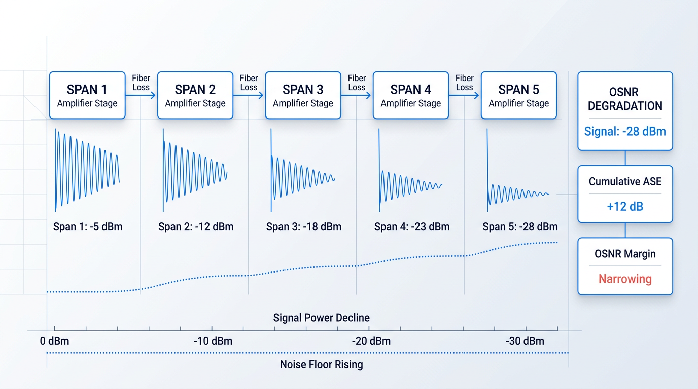
The critical insight is that OSNR cannot be optimised by tuning any single parameter in isolation. Reducing noise figure helps, but if span loss is high the benefit is limited. Increasing output power improves OSNR margin but risks nonlinear distortion. Reducing amplifier spacing improves OSNR but adds infrastructure cost. These are genuinely coupled trade-offs, and chasing any one of them without accounting for the others is how well-intentioned amplifier specifications produce poorly performing links.
Every amplifier parameter — noise figure, gain flatness, gain saturation, polarisation-dependent gain — ultimately expresses itself as an OSNR event at the receiver. A component that looks excellent in isolation can still produce a failing link if the system-level trade-offs are not accounted for.
With these parameters established as a framework, the question becomes how they interact in the specific engineering contexts where fiber optic amplifiers are actually deployed — and that is where the trade-offs become concrete rather than abstract.
See EDFA Specifications That Match Your Requirements
You now know which parameters matter most in amplifier selection. Download a datasheet to put those parameters in context against a real device — noise figure, gain, and output power included.

Deployment Contexts and System-Level Considerations
The same EDFA technology that sits inside a submarine repeater on a transoceanic cable and the one that extends a rural GPON link to 60 km are, in hardware terms, closely related devices — but they are solving entirely different engineering problems, operating under entirely different constraints, and failing for entirely different reasons when misspecified. Understanding which deployment context you are designing for is not background knowledge; it is the foundation of every amplifier decision that follows.
Terrestrial Long-Haul Networks
In terrestrial long-haul networks, EDFAs are placed as inline amplifiers at intervals that balance fibre attenuation against OSNR accumulation — typically every 70–80 km, though the ITU-T Optical Fibre Transmission Handbook notes that practical amplifier spacing is also constrained by route geography and the locations of equipment huts, placing it anywhere from 45 to 100 km in real deployments.
Each amplifier stage adds amplified spontaneous emission (ASE) noise, so OSNR degrades progressively along the chain — and the maximum unregenerative reach is not set by any single parameter in isolation, but by the interplay of span loss, amplifier output power, and noise figure together. Reducing span loss by shortening amplifier spacing, increasing output power, or improving noise figure each buys reach; the engineering task is finding the right balance given the fixed constraints of the route.
Submarine and Ultra-Long-Haul Systems
Submarine and transoceanic systems push the cascaded-amplifier problem to its extreme: span spacing tightens to approximately 50 km, and total link distances of 6,000–8,000 km mean a signal may traverse many dozens of amplifier stages without a single regeneration point, as confirmed by the ITU-T Handbook's analysis of repeater spacing versus propagation distance for transoceanic links.
The standard approach for improving OSNR per span in these systems is the combination of lumped EDFAs with distributed Raman amplification — a pairing that works because Raman gain is spread continuously along the transmission fibre, preventing the signal from dropping as low before the EDFA sees it, which effectively reduces the noise contribution of each span and extends total reach.
Submarine amplifiers also face reliability demands that have no equivalent in terrestrial engineering: ITU-T G.977 specifies a 25-year design lifetime as standard, with fewer than three cable-ship interventions permitted over that period. Every amplifier in the chain is powered remotely via the cable's electrical conductor from shore-based power feed equipment, and because field repair of a submerged repeater is prohibitively expensive, the engineering consequence is that component reliability — not peak performance — drives the design.
Metro and Regional Networks
Metro and regional rings present a different challenge: span lengths are shorter on average, but they vary considerably across the same ring — a mix of short spans under 20 km, medium spans of 20–80 km, and occasional extended spans above 80 km can all appear within a single DWDM ring, as documented in Lightwave Online's analysis of multihaul DWDM network design.
The standard solution for managing both dispersion and noise across this diversity is the dual-stage EDFA with mid-stage access: a low-noise first stage compensates the preceding span loss, a dispersion compensation module (DCM) occupies the mid-stage slot, and a high-power second stage relaunches the signal — all within a single amplifier unit, avoiding the noise penalty that a separate amplification stage would introduce.
Shorter spans on the same ring may use single-stage EDFAs, while extended spans may add a Raman booster to the EDFA configuration. This means a single metro ring can simultaneously deploy multiple amplifier configurations — a real engineering complexity that practitioners encounter during network design and that makes gain flatness and transient suppression particularly important EDFA parameters in this context.
FTTH and Access Networks
In passive optical network (PON) architectures for FTTH, EDFAs serve a fundamentally different role: they are reach extenders, not span compensators. ITU-T G.984.6 defines the architecture for GPON reach extension using optical amplifiers or regenerators in the fibre link between the OLT and ONT, specifying a maximum physical reach of 60 km with loss budgets exceeding 27.5 dB in both spans — extending the standard 20 km GPON reach threefold.
The engineering problem here is not ASE accumulation across many spans — there is only one amplification stage — but the split-loss power budget: optical power is divided among many subscribers through passive splitters, and the amplifier must overcome that division loss while extending reach to underserved or rural areas that the standard link budget cannot serve. ITU-T G.987.4 extends the same reach extension framework to XG-PON systems, with loss budgets exceeding 28.5 dB.
A related deployment consideration in FTTH and other contexts involving human exposure is the eye-safety advantage of the 1550 nm transmission window. Wavelengths beyond 1400 nm are absorbed in the anterior portions of the eye — primarily the cornea — and cannot reach the retina, which is the primary site of laser-induced injury at shorter wavelengths such as 1064 nm. This physical difference is reflected in laser safety standards: 1550 nm sources can be operated at significantly higher power levels within Class 1 or Class 1M classifications, which affects hazard zone sizing, safety classifications, and field installation procedures in contexts where technicians may be exposed to live fibre.
The table below summarises the four deployment contexts across the key engineering axes — span length, amplifier configuration, and primary engineering challenge — to make the differences concrete before drawing out the system-level thread that connects them all.
| Deployment Context | Typical Span Length | Amplifier Configuration | Primary Engineering Challenge | Key Reference |
|---|---|---|---|---|
| Terrestrial Long-Haul | 45–100 km (typically 70–80 km) | Inline EDFA; hybrid EDFA + Raman for extended reach | Joint optimisation of span loss, output power, and NF to maximise unregenerative reach | ITU-T Optical Fibre Transmission Handbook |
| Submarine / Ultra-Long-Haul | ~50 km; total link 6,000–8,000 km | EDFA + distributed Raman amplification per span | OSNR accumulation across dozens of stages; 25-year reliability; remote powering via cable conductor | ITU-T G.977; ITU-T G.Suppl.41 |
| Metro / Regional | Mixed: <20 km to >80 km on same ring | Single-stage EDFA (short spans); dual-stage EDFA with mid-stage access for DCM (medium/long spans); Raman booster for extended spans | Dispersion compensation without noise budget penalty; managing varied span lengths on one ring | Lightwave Online multihaul DWDM analysis |
| FTTH / PON Access | Up to 60 km (extended from 20 km baseline) | Single EDFA as mid-span reach extender | Split-loss power budget: overcoming passive splitter losses to serve rural or underserved subscribers | ITU-T G.984.6; ITU-T G.987.4 |
Side-by-side comparison of four fiber optic amplifier deployment contexts by span length, amplifier configuration, primary engineering challenge, and key standard or reference.
What the table makes clear is that span length and amplifier configuration are not the only axes of difference — the nature of the engineering problem shifts completely between contexts. Submarine systems demand that every component survive 25 years without intervention; metro rings demand that a single amplifier unit handle wildly different span conditions on the same ring; FTTH demands that a single amplifier stage overcome split losses rather than manage a noise cascade. Selecting an amplifier optimised for one context and deploying it in another is a reliable path to a system that underperforms in ways that are difficult to diagnose.
The thread connecting all four contexts is the behaviour of ASE noise in cascaded systems — and it is worth making that explicit before moving to specification.
In a chain of N amplifiers, total ASE noise scales with N — OSNR degrades with every stage added. This means noise figure, amplifier output power, and span loss are not independent design parameters: improving one while ignoring the others produces diminishing returns. The system-level OSNR constraint ties them together, and any amplifier specification that treats them in isolation will produce a link that falls short of its reach target.
Knowing which deployment context you are designing for — and which engineering problem you are actually solving — is the essential precondition for writing a meaningful amplifier specification. That translation from context to specification is the subject of the next section.
Specifying and Sourcing a Fiber Optic Amplifier
Understanding the physics and the technology families is the necessary foundation — but the moment a specification document opens, the engineering decisions become concrete and consequential in a different way.
Several parameters must be actively decided before any supplier conversation begins; none of them are safe to leave as defaults, because each one shifts the amplifier design rather than simply adjusting a setting.
- Operating band: C-band, L-band, or dual C+L — not interchangeable choices; each shifts the gain medium design and erbium doping profile.
- Output power and gain: Determines whether a single-stage or multi-stage MOPA architecture is required; undersizing here is a common integration problem.
- Noise figure target: Interacts directly with amplifier role — pre-amplifier, inline, or booster — and must be set before the design is finalised.
- Pulse regime: CW versus pulsed operation is a design-level choice; non-standard pulse widths or repetition rates are not a dial to turn post-build.
- Cooling requirement: Air or water cooling is driven by average power dissipation and the integration envelope — not a preference to decide later.
- Form factor: Rack-mount, OEM module, or custom chassis — the mechanical envelope constrains thermal management and connector layout.
- Control interface and firmware: Communication standards and firmware behaviour must match the host system; mismatches here are expensive to fix post-delivery.
These parameters interact: a high average power requirement combined with a non-standard pulse regime will push the design toward water cooling and a multi-stage architecture simultaneously, and the noise figure target will constrain which stage ordering is viable.
The practical consequence is that leaving any one of these as a placeholder — intending to confirm it later — is how integration problems begin, because the supplier will have made design choices to fill the gap.
Catalogue vs. Application-Specific Designs
The optical amplifier market spans a wide range from fixed-configuration catalogue parts to fully application-specific designs, and the right position on that spectrum depends entirely on what the application demands.
Catalogue amplifiers — fixed band, fixed power class, standard form factor — are a rational choice for well-characterised telecom applications where the parameters are standard and availability matters more than fit.
Demanding applications fall outside that envelope: high average power, non-standard pulse regimes, unusual form factors, extreme environments, or use cases beyond standard telecom all benefit from an amplifier engineered around the specific requirements from the outset.
The engineering trade-off is real but straightforward: catalogue selection offers speed and predictability; application-specific design trades some lead time for a result that fits the application rather than approximating it.
Manufacturer vs. Reseller: A Supply Chain Reality
The optical amplifier supply chain includes both manufacturers who design and build in-house and resellers who source amplifiers from OEM manufacturers and sell them under their own brand — a distinction that experienced practitioners already know and that matters considerably in demanding applications.
For standard telecom applications with well-defined parameters, the distinction may carry little practical weight: the catalogue part performs as specified, and post-sale support needs are limited.
For demanding applications, the difference is significant: a reseller cannot modify a design they did not create, cannot provide direct engineering support because their support chain runs back to the OEM, and when something needs to change, the lead time and communication overhead are substantially greater.
A manufacturer, by contrast, can iterate on the design post-delivery, answer integration questions from the engineers who built the component, and make modifications without routing the request through a third party.
Five questions quickly reveal which kind of supplier you are talking to — and whether they can genuinely support a demanding application: Did you design and build this amplifier in-house, or is it sourced from an OEM? Can you modify the design for my specific band, power level, or pulse regime? Who provides engineering support during integration — your own engineers, or a third party? What is the realistic lead time for a custom configuration? Is your technology proprietary, or a standard platform?
When a demanding application needs a design change mid-integration, a reseller's answer is bounded by what their OEM supplier will do and how fast they will respond. A manufacturer's answer is bounded only by their own engineering capacity — a structurally different position.
Woodrow Scientific Limited's Custom EDFA is a concrete example of what the manufacturer-direct model looks like in practice — and it is worth revisiting here, since the sourcing model is as important as the technology.
The platform is tailored end-to-end across operating band (C-band, L-band, or dual C+L), output power, pulse regime (CW, short-pulse, or custom), pulse energy and peak power, cooling (air or water), delivery cable length and termination, form factor and integration envelope, and control firmware and communication standards — configurable up to the highest power levels commercially available for erbium fibre.
Woodrow Scientific Limited (WSL) designs, builds, qualifies, and supports its amplifiers entirely in-house, on patented technology, from its facility in Southampton, UK — the city where the EDFA was invented, at the Optoelectronics Research Centre (ORC).
Founded in 2012 and supplying customers worldwide, WSL brings over 200 years of combined engineering experience to each project; the engineers who answer integration questions are the same engineers who designed and built the amplifier.
On the power side, WSL pushes erbium-fibre output to the leading commercially available levels: pulse energies above 10 mJ, peak powers above 100 kW, and average powers above 100 W — a performance class that requires the kind of application-specific engineering that catalogue parts cannot deliver.
The platform is CE and UKCA certified, available with air or water cooling, capable of delivering both C-band and L-band through a single cable from one source, and operates at the eye-safe 1550 nm wavelength, with reduced-hazard-zone builds available for applications where laser safety margins are a design constraint.
The engineering judgements this guide has built toward — technology selection, performance parameter trade-offs, deployment context, and now sourcing model — come together at the specification stage, and the conclusion draws those threads into a final synthesis.
Conclusion
Conclusion
EDFA dominance is not a market convention that could have gone another way — it is the direct consequence of erbium's gain band sitting precisely where silica fibre loses least light.
That does not make the other amplifier types redundant; it makes them specialists, each earning their place through physics that EDFAs cannot replicate.
What ties all of it together is the system: no performance parameter — noise figure, gain flatness, saturation — carries meaning until it is read against span loss, cascade length, and what sits at the far end.
Frequently Asked Questions
These questions cover the topics readers most commonly ask after working through this guide on fibre optic amplifiers.
There are four main families. EDFAs (erbium-doped fibre amplifiers) are the dominant type in long-haul and DWDM systems, providing gain across the C- and L-bands by exploiting stimulated emission from Er³⁺ ions. Raman amplifiers use stimulated Raman scattering to generate distributed gain along the transmission fibre itself, with no discrete gain element required. SOAs (semiconductor optical amplifiers) are electrically pumped, chip-scale devices suited to switching, metro, and access applications. OPAs (optical parametric amplifiers) exploit four-wave mixing for gain across flexible wavelength ranges, and are used mainly in research and specialist signal processing. The body sections of this guide cover each type in detail.
Noise figure (NF) is the ratio of input signal-to-noise ratio (SNR) to output SNR, expressed in dB. The theoretical minimum for a phase-insensitive amplifier is 3 dB — a floor set by quantum mechanics. Practical EDFAs typically achieve 4–6 dB. NF matters because in a cascaded chain of amplifiers, each stage adds noise proportional to its NF and gain. After many spans, this accumulated noise determines whether the optical signal-to-noise ratio (OSNR) remains above the receiver threshold. Even a 1 dB improvement in NF can meaningfully extend unregenerative reach. NF is most critical for preamplifiers, where the input signal is at its weakest, and less so for booster amplifiers, where the signal enters at its strongest.
Yes — and this is one of the defining advantages of EDFAs. A single EDFA amplifies all WDM (wavelength division multiplexed) channels that fall within its gain window simultaneously, entirely in the optical domain, with no electronics involved. The amplifier count does not scale with channel count, which is the economic and engineering reason EDFAs made high-capacity DWDM networks commercially viable. By contrast, earlier OEO (optical-electrical-optical) repeaters handled one channel per unit. One practical consideration: the Er³⁺ gain spectrum is not perfectly flat, so gain-flattening filters are used in WDM systems to equalise power across channels and prevent stronger channels from accumulating disproportionate gain.
In a lumped (or discrete) amplifier, gain is concentrated in a single component — an EDFA or SOA — placed at a specific point in the link. In a distributed amplifier, gain is spread continuously along the transmission fibre itself. Raman amplification works this way: a pump laser launched into the span causes gain to occur gradually over many kilometres of ordinary fibre, with no separate gain element required. The practical consequence is significant. Distributed gain means the signal never falls as low as it would in a lumped-only system before being amplified, reducing effective noise accumulation and improving OSNR. This is why distributed Raman amplification is a standard tool in ultra-long-haul and submarine links, often used alongside EDFAs for combined benefit.
No — fibre optic communications infrastructure is not becoming obsolete. It is expanding. Long-haul and submarine fibre capacity continues to grow, driven by data centre interconnect, cloud computing, and rising global internet traffic. EDFAs remain the enabling technology for this growth, amplifying signals across transoceanic distances that no wireless technology can replicate. The question likely reflects confusion between specific consumer-facing access technologies and the broader fibre infrastructure underpinning global communications. Those are different layers of the network. The physical fibre and the optical amplifiers that keep signals alive across it are as central to modern communications as they have ever been.