

Introduction
Physics textbooks explain what erbium-doped fiber is; datasheets tell you what a specific product measures. Neither tells you how to make the design decisions that actually determine whether your amplifier performs.
This guide is written for photonics engineers building or specifying EDFAs, researchers working with rare-earth-doped waveguides, and technical procurement specialists evaluating fiber variants for particular deployment environments.
It moves from the material foundations of EDF and how erbium ions produce gain, through the parameters that govern amplifier performance, and into the variant types and application contexts where those parameters become decisive.
The perspective throughout is an engineering one: grounded in real specification decisions, not just the underlying physics.
TL;DR
EDF selection is a co-optimisation problem. Doping level, fiber length, pump wavelength, and integration compatibility are coupled variables — changing one shifts the others. Treating them as independent catalogue choices leads to amplifiers that underperform on paper-perfect specs.
Lot-specific characterisation data, not generic datasheet values, is the non-negotiable baseline for precision amplifier design.
This article covers:

How erbium ions produce gain in the fiber
Pump wavelength selection and performance trade-offs
Dopant concentration, clustering, and fiber length interaction
ASE origins and design consequences
EDF characterisation, splice compatibility, and lot data
EDF variants and application contexts
What Are Erbium-Doped Fibers?
At the heart of every modern long-haul optical network is a deceptively simple material: a length of glass fiber whose core contains a trace quantity of a rare-earth element. Erbium-doped fiber (EDF) is a specialty optical fiber in which trivalent erbium ions (Er³⁺) are incorporated into the silica glass core, giving the fiber characteristic absorption and emission properties across the 1530–1610 nm wavelength band — precisely the spectral region that matters most for optical communications.
Why Silica Is the Dominant Host Glass
Although researchers have investigated many host glasses for erbium amplification, virtually all commercially available EDF is based on high-silica fiber.
Silica's dominance comes down to three practical realities: its optical transparency across the relevant wavelength band, its mechanical robustness under fiber-drawing and deployment conditions, and — most critically — its direct compatibility with the global installed base of standard telecom fiber.
That compatibility means EDF can be spliced into transmission systems without exotic handling, and that the material science of silica-based EDF is the engineering-relevant one for amplifier design.
Electronic Structure of Er³⁺ in Glass
In a glass matrix, erbium forms trivalent ions with the electronic configuration [Xe]4f¹¹5s²5p⁶ — a partially filled 4f shell shielded from the surrounding host by the outer 5s and 5p electron layers.
This shielding is consequential: it makes the 4f–4f optical transitions relatively insensitive to the precise composition of the host glass, which is why EDF from different manufacturers — with different co-dopant formulations — still produces broadly similar emission wavelengths.
The 1530–1610 nm emission is therefore a reliable property of Er³⁺ in silica, not a compositional accident, and engineers can treat it as a stable material characteristic when designing amplifier systems.
The Key Radiative Transition and Its Significance
The gain in EDF originates from a single principal transition: the radiative decay of Er³⁺ from the ⁴I₁₃/₂ metastable excited state to the ⁴I₁₅/₂ ground state manifold, producing emission centred around 1530–1535 nm and extending through the C-band (approximately 1530–1565 nm) into the L-band (1565–1610 nm).
The strategic importance of this wavelength cannot be overstated: it coincides with the minimum-loss transmission window of standard silica fiber, where attenuation reaches approximately 0.2 dB/km — a physical minimum set by the interplay of Rayleigh scattering and infrared absorption in the Si–O glass network.
The ⁴I₁₃/₂ → ⁴I₁₅/₂ transition of Er³⁺ emits at exactly the wavelength where silica fiber loses the least light. This coincidence — material property meeting infrastructure reality — is the reason erbium-doped fiber became the enabling technology for long-haul optical communications.
This alignment between the Er³⁺ emission band and the ultra-low-loss window of silica fiber drove the development of the EDFA in the late 1980s and made it possible to transmit and amplify optical signals over thousands of kilometres without optical-to-electrical conversion.
The Metastable State Lifetime and Population Inversion
What makes EDF practical as a gain medium is not just where it emits, but how long excited ions remain available to emit — and here the ⁴I₁₃/₂ level has an exceptional property.
The fluorescence lifetime of the ⁴I₁₃/₂ metastable state in silica-based EDF is on the order of 10 ms under conditions of no ion-ion interaction — orders of magnitude longer than the pump excited states above it.
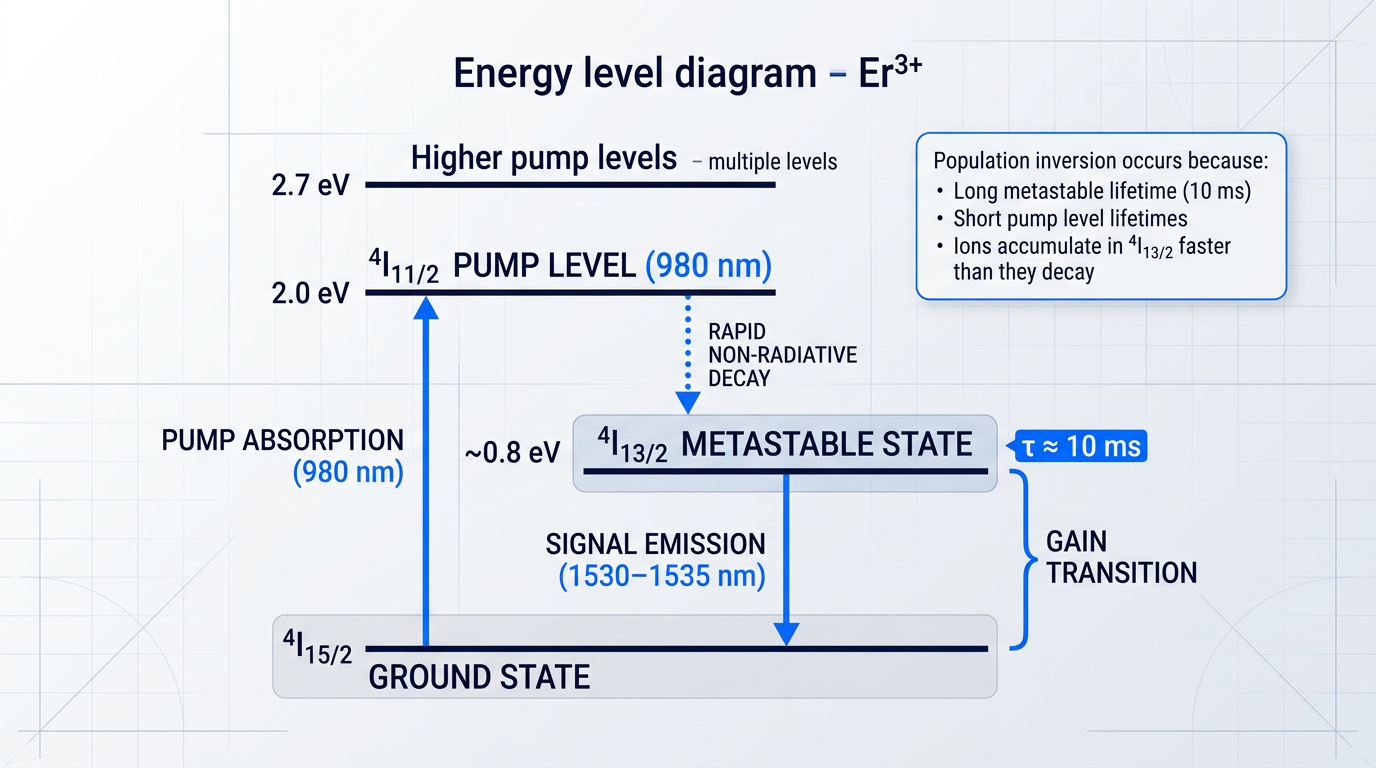
Because pump levels above the ⁴I₁₃/₂ state have very short lifetimes, absorbed pump energy is rapidly funnelled non-radiatively into the metastable level rather than being lost to spontaneous emission at the pump wavelength.
The result is a long-lived reservoir of excited Er³⁺ ions: under continuous pumping, ions accumulate in the ⁴I₁₃/₂ state faster than they decay spontaneously, establishing the population inversion that makes stimulated emission — and therefore optical gain — possible.
Stark Splitting and the Broad Gain Spectrum
EDF does not amplify a single wavelength — it amplifies a band spanning tens of nanometres, and the physical reason is Stark splitting.
The local electric field of the silica glass matrix splits the ⁴I₁₃/₂ and ⁴I₁₅/₂ energy manifolds into a range of sub-levels; because silica is amorphous rather than crystalline, the local field varies from site to site across the glass, producing inhomogeneous broadening of the overall gain spectrum.
The gain bandwidth of EDF extends from approximately 1525–1565 nm in the C-band, primarily as a result of this Stark splitting of the high-angular-momentum ground and first excited states of Er³⁺ in the glass matrix's local electric fields.
The practical consequence is that a single EDF can simultaneously amplify many wavelength-division multiplexed (WDM) channels across the C-band — a capability that is foundational to modern DWDM transmission and is taken as given in the amplifier design discussions that follow.
Fabricating EDF: Incorporating Er³⁺ into the Core
Erbium ions cannot simply be mixed into silica — their incorporation requires specific manufacturing steps that determine the doping level and spatial distribution of Er³⁺ in the fiber core.
The two dominant deposition platforms for commercial EDF production are MCVD (Modified Chemical Vapour Deposition), in which glass layers are deposited inside a rotating silica substrate tube, and OVD (Outside Vapour Deposition), in which soot is deposited on an external mandrel.
Rare-earth incorporation by vapour phase alone is impractical because Er precursors have very low vapour pressure at accessible temperatures, so the dominant method is solution doping: a porous, unsintered core soot layer is deposited at reduced temperature, then soaked in a rare-earth chloride solution (typically an alcoholic or aqueous ErCl₃ solution), drained, dried, and dehydrated before being sintered into a dense glassy layer and the tube collapsed into a solid preform for fiber drawing.
The doping level and radial distribution of Er³⁺ in the core are set at this solution-soaking step — they are manufacturing variables controlled by solution concentration, soot porosity, and soak duration, not fixed material constants.
Co-Dopants: Aluminium, Phosphorus, and Germanium
Er³⁺ has very low solubility in pure silica glass: even at modest concentrations, ions cluster together, and clustered ions lose their gain contribution through ion-ion energy transfer rather than stimulated emission — a phenomenon known as concentration quenching.
Co-dopants are therefore essential in commercial EDF, and their selection directly shapes the fiber's gain spectrum and radiation sensitivity.
- Aluminium oxide (Al₂O₃): The dominant co-dopant. Acts as a network modifier that increases Er³⁺ solubility, suppresses clustering, and broadens and smooths the gain spectrum across the C-band.
- Phosphorus pentoxide (P₂O₅): Also increases Er³⁺ solubility and can produce larger emission cross-sections, but yields narrower gain spectra and carries different radiation sensitivity characteristics than aluminium.
- Germanium dioxide (GeO₂): Added to raise core refractive index for waveguiding. Not an erbium solubility enhancer; aluminium co-doping permits higher Er concentrations before quenching than germanium alone.
The standard commercial EDF core glass architecture that results from these requirements is the ternary Al-Ge-Si oxide system: an aluminogermanosilicate core with a pure silica cladding, as confirmed by first-party manufacturer documentation.
Most commercial EDFAs today use aluminium co-doped fibers precisely because they offer broader and smoother gain spectra than phosphorus-doped alternatives — a design preference that traces directly back to the co-dopant physics established here.
EDF is the gain medium at the core of an EDFA (erbium-doped fiber amplifier), but this guide focuses on the fiber itself — its material properties, fabrication, and how those properties govern performance — rather than the surrounding amplifier architecture of pump lasers, isolators, and WDM couplers.
With this material foundation in place, the next critical question is how pump energy is delivered to establish population inversion in the ⁴I₁₃/₂ state — and specifically how the choice of pump wavelength governs the efficiency and noise performance of that process.
Pump Wavelength Requirements: 980 nm vs. 1480 nm
Both 980 nm and 1480 nm pump wavelengths produce gain in erbium-doped fibre — yet they produce fundamentally different amplifiers. The difference traces directly to which energy levels each pump wavelength engages, and that distinction cascades through every performance metric that matters to an amplifier designer: noise figure, power conversion efficiency, thermal load, and pump laser cost.
980 nm Pumping: The Three-Level Pathway
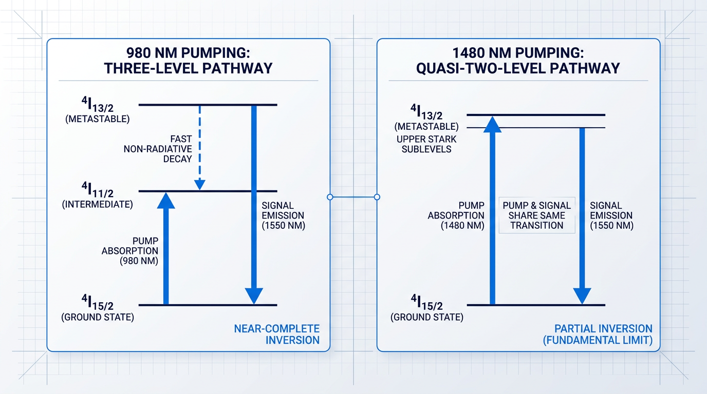
At 980 nm, pump photons excite Er³⁺ ions from the ground state (⁴I₁₅/₂) up to the ⁴I₁₁/₂ level — a transition that sits well above the metastable ⁴I₁₃/₂ manifold where signal amplification occurs.
From ⁴I₁₁/₂, ions decay non-radiatively to the ⁴I₁₃/₂ metastable level on a timescale far shorter than the radiative lifetime of the ⁴I₁₃/₂ state — the intermediate level empties almost as soon as it fills.
This rapid intermediate decay is the critical feature: because the ⁴I₁₁/₂ → ⁴I₁₃/₂ step is non-radiative, stimulated emission cannot compete with the pump absorption step. The pump photon is absorbed into a transition that the signal field never touches, so the two processes are effectively decoupled.
The practical consequence is near-complete population inversion — the vast majority of Er³⁺ ions can be driven into the upper ⁴I₁₃/₂ level, with very few remaining in the ground state to absorb signal photons.
1480 nm Pumping: The Quasi-Two-Level Pathway
At 1480 nm, pump photons excite ions directly from ⁴I₁₅/₂ into the upper Stark sublevels of the ⁴I₁₃/₂ manifold — the same manifold from which signal amplification occurs.
Because both pump and signal transitions share the ⁴I₁₃/₂ ↔ ⁴I₁₅/₂ pair of levels, the pump photon can itself stimulate emission: it competes against the very inversion it is trying to build. This is the defining characteristic of the quasi-two-level excitation scheme.
The result is that complete population inversion is physically unachievable with 1480 nm pumping — a fundamental constraint imposed by the shared transition, not an engineering limitation that higher pump power can overcome.
Noise Figure: The Most Consequential Difference
The inversion quality gap between the two pathways translates directly into noise figure — the metric that most constrains system architecture in long-haul DWDM links.
Because 980 nm pumping achieves near-complete inversion, it can approach the quantum noise limit for optical amplification, enabling significantly lower minimum noise figures than are achievable with 1480 nm pumping.
With 1480 nm pumping, the incomplete inversion raises the minimum achievable noise figure floor — a direct consequence of the fundamental relationship between inversion level and amplifier noise, not a deficiency that better components can eliminate.
In a multi-span DWDM link with many amplifier stages, even a modest noise figure penalty per stage compounds into a severe degradation of the optical signal-to-noise ratio over the full link length.
Noise figure is bounded by inversion level, and inversion level is bounded by pump wavelength — meaning the choice of pump wavelength establishes a noise floor that no subsequent signal processing or component optimisation can fully recover. It is the earliest and most consequential constraint in amplifier design.
This is why 980 nm pumping has become the default choice for low-noise preamplifier stages in terrestrial DWDM systems, where cascaded noise accumulation is the primary constraint on reach and channel count.
Power Conversion Efficiency: Where 1480 nm Leads
Because the 1480 nm pump photon energy is much closer to the signal photon energy near 1550 nm, the quantum defect — the fraction of pump photon energy dissipated as heat per conversion event — is substantially smaller than at 980 nm.
At 980 nm, the pump photon carries considerably more energy than the signal photon, and the excess is shed as phonons during the non-radiative ⁴I₁₁/₂ → ⁴I₁₃/₂ decay step — giving 1480 nm pumping a clear advantage in quantum conversion efficiency.
However, 980 nm semiconductor pump diodes have historically offered superior wall-plug efficiency and better beam quality than their 1480 nm counterparts, partially offsetting the quantum defect disadvantage at the system level.
The thermal management implication is real regardless: a high-power EDFA built on 980 nm pumping dissipates more heat per watt of signal output, which must be factored into packaging and thermal design — particularly in high-power booster stages.
Absorption Bandwidth and Stabilisation Requirements
The two pump wavelengths differ significantly in their absorption bandwidth, with direct implications for pump laser cost and engineering complexity.
| Parameter | 980 nm Pump | 1480 nm Pump |
|---|---|---|
| Excitation pathway | Three-level (via ⁴I₁₁/₂ intermediate) | Quasi-two-level (direct to ⁴I₁₃/₂ upper sublevels) |
| Population inversion | Near-complete | Partial — fundamental limit of shared transition |
| Noise figure potential | Approaches quantum noise limit; lowest achievable NF | Higher NF floor due to incomplete inversion |
| Quantum defect | Large — significant heat per photon converted | Small — pump and signal photon energies close |
| Absorption bandwidth | Narrow — tight wavelength control required | Broad — tolerates diode drift; supports multiplexing |
| Wavelength stabilisation | Required — typically FBG-stabilised diode | Relaxed — broader band tolerates temperature drift |
| Pump multiplexing | Limited by narrow absorption band | Multiple diodes can be wavelength-multiplexed |
| Preferred application | Low-noise preamplifier; DWDM inline stages | Booster amplifier; high-power; submarine remote pump |
Side-by-side comparison of 980 nm and 1480 nm pump wavelengths across the key performance axes governing amplifier design decisions, using qualitative characterisations grounded in the underlying physics.
The absorption bandwidth contrast has immediate procurement consequences: the narrow 980 nm absorption peak means that even modest temperature-driven wavelength drift in an unstabilised pump diode can cause significant absorption loss across the EDF.
This is why 980 nm pump modules are routinely fitted with fibre Bragg gratings (FBGs) in the diode pigtail — the FBG locks emission wavelength by providing narrowband optical feedback, at the cost of added component complexity.
The broader 1480 nm absorption band is far more forgiving of wavelength drift and allows multiple pump diodes to be wavelength-multiplexed into the fibre — a practical route to high total pump powers in booster stages without requiring precisely matched diode wavelengths.
Pump Direction: A Coupled Design Variable
Pump wavelength choice does not sit in isolation — it interacts directly with pump propagation direction, and the two decisions should be made together.
Co-propagating (forward) 980 nm pumping concentrates population inversion at the signal input end of the EDF, where the signal is at its weakest — precisely where high inversion is most needed to minimise the noise figure contribution from the first section of fibre.
Counter-propagating (backward) pump configurations trade some noise figure performance for higher output saturation power, making them better suited to booster stages where saturated output power is the target metric.
For submarine remotely pumped amplifiers, 1480 nm is the only practical option: at the propagation distances involved, 980 nm experiences prohibitively higher attenuation, while 1480 nm falls in a lower-loss window that makes delivery from a shore terminal feasible.
Pump wavelength selection is ultimately a system-level decision that shapes noise figure budget, thermal management strategy, pump laser procurement, and amplifier topology simultaneously — it is the first variable to fix when specifying an EDFA, and the one with the broadest downstream consequences.
With pump wavelength established as the primary inversion-governing parameter, the next variable to consider is dopant concentration: how the density of Er³⁺ ions in the fibre core interacts with that inversion level to determine gain per unit length — and where the relationship breaks down due to ion clustering and quenching.
Dopant Concentration Trade-offs: Gain, Clustering, and Quenching
Erbium concentration looks, at first glance, like a straightforward performance lever: more Er³⁺ ions in the core means more gain per unit length, which means a shorter fiber for the same total gain. Shorter fiber reduces device footprint and, critically, limits the accumulation of nonlinear effects — self-phase modulation, four-wave mixing, and stimulated Raman scattering all scale with propagation length. This is the engineering appeal. The problem is that silica glass does not cooperate.
Clustering: The Silica Host's Fundamental Limit
Erbium ions have low solubility in pure SiO₂ glass. Rather than distributing uniformly through the network, they tend to aggregate — a phenomenon known as ion clustering.
This is not a manufacturing defect. It is a consequence of the silica glass structure itself: Er³⁺ ions cluster to maintain charge balance within the network, and even a few tens of parts per million by weight of Er in pure silica is enough to initiate cluster formation.
Within a cluster, the dominant process is no longer stimulated emission but ion-ion energy transfer between neighbouring ions. Clustered Er³⁺ ions do not contribute usefully to gain, so the apparent doping concentration is always higher than the effective amplifying population — the fraction of ions actually participating in signal amplification.
Pair-Induced Quenching and Cooperative Upconversion
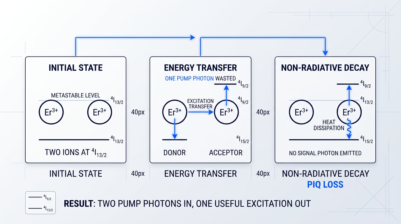
The specific mechanism responsible for gain loss in clustered regions is cooperative upconversion, and its macroscopic consequence is pair-induced quenching (PIQ).
The process works as follows: when two adjacent Er³⁺ ions are both excited to the ⁴I₁₃/₂ metastable level, one ion (the donor) transfers its excitation energy to the other (the acceptor). The donor decays to the ground state (⁴I₁₅/₂), while the acceptor is promoted to the higher ⁴I₉/₂ level.
The acceptor then rapidly decays non-radiatively back down to ⁴I₁₃/₂ without emitting a signal photon — the excess energy is dissipated as heat.
Two pump photons are consumed to excite both ions into the metastable level, but after the cooperative upconversion event only one ion remains there. The second pump photon's energy is lost as heat — absorption without production of an additional signal photon.
PIQ is not a defect to be engineered away — it is a statistical inevitability of ion proximity. As Er³⁺ concentration rises, so does the probability of ion-pair formation, and therefore the fraction of pump power wasted through this mechanism.
Concentration Ceilings by Host Composition
The onset of significant concentration quenching varies substantially depending on the host glass composition. Research from Furukawa Electric and corroborating peer-reviewed sources provide the following approximate thresholds — these are engineering guidelines, not hard limits, and the precise onset depends on the specific glass recipe and fabrication process.
| Host Composition | Approx. Quenching Onset (wt ppm Er) | Key Trade-off |
|---|---|---|
| Pure SiO₂ | ~Several hundred ppm | Severe clustering even at low concentrations; low Er solubility inherent to the host |
| Ge-SiO₂ | Below 100 ppm | Germanium does not improve Er solubility; quenching onset earlier than in pure silica |
| Al₂O₃-SiO₂ | ~1,000 ppm | Al co-doping raises the ceiling significantly; broader, flatter gain spectrum; dominant commercial choice |
| Yb/Er co-doped (core) | Higher than Al-SiO₂ ceiling | Yb acts as ionic buffer reducing Er-Er pair formation; advanced technique, not mainstream |
Comparison of approximate Er³⁺ concentration quenching thresholds and key trade-offs by host glass composition, drawn from Furukawa Electric technical review data and ScienceDirect sources. The Yb/Er row reflects a directional finding only — a specific ppm ceiling is not confirmed by the sources used in this guide.
The pattern in these figures is telling: germanium, despite its widespread use as a refractive index modifier in standard telecom fiber, actively worsens the quenching problem relative to aluminium and is a poor sole co-dopant for high-concentration EDF.
Aluminium raises the usable concentration ceiling by roughly an order of magnitude compared to germanium hosts — a difference that translates directly into the range of amplifier designs that are practically achievable.
Aluminium Co-Doping: The Commercial Standard
Al³⁺ acts as a network modifier in the silica glass matrix, disrupting the regular SiO₂ network structure and creating additional coordination sites where Er³⁺ ions can sit without clustering.
Aluminium ions form a solvent shell around each Er³⁺ ion, improving its solubility in the host and spatially separating erbium ions from one another — directly reducing the probability of ion-pair formation and therefore PIQ.
There is a further benefit relevant to multi-channel applications: aluminium co-doping produces a flatter, broader gain spectrum across the C-band compared to germanium or phosphorus co-doped hosts, making it well-suited to DWDM amplification where uniform gain across many channels is a primary requirement.
This combination of effects — higher concentration ceiling, reduced clustering, and a broader gain spectrum — is why Al-codoped EDF is the dominant commercial choice for EDFA applications. It follows directly from the material physics described above.
Phosphorus and Ytterbium: Narrower Roles
Phosphorus co-doping takes a different approach to the clustering problem. P⁵⁺ ions preferentially bond with Er³⁺, forming structured ErPO₄-like coordination environments that provide a well-defined local geometry around each erbium ion and prevent cluster formation.
However, phosphorus co-doped EDF carries a meaningful trade-off: the gain spectrum is narrower than that of Al-codoped fiber, making it less suited to broadband DWDM applications.
Phosphorus co-doping occupies a specific niche where its coordination chemistry is advantageous, but it is not a general substitute for aluminium co-doping in commercial EDFA design.
Yb³⁺ co-doping serves a different function in this context. When Yb³⁺ ions are introduced into the EDF core alongside Er³⁺ — distinct from the Er/Yb double-clad architecture used in high-power cladding-pumped amplifiers, which is covered separately — they act as an ionic buffer, occupying glass network sites that would otherwise be filled by Er³⁺ ions.
By diluting the local Er³⁺ concentration within the glass structure, Yb co-doping reduces the probability of Er-Er ion-pair formation and PIQ without reducing the total rare-earth doping density, enabling higher Er concentrations than are achievable in Al-SiO₂ hosts alone.
This is an advanced technique rather than a mainstream approach: the primary mitigation strategy for most commercial EDFAs remains aluminium co-doping, and the Yb spatial-buffer role should not be confused with the energy-transfer sensitisation function that Yb serves in high-power amplifier architectures.
Doping Concentration Is a System Variable
The central point of this section is that doping concentration cannot be evaluated in isolation. Co-dopant engineering has raised the concentration ceiling — but that ceiling still matters, and where within it a given EDF sits is determined by the rest of the amplifier design.
A high-concentration fiber achieving a target gain in 2 m may produce a worse noise figure than a lower-concentration fiber achieving the same gain in 6 m, depending on the pump power available and the inversion profile along the fiber.
The right doping level for a given application cannot be read from a catalogue — it requires knowing the target gain, the acceptable noise figure, the pump power budget, and the fiber length, all of which are co-dependent variables.
That interdependence between concentration and length is the subject of the next section, which examines how fiber length and doping level interact to determine the amplifier's gain, noise figure, and saturation behaviour as a unified design space.
Fiber Length and Doping Level: A Co-Dependent Design Variable
Two erbium-doped fibres with very different doping concentrations can be designed to produce identical gain — simply by adjusting fibre length to compensate. That numerical equivalence is real, but it masks a more important truth: the two amplifiers will behave quite differently in terms of noise figure, saturation characteristics, and ASE behaviour.
Treating length as a lookup once doping is fixed is the most common framing error in EDF design — and understanding why requires tracing the gain integral back to its physical foundations.
The reason is straightforward from the gain integral. As the Blumenthal ECE228B lecture notes formalise, gain is computed by integrating the local gain coefficient — itself a product of the local inversion fraction and the doping concentration — along the full fibre length. A lower doping concentration produces a smaller gain coefficient per unit length, but a proportionally longer fibre recovers the same total gain. Doping level and fibre length are therefore coupled through the gain integral, not independently selectable.
This coupling has a hard physical limit: the optimal fibre length. As the Blumenthal notes state explicitly, for a given pump power the amplifier gain becomes maximum at an optimum length, then rolls off sharply as the pump photons have all been absorbed.
The mechanism behind this optimum is worth understanding precisely. Pump power is absorbed progressively along the fibre, and beyond the point where the pump is substantially depleted, the distal section is too weakly pumped to sustain inversion above the transparency threshold — that under-inverted region reabsorbs signal rather than amplifying it.
The optimum is not a design preference; it is a physical consequence of pump depletion. Crucially, both fibre length and pump power must be co-optimised — changing pump power shifts the optimum length, so the two cannot be fixed independently.
C-Band vs. L-Band: A Fundamentally Different Length Regime
Band selection is not merely a wavelength choice — it commits the designer to a fundamentally different length regime. According to the Lightwave Online L-band amplifier analysis, emission and absorption coefficients in the L-band are three to four times smaller than the corresponding C-band values.
The consequence is directly quantified: L-band amplifiers using standard erbium-doped silica fibre require coil lengths that are four to five times longer than a comparable C-band design delivering the same gain.
L-band amplifiers also operate at substantially lower average inversion. The Lightwave L-band analysis reports that L-band designs typically operate at around 40% average inversion, compared with 60–65% for C-band amplifiers — a difference that has cascading consequences for both gain spectrum and noise performance.
Lower average inversion in L-band operation degrades noise figure performance — approximately 1 dB worse than comparable C-band amplifiers in demonstrated prototypes — and reduces pump conversion efficiency because pump power is more readily absorbed before reaching the output end of the longer coil.
The longer coil also accumulates more backward ASE, which further erodes inversion at the input end and pushes noise figure higher. L-band design therefore requires careful management of both fibre length and pump architecture simultaneously — the length penalty is not simply a packaging inconvenience.
Saturation Behaviour and Amplifier Stage Selection
Doping level shapes not just gain per unit length but also how the amplifier saturates. RP Photonics notes that the saturation energy of an EDFA is relatively large compared with semiconductor optical amplifiers — typically several microjoules even for small mode-area fibres — owing to the small transition cross-sections of Er³⁺ in silica glass hosts.
A shorter, more highly doped fibre holds fewer total excited ions at any given moment than a longer, lightly doped fibre delivering the same gain. With a smaller reservoir of inverted ions, gain compression sets in at lower signal powers — the effective saturation energy is reduced.
This directly governs which amplifier stage a given fibre is suited to. Booster amplifiers require high output saturation power; a shorter, highly doped fibre — with its lower saturation energy — is less well suited to this role than a lightly doped, longer fibre that sustains gain at higher output powers.
Noise Figure, Pump Direction, and Inversion Profile
Noise figure is not a fixed property of a given fibre — it depends on how the fibre is operated. The Blumenthal ECE228B notes are explicit: noise figure increases with increasing fibre length and decreases with increasing pump power, and low noise figure close to 3 dB can be achieved for high gain when pump power is well above the saturation threshold.
When fibre length exceeds the optimum, the weakly pumped distal region contributes reabsorption loss that degrades noise figure directly. The RP Photonics tutorial on fibre amplifier noise confirms that backward pumping produces a higher noise figure than forward pumping because the inversion level near the signal input end is low in that configuration — and it is inversion at the input end that is most sensitive to noise figure penalty.
The Lightwave Online modelling article makes the design lever explicit: forward pumping is preferred to maintain a low noise figure, while backward pumping is preferred to achieve high output power. Pump direction and fibre length interact to shape the inversion profile along the fibre, and the engineer controls both.
The net gain spectrum of an EDF shifts with average inversion level: high inversion favours the short-wavelength gain peak near 1530 nm, while lower inversion — produced by a longer fibre, reduced pump power, or L-band operating conditions — shifts the gain maximum progressively toward longer wavelengths. The gain spectrum delivered to the signal is determined by the interplay of doping, length, and pump power, not fixed at manufacture.
RP Photonics confirms this from first principles: the spectral shape of the gain is substantially influenced by the average degree of excitation of the erbium ions, because the transition is quasi-three-level in character. The Lightwave modelling article notes that L-band designs make deliberate use of this effect, operating at low average inversion to access the longer-wavelength gain region.
For DWDM designers, the practical consequence is that gain flatness is sensitive to operating conditions — a shift in pump power, signal loading, or fibre length that alters average inversion will tilt the gain spectrum and affect channel uniformity across the band.
The design implication of everything above is that selecting a doping level in isolation produces an underspecified amplifier. The Lightwave modelling article frames the engineering practice correctly: the optimum length of each gain stage is found by iterating between fibre length, filter shape, and pump power — not by fixing one parameter and reading off the others from a datasheet. Doping concentration, fibre length, pump power, and target gain spectrum are a system of coupled variables to be co-optimised together.
The inversion profile that results from these choices — varying longitudinally along the fibre as pump power depletes and signal power builds — is also the quantity that governs amplified spontaneous emission generation and its directional asymmetry, which the next section addresses directly.
Amplified Spontaneous Emission: Origin and Design Consequences
Every design decision that makes erbium-doped fiber an effective gain medium — high population inversion, long interaction length, tight mode confinement — simultaneously creates the conditions for amplified spontaneous emission (ASE). ASE is not a defect to be eliminated; it is an inescapable physical companion to gain, and understanding its behaviour is what separates a well-engineered amplifier from one that hits an unexplained performance ceiling.
The mechanism is straightforward: once erbium ions are excited into the ⁴I₁₃/₂ metastable level, a fraction undergo spontaneous emission regardless of whether a signal is present — this process cannot be gated or suppressed.
A small portion of those spontaneously emitted photons couples into the fiber core's guided modes and propagates along the fiber length, experiencing the same gain medium as the signal and being amplified by stimulated emission in exactly the same way — hence the name.
The spectral shape of ASE in EDF is governed by the gain spectrum, which itself depends on the local inversion level. At high inversion — typical of C-band amplifiers — ASE peaks near 1530 nm, where the emission cross-section is largest, and spans the entire gain bandwidth rather than occupying a narrow channel.
At lower inversion levels, as encountered in L-band operation or in the weakly pumped distal region of a long fiber (both established in the preceding section), shorter-wavelength ASE is preferentially reabsorbed, shifting the effective ASE peak toward longer wavelengths.
ASE is not a passive bystander in this process. It actively competes with the signal for the stored energy in the inversion, saturating the gain medium in the same way a strong signal would and progressively extracting power that would otherwise amplify the desired channel.
This gain saturation by ASE imposes a practical ceiling on achievable single-stage gain. When the gain exceeds roughly 30 dB, ASE begins to become substantial; above approximately 40 dB, ASE can extract a power comparable to the available pump power, making further single-stage gain increasingly inefficient.
For any phase-insensitive optical amplifier operating at high gain, quantum optics sets an absolute minimum noise figure of 3 dB — corresponding to a noise factor of exactly 2. No physical mechanism providing phase-insensitive amplification can beat this limit. Quasi-three-level amplifiers like EDFAs, where reabsorption at the signal wavelength demands higher upper-state population for a given gain, inherently operate above it.
The directional behaviour of ASE is one of the less intuitive but practically significant aspects of EDF physics. In a co-pumped (forward-pumped) configuration, the distal end of the fiber — furthest from the pump input — is weakly inverted and sits near or below the transparency threshold.
This weakly pumped region seeds backward ASE: spontaneous emission generated there propagates back toward the high-inversion input end, where it encounters the strongest gain and is amplified most efficiently. The result is that backward ASE is typically substantially stronger than forward ASE in a co-pumped EDFA — a direct consequence of the inversion gradient along the fiber length.
This directional asymmetry has practical implications for isolator placement; it also means that the choice of pump architecture directly shapes the ASE power balance between the two propagation directions.
ASE copropagating with the signal degrades the optical signal-to-noise ratio (OSNR), and the noise figure is the fundamental metric for quantifying this degradation. The quantum-limited noise figure for a high-gain, fully inverted phase-insensitive amplifier is 3 dB — a limit imposed by quantum optics that applies to any amplification mechanism, not just stimulated emission.
EDF's quasi-three-level nature means complete inversion is never achieved at the signal input end: some ground-state absorption always persists at the signal wavelength, requiring a higher upper-state population to achieve a given gain, which in turn drives stronger spontaneous emission and pushes practical noise figures above the 3 dB floor.
This is precisely why 980 nm forward pumping — discussed in the pump wavelength section — minimises noise figure: it maximises inversion at the fiber's input end, where ASE seeding begins and where excess noise has the greatest impact on the total noise figure.
ASE, EDF Material Parameters, and Design Consequences
The severity of ASE in a given amplifier design is not fixed — it is shaped directly by the EDF's material parameters, and understanding these connections is what allows engineers to use fiber selection as a design lever.
- Doping concentration and fiber length: Higher-concentration fibers are shorter for a given gain, reducing the total propagation length over which ASE accumulates — a practical advantage for compact, low-ASE amplifier designs.
- Average inversion level: L-band operation at lower average inversion (~40% across a longer fiber) worsens backward ASE and degrades noise figure, as reabsorption at shorter wavelengths is stronger and the weakly inverted region is more extensive.
- Pump direction and inversion profile: The pump architecture determines how inversion is distributed along the fiber length, which in turn governs the directional balance between forward and backward ASE powers.
- Quasi-three-level reabsorption: Incomplete inversion at the signal input — inherent to EDF's quasi-three-level transition — raises the spontaneous emission factor and sets the noise figure above the 3 dB quantum limit.
When single-stage gain requirements exceed the practical ASE-saturation ceiling, the engineering response is a multi-stage amplifier architecture: the amplifier is split into two or more stages, with a narrowband optical bandpass filter inserted between them.
The inter-stage filter suppresses the broadband ASE generated in the first stage before it enters the second, preventing it from being amplified into a large ASE power load that would saturate the second stage and degrade the total system noise figure. This architecture is not an arbitrary design preference — it is the direct engineering consequence of EDF's ASE physics.
Accurately modelling and managing ASE for a specific erbium-doped fiber requires more than the general principles covered here — it requires the fiber's spectroscopic parameters: the emission cross-section spectrum (which determines the ASE gain shape as a function of inversion level) and the metastable lifetime (which governs energy storage and saturation energy). Those parameters, and why lot-specific measured data is essential for precision amplifier design, are the subject of the next section.
EDF Characterisation: What the Datasheet Must Tell You
A datasheet tells you what a fiber nominally is. What precision amplifier design actually requires is measured data for the specific lot you are buying — and those two things are not the same.
The spectroscopic parameters that govern EDFA performance vary from batch to batch, even from high-quality manufacturers. When engineers use nominal datasheet values as modelling inputs rather than measured lot-specific data, every subsequent calculation — optimal fiber length, pump power, noise figure, saturation energy — inherits that error and compounds it.
Absorption Cross-Section (σ_abs)
The absorption cross-section (σ_abs) is the wavelength-dependent probability that an Er³⁺ ion in the ground state absorbs a photon — quantified as the rate of absorption transitions per ion, per unit photon flux density.
It governs two things simultaneously: how efficiently a given fiber lot converts pump power into population inversion at 980 nm or 1480 nm, and how strongly the fiber reabsorbs signal photons across the gain band.
The primary datasheet parameters for σ_abs are its measured values at 980 nm and at 1530 nm — the pump absorption peak and the signal absorption peak respectively. These are not interchangeable: the 980 nm value determines pump efficiency, while the 1530 nm value sets the reabsorption floor that the amplifier must overcome to produce net gain.
Because σ_abs enters directly into the rate equations that govern population inversion, a shift of even a few percent in its measured value changes the pump power required to achieve a target inversion level — and therefore changes the optimal fiber length for a given gain target.
Emission Cross-Section (σ_em)
The emission cross-section (σ_em) is the wavelength-dependent probability that an excited Er³⁺ ion emits a photon via stimulated emission. Together with σ_abs, it determines the net gain coefficient at every wavelength across the signal band.
The net gain at any wavelength is the balance between stimulated emission (driven by σ_em and the excited-state population) and reabsorption (driven by σ_abs and the ground-state population) — a balance that shifts with inversion level.
The emission peak sits at a slightly longer wavelength than the absorption peak, a consequence of the Boltzmann thermal distribution across the Stark sublevels of the ⁴I₁₃/₂ manifold: at room temperature, higher sublevels of the excited manifold are thermally populated, and transitions from those sublevels to the ground state emit at longer wavelengths.
This wavelength shift is not merely a curiosity. It is precisely why EDF can provide net gain in the C-band without complete reabsorption at the gain peak: the emission cross-section at 1530 nm is high enough to overcome reabsorption when the fiber is sufficiently inverted, while at wavelengths approaching 1560–1565 nm the emission-to-absorption ratio is more favourable and net gain is achievable at lower inversion levels.
Emission cross-sections are typically derived from fluorescence spectra using the Füchtbauer-Ladenburg equation, or calculated from absorption cross-sections via the McCumber relation — both well-established measurement methodologies in the EDF characterisation literature.
Metastable State Lifetime (τ)
The metastable state lifetime (τ) is the fluorescence lifetime of the ⁴I₁₃/₂ level — the upper laser level from which stimulated emission occurs. In silica-based EDF, this lifetime is typically in the range of 8–10 ms.
τ governs three coupled design quantities: the energy storage capacity of the fiber, the saturation energy of the amplifier, and the timescale over which gain responds to changes in pump or signal power.
A longer τ means more energy can be stored in the excited-state population before stimulated or spontaneous emission depletes it — which is why EDFAs exhibit relatively high saturation energies compared to semiconductor optical amplifiers, and why gain dynamics are slow (on the order of milliseconds) rather than nanoseconds.
Measurement is straightforward in principle: the pump is modulated and the exponential decay of fluorescence intensity is observed, yielding τ directly from the decay constant. In practice, lot-to-lot variation in τ of hundreds of microseconds is physically real and consequential — it shifts the saturation energy, alters dynamic gain behaviour under signal transients, and changes the steady-state inversion profile at a given pump power.
Lot-to-Lot Variation and Modelling Consequences
The case for lot-specific characterisation data is not a critique of manufacturer quality — it is a statement about the physics of precision amplifier design.
Even small parameter variations that fall comfortably within a manufacturer's published specification range are sufficient to shift the optimal fiber length for a target gain, alter the pump power required to reach a target inversion level, and change predicted noise figure and saturation behaviour.
When nominal datasheet values are used as inputs to amplifier simulation tools, the model is calibrated to a statistical average, not to the actual fiber in the build. Every downstream prediction inherits the mismatch between nominal and measured values, and those errors compound: a small error in σ_abs propagates into an error in the inversion profile, which propagates into an error in the gain spectrum, which propagates into an error in the gain-flattening filter design.
OFS explicitly acknowledges this in their product documentation: their OASiX amplifier simulation software includes modelling parameters specific to the lot of EDF purchased — a direct acknowledgement that lot-specific measured data, not nominal values, is the correct input for accurate EDFA simulation.
Peak Absorption at 1530 nm: The Procurement Anchor
Peak absorption at 1530 nm, stated in dB/m, is the most universally specified parameter on EDF datasheets and the primary procurement specification for amplifier designers.
Its practical role is direct: it determines the fiber length required to achieve a specified total absorption, which is the first-order input to amplifier length optimisation. A fiber with higher peak absorption at 1530 nm achieves the same total absorption in a shorter length — with all the downstream consequences for inversion profile, ASE accumulation, and gain bandwidth that earlier sections have established.
Corning's ER Specialty fiber documentation specifies batch variation around peak absorption at ≤ ±1% per batch across their C-band EDF product range — with peak absorption ranges spanning 5.0 to 10.0 dB/m at 1530 nm depending on fiber type, and L-band variants reaching 18.0 to 29.0 dB/m.
That ±1% batch reproducibility figure is the quality metric that enables consistent amplifier performance without re-qualification across fiber lots. When batch-to-batch variation is tighter, the engineer can rely on the characterisation data from one lot to remain valid for the next — a critical requirement in volume manufacturing of DWDM amplifiers.
Coherent's EDFL-980-HP datasheet illustrates the contrast between nominal specification and lot-specific precision: core absorption near 1530 nm is specified at 25.0 ± 2.0 dB/m, while at 980 nm the tolerance widens to 18.5 ± 11.5 dB/m — a range that underscores why measured lot data at both wavelengths is necessary for accurate pump efficiency modelling.
Gain Shape Across Inversion Levels
The gain shape of an erbium-doped fiber is not a fixed property of the material — it is a function of the average inversion level, which is itself determined by fiber length, doping concentration, and pump power.
At high inversion levels, the gain peak sharpens around 1530 nm. At lower inversion levels, the gain maximum shifts toward longer wavelengths — toward 1560–1565 nm — because reabsorption at shorter wavelengths is relatively stronger when fewer ions are excited.
This inversion-dependence of gain shape has a direct consequence for DWDM system design: a gain-flattening filter (GFF) must be designed for the specific gain spectrum the amplifier will produce at its operating inversion level, not for a generic EDF gain curve.
Characterisation data that maps gain shape across a range of inversion levels — derived from measured σ_abs and σ_em spectra — gives the designer the input needed to model and pre-compensate spectral gain variation before committing to a GFF design. Without it, the filter is designed to a curve that may not match the actual fiber's behaviour at the operating point.
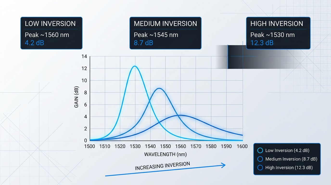
The inversion level at which a given amplifier operates is a design choice — set by the combination of fiber length, doping, and pump power established in earlier design stages. The characterisation data is what allows the engineer to model the spectral consequences of that choice and design the GFF accordingly.
Engineers specifying EDF for precision amplifier builds should always request measured absorption cross-sections, emission cross-sections, and metastable state lifetime for the specific fiber lot being purchased. Suppliers including Corning, Coherent, and OFS provide lot-specific characterisation data on request or as part of product documentation — treat this as a procurement requirement, not an optional extra.
With the spectroscopic parameters in hand, the next practical consideration is how the fiber integrates physically into the amplifier assembly — and where splice compatibility can quietly undermine the gain advantage of a well-characterised fiber.
Custom EDFAs Built Around Your Exact Requirements
Datasheets give you nominal values. Our custom EDFAs are built to specification around your gain target, noise figure budget, and deployment constraints, and our engineers assess your requirements with you.

Splice Compatibility and Integration Considerations
A 0.1 dB splice loss that would be invisible in a long-haul transmission span becomes a meaningful fraction of your gain budget the moment you are working with a few metres of erbium-doped fiber.
In passive transmission systems, splice events are amortised across kilometres of fiber; any individual joint contributes a negligible penalty to end-to-end performance.
EDF operates in an entirely different regime: a standard C-band amplifier uses perhaps 3–10 m of active fiber, and a high-concentration design may use as little as 1–2 m.
At those lengths, a 0.1–0.2 dB splice loss at each end of the EDF is a direct tax on the gain budget — degrading noise figure and reducing output power in ways that cannot be recovered downstream.
This is why integration compatibility must be evaluated at the fiber selection stage, not resolved during assembly.
Mode Field Diameter Mismatch and Thermal Diffusion
The dominant intrinsic loss mechanism when splicing EDF to standard passive fiber is mode field diameter (MFD) mismatch.
EDF cores are typically smaller and carry a higher refractive index contrast than standard SMF-28, which has an MFD of approximately 10.5 µm at 1550 nm — a direct consequence of the waveguide geometry required for efficient pump-signal overlap in the doped core.
When two fibers with differing MFDs are fusion-spliced, the coupling efficiency follows the form (4w₁²w₂²)/(w₁²+w₂²)² for Gaussian mode profiles: efficiency falls as the ratio of the two mode radii departs from unity, making MFD mismatch a predictable and quantifiable design challenge.
To illustrate the scale of this mismatch with a real product: the nLIGHT Liekki ER80-8/125 has an MFD of 9.5 ± 0.5 µm at 1550 nm and a core NA of 0.13 — already relatively close to SMF-28 compared with the smaller-core, higher-NA variants in the same family.
Smaller-core EDF products, such as the 4/125-geometry fibers with NA values around 0.2 and MFDs of approximately 6.5 µm at 1550 nm, present a more pronounced geometric mismatch to SMF-28 and would incur higher intrinsic splice loss if the splice were treated as a simple butt-joint.
In practice, however, aluminium-codoped EDF — the dominant commercial type — offers a physical mechanism that substantially reduces achieved splice loss below what geometry alone would predict.
The high alumina content in Al-codoped EDF causes dopant diffusion during arc fusion that expands the mode field at the splice interface in situ. Corning's C-band ER Specialty fibers achieve typical splice loss to SMF-28e+ of just 0.10–0.13 dB — a result that is physically impossible without this diffusion effect, and only reachable with EDF-optimised splicer parameters.
This thermal diffusion effect works because aluminium ions migrate outward more readily than germanium under arc heat, broadening the refractive index profile and expanding the guided mode at the joint — acting as a natural, in-situ mode field adapter.
The effect rewards careful splicer parameter optimisation: arc power and duration must be tuned for the specific EDF type to maximise the beneficial diffusion without over-fusing the fiber.
Default SMF-28 splice programmes do not achieve this, and using them will leave significant splice loss unrealised — the optimised figures cited by manufacturers assume EDF-specific settings, not generic passive-fiber programmes.
Numerical Aperture and Cut-Off Wavelength Checks
Numerical aperture (NA) mismatch is a related but distinct contributor to splice loss and pump coupling efficiency.
EDF typically carries a higher NA than standard SMF: Corning's C-band ER Specialty products specify NA values of 0.22–0.23, while individual OFS RightWave C-band EDF products show NA values of 0.24, 0.26, and 0.32 depending on the specific fiber type — all substantially above the ~0.13 of SMF-28.
In core-pumped amplifier configurations, the NA of the EDF relative to the pump delivery fiber directly affects how efficiently pump light couples into the doped core: a pump delivery fiber with a lower NA than the EDF will couple efficiently, whereas the reverse wastes pump power.
NA compatibility with the pump delivery fiber is therefore a parameter to specify explicitly at the design stage, not something to verify after the amplifier is assembled.
The cut-off wavelength of the EDF is the third specification to verify before purchase, and it is the one most likely to be overlooked.
The fiber's cut-off wavelength defines the shortest wavelength at which only the fundamental mode propagates; below that threshold, higher-order modes are also guided.
If the cut-off wavelength exceeds the pump wavelength, the EDF supports higher-order pump modes — modes with different spatial overlap with the doped core than the fundamental, which degrades pump absorption efficiency and introduces multipath interference.
This constraint is most critical for 980 nm pumping, where the margin between cut-off and pump wavelength is smallest: a fiber with a cut-off above 980 nm will be multimode at the pump wavelength regardless of its signal-wavelength behaviour.
The OFS RightWave 80 µm EDF explicitly specifies a cut-off below 980 nm to minimise multipath interference risk — a specification that reflects deliberate design intent for low-noise 980 nm-pumped applications.
For 1480 nm pumping the cut-off constraint is less acute, but it still applies: the cut-off must remain below 1480 nm to guarantee fundamental-mode pump propagation.
Taken together, these four integration parameters form a practical checklist that belongs alongside spectroscopic parameters in any EDF evaluation.
- Splice loss to passive fibers: Verify typical splice loss to each passive fiber in the assembly — coupler fiber, pump combiner pigtail, isolator fiber — using EDF-optimised splicer parameters, not default SMF-28 programmes.
- Splicer parameter optimisation: Obtain or develop arc power and duration settings specific to the EDF type to fully realise the thermal diffusion benefit of aluminium-codoped fiber.
- Pump delivery fiber NA: Confirm the pump delivery fiber NA is equal to or lower than the EDF core NA to ensure efficient pump coupling without power loss at the joint.
- Cut-off wavelength against pump: Check the EDF cut-off wavelength is below the pump wavelength — below 980 nm for 980 nm-pumped designs — before ordering, not during commissioning.
When two EDF candidates show similar spectroscopic performance — comparable absorption cross-section, metastable lifetime, and gain spectrum — integration compatibility becomes the differentiator that determines which fiber actually delivers better net amplifier performance.
A fiber with marginally lower peak absorption but significantly lower splice loss to the assembly's passive components may outperform a nominally superior fiber that is difficult to splice or requires a pump delivery fiber redesign.
The integration considerations covered here apply differently across the principal EDF variant families — PM-EDF, radiation-hardened fiber, and large-mode-area designs each bring their own splice compatibility characteristics, which the next section examines in detail.
EDF Variants: PM, Radiation-Hardened, and LMA Designs
Every variant covered in this section starts from the same gain medium physics the guide has established — the same Er³⁺ energy levels, the same 1530–1610 nm emission band, the same metastable lifetime. What differs is that each variant makes a deliberate structural or compositional sacrifice to meet a constraint that standard single-mode EDF simply cannot satisfy. Understanding those sacrifices is what separates informed EDF selection from catalogue browsing.
Polarisation-Maintaining EDF
PM-EDF combines the gain properties of standard erbium-doped fiber with a strong, built-in birefringence that preserves the linear polarisation state of light propagating along the fiber — a property required in coherent optical communications (where phase-diversity detection at the receiver is sensitive to polarisation state), fibre-optic gyroscopes (where Sagnac interference demands polarisation stability throughout the sensing coil), and polarisation-sensitive laser cavities.
The birefringence is created structurally, not by eliminating asymmetry, but by deliberately introducing a large, well-defined one. The two dominant designs are PANDA and bow-tie. In PANDA fiber, two circular stress rods of boron-doped glass are placed on opposite sides of the core; when the fiber is drawn, the differential thermal contraction between those rods and the surrounding silica creates a permanent mechanical stress field that splits the propagation constants of the two polarisation modes.
Bow-tie fiber uses sector-shaped stress-applying parts fabricated by chemical vapour deposition, which reach closer to the core and can achieve higher birefringence — at the cost of greater manufacturing complexity. PANDA's circular geometry offers better core concentricity and wider compatibility with standard PM fusion splicers, yielding lower splice loss; bow-tie designs deliver stronger birefringence, making them more robust in mechanically or thermally demanding environments where PANDA's birefringence margin might be insufficient.
- Beat Length: The propagation distance over which the polarisation state completes one full cycle. Shorter beat length means stronger birefringence.
- Polarisation Extinction Ratio (PER): The ratio of power in the intended polarisation state to power in the orthogonal state, expressed in dB.
These two metrics govern PM-EDF selection independently of the standard spectroscopic parameters. An amplifier built with PM-EDF that has an inadequate beat length for its operating environment will degrade polarisation extinction ratio along the gain length, defeating the purpose of using PM fiber at all. PM-EDF does not offer higher gain than standard EDF — gain performance is otherwise comparable — and the added splice complexity means it is the right choice only when the application genuinely requires polarisation maintenance.
Radiation-Hardened EDF
When an erbium-doped fiber is exposed to ionising radiation — gamma rays, protons, or solar particles — the radiation interacts with the silica glass network and creates point defects known as colour centres. These defects introduce optical absorption bands that increase loss at both pump and signal wavelengths, progressively degrading amplifier gain over time; this is the mechanism of radiation-induced attenuation (RIA).
The particular vulnerability of standard EDF lies in its co-dopant profile. Aluminium and phosphorus are added to standard EDF specifically to increase erbium solubility, suppress clustering, and improve gain performance — but Al-related and P-related defects are among the most radiation-sensitive structural sites in the silica network, as confirmed by the Southampton Optics Express study (Zhai et al., 2023), which observed that Ce-free aluminosilicate EDF exhibited extremely high RIA under gamma irradiation due to Al-related colour centres.
The aluminium and phosphorus co-dopants that make standard EDF an excellent telecom gain medium — improving erbium solubility and gain bandwidth — are the same dopants that generate the most radiation-sensitive defects in the glass network. Any radiation-hardening strategy must navigate this tension directly.
Three principal mitigation approaches have been demonstrated. Cerium co-doping is the most studied: Ce³⁺/Ce⁴⁺ acts as a redox buffer, passivating radiation-induced defects before they accumulate. The Southampton study showed that Ce co-doped aluminosilicate EDF suppresses RIA by more than an order of magnitude compared to Ce-free EDF, with 4.8 wt% Ce co-doped fiber retaining 41.6 ± 2.9 dB gain in the C-band even after 10 kGy of gamma irradiation — the highest post-irradiation gain reported for a C-band EDFA at that dose level.
Two further approaches address the problem at the material and structural level. Hydrogen or deuterium pre-loading introduces H₂ or D₂ into the fiber glass matrix prior to deployment, passivating defect precursor sites and reducing RIA onset — with the Exail literature demonstrating that gas-loaded fibers combined with Ce co-doping can yield EDFA gain degradation of less than a few percent after 500 Gy. Hole-assisted carbon-coated (HACC) fiber structures retain the gas within the fiber over mission-relevant timescales by slowing out-diffusion at room temperature by a factor of more than 100, making gas loading a practical option for long-duration space deployments.
For satellite and deep-space missions with lifetimes measured in decades, the relevant figure of merit is radiation-induced gain variation (RIGV), expressed in dB/kRad and measured in amplifier configuration rather than as a passive fiber attenuation measurement. RIGV in amplifier configuration is the appropriate metric because gain saturation effects can partially compensate for RIA in some operating regimes — passive fiber RIA alone overstates the practical gain penalty. Exail's space-grade Er-doped fiber, for instance, specifies gain degradation of less than 0.25 dB per 100 krad in a 30 dB gain EDFA configuration.
Large-Mode-Area EDF
Large-mode-area (LMA) EDF addresses a different class of constraint: the onset of nonlinear optical effects at high signal powers. By using larger core diameters and reduced numerical aperture compared to standard single-mode EDF, LMA designs increase the effective mode area (Aeff), reducing the optical intensity within the core for a given signal power and thereby raising the threshold for nonlinear processes — specifically stimulated Raman scattering (SRS), stimulated Brillouin scattering (SBS), and four-wave mixing.
The Coherent LMA application literature demonstrates this scaling concretely: for Yb-doped LMA fiber, moving from a 5 µm core (0.15 NA) to a 30 µm core (0.06 NA) increases the SBS threshold from approximately 39 W to 676 W — a direct illustration of the nonlinear threshold improvement that motivates LMA design for high-power continuous-wave amplifiers and high-energy pulsed systems including ultrashort pulse amplification.
LMA designs carry genuine trade-offs on both sides. The larger core reduces the overlap integral between the optical mode and the erbium-doped region, meaning fewer signal photons interact with excited Er³⁺ ions per unit length and gain efficiency falls. Splice loss to standard SMF increases due to mode field diameter mismatch — the same mechanism discussed in the preceding section on splice compatibility. And as core diameter grows, maintaining truly single-mode guidance becomes harder: LMA designs must carefully balance core size and NA to suppress higher-order mode propagation, or rely on controlled launch conditions and coiling to strip unwanted modes.
For high-power cladding-pumped operation, LMA EDF is frequently fabricated as a double-clad fiber with an Er/Yb co-doped core and a large inner cladding that accepts multimode pump light from high-brightness diode sources. Yb³⁺ co-doping is essential in this architecture: Yb³⁺ has a substantially larger absorption cross-section at 915–976 nm than Er³⁺, so it absorbs the pump efficiently and transfers energy to Er³⁺ via resonant energy transfer — enabling cladding-pumped operation that would be impractical with erbium alone. Coherent's PM LMA Er/Yb fiber, for example, uses a 25 µm core and 300 µm cladding diameter with a low core NA of approximately 0.09, achieving slope efficiencies of 30–40% in nanosecond pulsed amplification.
High-Concentration Short-Length EDF
The fourth variant type responds not to a physical deployment hazard but to a footprint and integration constraint. Very high erbium doping levels — exemplified commercially by the nLight LIEKKI Er110-4/125 at 110 dB/m peak absorption at 1530 nm and the Er80-8/125 at 80 dB/m — enable C-band application lengths of approximately 0.6 m and 0.9 m respectively, compared to several metres for standard-concentration EDF. The shorter fiber reduces device footprint, lowers total nonlinear phase accumulation, and simplifies compact amplifier packaging.
The trade-off connects directly to the concentration quenching and pair-induced quenching mechanisms covered earlier in this guide. As erbium ion density increases, the average distance between neighbouring Er³⁺ ions decreases, raising the probability of ion-ion energy transfer that depopulates the upper laser level non-radiatively and degrades power conversion efficiency. Pushing doping levels to 80–110 dB/m requires careful co-dopant optimisation — aluminium co-doping to improve erbium solubility and suppress clustering, and in some architectures ytterbium co-doping to assist energy transfer — to maintain acceptable efficiency without the quenching losses that would otherwise accompany such high ion densities.
High-concentration short-length EDF is particularly suited to space-constrained deployments, rack-mounted amplifier modules with tight form factors, and pulsed systems where minimising fiber length reduces both dispersion and nonlinear phase accumulation. With the four principal EDF variants now characterised as engineering trade-offs, the next section maps each variant to the specific deployment contexts where those trade-offs resolve in its favour.
EDF Material Requirements by Application
The material science covered across this guide was never abstract — every parameter, every trade-off, every variant exists because real deployment environments impose real constraints on the fiber. With that vocabulary now established, it becomes possible to read each application context not as a list of requirements but as a direct consequence of spectroscopic, geometric, and environmental properties: the same properties you have just spent the guide learning to evaluate.
DWDM Terrestrial Systems
The defining EDF demand in dense wavelength division multiplexing (DWDM) terrestrial systems is gain flatness across the C-band, and increasingly across C+L combined — because gain imbalance between channels compounds across every amplifier in a cascaded chain, ultimately limiting transmission distance and channel count.
This is precisely why aluminium co-doped EDF dominates DWDM amplifier builds: as covered in the dopant concentration section, Al co-doping broadens and smooths the erbium gain spectrum, enabling spectrally flat gain over the full C-band without the deep trough near 1540 nm that characterises germanium-only hosts.
Gain flatness is sensitive to doping level, fiber length, and population inversion level — and it is calibrated against a specific gain-flattening filter (GFF) designed for a particular fiber's gain shape. A batch change that shifts the absorption cross-section profile, even modestly, can force re-qualification of the GFF across the entire amplifier design.
This is the practical consequence of the argument made in the characterisation section: lot-to-lot spectroscopic consistency is not a procurement nicety in DWDM — it is a system reliability requirement, because the GFF is designed to the fiber's measured gain curve, not to a nominal datasheet value.
High erbium concentration also matters here for a second reason: as discussed in the fiber length and doping section, higher-concentration EDF enables shorter active fiber lengths, which directly reduces the accumulation of nonlinear impairments in high-channel-count systems where total signal power is substantial.
Submarine Cable Systems
Submarine amplifier architecture is defined by a single structural constraint: there is no power available on the seabed. Pump light must travel from a shore terminal through the transmission fiber itself to reach the submerged erbium-doped fiber segment — the remotely pumped amplifier (ROPA) architecture.
The choice of 1480 nm pump wavelength for remote pumping follows directly from the pump wavelength section: at 1480 nm, silica fiber attenuation is lower than at 980 nm, allowing sufficient pump power to survive the long propagation distance from shore to the submerged EDF block — a physical constraint that makes 980 nm impractical for this architecture.
Reliability requirements in submarine systems are extreme: ITU-T G.977 specifies a 25-year design life, with fewer than three cable-ship interventions permitted over that period — a standard that demands failure rates for submerged components orders of magnitude lower than equivalent terrestrial equipment.
At depth, hydrogen ingress is the primary material threat to EDF performance. Molecular hydrogen diffuses through conventional polymer coatings and into the fiber core, where it forms hydroxyl (OH) units in the glass — increasing passive loss in the short-wavelength region of the erbium gain band and reducing gain efficiency by creating a competing energy transfer pathway from the Er ⁴I₁₃/₂ level to OH bonds.
The engineering response is a hermetic carbon coating applied during the fiber draw, before the polymer jacket — a layer typically around 50 nm thick that is impermeable to molecular hydrogen and water. Corning has documented that hermetically coated EDF shows no measurable hydrogen-induced loss after extended exposure under high hydrogen pressure, and has used this approach in long-haul undersea applications since 1992.
CATV and FTTH High-Power Applications
Cable TV and fibre-to-the-home distribution networks require watt-class continuous-wave output power — a regime that single-clad, core-pumped EDF cannot reach, because the pump power that can be coupled into a single-mode core is limited by the output of single-mode pump diodes.
The solution, as introduced in the EDF variants section, is the Er/Yb co-doped double-clad fiber (EYDFA) architecture: a large multimode pump cladding accepts high-power multimode diodes at 915 nm or 940 nm, while ytterbium absorbs the pump and transfers energy resonantly to neighbouring erbium ions, which provide gain at 1550 nm. A single 10 W pump diode driving a few metres of Er:Yb double-clad fiber can deliver watt-level 1.55 µm output — sufficient to feed 20 or more passive split outputs from a single amplifier module.
A critical material requirement specific to this architecture is suppression of parasitic 1 µm ASE: under strong pumping, ytterbium ions can lase or emit spontaneously at ~1 µm rather than transferring energy to erbium, wasting pump power and generating noise that must be managed. Pump wavelength selection — specifically 940 nm, which sits at a minimum of the Yb absorption spectrum — is one primary mitigation, reducing the tendency for parasitic Yb emission compared with pumping at the 976 nm peak.
For volume manufacturing of CATV amplifier modules, lot-to-lot reproducibility of the Er:Yb fiber is a production-line requirement: each module must deliver specified output power within tight tolerances, and batch variation in Yb absorption or Er/Yb energy transfer efficiency translates directly into yield loss.
Aerospace and Space Applications
In space, ionising radiation — protons, gamma rays, and solar particles — generates colour centres in the fiber core that increase attenuation at both pump and signal wavelengths, degrading amplifier gain progressively over mission lifetime. Standard EDF is particularly vulnerable because the Al or P co-dopants used to enhance gain also create sites susceptible to radiation-induced defect formation.
The figure of merit for space-grade EDF is radiation-induced gain variation (RIGV) per unit dose, expressed in dB/kRad. Exail's radiation-hardened Er/Yb double-clad fiber achieves RIGV below 0.02 dB/kRad at 1560 nm — enabling amplifier designs that remain within specification across the accumulated dose of demanding missions, including those to the outer planets.
The hardening strategies covered in the variants section — Ce co-doping, H₂/D₂ pre-loading, and hole-assisted carbon-coated (HACC) fiber structures — each act by passivating radiation-induced defects or by maintaining low residual attenuation at signal and pump wavelengths throughout the mission dose profile.
Coherent free-space optical (FSO) communication links from space also require PM-EDF in the amplifier chain, because polarisation state must be preserved through amplification to maintain coherent detection sensitivity — connecting the PM-EDF content from the variants section directly to this operational requirement.
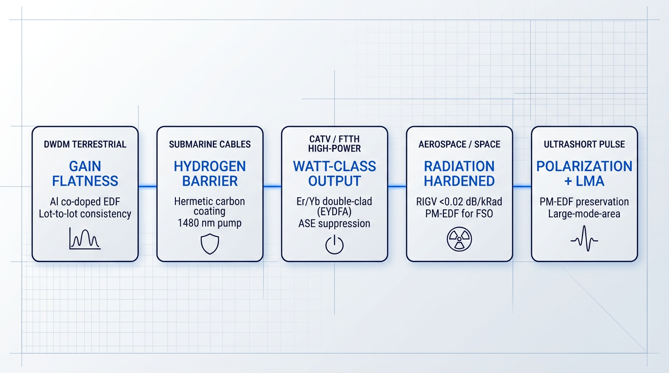
Ultrashort Pulse and Sensing Applications
Fibre lasers, coherent sensing systems, and ultrashort pulse amplifiers impose two material requirements that the earlier variants section addressed directly: polarisation maintenance through the amplifier chain, and a nonlinear threshold high enough to accommodate the peak powers involved.
PM-EDF meets the polarisation requirement by preserving the signal's polarisation state through amplification — essential wherever downstream components (modulators, interferometers, coherent receivers) are polarisation-sensitive and cannot tolerate the state drift that occurs in standard EDF under thermal or mechanical perturbation.
For high pulse energies, large-mode-area (LMA) EDF raises the nonlinear threshold by reducing optical intensity at a given power level — a direct consequence of the larger effective mode area, which suppresses self-phase modulation and stimulated Brillouin scattering before they distort the pulse.
There is a third material property that becomes practically decisive in pulsed amplification: the metastable lifetime of the Er³⁺ ⁴I₁₃/₂ level, which is approximately 8–10 ms. This long lifetime means the fiber can be pumped continuously over intervals of that order, accumulating substantial stored energy in the excited-state population, then discharge that energy into a single signal pulse — enabling pulse energies of many microjoules, and in extreme cases tens of millijoules, from a single amplifier stage.
This is the clearest example in the guide of a fundamental material property — established in the background and characterisation sections as a spectroscopic characteristic of the Er³⁺ ion — revealing a direct and quantitative consequence for a specific application class.
In every deployment context — DWDM, submarine, CATV, space, or pulsed — the EDF material requirements are not arbitrary specifications. They are direct consequences of the spectroscopic, geometric, and environmental properties covered throughout this guide. Understanding those properties is precisely what enables an engineer to evaluate whether a given fiber meets a specific deployment's demands.
Across all five contexts, the pattern is consistent: the deployment environment imposes a constraint, and that constraint traces back to a specific EDF material property — gain spectrum shape, pump wavelength attenuation, hydrogen permeability, radiation susceptibility, metastable lifetime, or mode area. The conclusion that follows draws these threads together into a practical framework for translating that understanding into fiber selection decisions.
Ready to Put EDF Knowledge Into Practice?
EDF selection is a co-optimisation problem. Our engineers work with your gain target, noise budget, and deployment constraints to specify the right amplifier — not just the nearest catalogue match.

Conclusion
Selecting Erbium-Doped Fiber: Translating Understanding into Design Decisions
The engineer who selects erbium-doped fiber well is not the one who finds the closest datasheet match — it is the one who holds gain target, noise figure budget, output power, and deployment constraint as a single coupled problem, working the variables together rather than in sequence.
That co-optimisation is only as good as its inputs: lot-specific characterisation data is not a refinement for later, it is the foundation the model rests on.
When the deployment context demands PM stability, radiation hardness, or large-mode-area power handling, the variant choice is part of that same decision — not an afterthought appended to it.
Frequently Asked Questions About Erbium-Doped Fibers
Concise answers to the technical questions that arise most often around erbium-doped fiber — covering operating principles, co-doping choices, gain band differences, typical fiber lengths, and environmental performance considerations.
Erbium-doped fiber (EDF) is the gain medium at the core of an EDFA. A pump laser at 980 nm or 1480 nm excites Er³⁺ ions in the fiber core into the metastable ⁴I₁₃/₂ energy level. When a signal photon in the 1530–1610 nm window passes through, it triggers stimulated emission from an excited ion, producing an identical photon and amplifying the signal. The metastable state's long lifetime — approximately 10 ms — is what sustains population inversion between pump pulses and enables efficient, continuous-wave gain. Unlike electronic amplifiers, no optical-to-electrical conversion occurs; the signal remains in the optical domain throughout.
C-band EDF is optimised for the 1530–1565 nm window, operating at high inversion levels with relatively short fiber lengths. L-band EDF accesses the 1565–1610 nm gain tail, which requires lower inversion levels and significantly longer fiber to accumulate comparable gain. The root cause is a material property: emission cross-sections in the L-band are approximately three to four times smaller than in the C-band. To compensate, L-band amplifier designs require roughly four to five times more fiber length than an equivalent C-band design. This means L-band EDF is not simply C-band EDF run at a different wavelength — it is a distinct design optimised around a fundamentally lower gain coefficient per unit length.
Aluminium co-doping (Al³⁺) raises the solubility ceiling for Er³⁺ ions in the silica glass matrix, allowing higher erbium concentrations before clustering and concentration quenching begin to degrade gain efficiency. Al³⁺ also spatially separates Er³⁺ ions within the glass network, directly reducing pair-induced quenching — a mechanism where energy transfers non-radiatively between adjacent ions rather than producing useful stimulated emission. A further benefit is spectral: Al³⁺ broadens and smooths the erbium gain spectrum through additional Stark splitting, which is critical for DWDM amplifiers that must deliver flat gain across many channels simultaneously. For these combined reasons, Al-codoped EDF is the dominant commercial choice for EDFA applications.
Erbium's primary technical application is as the gain medium in erbium-doped fiber amplifiers (EDFAs) for optical telecommunications. It exploits the ⁴I₁₃/₂ → ⁴I₁₅/₂ transition at approximately 1530 nm, which coincides with the minimum-loss transmission window of silica fiber — making it uniquely suited to long-haul and submarine communications. Beyond telecom amplifiers, erbium is used in erbium-doped fiber lasers, distributed sensing systems, and ultrashort pulse amplifiers for scientific and industrial applications. In non-photonic contexts, erbium compounds serve as a pink colourant in glass and ceramics, and erbium isotopes are used in nuclear applications for neutron absorption — though these uses are far narrower in scope than its role in photonics.
The core advantages of an EDFA trace directly to the material properties of erbium-doped fiber: broad gain bandwidth, low noise, and native compatibility with silica transmission fiber. The gain bandwidth spans tens of nanometres across the C and L bands, arising from inhomogeneous Stark broadening of the Er³⁺ 4f manifolds in the glass matrix — enabling simultaneous amplification of many WDM channels in a single fiber. The metastable ⁴I₁₃/₂ lifetime of approximately 10 ms means gain dynamics are slow relative to data rates, suppressing inter-channel crosstalk. Gain is polarisation-insensitive because it arises from isotropically distributed Er³⁺ ions — no polarisation-maintaining alignment is required. Finally, EDF's silica host is directly compatible with standard transmission fiber, enabling low-loss spliced integration into existing network infrastructure.
Hydrogen molecules diffuse into the silica fiber core over time, reacting to form hydroxyl (OH) bonds. These OH bonds introduce absorption loss peaks — notably around 1383 nm, with a tail that extends into the 1530 nm region of the erbium gain band — reducing pump absorption efficiency and overall gain. OH bonds also act as quenching centres: via energy transfer from the ⁴I₁₃/₂ metastable level, they shorten the effective Er³⁺ lifetime, directly degrading amplifier performance. The engineering response for submarine and harsh-environment deployments is the application of hermetic coatings — typically carbon or metallic — which form a diffusion barrier against hydrogen ingress. These coatings are specified to maintain fiber integrity over the 25-year design life typical of submarine cable systems.
Standard C-band EDFAs use between approximately 3 and 10 metres of erbium-doped fiber, with the exact length determined by the fiber's doping concentration and the target gain. High-concentration fibers — those with peak absorption above roughly 50 dB/m at 1530 nm — can achieve the required gain in under 2 metres, which is advantageous for compact or integrated amplifier designs. L-band amplifiers require substantially more fiber: typically four to five times the length of a comparable C-band design, because the lower emission cross-sections in the L-band necessitate a longer interaction length to accumulate equivalent gain. As a practical reference point, a moderate-gain C-band amplifier built on standard EDF will commonly use 5–8 m of fiber, while an L-band equivalent may require 20–40 m.