


Introduction
This guide is written for engineers and system designers who are specifying or building with erbium-doped optical fibre as an active gain medium — people who already know their way around a fibre system and need EDF-specific depth, not a primer on photonics fundamentals.
It moves from the physics that makes erbium uniquely suited to the 1550 nm window, through the fibre parameters that govern real amplifier performance, across the main fibre architectures and the trade-offs each one forces, and into the engineering challenges that surface when theory meets hardware.
It also covers territory that most EDF references skip: manufacturing and doping processes, radiation-hardened fibre for space and high-radiation environments, and sensing applications including LiDAR and fibre optic gyroscopes.
TL;DR
Choosing an erbium-doped fibre is not a commodity decision. Dopant concentration, host glass chemistry, fibre architecture, and manufacturing process all interact — and those interactions determine whether an amplifier system meets its gain, noise, and reliability targets or falls short in ways that are difficult to diagnose after the fact.
This article covers:

Physics of erbium gain at 1550 nm
Key fibre parameters and amplifier performance implications
EDF fibre types, architectures, and design trade-offs
ASE, noise figure, and splice loss in practice
Radiation-hardened EDF and sensing applications
What are erbium doped optical fibers?
Few coincidences in materials science have proven as consequential as this one: the electronic transition that causes Er³⁺ ions to emit light near 1530 nm falls almost exactly at the minimum-loss transmission window of silica optical fibre. The transition wavelength is fixed by erbium's atomic structure; the loss minimum is fixed by silica's material properties. Neither was engineered to match the other — they simply do, with a precision that made erbium-doped optical fibre the foundation of modern long-haul optical communications.
An erbium-doped optical fibre (EDF) is a silica optical fibre in which trivalent erbium ions (Er³⁺) are incorporated into the core glass matrix during fabrication, where they function as the active gain medium.
The surrounding silica glass is entirely passive — it guides light and provides the host environment for the ions, but it does not contribute to amplification. All the gain comes from the erbium dopant. This distinction between passive host and active dopant is central to understanding how EDF behaves as a component, and it underpins the two primary application contexts: erbium-doped fibre amplifiers (EDFAs) and erbium-doped fibre lasers.
The Er³⁺ energy level structure
Er³⁺ in silica glass has a three-level energy structure with three states relevant to amplification: the ground state ⁴I₁₅/₂, the metastable upper laser level ⁴I₁₃/₂, and the upper pump level ⁴I₁₁/₂.
Two pump wavelengths exploit this structure via distinct pathways. At 980 nm, pump photons excite Er³⁺ from the ground state directly to the ⁴I₁₁/₂ level, which then decays rapidly via non-radiative relaxation — on a timescale of roughly 1 µs — down to the metastable ⁴I₁₃/₂ level. At 1480 nm, pump photons excite Er³⁺ directly into the upper manifold of the ⁴I₁₃/₂ metastable state, bypassing ⁴I₁₁/₂ entirely.
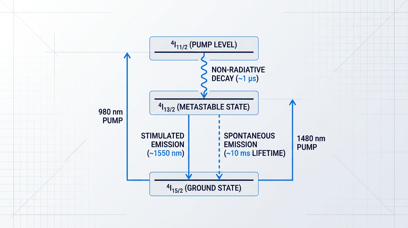
In both cases, population accumulates in the metastable state ⁴I₁₃/₂. This is where the amplification happens: ions sitting in ⁴I₁₃/₂ are available to interact with signal photons near 1550 nm and produce gain through stimulated emission.
The spontaneous emission lifetime of the ⁴I₁₃/₂ level in silica glass is approximately 10 ms — roughly four orders of magnitude longer than the ~1 µs lifetime of the ⁴I₁₁/₂ pump level above it. This disparity is precisely what makes population inversion achievable at moderate pump powers: ions accumulate in ⁴I₁₃/₂ far faster than they decay out of it.
Because the erbium population responds to changes in optical power on a ~10 ms timescale, it cannot follow the sub-nanosecond intensity fluctuations of individual data channels. This means gain saturation induced by one WDM channel cannot modulate the gain experienced by adjacent channels — cross-channel crosstalk via the gain medium is intrinsically suppressed by atomic physics, without any additional system-level mitigation.
Stimulated emission is the amplification mechanism: an incoming signal photon near 1550 nm triggers an excited Er³⁺ ion in the ⁴I₁₃/₂ state to drop to the ground state, releasing a second photon that is coherent with — identical in wavelength, direction, and phase to — the triggering photon.
Spontaneous emission is the competing process: an excited Er³⁺ ion decays without stimulation, emitting a photon in a random direction and with random phase. When these spontaneously emitted photons propagate through the gain medium and are subsequently amplified, the result is amplified spontaneous emission (ASE) — the primary noise source in EDF-based systems, which will be examined in detail later in this guide.
Gain bandwidth and the glass host
In a crystalline host, Er³⁺ would emit at a narrow, well-defined wavelength set by the regular, repeating crystal field. In amorphous silica glass, the local environment surrounding each Er³⁺ ion is slightly different from its neighbours — the disordered glass structure produces site-to-site variations in the local electric field that each ion experiences.
These local field variations produce slightly different Stark splitting of the ⁴I₁₃/₂ and ⁴I₁₅/₂ energy manifolds for each ion — a phenomenon known as inhomogeneous broadening. The ensemble of ions, each with a marginally different transition frequency, produces a broad, smooth gain spectrum rather than a sharp line.
The practical result is a gain bandwidth that spans the C-band (1530–1565 nm) and extends into the L-band (1565–1625 nm) — a spectral window wide enough to carry tens to hundreds of simultaneous WDM channels, each on its own wavelength.
EDF operates entirely in the optical domain: pump light excites the erbium ions, and signal photons are amplified by stimulated emission with no conversion of the signal to electrical form at any point. This all-optical operation is what gives EDF its low noise floor, its transparency to signal bit rate and modulation format, and its natural compatibility with WDM systems where a single amplifier must simultaneously handle many independent channels.
With the physics of the erbium ion established, the next step is understanding how that physics manifests in the engineering parameters that govern amplifier performance — the figures that appear on EDF datasheets and drive real design decisions.
Key EDF Parameters and Their Amplifier Design Implications
An EDF datasheet is deceptively compact: a handful of figures covering absorption, geometry, and loss. But those numbers encode a web of trade-offs that determine whether your amplifier meets its gain, efficiency, and compatibility targets — or falls short in ways that are difficult to diagnose after the fact.
The parameters on a datasheet do not vary independently. Mode field diameter, numerical aperture, and the confinement factor are geometrically coupled. Dopant concentration and absorption coefficient are chemically coupled. Gain efficiency is a composite of all of them. Understanding each parameter individually matters; understanding how they interact is what separates a deliberate fibre specification from an optimistic one.
Dopant Concentration and the Quenching Limit
Erbium dopant concentration sets the number of gain-producing Er³⁺ ions per unit length of fibre, directly controlling both absorption per metre and gain per metre — higher concentration means more signal amplification in a given fibre length.
There is, however, a ceiling. At elevated erbium loadings, ions cluster together and undergo concentration quenching: ion-ion energy transfer (cooperative upconversion) causes excited ions to de-excite non-radiatively before they can contribute to stimulated emission, degrading quantum efficiency and increasing heat deposition.
Aluminium co-doping raises this quenching threshold by dispersing erbium ions more uniformly through the glass matrix, reducing clustering and permitting higher erbium concentrations without the associated efficiency penalty — the mechanism that makes high-concentration EDF designs practical.
Pump Absorption Coefficients
The absorption coefficient at a given pump wavelength, quoted in dB/m, tells you how efficiently the fibre extracts power from the pump over each metre of its length — the primary parameter for calculating optimum fibre length in an amplifier design.
EDF datasheets typically quote two figures: absorption at 980 nm and at 1480 nm, corresponding to the two dominant pump bands used in EDFAs.
A higher absorption coefficient lets a shorter fibre absorb the same total pump power, which is attractive for compact designs. The trade-off is increased sensitivity to pump power variation: with a steeper absorption curve per unit length, small fluctuations in launched pump power translate to proportionally larger changes in population inversion and therefore gain.
Mode Field Diameter, Numerical Aperture, and Confinement
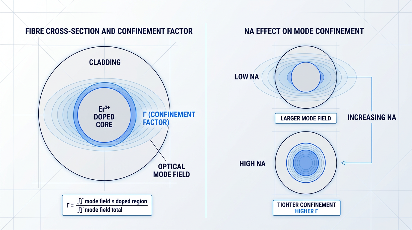
Mode field diameter (MFD) is the effective diameter of the guided optical mode in the fibre core. A smaller MFD concentrates both pump and signal modes into a tighter cross-sectional area, increasing optical intensity at the erbium ions and improving gain efficiency.
EDF is typically designed with a smaller MFD than standard passive transmission fibre. This geometric mismatch at the EDF–SMF splice is a direct design trade-off: the tighter mode confinement that improves gain efficiency is the same property that introduces mode-coupling loss at the interface.
Numerical aperture (NA) governs MFD through the fibre's refractive index contrast — a higher NA confines the optical mode more tightly, reducing MFD. Raising NA therefore simultaneously improves gain efficiency and contributes to splice loss at the EDF–SMF junction, where NA mismatch compounds the MFD mismatch.
The underlying mechanism connecting both MFD and NA to gain is the confinement factor Γ (Gamma): the overlap integral between the spatial distribution of the optical mode and the erbium-doped region of the core. Only the fraction of the mode that physically overlaps with erbium ions drives stimulated emission — Γ is the geometric quantity that determines how much of the guided light actually does useful work.
Maximising Γ requires concentrating the mode within the doped region, which means a small core and high refractive index contrast. Γ is rarely quoted directly on commercial datasheets, but it is the physical mechanism underpinning both MFD and NA — the unifying concept that ties the geometric parameters together.
The cutoff wavelength is the wavelength below which the fibre supports more than one guided mode. For single-mode operation at 1550 nm, the cutoff wavelength must fall below 1550 nm. A secondary consequence arises at 980 nm pump wavelengths: since 980 nm is shorter than the cutoff wavelength of many EDF designs, the fibre may guide multiple pump modes, which affects the uniformity of pump absorption along the fibre length.
Background Loss and Gain Efficiency
Background loss is the passive attenuation at signal and pump wavelengths arising from impurities, scattering centres, and OH absorption — entirely distinct from the erbium absorption and gain spectrum. It sets a floor on achievable net gain: even with complete population inversion, signal photons are continuously lost to background attenuation as they propagate.
Background loss also defines the maximum useful fibre length. Beyond a certain point, accumulated background attenuation outpaces gain, and adding more fibre reduces net output rather than increasing it. This makes background loss a quality-of-manufacture parameter and a meaningful differentiator between fibre grades.
Gain efficiency, expressed in dB/mW, is the practical figure of merit that collapses absorption coefficient, MFD, and Γ into a single number: how many decibels of small-signal gain the fibre delivers per milliwatt of launched pump power. It allows direct comparison between fibre designs without separately evaluating each underlying geometric and chemical parameter.
For low-power and compact amplifier applications, gain efficiency is often the primary selection criterion — a fibre with higher gain efficiency reaches a target gain at lower pump power, relaxing requirements on the pump diode and reducing thermal load.
Γ is almost never listed on a commercial EDF datasheet, yet it is the physical reason MFD and NA matter for gain. A fibre with a smaller MFD and higher NA will show better gain efficiency precisely because Γ is larger — so when two fibres look similar on absorption and concentration, their geometric parameters are what actually differentiates amplifier performance.
These parameters collectively define the design space for erbium doped optical fibers. The next section examines how different fibre architectures — standard single-mode, large mode area, double-clad, and polarisation-maintaining — each navigate that space by making deliberate trade-offs between them.
EDF types and their design trade-offs
With the parameter framework from §4 in hand, the next question is which fibre architecture those parameters describe. Every EDF structural family exists because someone needed to solve a problem that the previous architecture could not — and in solving it, introduced a new set of constraints. Understanding that trade-off map is what separates a deliberate fibre selection from a default one.
Standard single-mode EDF
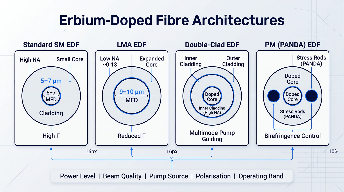
Standard single-mode EDF is the baseline architecture for telecom EDFA and low-to-medium power applications, characterised by a small core, high numerical aperture, and a mode field diameter typically in the 5–7 µm range — geometry that produces a high confinement factor Γ and maximises pump intensity at the erbium ions when driven by a 980 nm or 1480 nm single-mode diode.
The trade-off is baked into the same geometry that makes it efficient: tight mode confinement raises peak signal intensity, which means nonlinear effects such as stimulated Raman scattering become limiting at elevated signal powers, and pump power scaling is capped by what a single-mode diode can deliver.
Large mode area (LMA) EDF
Large mode area EDF addresses the nonlinearity ceiling by expanding the MFD to roughly 9–10 µm and reducing NA to around 0.13, which lowers peak intensity in the core, suppresses stimulated Raman scattering and self-phase modulation, and raises the optical damage threshold — enabling signal powers that standard SM EDF cannot sustain.
The cost is a reduced confinement factor Γ: the larger mode overlaps less efficiently with the erbium-doped region, so gain efficiency falls relative to standard SM EDF, and the lower NA makes the fibre more sensitive to angular misalignment at the splice point, demanding tighter process control during assembly. LMA EDF sits on the power ladder between standard SM and double-clad — the right step up when nonlinearity is the constraint but pump power is not yet the bottleneck.
Double-clad EDF
The structural innovation in double-clad EDF is the inner cladding: a large-area multimode waveguide surrounding the rare-earth-doped core, with a higher NA than the outer cladding, which guides high-power pump light from broad-area diode bars or diode stacks that cannot be coupled into a single-mode core.
The cladding-to-core area ratio governs how efficiently that pump energy is absorbed — a large ratio slows pump absorption and requires longer fibre lengths to extract the available pump power. Inner cladding geometry matters here: non-circular profiles such as D-shaped, offset-core, or octagonal cross-sections break the helical ray trajectories that would otherwise propagate through the cladding without ever crossing the doped core, substantially improving pump absorption efficiency.
Double-clad architecture enables watt-class to hundred-watt-class output from a single-mode or near-single-mode signal port, but it requires multimode pump sources, careful pump coupling design, and longer fibre runs than core-pumped equivalents. If the application demands high power, double-clad is not an upgrade to consider later — it is the correct starting architecture from the first design decision.
Polarisation-maintaining (PM) EDF
Polarisation-maintaining EDF introduces controlled birefringence through stress rods flanking the core (the PANDA configuration) or through an elliptical core geometry, maintaining the linear polarisation state of the propagating signal — a requirement in coherent communications, narrow-linewidth amplifiers, and interferometric sensing systems such as fibre optic gyroscopes, where polarisation cross-coupling directly degrades bias stability.
PM EDF is available in both standard SM and LMA variants, so the polarisation-maintaining property is an additive structural choice rather than a separate fibre family. The costs are real: PM EDF carries a price premium, requires angular alignment of the stress rods or elliptical core at every splice point, and exhibits slightly higher background loss than non-PM equivalents — penalties that are only justified when the downstream system genuinely requires polarisation control.
Er/Yb co-doped double-clad fibre
In Er/Yb co-doped double-clad fibre, ytterbium acts as a sensitiser: Yb³⁺ has a very large absorption cross-section at 976 nm and a broad absorption band, absorbs pump light efficiently across the large cladding area, and transfers the excited-state energy to adjacent Er³⁺ ions via a resonant energy transfer process, populating the metastable ⁴I₁₃/₂ level and producing gain at 1530–1565 nm.
The sensitiser mechanism dramatically improves pump absorption efficiency in double-clad geometries compared to Er-only doping at equivalent concentrations, but the energy transfer is sensitive to dopant concentration ratios and host glass chemistry — incomplete transfer leaves Yb³⁺ acting as a parasitic absorber rather than a pump relay, and some host glass compositions are susceptible to photodarkening under sustained high-power operation. This architecture is used in high-power pulsed and CW amplifiers in the 1530–1565 nm range where efficient absorption from multimode diodes is the primary design driver.
C-band vs L-band optimised fibres
The gain spectrum of Er³⁺ in silica peaks near 1532 nm and extends across the C-band to roughly 1565 nm; gain falls off toward the L-band (1565–1625 nm), where the emission cross-section is lower. C-band optimised fibre is designed for gain efficiency near the emission peak, using moderate erbium concentration and shorter fibre lengths, while L-band optimised fibre requires higher erbium concentration and longer fibre lengths to achieve net gain far from the peak — and exploits lower population inversion levels that tilt the gain spectrum toward longer wavelengths.
C-band and L-band fibres are not interchangeable: specifying the wrong fibre for the target band produces either insufficient gain or runaway ASE, neither of which is recoverable through amplifier design alone once the fibre is chosen.
Whether the application uses a single-mode pump diode (core-pumped) or a multimode diode bar or stack (cladding-pumped) determines which fibre architectures are physically viable before any other parameter is considered. Establishing this first eliminates half the design space immediately.
Taken together, the fibre type families above map onto a set of practical selection axes that the designer should work through in roughly this order:
- Application power level: Output power requirement determines whether standard SM, LMA, or double-clad architecture is needed. High power must be designed in from the start.
- Required beam quality: Single-mode output constrains the signal core to single-mode or near-single-mode, regardless of how large the pump cladding is.
- Pump source type: Single-mode diode means core-pumped SM or LMA. Multimode bar or stack means cladding-pumped double-clad. This axis is often the most constraining.
- Polarisation requirement: Coherent systems, FOG sensors, and polarisation-sensitive downstream components require PM EDF; all others pay an unnecessary cost penalty.
- Operating band: C-band and L-band optimised fibres differ in erbium concentration, fibre length, and inversion regime — select before specifying any other parameter.
- Integration form factor: MFD and NA differences between EDF types and passive SMF drive splice loss at every interface — a mismatch here affects system noise figure.
With the fibre architecture selected, the next design decision moves upstream to the pump: which wavelength to use, and how the host glass chemistry shapes the efficiency and noise figure picture — the subject of §6.
Pump Wavelength Selection and Co-dopant Chemistry
Before a single photon of signal enters your EDF, two upstream decisions have already set the ceiling on noise figure, gain bandwidth, maximum erbium loading, and radiation tolerance: which pump wavelength you drive the fibre with, and what host glass chemistry the fibre was fabricated from. Datasheets rarely surface either choice in full — yet both determine whether your amplifier meets its performance targets or falls short in ways that are difficult to diagnose after the fact.
980 nm vs 1480 nm: What Each Choice Commits You To
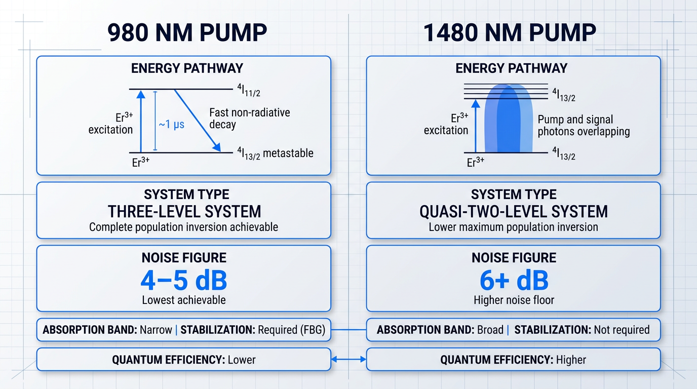
Pumping at 980 nm excites Er³⁺ to the ⁴I₁₁/₂ level, which decays non-radiatively to the metastable ⁴I₁₃/₂ state on a timescale of roughly 1 µs — fast enough that the intermediate level stays essentially depopulated under normal pump conditions.
That rapid intermediate decay is what makes 980 nm pumping a genuine three-level system: with the ⁴I₁₁/₂ level perpetually emptied, near-complete population inversion of the ⁴I₁₃/₂ manifold is achievable, pushing the system toward the 3 dB quantum noise limit.
In practice, 980 nm-pumped EDFAs achieve noise figures in the 4–5 dB range — the lowest attainable with any conventional pump scheme, and the primary reason 980 nm is the standard choice for preamplifier stages where noise figure is the governing constraint.
The engineering cost of 980 nm is its narrow absorption band: pump diodes must be wavelength-stabilised, typically via a fibre Bragg grating, to remain on the absorption peak across operating temperature variations. This adds component cost and supply-chain complexity that should be factored into system-level trade-offs, not treated as a footnote.
1480 nm pumping operates on a fundamentally different mechanism: the pump photons excite Er³⁺ directly into the upper manifold of the ⁴I₁₃/₂ state itself, making it a quasi-two-level system where pump and signal share the same energy manifold.
Because the pump and signal levels overlap, the maximum achievable population inversion is inherently lower than with 980 nm — which translates directly into a higher noise figure floor, typically 6 dB or above in practical booster configurations.
What 1480 nm gains in return is meaningful: the pump photon energy is much closer to the signal photon energy, so less power is dissipated as heat during non-radiative relaxation, yielding higher quantum efficiency in photon conversion. The absorption band around 1480 nm is also substantially broader, so pump diodes do not require wavelength stabilisation — a real cost and reliability advantage in high-power booster stages.
The practical resolution is that 980 nm and 1480 nm are not competing choices — they are complementary tools optimised for different amplifier stages. High-performance EDFA designs routinely combine both: a 980 nm co-propagating pump at the input for minimum noise figure, and a 1480 nm counter-propagating pump at the output stage for maximum saturated output power.
Choosing 980 nm or 1480 nm is not an either/or decision at the system level. The lowest noise figure (4–5 dB) comes from 980 nm at the input stage; the highest output power efficiency comes from 1480 nm at the booster stage. Treating them as mutually exclusive leaves performance on the table.
For high-power booster stages operating in saturation, 1480 nm is the practical default: higher quantum efficiency, no stabilisation requirement, and sufficient output power capacity make it the better fit where noise figure is secondary to raw gain.
Host Glass Chemistry and Co-dopant Trade-offs
If pump wavelength is the operational lever, host glass chemistry is the material foundation that determines what the fibre is capable of in the first place. The host composition controls the erbium emission cross-section profile, the gain bandwidth shape, the concentration quenching threshold discussed in §4, and — critically for space and defence applications — radiation sensitivity.
Aluminium co-doping is the single most consequential host chemistry choice in commercial EDF design. Al disrupts the periodic silica network structure, which reduces the tendency of Er³⁺ ions to cluster and raises the concentration quenching threshold — enabling higher erbium loadings before ion-ion energy transfer begins to degrade performance. It simultaneously broadens and flattens the gain spectrum across the C-band by creating a distribution of local Er³⁺ site symmetries.
Alumino-germanosilicate hosts — combining Al and Ge in a silica matrix — achieve the best combination of gain bandwidth and post-flattening gain flatness, and represent the dominant commercial host chemistry for C-band EDFA fibre.
Germanium co-doping raises the core refractive index, enabling the high numerical aperture values that tighten mode confinement and maximise overlap between the pump field and the erbium-doped region. The trade-off is real: Ge-doped fibres are more susceptible to radiation-induced attenuation than Al-doped equivalents, and erbium concentration is practically limited to below approximately 100 ppm before significant ion clustering degrades gain efficiency.
Phosphorus co-doping raises the core index and can suppress aluminium segregation during preform fabrication. However, phosphorus is a well-documented precursor to radiation-induced structural defects in silica glass — making P-doped fibre a poor choice for any application with elevated radiation exposure. This is a design constraint, not a minor caveat: phosphorus co-doping is generally excluded from space and high-radiation system specifications.
Pure silica core fibre (with fluorine-doped cladding for index contrast) is the most radiation-tolerant host architecture precisely because it avoids the defect-generating co-dopants that drive radiation-induced attenuation. The trade-off is narrower gain bandwidth and lower erbium solubility, which constrains achievable gain per unit length — a worthwhile exchange for space applications where radiation hardness is the primary constraint.
The radiation sensitivity hierarchy across host chemistries runs from pure silica core (most tolerant) through Al-doped and Ge-doped to P-doped (least tolerant) — a ranking with direct implications for fibre qualification in space, defence, and nuclear environments, which §10 addresses in full.
None of this chemistry is typically disclosed on commercial datasheets. Absorption coefficient, background loss, and cut-off wavelength appear; host composition rarely does — yet it is the hidden variable that governs gain flatness, maximum erbium concentration, and radiation performance simultaneously.
Engineers qualifying erbium doped optical fibers for demanding applications should treat host chemistry as a first-order specification axis to probe directly with the supplier. Ask explicitly: what co-dopants are present, and in what concentration ranges — do not infer the answer from headline datasheet figures.
Aluminium co-doping broadens the gain spectrum appreciably, but even the flattest Al-doped host still exhibits inherent gain non-uniformity across the C and L bands. That residual non-uniformity — the gain peak near 1532 nm, the semi-flat plateau, and the roll-off toward longer wavelengths — is a direct consequence of the Er³⁺ emission cross-section, and managing it is the subject of the next section.
Gain Bandwidth, Flatness, and Managing the C and L Bands
The gain spectrum of an erbium-doped fibre amplifier is not flat — and in a multi-channel WDM system, that non-uniformity is not a minor inconvenience but a fundamental engineering problem that compounds with every amplifier stage in the link.
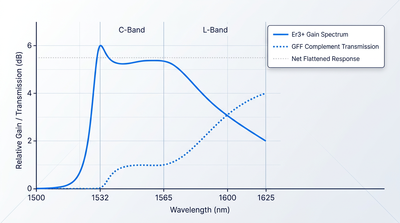
The root cause is the Stark splitting of the ⁴I₁₃/₂→⁴I₁₅/₂ transition in an amorphous silica host, as established in §3. The disordered glass environment distributes Er³⁺ ions across a range of local field environments, producing a characteristic gain profile: a pronounced peak near 1532 nm, a semi-flat region extending to approximately 1565 nm that defines the C-band, and a long tail extending further into the L-band.
Untreated, this profile can produce gain variations of several dB across the C-band alone. In a single amplifier that is manageable; across a cascade of amplifiers in a long-haul link, the variation compounds stage by stage, with channels near the 1532 nm peak accumulating progressively more power while edge channels fall further behind.
The UCSB ECE228 lecture notes on EDFA gain (Blumenthal) state the practical engineering tolerance directly: gain tilt must be held to better than 1 dB per amplifier if stages are to be cascaded without channel power divergence across the WDM link.
The gain spectrum is not a fixed property of the fibre — it shifts with population inversion level. Higher inversion (strong pump, light signal load) tilts gain toward shorter C-band wavelengths. Lower inversion shifts the balance toward longer wavelengths, enabling L-band gain. Operating conditions are therefore as important as fibre choice when managing gain tilt.
The population inversion level, set by the balance of pump power and signal load as discussed in §6, is the dynamic control variable for gain shape. This is why L-band amplification is achievable at all from the same Er³⁺ transition — and it is why gain-flattening strategies must account for operating conditions, not just fibre properties.
The primary external mitigation is the gain-flattening filter (GFF): a passive or active optical element whose transmission profile is shaped to be the spectral complement of the EDFA gain curve, so that the combined response across the signal band is flat.
- Long-period fibre gratings: Periodic refractive index modulations along the fibre couple light from the guided core mode to lossy cladding modes at specific wavelengths, creating a controlled attenuation notch.
- Thin-film interference filters: Multi-layer dielectric coatings produce a wavelength-selective transmission profile; robust and temperature-stable, making them well-suited to deployed systems.
- Fibre loop mirrors: Sagnac-based all-fibre interferometers that exploit wavelength-dependent coupling to produce a spectrally shaped reflection or transmission response.
Research published in Optics Communications (Varshney et al., 2007) demonstrated that a side-polished fibre GFF can flatten EDFA gain to within ±0.7 dB over a 30 nm bandwidth in the C-band — a result independently corroborated by Kim et al. in IEEE Photonics Technology Letters, who achieved gain flatness below 0.7 dB over a span exceeding 35 nm using an all-fibre acousto-optic tunable filter.
The trade-off is real: every GFF introduces insertion loss that adds directly to the noise figure budget, and a GFF designed for one inversion level will leave residual gain tilt if operating conditions shift — making dynamic or adjustable filter designs valuable in systems where pump power or signal load varies.
The burden on external GFFs can be reduced by choosing EDF with a flatter native gain profile from the outset. Specialised refractive index profiles — including staircase profiles and depressed inner cladding designs discussed in §4 — and selective erbium doping geometries such as ring-doping rather than uniform core doping can reduce native gain tilt before any filter is applied.
The aluminium co-doping strategy covered in §6 is directly relevant here: Al³⁺ broadens the gain spectrum by distributing Er³⁺ ions across a wider range of crystal field environments, reducing the sharpness of the 1532 nm peak and producing a more uniform gain profile across the C-band.
L-Band Amplification: A Distinct Design Challenge
The L-band (1565–1625 nm) sits far from the Er³⁺ emission peak, where gain at normal inversion levels is low. Achieving useful amplification across the L-band requires operating the EDF at lower inversion — which in practice means longer fibre lengths and carefully managed pump power.
As noted in §5, L-band optimised EDF fibres are specifically designed for these longer operating lengths, with doping profiles and refractive index geometries chosen to maintain efficiency across the extended fibre span that lower inversion demands.
The consequences of lower inversion are two-fold: accumulated amplified spontaneous emission (ASE) increases with fibre length, and the noise figure rises as the inversion level falls. Both are manageable — but they require architectural choices that a C-band-only design does not.
Two-stage cascaded configurations and double-pass architectures are the most common mitigations. A two-stage design allows an optical isolator and mid-stage attenuator or filter to be inserted between stages, suppressing backward-propagating ASE before it is re-amplified. A double-pass arrangement routes the signal through the gain medium twice, achieving higher gain per unit length of EDF at the cost of additional design complexity.
For systems requiring simultaneous C+L dual-band coverage, the conventional approach is to split the signal bands before amplification, route each through a dedicated EDFA (C-band and L-band stages in parallel), and recombine the amplified bands at the output.
The alternative — a single gain stage capable of amplifying both bands simultaneously — is an active area of system design, where fibre type, doping profile, length, and pump architecture must all be optimised together to sustain adequate inversion across the full C+L spectral range without sacrificing noise performance in either band.
The noise figure implications of L-band operation, and the ASE dynamics that drive them, are worth examining in quantitative detail — and that is precisely where the next section picks up.
EDFAs Engineered for Your Gain Requirements
Gain flatness and noise figure targets don't resolve themselves on paper. See how our custom EDFAs are specified to meet real WDM deployment constraints.

ASE, Noise Figure, and Splice Loss: Engineering Pain Points
The fibre parameters covered earlier — erbium concentration, mode field diameter, numerical aperture, fibre length — do not exist in isolation. When you connect EDF into a real amplifier chain, those same parameters drive two failure modes that account for the majority of EDFA integration headaches: amplified spontaneous emission building up to degrade system OSNR, and splice loss at every EDF–SMF junction accumulating into a meaningful power budget penalty.
ASE and Noise Figure in EDFAs
Every spontaneously emitted photon that falls within the gain bandwidth of the erbium medium gets amplified as it travels through the fibre, exactly as a signal photon would — this is amplified spontaneous emission, and it is always present regardless of how well the amplifier is designed.
Noise figure quantifies the damage: it is the ratio of input optical SNR to output optical SNR, expressed in dB, and it sets a hard ceiling on the OSNR budget available to downstream receivers.
Quantum mechanics imposes a fundamental floor of 3 dB — even a theoretically perfect amplifier with complete population inversion must add at least half a photon of noise per mode per unit gain. Well-designed EDFAs pumped at 980 nm approach this limit, typically achieving noise figures of 4–6 dB in practice; L-band amplifiers, as established in the gain bandwidth discussion, carry a further penalty of 6–7 dB or more due to the lower inversion efficiency at longer wavelengths.
Fibre length and erbium concentration interact directly with ASE build-up: longer fibres and higher dopant concentrations increase the total gain length, which amplifies more spontaneous emission along with the signal. The most damaging scenario is an under-pumped section at the far end of the gain fibre — a region where pump power has been exhausted but erbium ions remain, acting as a pure ASE source with no net signal gain contribution.
The architectural response is well-established: optical isolators prevent back-reflected ASE from re-entering the gain medium and seeding parasitic oscillation, while a two-stage amplifier design splits the gain budget so the first stage runs at high inversion with 980 nm pumping for minimum noise figure, and the second stage handles output power — the same architecture introduced in the gain bandwidth section for flatness management now does double duty as a noise management tool.
Physics prevents any optical amplifier from achieving a noise figure below 3 dB. The practical gap — 4 to 6 dB with optimised 980 nm pumping — represents real engineering headroom. Every tenth of a dB saved in the first stage propagates as improved OSNR through every subsequent span in the link.
Controlling ASE ultimately comes down to matching fibre length and pump power profile so that no section of EDF sits below the inversion threshold — a constraint that feeds directly into how the fibre's physical geometry and dopant uniformity are specified.
Splice Loss at the EDF–SMF Interface
EDF is typically manufactured with a core mode field diameter of roughly 5–7 µm and a correspondingly high numerical aperture — necessary for tight pump-signal overlap and efficient gain. Standard SMF-28 has an MFD of approximately 10.4 µm. That size mismatch means the optical mode cannot couple cleanly across the splice: the Gaussian beam overlap integral between the two mode profiles yields a transmission loss that scales with the square of the MFD ratio, even when the physical splice itself is geometrically perfect.
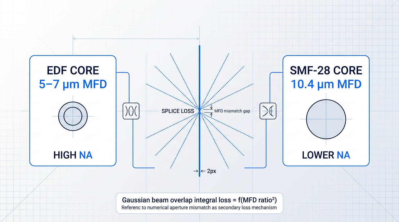
Numerical aperture mismatch compounds the MFD problem: light propagating at angles that exceed the acceptance cone of the receiving fibre is simply lost at the interface. Both effects share the same root cause — EDF is engineered for high gain efficiency through tight mode confinement, and that confinement is inherently incompatible with the larger, lower-NA geometry of SMF-28.
In a multi-stage amplifier with several EDF–SMF junctions, even modest per-splice loss accumulates into a budget item that cannot be ignored; and measurement itself becomes unreliable without care, because heterogeneous splices produce artefacts in unidirectional OTDR traces — apparent gainers (negative-loss events) in one direction and exaggerated losses in the other, depending on which fibre the OTDR launches from.
The correct measurement approach is bidirectional OTDR characterisation: take a trace from each end and average the two loss values, which cancels the directional artefact and yields the true splice loss. Relying on a single-direction trace at an EDF–SMF junction will give a misleading result in either direction.
- Thermal Expanded Core (TEC): Controlled localised heating expands the EDF core toward SMF-28 dimensions before splicing, directly reducing MFD mismatch at the joint. Preferred when fusion splicer and heat source are available.
- Bridging Fibre: An intermediate fibre with MFD between EDF and SMF-28 splits the mismatch across two lower-loss splices, often yielding lower total loss than one large-mismatch joint.
- Splice-Compatible EDF: Fibre variants engineered with larger MFD and lower NA for better SMF-28 compatibility — a design-stage trade-off that sacrifices some gain efficiency to avoid the problem entirely.
In practice, the choice follows a straightforward priority order: use the thermal expanded core technique when the equipment is available, since it achieves the best loss reduction without introducing extra components; fall back to a bridging fibre when TEC tooling is not accessible; and specify a splice-compatible EDF variant only when the gain efficiency penalty is acceptable at the design stage — it is the one mitigation that cannot be applied after the fibre has been chosen.
Both the ASE behaviour and the splice compatibility of an erbium doped optical fiber are ultimately determined upstream of the installation bench, by the manufacturing process that sets the dopant concentration profile, core geometry, and refractive index distribution — which is where the next section picks up.
EDF Manufacturing and Doping Processes
An EDF datasheet tells you what a fibre does — its absorption at 980 nm, its mode field diameter, its background loss. It does not tell you how those numbers were produced, or how reliably they will be reproduced on the next batch. For engineers specifying fibre for demanding applications, that omission matters more than most datasheets suggest.
MCVD with Solution Doping
Modified chemical vapour deposition (MCVD) combined with solution doping is, as one widely cited review of the field describes it, "the most prevalent" commercial route for producing rare-earth-doped fibres, valued for its simplicity and adaptability.
The process begins with the deposition of a porous silica soot layer inside a silica substrate tube at an appropriate deposition temperature; the porous layer then acts as a sponge during the subsequent impregnation step.
Impregnation is carried out by soaking the porous deposit in a solution of rare-earth and co-dopant salts — typically ErCl₃ and AlCl₃ dissolved in an ethanolic solvent — for a controlled dipping period.
After soaking, the solvent is removed, the layer is oxidised and dehydrated in the presence of chlorine to eliminate absorbed hydroxyl, then sintered at elevated temperature to consolidate the doped glass; the tube is finally collapsed into a solid preform from which fibre is drawn.
The practical problem with solution doping lies in the sensitivity of dopant incorporation to multiple process variables simultaneously: soot porosity, pore size distribution, solution concentration, dipping time, and drying conditions all interact.
Research into porous layer morphology has shown that even deposition temperature alone significantly affects pore size and uniformity — lower deposition temperatures produce smaller, more uniform pores, while higher temperatures cause partial pore collapse and a broader size distribution, both of which translate directly into non-uniform dopant uptake along the preform length.
The consequence for the system designer is longitudinal non-uniformity: absorption coefficient, gain per unit length, and background loss can vary along a spool, and between spools from different production runs.
One technique investigated to address this is dual-layer soot deposition: applying two soot layers at optimised temperatures rather than a single layer. Published work on this approach reports improved longitudinal uniformity of the core refractive index profile alongside increased dopant incorporation compared to single-layer deposition.
Vapour-Phase Doping and Radial Profile Control
The alternative to post-deposition impregnation is vapour-phase chelate delivery (VPCD), where rare-earth chelate compounds — typically metal organic species such as Er(thd)₃ or Yb(thd)₃ — are sublimated and transported to the reaction zone via a carrier gas, where they co-deposit with silica and alumina during core layer formation.
Because deposition is continuous rather than a discrete soak-and-dry cycle, the dopant profile along the preform length is directly governed by gas-phase composition and flow parameters, which can be held constant across the full deposition run — yielding tighter longitudinal uniformity than solution doping typically achieves.
The more significant engineering capability of vapour-phase techniques, however, is radial profile control: by adjusting deposition conditions layer by layer, fabricators can engineer the dopant distribution across the fibre cross-section to produce uniform, centralised, or circumferential geometries rather than the roughly uniform radial profile that solution doping delivers.
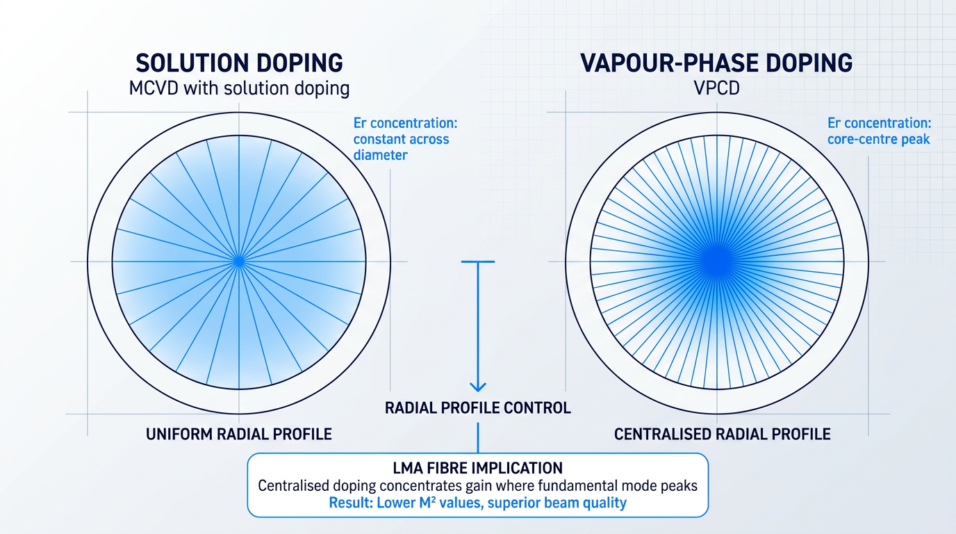
In large mode area (LMA) fibres, this profile control has a direct bearing on beam quality: a centralised doping geometry concentrates gain in the core centre, where the fundamental mode has its highest intensity.
Higher-order modes, which have a broader spatial extent than the fundamental, overlap less with the centralised doped region and therefore experience lower gain — published experimental work confirms that LMA fibres with centralised doping exhibit lower M² values than equivalent fibres with uniform or circumferential doping profiles, without requiring aggressive coiling or other mechanical mode-filtering approaches.
The trade-off is process complexity: vapour-phase doping requires careful control of sublimation temperatures, carrier gas flow rates, and transport line temperatures to prevent precursor condensation before the reaction zone, and it is not as widely deployed commercially as solution doping.
For space, defence, and high-reliability sensing applications, batch-to-batch consistency in absorption coefficient, mode field diameter, and background loss is as important as peak nominal performance. A fibre that meets its datasheet spec on one batch but drifts on the next creates re-qualification burdens and, in the worst case, field failures. The fabrication process behind the numbers is a legitimate and important question to raise with any EDF supplier — solution doping's sensitivity to multiple interacting process variables makes it a particularly relevant one.
The connection between fabrication process and radiation performance runs through exactly the same dopant and impurity profile that governs uniformity: the co-dopants and residual impurities introduced during fabrication directly determine radiation-induced attenuation (RIA) susceptibility.
It is well established that aluminium co-doping — introduced during fabrication to improve erbium solubility and spectral properties — generates Al-related defects under irradiation that produce high RIA at both pump and signal wavelengths; phosphorus, which can enter the glass matrix during certain fabrication routes, is particularly problematic in radiation environments.
Pure-silica-core fibre architectures, which require different fabrication approaches such as fluorine-doped depressed cladding, are the most radiation-tolerant configurations — but this architecture involves its own process constraints and trade-offs that are worth understanding before specifying for space or defence applications.
The fabrication choices that determine dopant uniformity also determine which co-dopants and impurities end up in the glass matrix — and in radiation environments, that distinction becomes a primary design variable, which is where the next section picks up.
Radiation-Hardened EDF and Sensing Applications
The 1550 nm window is not just a telecom convenience — it has become the convergence point for demanding photonics far beyond fibre communications, uniting space-borne amplifiers, airborne LiDAR, free-space optical links, and precision inertial sensing under a single wavelength rationale grounded in physics.
Radiation-Hardened EDF for Space Applications
When ionising radiation passes through a silica fibre, it creates colour centres: point defects in the glass matrix that absorb light at both pump and signal wavelengths, increasing propagation loss and reducing population inversion in the erbium ions.
The pump wavelength typically suffers greater radiation-induced attenuation (RIA) than the signal wavelength, compounding the gain loss: the active medium is starved of pump photons precisely when it needs them most.
RIA severity is strongly governed by host glass composition — a point that connects directly to the co-dopant choices discussed earlier in this guide.
Aluminium co-doping, while beneficial for gain flatness and concentration quenching threshold in telecom applications, significantly increases radiation sensitivity; greater aluminium content in the core correlates directly with higher radiation-induced loss in erbium-doped fibre.
Germanium, used to raise the core refractive index, also increases radiation sensitivity — Ge-doped fibres exhibit substantially higher RIA than pure silica core equivalents under equivalent dose conditions.
Phosphorus is considered unacceptable for space-grade EDF: it is well-documented as a precursor of radiation-induced structural defects and is explicitly excluded from space flight fibre specifications.
The practical consequence is a direct trade-off: the co-dopants that deliver the best telecom EDFA performance are often the most damaging choices for a space amplifier.
Pure silica core fibres — with fluorine-doped depressed cladding to achieve waveguiding without raising the core index — represent the most radiation-tolerant architecture for high total dose environments, and are the standard approach for space-grade passive PM fibre at 1550 nm.
For active erbium-doped fibres, where some glass modifier is needed to achieve adequate Er³⁺ solubility, the challenge is more nuanced and several mitigation strategies are under active development.
Research into Al₂O₃:Er³⁺ nanoparticle-doped fibres has shown that incorporating erbium within alumina nanoparticles — rather than dissolving it homogeneously into the silica matrix — can reduce RIA while preserving spectroscopic performance, as the nanoparticle host partially isolates the erbium environment from the silica defect network.
Cerium co-doping, combined with optimised germanium concentrations, has been demonstrated to limit signal gain degradation to approximately 5 dB after 100 krad (1000 Gy) exposure at 315 mW pump power in a MOPA configuration — a result unachievable in aluminium-heavy telecom-grade fibre under equivalent conditions.
Hydrogen and deuterium loading — which passivates dangling bonds in the silica network — is a known technique for improving radiation tolerance, though it remains an active area of development rather than a universally qualified catalogue option.
The manufacturing provenance covered in the previous section is directly relevant here: the co-dopant profile and its uniformity across the fibre length are set by the deposition process, and batch-to-batch reproducibility of radiation performance is a qualification concern that datasheets rarely fully address.
For flight programme specification, the most actionable metric is gain degradation rather than raw attenuation increase: a figure such as less than 0.25 dB per 100 krad for a 30 dB gain EDFA gives a system engineer something concrete to budget against in a link margin calculation.
When qualifying space EDF, engineers should request radiation-induced gain variation (RIGV) data measured under representative amplifier operating conditions — not just passive RIA on unexcited fibre — and should ask for lot-specific test data rather than catalogue-level typical values, since fibre-to-fibre variation in radiation sensitivity can be significant.
EDF in Sensing: LiDAR, FOG, FSOC, and Beyond
The same 1550 nm window that dominates telecom amplification has driven EDF adoption across a wide range of sensing and ranging applications — and the engineering rationale is more fundamental than wavelength familiarity.
Above approximately 1400 nm, the cornea and lens absorb strongly, preventing laser radiation from reaching the retina; this raises the eye-damage threshold at 1550 nm to levels many orders of magnitude higher than at 1064 nm or 532 nm, enabling outdoor and airborne systems to operate legally at power levels that would be entirely impermissible at shorter wavelengths.
This is not a marginal regulatory advantage: it determines what is physically possible in an uncontrolled-access environment, and it is the primary engineering rationale driving convergence on 1550 nm for outdoor LiDAR, FSOC, and any application where beam safety is a real operational constraint.
Layered on top of the safety argument is the infrastructure advantage: components, connectors, test equipment, and qualified optical fibres developed for the telecom C and L bands are directly available at 1550 nm, substantially reducing development risk compared to building equivalent systems at 1064 nm.
In LiDAR systems, EDF-based MOPA (master oscillator power amplifier) architectures are the standard approach for producing high-power, eye-safe pulses for time-of-flight ranging.
NASA has demonstrated erbium-doped fibre MOPA transmitters for atmospheric CO₂ remote sensing at 1572 nm, achieving pulse energies above 450 µJ at 10 kHz repetition rate, with the MOPA architecture providing both the narrow linewidth needed for differential absorption and the pulse energy needed for long-range operation.
The fibre selection criteria for LiDAR EDF differ substantially from telecom EDFA priorities: peak power handling, ASE suppression (to maintain pulse contrast and ranging accuracy), and compatibility with narrow linewidth seed sources for coherent and Doppler variants are the dominant concerns — not the gain efficiency and noise figure that drive telecom EDF specification.
The fibre optic gyroscope (FOG) represents an entirely different use case: EDF is used not as a gain medium but as a broadband ASE source at 1550 nm, providing the optical input to a Sagnac interferometer.
In a FOG, scale factor accuracy is directly proportional to source mean wavelength, so mean wavelength stability at the parts-per-million level is the critical parameter — not gain or noise figure.
Mean wavelength is sensitive to EDF temperature, pump power fluctuations, and polarisation state, which is why PM EDF is essential for high-grade FOG sources: polarisation mixing in the source fibre directly degrades mean wavelength stability and therefore gyroscope accuracy.
Superfluorescent fibre sources using high-performance EDF have demonstrated mean wavelength stability of 2–3 ppm/°C over operating temperature ranges of −40 to +60°C — a performance level that requires simultaneous control of fibre composition, pump power, and polarisation state.
In free-space optical communications (FSOC), EDF amplification serves ground-station uplink and beacon functions, where the eye-safe wavelength and low atmospheric scattering loss at 1550 nm are both operationally important; NASA's TBIRD demonstration used an EDFA outputting 800 mW at 1550 nm to support a 200 Gbps downlink from low Earth orbit.
In distributed acoustic sensing (DAS) and structural fibre sensing, EDF amplification extends sensing range beyond what passive fibre loss budgets permit, with demonstrated ranges above 200 km using combined erbium and Raman amplification in repeaterless configurations.
Eye safety, atmospheric transmission, and a mature telecom component ecosystem converge at 1550 nm — making erbium-doped fibre the natural platform for LiDAR, FSOC, FOG, and space applications alike. The wavelength was not chosen for these applications; the applications migrated to it because the physics demanded it.
For engineers who have worked through the full arc of EDF specification — from energy-level physics and fibre parameters through gain flatness, noise, manufacturing provenance, radiation hardening, and sensing — the logical next step is translating fibre knowledge into a complete amplifier system.
This is where the distinction between a fibre supplier and a system manufacturer becomes consequential: a well-specified EDF is necessary but not sufficient for a LiDAR transmitter, an FSOC uplink amplifier, or a defence-grade high-power source.
Woodrow Scientific Limited's Custom EDFA is designed precisely for this transition point — engineered end-to-end to the application rather than selected from a fixed catalogue, with every parameter configurable: operating band (C-band, L-band, or dual C+L through a single cable), output power, pulse regime, pulse energy and peak power, cooling, delivery cable, form factor, and control firmware.
The power scalability is directly relevant to the high-power sensing and LiDAR applications covered in this section: pulse energies above 10 mJ, peak powers above 100 kW, and average powers above 100 W represent the leading commercially available levels for erbium fibre, with both C and L bands delivered from a single source through one cable.
Woodrow Scientific, founded in 2012 and manufacturing entirely in Southampton, UK, designs, builds, qualifies, and supports its amplifiers in-house on patented technology — with engineering expertise rooted in Southampton's Optoelectronics Research Centre, the birthplace of the EDFA. In a market where many suppliers are resellers or importers rather than true manufacturers, that in-house depth means direct engineering support throughout integration, genuine ability to adapt the design to application-specific constraints, and a single accountable source for demanding LiDAR, FSOC, sensing, and defence programmes.
EDFA Technology Built for Free-Space Optical Links
Space, airborne, and FSOC applications demand amplifiers that perform under conditions standard telecom EDFAs were never designed for. See how our EDFA technology addresses those requirements.

Conclusion
Specifying EDF: a practical framework for system designers
The central lesson of erbium-doped fibre specification is that precision beats convenience: the right fibre is the one matched deliberately to your system's gain targets, noise budget, host chemistry constraints, and operating environment — not simply the one most readily available.
Get that foundation right, and the decisions that follow — pump selection, coupler geometry, gain-flattening approach, multi-stage architecture — fall into place with far greater clarity.
Frequently asked questions about erbium doped optical fibres
Concise answers to the specification and design questions engineers most commonly carry after working through the guide.
C-band EDF is optimised for gain across 1530–1565 nm, near the Er³⁺ emission peak. L-band EDF operates in the 1565–1625 nm region, where the gain cross-section is lower — so longer fibre lengths and typically higher erbium concentrations are required to accumulate useful gain in the tail of the emission spectrum. For most telecom, LiDAR, and sensing applications centred near 1550 nm, C-band EDF is the default choice. L-band EDF is warranted only when the application specifically requires the 1565–1625 nm window, such as extended WDM channel plans or certain coherent transmission systems. One practical consideration worth noting: L-band amplifiers operate at lower population inversion levels than C-band, which generally results in higher noise figures. If noise figure is a tight constraint, this is a meaningful factor in the decision.
Higher erbium concentration increases gain per unit length, enabling shorter fibre designs. However, above a threshold, concentration quenching sets in: adjacent Er³⁺ ions interact via dipole-dipole coupling, causing excitation to decay non-radiatively rather than contributing to stimulated emission. This reduces population inversion efficiency and degrades gain. The standard engineering response is aluminium co-doping. Al disperses erbium ions more uniformly in the silica matrix, raising the quenching threshold and permitting higher erbium loadings without the associated gain penalty. The practical implication: the optimum erbium concentration is not the maximum achievable. It is the concentration that maximises gain efficiency for a given fibre length and pump power, balanced against quenching onset and any increase in background loss at higher dopant loadings.
The primary cause is mode field diameter (MFD) mismatch. EDF typically has an MFD of 5–7 µm with a higher numerical aperture, compared to SMF-28's ~10.4 µm MFD and NA of ~0.14. Even modest MFD differences produce measurable splice loss, which can be estimated from the standard Gaussian overlap integral. A secondary contribution comes from NA mismatch: when the receiving fibre has a smaller NA than the transmitting fibre, light outside the acceptance cone is lost. Two mitigation approaches are commonly used. The thermal expanded core (TEC) technique applies controlled localised heating to the EDF end, causing the core to expand diffusively toward SMF-28 dimensions before the splice is made. Alternatively, a bridging fibre with intermediate MFD and NA splits the mismatch across two lower-loss splices rather than one large-mismatch joint. One measurement note: heterogeneous EDF–SMF splices produce apparent gainers or exaggerated losses in unidirectional OTDR traces — bidirectional averaging is required for accurate splice loss characterisation.
980 nm pumping achieves near-complete population inversion of the Er³⁺ metastable state, minimising the spontaneous emission component and yielding the lowest achievable noise figures. Practical EDFAs pumped at 980 nm routinely achieve 4–5 dB NF, approaching the 3 dB quantum limit. The mechanism: 980 nm excites Er³⁺ to the ⁴I₁₁/₂ level, which decays rapidly (~1 µs) into the metastable ⁴I₁₃/₂ state. This three-level pathway supports a higher degree of inversion than is achievable via 1480 nm pumping. At 1480 nm, the pump drives Er³⁺ directly into the upper manifold of ⁴I₁₃/₂ — a quasi-two-level process that caps the maximum inversion and typically yields noise figures of 6–7 dB or more. The trade-off is that 980 nm has a narrow absorption band, requiring wavelength-stabilised pump diodes. The broader absorption of 1480 nm is more tolerant of pump wavelength drift, making it the preferred choice for high-power booster stages where noise figure is not the primary constraint.
ASE is noise light generated when spontaneously emitted photons at signal wavelengths propagate through the erbium gain medium and are amplified along with the signal. Unlike stimulated emission, spontaneous emission is random in phase and direction — but photons travelling in the signal direction experience the same gain the signal does, producing a broadband noise floor that accumulates through the fibre. ASE is the primary noise source in EDFAs. In cascaded amplifier chains, it accumulates span by span, degrading the optical signal-to-noise ratio (OSNR). In WDM systems, this OSNR degradation ultimately limits the number of amplifier spans and the achievable data rate. The noise figure of an EDFA directly quantifies the ASE contribution: a lower NF means less ASE power added relative to the signal gain. Practically, minimising ASE requires keeping fibre length well-matched to pump power (avoiding under-pumped sections that generate ASE without contributing useful gain), placing optical isolators to block backward-propagating ASE from re-entering the gain stage, and using multi-stage designs that isolate the low-NF preamplifier stage from the higher-power booster.
EDF amplifies at 1550 nm entirely in the optical domain, with no optical-to-electrical conversion, making it compact and well-suited to the high-sensitivity, eye-safe requirements of space optical communications and sensing. The core challenge in space is radiation-induced attenuation (RIA): ionising radiation creates colour centres in the glass matrix that increase absorption at both pump and signal wavelengths, reducing available gain. Co-dopant choice strongly influences radiation sensitivity. Aluminium significantly increases RIA susceptibility; germanium also raises it; phosphorus is generally considered unacceptable for space-grade fibre. Pure silica core architectures with fluorine-doped cladding offer the best baseline radiation tolerance. Several hardening strategies have been demonstrated: Al₂O₃:Er³⁺ nanoparticle doping reduces RIA while preserving spectroscopic performance; cerium and certain nanoparticle co-doping approaches have shown reduced gain degradation after heavy radiation doses; hydrogen or deuterium loading passivates dangling bonds that would otherwise form colour centres. For space qualification, gain degradation figures under a defined radiation dose are more useful than raw attenuation specs. Batch consistency and qualification heritage carry significant weight alongside peak performance metrics.
Double-clad EDF has a rare-earth-doped single-mode core surrounded by a larger, higher-NA inner cladding. This inner cladding functions as a multimode waveguide, guiding high-power pump light from low-cost multimode diode bars into the fibre — pump light that cannot be coupled efficiently into a single-mode core directly. The key advantage is power scaling. Core-pumped designs are constrained by the brightness and output power of single-mode pump diodes. Cladding pumping decouples the pump coupling problem from the signal guidance requirement: the inner cladding accepts pump light from much higher-power multimode sources, enabling average output powers well beyond what core-pumped architectures can reach. The inherent trade-off is reduced pump absorption per unit length. Because pump light is distributed across the larger cladding cross-section rather than confined to the small doped core, a longer fibre or higher pump power is needed to achieve full inversion. Er/Yb co-doped double-clad fibre addresses this partly by using ytterbium as a sensitiser: Yb³⁺ absorbs pump light at 976 nm very efficiently and transfers the excitation to Er³⁺, improving effective pump absorption in the cladding-pumped geometry.
Approximately 10 ms. This is the radiative lifetime of the metastable ⁴I₁₃/₂ state in a silica glass host — the time constant governing how long an excited Er³⁺ ion remains in the upper laser level before emitting spontaneously. The ~10 ms lifetime matters for two distinct reasons. First, population inversion efficiency: the lifetime is long relative to the pump absorption timescale, so inversion can be established and maintained with milliwatt-level CW pump diodes. A significantly shorter lifetime would demand proportionally higher pump powers to sustain the same inversion level. Second, WDM channel isolation: signal channels in WDM systems modulate at GHz rates, but the ~10 ms lifetime is many orders of magnitude longer than any practical bit period. The erbium population therefore cannot respond to individual signal fluctuations — it integrates over the average total signal power. This suppresses cross-gain modulation between WDM channels, which would otherwise cause one channel's data pattern to corrupt adjacent channels. The actual lifetime varies slightly with host glass composition and co-dopant chemistry, but ~10 ms is the canonical value for alumino-germanosilicate hosts.