

Introduction
This guide is written for engineers, system designers, and technical buyers who need more than a surface-level overview of erbium-doped fibre amplifier technology — people who need to specify, evaluate, or deploy it.
EDFA technology underpins virtually every long-haul fibre network carrying global telecommunications traffic today, yet rigorous, application-oriented resources on the subject remain surprisingly hard to find.
What follows moves through the subject in dependency order: from the atomic physics that make optical gain possible, through component design and pumping configurations, to noise behaviour, gain flatness, and real-world deployment.
By the end, you will have enough understanding of the full stack to make informed engineering decisions with confidence — not just familiarity with the concepts, but a working grasp of what drives performance in practice.
TL;DR
EDFA technology is mature at the physics level — but deploying it correctly is a genuine system-level engineering challenge. Noise figure, gain flatness, and OSNR are not independent parameters you tune in isolation; they are coupled across the full stack from erbium ion behaviour to pumping configuration to WDM channel management. Engineers who understand that coupling make better specification decisions.
This article covers:

Erbium doping physics and optical gain
Pump laser mechanics and core EDFA component design
Forward, backward, and bidirectional pumping trade-offs
ASE noise, noise figure, and OSNR
Gain flatness challenges in WDM and DWDM systems
EDFA deployment contexts and technology limits
What is a Fiber Optic Sensor Amplifier?
The term "fiber optic sensor amplifier" is used in two distinct contexts: industrial photoelectric sensor amplifier units used in factory automation, and — the subject of this guide — the erbium-doped fibre amplifier, or EDFA, a device that amplifies optical signals within a fibre optic communications network entirely within the optical domain.
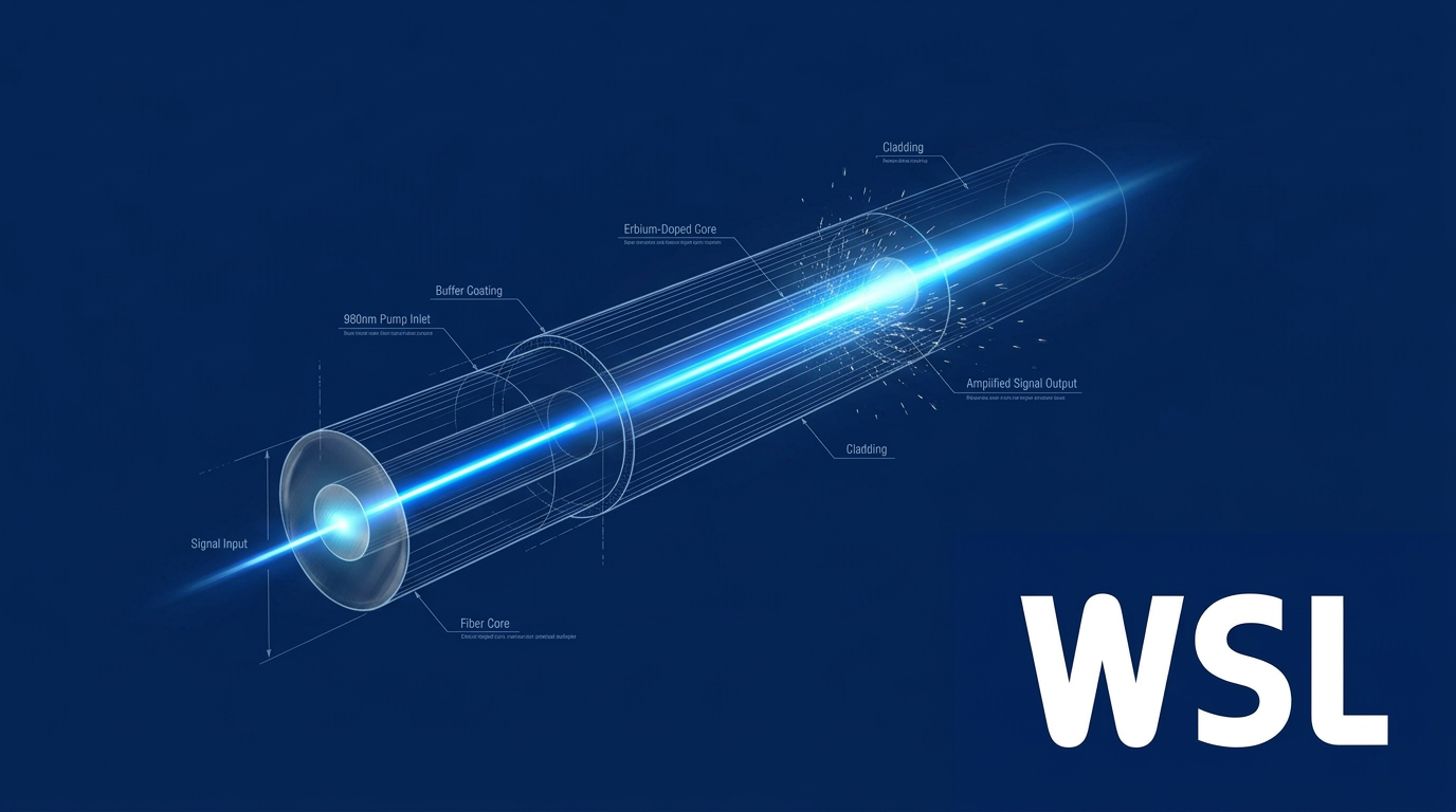
An EDFA is a short length of silica optical fibre whose core has been doped with trivalent erbium ions (Er³⁺), enabling it to amplify light signals in the 1530–1565 nm C-band without converting them to electrical form — the fundamental distinction from electronic repeaters, which require optical-to-electrical-to-optical (OEO) conversion at every amplification stage.
The amplification mechanism works as follows: a pump laser injects energy into the erbium-doped fibre, exciting Er³⁺ ions into a metastable energy state — a condition known as population inversion. When a signal photon at the correct wavelength passes through, it triggers those excited ions to release a coherent photon at the same wavelength, direction, and phase, a process called stimulated emission, producing optical gain.
EDFAs are pumped using semiconductor lasers operating at one of two standard wavelengths: 980 nm or 1480 nm. Each carries different trade-offs in noise performance and gain efficiency — trade-offs that are examined in detail in later sections.
The technology has a well-established lineage. In 1985, Robert Mears, then a graduate student at the University of Southampton, first demonstrated optical gain in an erbium-doped fibre, reporting 30 dB of optical amplification at the 1.5 micrometre telecommunications wavelength. The EDFA reached commercial deployment in the transatlantic TAT-12 cable system in 1996, less than a decade after Mears's original paper.
The impact on fibre infrastructure was transformative. Before the EDFA, transatlantic cables relied on OEO repeaters — submarine electronic systems that decoded optical signals into bits and re-encoded them — spaced every few tens of kilometres. EDFAs replaced them, allowing optical signals to travel transcontinental distances without electrical conversion. Critically, a single EDFA simultaneously amplifies all wavelength-division multiplexed (WDM) channels passing through the fibre, whereas OEO repeaters required one dedicated repeater per channel.
Three headline performance parameters define the practical operating envelope of a well-designed EDFA:
- Small-signal gain: Typically 20–40 dB, sufficient to compensate the loss accumulated across a standard long-haul fibre span.
- Noise figure: 4–6 dB in practical devices, against a quantum-mechanical lower bound of 3 dB; this shapes the optical signal-to-noise ratio budget in cascaded systems.
- Saturation output power: 20 dBm or above in booster configurations, enabling high-power signal launch into successive spans.
These figures are not incidental — they interact directly with system architecture. The 20–40 dB gain range is matched to typical span losses in long-haul networks, while the 4–6 dB noise figure accumulates across cascaded amplifier chains and ultimately constrains the maximum transmission distance for a given data rate.
Because an EDFA amplifies light directly — with no electrical stage — a single unit can boost every WDM channel simultaneously. This property, absent in OEO repeaters, is what made transcontinental multi-channel fibre systems economically and technically viable.
To understand why EDFAs perform as they do — and how to deploy them effectively — it helps to start at the level of the erbium ion itself, where the physics of energy absorption and stimulated emission determines everything from achievable gain to fundamental noise limits.
The Physics of Erbium Doping and Optical Gain
Not every rare-earth element can amplify light in a fibre — the ones that do have a very specific set of atomic properties that happen to align with the engineering requirements of optical communications. Erbium is the element that fits: its electron structure produces gain at exactly the right wavelength, sustains the conditions needed for amplification, and remains stable across the glass hosts used in real fibre systems.
The Three-Level Energy System
When erbium is incorporated into silica glass as Er³⁺ ions, three energy levels govern its optical behaviour: the ground state (⁴I₁₅/₂), the metastable state (⁴I₁₃/₂), and the upper pump state (⁴I₁₁/₂).
The spectroscopic labels are shorthand for the electron configurations within the ion — but the physical meaning is straightforward: the ground state is where ions sit at rest, the upper pump state is where 980 nm pump photons drive them, and the metastable state is the intermediate level where ions accumulate before emitting signal-wavelength photons.
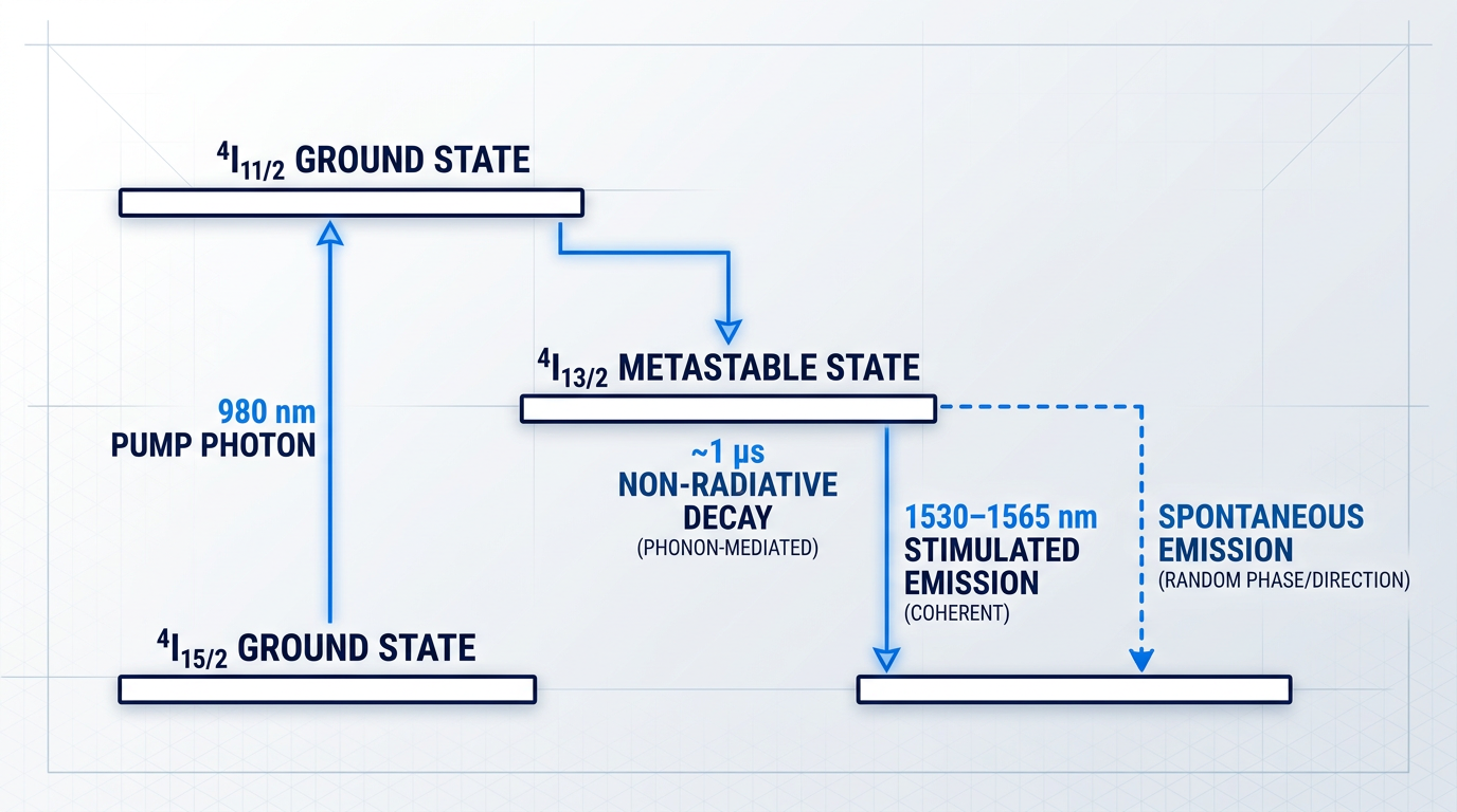
The diagram above captures the essential geometry of EDFA operation: ions are pumped up to the top level, fall quickly to the middle, and linger there long enough to be stimulated into emitting signal photons.
Pump Excitation and Non-Radiative Decay
The amplification cycle begins when a 980 nm pump photon is absorbed by a ground-state Er³⁺ ion, exciting it to the upper pump state (⁴I₁₁/₂).
From there, the ion does not emit a photon — instead, it undergoes non-radiative decay, transferring its excess energy to lattice vibrations (phonons) in the surrounding glass and dropping to the metastable state (⁴I₁₃/₂) within approximately 1 µs.
This fast, phonon-mediated transition is critical to the pump scheme: because ions pass through the upper pump state so rapidly, they never accumulate there in significant numbers, and the 980 nm pump photons are not reabsorbed by already-excited ions at that level.
Population Inversion and the Metastable Lifetime
Population inversion is the condition in which more ions occupy the excited metastable state than the ground state — and it is the prerequisite for net optical gain.
Achieving it in erbium is possible because the ⁴I₁₃/₂ metastable state has an unusually long radiative lifetime of approximately 10 ms, roughly four orders of magnitude longer than the ~1 µs non-radiative decay from the upper pump state above it.
That asymmetry is the key: ions drain quickly from the upper pump state into the metastable state, then drain slowly from the metastable state to the ground state, so the metastable population builds up under sustained pumping.
Without the unusually long lifetime of the 4I13/2 state, ions would decay back to the ground state before population inversion could be established — and the gain medium would absorb the signal rather than amplify it.
Once population inversion is established, a signal photon entering the gain fibre is more likely to encounter an excited ion and stimulate emission than to be absorbed by a ground-state ion — the medium transitions from absorber to amplifier.
Stimulated Emission: The Amplification Mechanism
When a signal photon at 1530–1565 nm encounters an Er³⁺ ion in the metastable state, it triggers stimulated emission: the ion drops to the ground state and releases a second photon with the same wavelength, the same phase, and the same propagation direction as the incoming photon.
The result is two coherent photons where there was one — and as those two photons propagate further through the erbium-doped fibre, each can stimulate additional emissions, producing the cascade of coherent photons that constitutes optical gain.
The coherence property is what makes stimulated emission useful for signal amplification rather than mere light generation: the emitted photon is a faithful copy of the signal photon, preserving its wavelength and phase information rather than adding noise.
Spontaneous Emission: The Noise Mechanism
Ions in the metastable state do not always wait for a signal photon — they can also decay spontaneously, emitting a photon at a random phase, in a random direction, and at a random wavelength within the gain band.
These spontaneous emission photons are incoherent: they carry no signal information and do not add to the signal, but they do propagate through the gain medium and get amplified, producing amplified spontaneous emission (ASE).
The contrast between the two processes is fundamental: stimulated emission is coherent and signal-building; spontaneous emission is incoherent and noise-building — and ASE is the irreducible noise floor of any EDFA, regardless of design.
The Glass Host and Gain Bandwidth
In isolation, the ⁴I₁₃/₂ → ⁴I₁₅/₂ transition of a free Er³⁺ ion would produce emission at a narrow set of discrete wavelengths — but in silica glass, the gain spectrum is spread into a smooth band spanning roughly 30 nm.
Two broadening mechanisms drive this. Homogeneous broadening occurs because phonon interactions in the glass perturb each ion's transition energy, widening its individual emission line. Inhomogeneous broadening occurs because the amorphous (non-crystalline) silica structure places each ion in a slightly different local environment, shifting the centre frequency of individual ions across the ensemble.
The combined result is a gain bandwidth broad enough to simultaneously amplify dozens of closely-spaced WDM channels — a property that would be impossible if erbium emitted only at discrete, narrow lines.
4f Electron Shielding and Host Stability
One might expect that embedding erbium in different glass hosts would shift the emission wavelength significantly — but in practice the 1530–1565 nm operating band remains stable across a wide range of host materials.
The reason lies in the atomic structure of the Er³⁺ ion: the transitions responsible for optical gain occur within the 4f electron shell, which sits deep inside the ion and is shielded from the surrounding lattice by the outer 5s and 5p electron shells.
Those outer shells act as a buffer — they absorb most of the crystal field perturbations from the host material before they can reach the 4f electrons, so the transition energies (and therefore the emission wavelength) remain approximately constant regardless of what glass the erbium is doped into.
This 4f shielding is what makes erbium uniquely well-suited to silica fibre: the gain wavelength is predictable and host-robust, which means the same fundamental physics applies whether the fibre is standard germanosilicate, aluminium-co-doped, or fluoride-based.
With the energy-level physics established, the next question is why the ⁴I₁₃/₂ → ⁴I₁₅/₂ transition happens to emit at 1530–1565 nm — and why that specific wavelength range turns out to be the most advantageous possible window for long-haul fibre transmission.
Why EDFAs Operate at 1550 nm
The 1550 nm operating wavelength of a fiber optic sensor amplifier based on erbium doping is not a convention inherited from early engineering decisions — it is a direct consequence of two independent physical facts converging at the same point on the spectrum: the minimum-loss window of silica optical fibre, and the emission band of the Er³⁺ ion.
Silica Fibre Attenuation and the 1550 nm Window
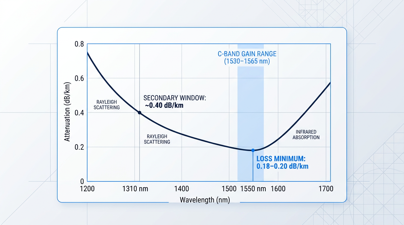
Single-mode silica optical fibre does not transmit all wavelengths equally — its attenuation spectrum is shaped by the competing effects of Rayleigh scattering at shorter wavelengths and infrared absorption at longer wavelengths, with the two curves intersecting to produce a loss minimum near 1550 nm.
At that minimum, high-quality single-mode fibres achieve attenuation values of approximately 0.18–0.20 dB/km, with ultra-low-loss variants reaching below 0.15 dB/km — and recent experimental fibres as low as 0.1406 dB/km at 1550 nm.
The practical consequence is reach: at sub-0.2 dB/km loss, signals can travel tens to hundreds of kilometres between amplification points, enabling transoceanic cable runs that would be physically impossible at higher-loss wavelengths.
Erbium's Gain Spectrum Aligns With the Loss Minimum
As established in the preceding section on erbium physics, the ⁴I₁₃/₂ → ⁴I₁₅/₂ transition of Er³⁺ in silica glass produces emission spanning approximately 1530–1565 nm — a range of roughly 35 nm in the conventional band.
That emission band sits precisely within the fibre's minimum-loss window — and this alignment is not coincidental: it reflects the physics of both the silica host and the rare-earth ion, and it is the reason erbium became the dominant dopant for long-haul telecommunications amplifiers.
The erbium ⁴I₁₃/₂ → ⁴I₁₅/₂ emission band (1530–1565 nm) coincides with the minimum-loss window of silica fibre (sub-0.20 dB/km). No other rare-earth dopant in a silica host replicates this alignment — which is why erbium is irreplaceable in long-haul fibre amplification.
C-Band and L-Band: The Two EDFA Operating Bands
The C-band (Conventional band), spanning 1530–1565 nm, is the primary operating range for EDFA-based systems and corresponds directly to the peak of erbium's gain spectrum in Al/P-doped silica glass.
The L-band (Long band), spanning 1565–1625 nm, also falls within erbium's gain spectrum and is accessible with a longer length of erbium-doped fibre operated at a lower population inversion level — typically around 30–40% — which shifts gain toward longer wavelengths.
Both bands are deployed in modern WDM and DWDM systems, though C- and L-band amplifiers are generally implemented as separate units, each optimised for its respective wavelength range.
| Parameter | 1310 nm Window | 1550 nm C-Band Window |
|---|---|---|
| Attenuation (standard SMF, max) | ~0.40 dB/km (ITU G.652) | ~0.20 dB/km (ITU G.652); <0.15 dB/km ultra-low-loss |
| Chromatic dispersion (standard SMF) | ~0 ps/nm/km (zero-dispersion wavelength) | ~17 ps/nm/km (anomalous dispersion, G.652) |
| Rare-earth amplifier in silica host | None with practical commercial deployment | Erbium (EDFA): widely deployed, C-band and L-band |
| Amplifier dopant candidate | Praseodymium (requires fluoride glass host) | Erbium (silica host; standard fibre infrastructure) |
Numerical comparison of the 1310 nm and 1550 nm transmission windows across attenuation, chromatic dispersion, and EDFA amplifier availability — to quantify why the 1550 nm window prevailed for long-haul systems.
The table makes the trade-off concrete: the 1310 nm window offers near-zero chromatic dispersion in standard single-mode fibre, which is attractive for short-haul applications, but its roughly 2× higher attenuation compared to 1550 nm means signals attenuate far more rapidly over distance.
More critically, there is no practical erbium-equivalent for 1310 nm amplification in a silica host — the gap that ultimately determined which window would dominate long-haul network architecture.
The 1310 nm Limitation: Praseodymium's Shortfall
Praseodymium (Pr³⁺) is the candidate rare-earth dopant for amplification near 1300 nm, and praseodymium-doped fibre amplifiers (PDFAs) with 1280–1320 nm bandwidth have been demonstrated experimentally.
However, praseodymium requires a fluoride glass host — specifically ZBLAN-type fibres — rather than silica, because the high phonon energy of silica quenches the relevant radiative transition non-radiatively.
This host requirement introduces significant practical barriers: fluoride fibres are mechanically fragile, difficult to splice to standard silica infrastructure, and expensive to manufacture — factors that have kept PDFAs from achieving the commercial deployment scale of EDFAs.
Absent a minimum-loss window alignment comparable to erbium at 1550 nm, and burdened by the fluoride host constraint, the 1310 nm window has remained a secondary transmission channel rather than the primary route for long-haul capacity.
One Amplifier, Dozens of Channels: The WDM Advantage
The ~35 nm gain bandwidth of an EDFA across the C-band is wide enough to simultaneously amplify every WDM channel present within that range — the amplifier count does not scale with channel count.
Commercial DWDM systems exploit this directly: a single C-band EDFA can support 40 to 96 channels at 50 GHz channel spacing, delivering per-fibre capacities of several terabits per second through one amplifier stage.
This is the foundational enabler of modern optical network capacity scaling — and it is only possible because erbium's gain window aligns with the fibre's low-loss transmission band, allowing all channels to travel efficiently and be amplified together.
It also means that any non-uniformity in the EDFA's gain profile affects every channel simultaneously — a consequence that makes gain flatness across the C-band a critical engineering challenge, covered in detail later in this guide.
Amplification outside the 1550 nm window requires alternative rare-earth dopants: thulium for the S-band (approximately 1460–1530 nm) and praseodymium for the 1300 nm region — both of which have seen limited commercial deployment and present ongoing manufacturing and handling challenges that §10 addresses in full.
With the wavelength rationale established, the next question is how an EDFA is physically constructed to exploit it — specifically, what pump laser excites the erbium ions and what other components are required to make the system work reliably.
Pump Lasers and EDFA Components: Design and Trade-offs
Understanding why erbium produces gain at 1550 nm is one thing; building a device that reliably exploits that gain across millions of hours of continuous operation is another problem entirely. The physics sets the boundaries — the engineering decides whether you stay inside them.
Every practical fiber optic sensor amplifier based on erbium doping begins with a single decision that cascades through the entire design: which wavelength to use for the pump laser.
Pump Laser Selection: 980 nm vs. 1480 nm
Two pump wavelengths dominate commercial EDFA design: 980 nm and 1480 nm. They are not interchangeable choices that happen to produce the same result by different routes — they produce genuinely different amplifiers, with different noise figure floors, different optical efficiencies, and different practical trade-offs that propagate through every downstream design decision.
At 980 nm pumping, the excitation follows a three-level pathway. Pump photons lift erbium ions from the ground state (⁴I₁₅/₂) to the upper pump level (⁴I₁₁/₂), from which they decay non-radiatively to the metastable ⁴I₁₃/₂ state. The critical detail is the timescale mismatch: the upper pump level lifetime is approximately 1 µs, while the metastable lifetime is approximately 10 ms — four orders of magnitude longer.
That timescale gap is what makes 980 nm pumping so effective at achieving near-complete population inversion. Ions drain out of the upper pump level almost instantly relative to how long they sit in the metastable state, so under sustained pumping the metastable level fills to near-capacity.
The energy gap between the upper pump level and the metastable state is substantial — approximately 0.4 eV — giving a Boltzmann factor β ≈ 0, meaning essentially no ions remain thermally distributed back into the lower sublevel of the metastable band.
The noise consequence is direct: with near-complete inversion, the spontaneous emission factor n_sp approaches 1, enabling noise figures below 4 dB — close to the 3 dB quantum limit. This is why 980 nm is the pump wavelength of choice wherever noise figure is the primary design constraint.
At 1480 nm pumping, the pathway is fundamentally different. Pump photons carry enough energy to excite erbium ions directly into the upper portion of the metastable ⁴I₁₃/₂ band, bypassing the intermediate ⁴I₁₁/₂ level entirely — a configuration sometimes described as quasi-two-level because the pump and signal transitions share the same energy manifold.
The consequence is only partial population inversion. Within the ⁴I₁₃/₂ manifold, ions thermalise toward the lowest sublevels according to the Boltzmann distribution. At 1480 nm, the Boltzmann factor β is approximately 0.4, meaning a meaningful fraction of ions occupy the lower sublevel of the metastable state and can re-absorb signal photons rather than amplify them.
This partial inversion imposes a noise figure penalty: typical minimum noise figures for 1480 nm-pumped EDFAs are around 5.5 dB, compared to below 4 dB for 980 nm. SPIE literature on EDFA pump physics notes that the noise figure is predicted to be up to 3 dB higher for 1480 nm pumping than for 980 nm pumping.
The historical context matters here. The 1480 nm pump wavelength was the first to reach commercial availability, primarily because high-power 1480 nm laser diodes were more mature and resilient in the early years of EDFA deployment — capable of output powers in the 200–400 mW range before equivalent 980 nm reliability was achieved. That early availability drove initial adoption, even though 1480 nm carried an inherent noise disadvantage.
Today, 980 nm pump laser technology has matured substantially, and most current commercial EDFAs use 980 nm pumping — sometimes in combination with 1480 nm in multi-stage architectures. The conversion efficiency picture, however, still favours 1480 nm: because 1480 nm pump photons are closer in energy to the 1550 nm signal photons, a higher fraction of pump energy is directly convertible to signal gain.
| Parameter | 980 nm Pump | 1480 nm Pump |
|---|---|---|
| Excitation pathway | Three-level: ground state → ⁴I₁₁/₂ → ⁴I₁₃/₂ metastable | Quasi-two-level: ground state → upper ⁴I₁₃/₂ manifold directly |
| Boltzmann factor β | β ≈ 0 (near-complete inversion) | β ≈ 0.4 (partial inversion; lower sublevel ions can re-absorb signal) |
| Minimum noise figure | < 4 dB | ~5.5 dB |
| Optical conversion efficiency | ~35% | ~50% |
| Commercial status | Dominant choice in current commercial EDFAs | First commercially available; used in booster stages and hybrid designs |
Side-by-side comparison of 980 nm and 1480 nm pump wavelengths across key EDFA performance parameters, sourced from UCSB ECE228B Blumenthal lecture slide data.
The table makes the trade-off concrete: 980 nm wins on noise figure by a margin that is significant in any system where amplifier noise accumulates across cascaded spans, while 1480 nm delivers higher optical-to-optical conversion efficiency.
Pump selection is therefore an engineering decision, not a default. Pre-amplifier stages — where a weak incoming signal must be boosted with minimal noise addition — strongly favour 980 nm. High-power booster stages, where efficiency matters more than the last fraction of a decibel in noise figure, may favour 1480 nm or a hybrid approach combining both wavelengths in separate stages.
Core EDFA Components and the Problems They Solve
With the pump laser selected, the remaining design task is assembling the components that allow pump energy to reach the erbium ions, keep the amplification process stable, and deliver a clean output signal. Each element in the chain exists to solve a specific engineering problem — none is present by convention.
Erbium-Doped Fibre
The erbium-doped fibre (EDF) is the gain medium: typically 5–30 m of single-mode silica fibre with Er³⁺ ions doped into the core at parts-per-million concentrations. The engineering problem it poses is co-optimisation: fibre length must be matched to pump power.
Gain builds along the fibre as pump photons invert the erbium population, reaches a peak at an optimal length where the pump is efficiently absorbed, then rolls off as pump photons are exhausted and the fibre transitions from a gain medium to an absorber.
Both fibre length and pump power must be optimised together for each specific amplifier design — neither is a fixed parameter that can be set independently of the other.
Host material composition also matters. Co-doping with aluminium (producing alumino-germanosilicate fibres) broadens and flattens the erbium gain spectrum compared to pure silica or germanium-doped hosts, which is directly relevant to the gain flatness challenge in WDM and DWDM systems — a topic addressed in depth later in this guide.
WDM Coupler
The WDM coupler solves the problem of combining two optical signals at very different wavelengths — pump and signal — onto a single fibre before they enter the EDF, with minimal power loss.
A broadband 3 dB coupler cannot do this job: it would split 50% of both pump and signal power to the unused port, introducing a 3 dB combination loss that is unacceptable in a low-noise amplifier. The WDM coupler is wavelength-selective — a dichroic design that routes the pump wavelength and the signal wavelength to the same output port with low excess loss, preserving both for amplification.
Placement of the WDM coupler is configuration-dependent: it appears at the input of the EDF for forward pumping, or at the output for backward pumping. That placement choice is the subject of the pumping configurations discussion that follows this section.
Optical Isolators
In a high-gain amplifier, any back-reflection of the amplified signal or amplified spontaneous emission (ASE) back into the gain medium can cause the device to oscillate — effectively turning the amplifier into a laser, which destroys its function as a linear amplifier and severely degrades noise performance.
Optical isolators prevent this by transmitting light in one direction only, via a directional optical effect based on Faraday rotation of polarisation. They are placed at the input (blocking back-reflections from upstream components re-entering the EDF) and at the output (blocking downstream reflections from re-entering). Their insertion loss — typically in the range of 0.5–1 dB — must be budgeted into the amplifier's overall noise figure calculation.
Optical Bandpass and Gain-Flattening Filter
The optical filter at the EDFA output serves two related but distinct functions. As a bandpass filter, it suppresses out-of-band ASE — spontaneous emission from the EDF that falls outside the signal band, consumes output power, and degrades the optical signal-to-noise ratio.
As a gain-flattening filter (GFF), it carries a loss profile engineered to be the inverse of the EDFA's non-uniform gain spectrum, equalising gain across the C-band so that all WDM channels receive comparable amplification. Not every EDFA includes a GFF — it is added when gain flatness is required by the application, typically in WDM and DWDM systems where unequal channel gain accumulates to unacceptable levels across cascaded amplifier spans.
The specific filter technologies used to achieve gain flattening are covered in detail later in this guide. For now, the key point is that the filter's role is defined by the application: suppressing noise in all cases, equalising gain when the system demands it.
The noise figure advantage of 980 nm and the efficiency advantage of 1480 nm represent a genuine engineering trade-off with no universal answer — and whichever wavelength is selected, it directly determines how the EDF length, WDM coupler placement, and filter requirements are specified. There is no pump choice that is simply 'correct' independent of application context.
Together, these four components — the erbium-doped fibre, the WDM coupler, the optical isolators, and the bandpass or gain-flattening filter — form a coherent system rather than an arbitrary collection of parts, with the pump laser choice influencing how each is specified and placed.
With the components understood, the next design question is how they are physically arranged relative to the direction of signal propagation — which is where forward, backward, and bidirectional pumping configurations enter the picture.
See EDFA Technology Built for Real Applications
The physics is clear — now see how it translates into hardware. Explore tailored EDFA solutions designed to specification, or download the EDF100 datasheet for a concrete look at real-world performance.

EDFA Pumping Configurations: Forward, Backward, Bidirectional
Pump direction is not a wiring detail — it is the variable that determines how population inversion is distributed along the erbium-doped fibre, and that spatial distribution drives every meaningful difference in noise figure and output power between configurations.
Once you understand what the inversion profile looks like under each configuration, the correct choice for any given amplifier role follows from physics rather than convention.
Forward (Co-Propagating) Pumping
In forward pumping, the pump laser is injected at the signal input end of the EDF so that pump and signal travel in the same direction — co-propagating through the fibre.
The critical consequence is spatial: the pump is freshest, and population inversion is highest, at the very point where the signal first enters the EDF and is at its weakest.
Amplifying a weak signal in a high-inversion region minimises the spontaneous emission added per unit of gain — this is the physical reason forward pumping delivers the lowest noise figure of the three configurations, making it the preferred choice for pre-amplifiers where noise figure is the dominant engineering constraint.
Backward (Counter-Propagating) Pumping
In backward pumping, the pump laser enters the EDF from the output end, travelling in the opposite direction to the signal — counter-propagating.
The inversion profile is now reversed: population inversion peaks at the output end where the signal is already strong, while the signal enters a comparatively low-inversion region at the input end, adding more noise early in the amplification process.
The compensating advantage is that because the pump is strongest where the signal is strongest, the amplifier can sustain significantly higher saturated output power before gain compression sets in — making backward pumping the natural fit for booster amplifiers where output power, not noise figure, is the primary requirement.
Bidirectional Pumping
Bidirectional pumping places pump lasers at both ends of the EDF simultaneously — one co-propagating with the signal, one counter-propagating — so the inversion profile reflects contributions from both ends.
The forward pump preserves high inversion at the signal input end, protecting noise figure where the signal is weakest; the backward pump sustains high inversion at the output end, supporting high saturated output power where the signal is strongest.
This dual-pump architecture is the configuration that most effectively combines both properties, which is why it is the preferred choice for high-performance in-line amplifiers where both noise figure and output power are simultaneously constrained.
The trade-off is real: bidirectional pumping requires two pump laser modules and two WDM couplers, increasing component count and system cost in ways that single-pump deployments avoid.
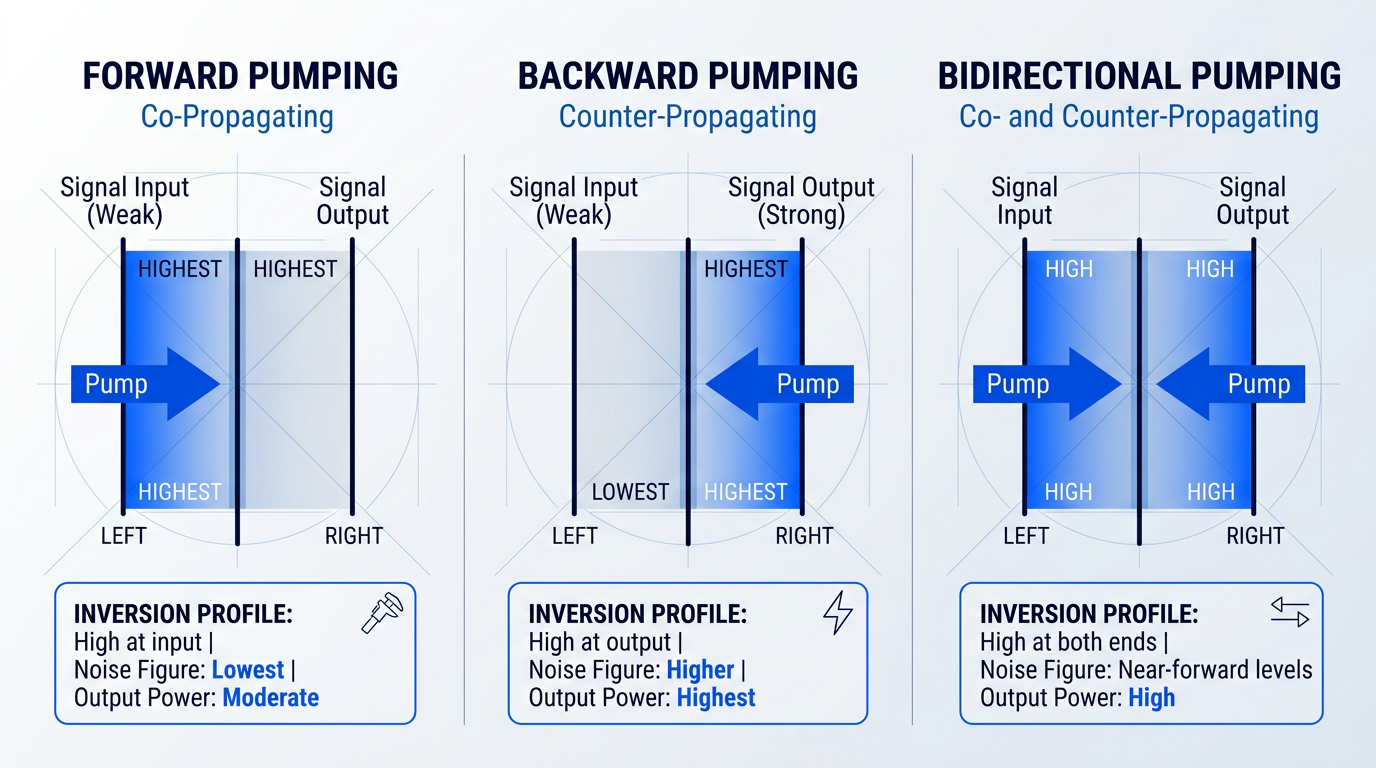
Across all three configurations, gain is not monotonically increasing with EDF length — it peaks at an optimal fibre length for a given pump power, then rolls off sharply as pump photons are exhausted and the distal fibre transitions from net gain to re-absorption of signal photons.
This means each configuration demands its own co-optimisation of EDF length and pump power: the optimal fibre length for a backward-pumped booster at a given pump power is meaningfully different from that of a forward-pumped pre-amplifier operating under the same pump conditions.
| Configuration | Noise Figure Profile | Output Power Capability | Component Count | Preferred Application |
|---|---|---|---|---|
| Forward (co-propagating) | Lowest of the three; high inversion at input minimises early-stage noise | Moderate; pump depletes toward output end, limiting peak output | 1 pump laser, 1 WDM coupler | Pre-amplifier (weak input signal, NF-critical) |
| Backward (counter-propagating) | Higher than forward; low inversion at input adds noise early | Highest single-pump capability; pump strongest where signal is strongest | 1 pump laser, 1 WDM coupler | Booster amplifier (strong input, high output power required) |
| Bidirectional | Near-forward-pump levels; forward pump protects input-end inversion | High; backward pump sustains output-end inversion for power | 2 pump lasers, 2 WDM couplers | In-line amplifier (balanced NF and output power both required) |
Comparison of the three EDFA pumping configurations across noise figure profile, output power capability, component count, and preferred amplifier deployment role.
The pattern the table reveals is that bidirectional pumping is not the default answer simply because its performance profile is the most complete — the two-pump architecture carries real cost and integration overhead that only in-line amplifier deployments typically justify.
For single-pump designs, the choice between forward and backward pumping is a direct function of which performance axis the application prioritises: noise figure for pre-amplifiers, saturated output power for boosters — and neither configuration is a compromise of the other.
The noise figure differences between configurations established here are comparative and qualitative; the next section examines what noise figure represents physically, how amplified spontaneous emission accumulates in cascaded amplifier chains, and how optical signal-to-noise ratio serves as the system-level metric that ultimately governs transmission reach.
ASE, Noise Figure, and OSNR in EDFAs
An EDFA can deliver 30 dB of gain and still fail a system — not because the signal is too weak at the receiver, but because the noise floor has risen to meet it. Noise performance determines system reach, sets the ceiling on WDM channel count, and ultimately governs whether a given bit-error rate is achievable at all.
Amplified spontaneous emission (ASE) is the dominant noise mechanism in EDFAs. Whenever erbium ions occupy the excited ⁴I₁₃/₂ metastable state, quantum probability dictates that some fraction will emit photons spontaneously — not triggered by an incoming signal photon, but by the fundamental statistics of the excited-state population.
Those spontaneously emitted photons travel through the gain medium and are themselves amplified, producing a broadband, incoherent noise floor that spans the entire C-band gain bandwidth and co-propagates with the signal.
ASE cannot be eliminated — and this is not a design limitation but a physical constraint. Population inversion is the prerequisite for stimulated emission and optical gain; it is also, unavoidably, the source of spontaneous emission. What engineers can manage is the degree to which ASE accumulates, through choices of pump power, fibre length, inversion level, and optical filtering — but the noise itself is always present.
Noise Figure: Quantifying Amplifier-Level Noise
The noise figure (NF) is the device-level metric that quantifies how much an amplifier degrades the signal-to-noise ratio. Defined as the ratio of input SNR to output SNR and expressed in decibels, it is always greater than zero — every real amplifier adds noise, so SNR always exits the amplifier lower than it entered.
The noise figure is directly tied to the spontaneous emission factor (n_sp), defined as (N₂ − N₁) / N₂, where N₂ is the population of the upper metastable state and N₁ is the population of the lower ground state. According to UCSB ECE228B lecture data (Blumenthal), NF equals 2·n_sp in linear terms, giving a theoretical minimum of 3 dB when n_sp = 1.
When inversion is complete and N₁ approaches zero, n_sp approaches 1 and NF approaches its 3 dB quantum minimum — the regime achieved by 980 nm pumping, which drives near-complete population inversion.
When inversion is partial — as with 1480 nm pumping, where ions are promoted directly into the metastable state with a non-zero Boltzmann population remaining in the lower level — N₁ is greater than zero, n_sp exceeds 1, and NF rises accordingly. The Blumenthal pump source data confirms this: 980 nm-pumped EDFAs achieve a minimum NF below 4 dB, versus 5.5 dB for 1480 nm-pumped equivalents.
NF is especially critical in pre-amplifier stages, where the input signal is at its weakest. Noise added at the front end is amplified by every subsequent stage in the chain, making the first-stage NF the single most influential factor in overall system noise performance.
| Parameter | 980 nm Pump | 1480 nm Pump |
|---|---|---|
| Minimum noise figure | < 4 dB | 5.5 dB |
| Population inversion level | Complete (N₁ ≈ 0) | Partial (N₁ > 0) |
| n_sp at full inversion | Approaches 1 | Greater than 1 |
| Optical conversion efficiency | 35% | 50% |
| Primary application | Pre-amplifiers, low-NF stages | Booster amplifiers, high-power stages |
Comparison of noise figure and key performance parameters between 980 nm and 1480 nm pump wavelengths, sourced from UCSB ECE228B Blumenthal lecture data.
The trade-off is clear: 980 nm pumping wins decisively on noise figure by achieving near-complete population inversion, while 1480 nm pumping offers higher optical conversion efficiency. This is why hybrid configurations — 980 nm for the low-noise first stage, 1480 nm for the high-power second stage — are common in high-performance EDFA designs.
ASE Accumulation, OSNR, and System Reach
In a long-haul system, EDFA stages are concatenated across many fibre spans, with each amplifier compensating the loss of one span. The noise problem compounds with every stage: ASE generated by the first amplifier is not simply passed along — it is amplified by the second amplifier, then the third, accumulating with every span.
By the end of a long cascaded amplifier chain, the accumulated ASE can dominate the noise floor entirely, regardless of the signal power launched into the first span. This is why system reach in optically amplified networks is fundamentally a noise accumulation problem, not a power budget problem.
In a cascade of N equal amplifier spans, accumulated ASE noise grows proportionally with N. The ScienceDirect amplified systems reference confirms that OSNR falls by 10·log₁₀(N) dB as spans are added — so a system with 10 spans has 10 dB less OSNR than a single-span system at the same per-amplifier noise figure. This is the hard arithmetic that makes NF minimisation so consequential in long-haul design.
The governing system-level metric is the optical signal-to-noise ratio (OSNR) — the ratio of signal power to ASE noise power, measured at the receiver within a defined reference bandwidth (typically 0.1 nm). As confirmed by both the UCSB Blumenthal notes and the ScienceDirect amplified system reference, OSNR in a multi-span system depends on amplifier output power, noise figure, span loss, and number of spans.
In WDM deployments, channel count also enters the equation: more channels sharing the same amplifier means more ASE generated across the gain bandwidth, reducing the per-channel OSNR budget.
OSNR sets the maximum achievable bit-error rate (BER) for a given modulation format — there is a minimum OSNR below which reliable data recovery is impossible regardless of receiver quality. For NRZ modulation limited by ASE noise alone, an OSNR of approximately 18 dB in 0.1 nm bandwidth is required at the receiver for a BER of 10⁻¹². This makes OSNR the governing constraint on both system reach and maximum channel count in WDM deployments.
One further property of the EDFA works in its favour in WDM systems: the ⁴I₁₃/₂ metastable state has a carrier lifetime of approximately 10 ms, confirmed by multiple sources including the JILA thesis and ScienceDirect erbium fibre references. This is extremely long relative to data modulation timescales — the gain medium simply cannot respond fast enough to signal fluctuations to produce inter-channel crosstalk at data rates above a few Mb/s.
Semiconductor optical amplifiers (SOAs), by contrast, have carrier lifetimes in the nanosecond range — fast enough to follow signal modulation and produce cross-gain modulation between WDM channels. The EDFA's slow gain dynamics, often perceived as a limitation in other contexts, are a meaningful structural advantage in multi-channel WDM amplification.
With OSNR established as the governing constraint on system reach, the next challenge is ensuring that OSNR holds equally across every WDM channel — which requires confronting the EDFA's non-uniform gain spectrum and the engineering approaches used to flatten it.
Gain Flatness and WDM Channel Management
The OSNR degradation problem covered in §8 assumes every channel in a WDM system is treated equally by each amplifier. In practice, EDFAs do not amplify all wavelengths equally — and that asymmetry, compounding across every stage in a cascaded chain, is the engineering challenge that most sharply separates single-channel amplification from real multi-channel system design.
The physical origin lies in the structure of erbium's energy levels. The ⁴I₁₃/₂ metastable state responsible for stimulated emission is not a single discrete level but a manifold of closely spaced sublevels, split by the Stark effect from the local electric field of the glass host.
The amorphous silica host compounds this further: structural disorder introduces both homogeneous and inhomogeneous broadening, spreading the gain spectrum across a range of transition frequencies rather than concentrating it at one wavelength.
The result, as characterised in UCSB ECE228 course materials, is a gain spectrum with a pronounced peak at around 1530 nm and a semi-flat region spanning roughly 20–30 nm of usable optical bandwidth — the core of the C-band.
Critically, the shape of this spectrum is not fixed. It is a direct function of the inversion level — the fraction of erbium ions in the excited state — which means the gain profile shifts as operating conditions change.
Why Cascaded WDM Systems Magnify the Problem
In a single-amplifier system, a few dB of gain variation across the C-band is inconvenient but manageable through pre-emphasis at the transmitter. In a cascaded chain — the architecture of every long-haul and submarine link — the per-stage gain difference between channels compounds at every amplifier stage.
ScienceDirect's amplifier cascade analysis states this directly: if the gain difference between the best and worst channel is 1 dB at each stage, after 10 stages that difference escalates to 10 dB, leaving the weakest channel with a substantially inferior OSNR compared to the strongest.
A 1 dB gain difference between channels at each amplifier stage becomes a 10 dB power gulf after 10 stages — pushing the weakest channel below BER threshold while potentially driving the strongest into nonlinear impairment.
This is not a noise floor problem in isolation — it is a differential OSNR problem. Channels experiencing lower gain accumulate proportionally more ASE noise relative to signal power at every stage, accelerating their OSNR degradation beyond what the simple cascade arithmetic alone suggests.
The strongest channel faces the opposite hazard: over-amplification drives it into the nonlinear regime of the transmission fibre, generating cross-phase modulation and four-wave mixing products that corrupt adjacent channels.
Engineering Approaches to Gain Equalisation
The first and most intrinsic lever is inversion-level management. Because the gain spectrum's shape is a function of the fraction of erbium ions in the excited state, choosing the operating point carefully can minimise peak-to-valley ripple before any external filtering is applied.
UCSB ECE228 course materials confirm that operating at approximately 40–60% inversion typically yields the broadest gain with the lowest ripple — achieved by co-optimising the erbium-doped fibre length and pump power for a given signal load.
Where intrinsic optimisation is insufficient, the dominant extrinsic approach is the gain-flattening filter (GFF): an optical filter placed after the erbium-doped fibre whose wavelength-dependent loss profile is engineered to be the inverse of the EDFA's gain spectrum, attenuating high-gain wavelengths more than low-gain ones to produce a net flat output.
Several filter technologies have been successfully demonstrated for this purpose, each with distinct trade-offs in tunability, insertion loss, and implementation complexity.
- Chirped fibre Bragg gratings: Passive, low-insertion-loss reflective filters. Fixed gain profile; well-suited to static channel loading where the gain spectrum is stable and predictable.
- Long-period fibre gratings (LPFGs): Transmissive filters that couple light into cladding modes at specific wavelengths. Demonstrated to flatten EDFA gain with approximately 3 dB residual ripple across the C-band.
- Acousto-optic tunable filters (AOTFs): Electrically tunable; can be adjusted in real time. Higher complexity and insertion loss than passive gratings, but offer dynamic gain profile correction.
- Mach-Zehnder interferometer filters: One of the earliest demonstrated approaches; can achieve dynamic gain flatness independent of gain level when combined with appropriate fibre design.
The choice between these approaches involves genuine engineering trade-offs. Passive chirped FBGs and LPFGs offer low insertion loss and simplicity, but they are designed for a fixed gain spectrum — they cannot adapt when the operating point shifts.
This is where automatic gain control (AGC) becomes essential. In real WDM and DWDM networks operating under ROADM architectures, channels are added and dropped dynamically, continuously changing the total input power to each EDFA.
When total input power changes, the EDFA's operating point shifts, which in turn shifts the gain spectrum — perturbing the gain balance for all surviving channels even if a static GFF is in place. AGC circuits monitor input power and adjust pump power in real time to hold the gain constant regardless of channel loading, as noted in the UCSB ECE228 design parameter framework.
At the fibre fabrication level, host material engineering offers a complementary intrinsic approach. Co-doping the silica host with aluminium — producing alumino-germanosilicate fibre — modifies the local crystal field around the erbium ions, broadening and flattening the gain spectrum.
Research published in Optical and Quantum Electronics confirms that alumino-germanosilicate host material achieves the highest post-flattening gain (30 dB) and the lowest relative gain difference (1% with 30 FBGs) compared to conventional silica or fluoride hosts, with a flattened bandwidth of 28 nm — and that erbium-doped silica fibres with aluminium co-doping are capable of flatter and broader gain spectra in the 1545–1560 nm range than other co-dopant choices such as germanium or phosphorus.
In practice, the most robust designs layer these approaches: alumino-germanosilicate fibre for intrinsic broadening, inversion-level optimisation to minimise baseline ripple, a GFF for residual equalisation, and AGC to hold the operating point stable under dynamic channel loading.
Looking further, combining lumped EDFA amplification with distributed Raman amplification — which provides gain along the transmission fibre itself — can extend flat gain across both C and L bands, reaching spectral regions where EDFA gain is weakest. This hybrid architecture is explored more fully in the next section.
With the gain flatness challenge understood in full, the logical next question is how EDFAs are actually deployed in real systems — and where the limits of the technology lie. That is the territory of §10.
EDFA Deployment, Alternatives, and Technology Limits
Nine sections of physics, components, configurations, and noise engineering all converge on a single practical question: where are EDFAs actually deployed, and why did they displace every competing approach to long-haul signal amplification? The answers are inseparable from each other — the deployment contexts explain the commercial victory, and the commercial victory explains why understanding the technology's limits matters as much as understanding its strengths.
Every EDFA in a fibre link occupies one of three functional positions, and the engineering priorities of each position are distinct.
- Booster amplifier: Placed immediately after the transmitter; prioritises maximum output power to overcome multiplexer insertion loss and launch a high-power signal into the first span.
- In-line amplifier: Installed every 80–120 km along terrestrial links to compensate span loss of 20–30 dB; must balance output power and noise figure across cascaded stages.
- Pre-amplifier: Positioned at the receiver end before the photodetector; noise figure is the primary priority, as any ASE added here directly degrades receiver sensitivity.
These roles are engineering decisions, not a flat taxonomy. The pumping configuration chosen for each role reflects the priority: booster amplifiers frequently use 1480 nm pumping for its higher power efficiency, while pre-amplifiers favour configurations that minimise noise figure. In-line amplifiers must satisfy both constraints simultaneously, which is why state-of-the-art WDM systems require all three amplifier types to achieve low noise figure, high output power, and uniform gain.
Long-Haul, Submarine, and CATV Deployment
The commercial inflection point for EDFA technology arrived in 1996, when the TAT-12 transatlantic submarine cable became the first major transoceanic system to deploy EDFAs in place of electronic repeaters — less than ten years after Robert Mears first described the device.
TAT-12 marked the transition from laboratory demonstration to global infrastructure, but the commercial argument that sustained EDFA adoption in the decades that followed is the pay-as-you-grow architecture: once fibre spans and amplifiers are installed, additional WDM channels can be added simply by deploying new transmitters at the terminals, without touching the amplifier plant mid-span.
Underpinning this is format and bit-rate transparency — because an EDFA amplifies the optical field directly without decoding it, the amplifier infrastructure is agnostic to modulation format and data rate. A system upgraded from 10 Gb/s to 100 Gb/s per channel, or from NRZ to coherent QAM, does not require the amplifiers to be replaced. The capital investment in the amplifier plant is preserved across successive capacity generations.
In CATV and hybrid fibre-coax (HFC) networks, the deployment context differs from long-haul telecommunications but the amplifier role is equally well defined. Booster EDFAs at the cable headend amplify analogue and digital video signals — including AM-VSB and QAM formats — before distribution over single-mode fibre to remote optical nodes, where the signal is converted back to RF for delivery over coaxial cable to subscribers.
The HFC architecture uses the fibre segment for its low attenuation and high bandwidth over distances of many kilometres, with the coaxial segment handling final subscriber delivery. EDFAs in this context must satisfy demanding linearity and noise requirements for analogue video — a different set of constraints from those governing long-haul digital systems, though the underlying amplification physics is identical.
EDFAs Versus Electronic OEO Repeaters
Before EDFAs, long-haul fibre links depended on OEO (optical-electronic-optical) repeaters — devices that detected the incoming optical signal, converted it to an electrical signal for amplification and reshaping, then re-drove a laser to retransmit optically into the next span. Prior to the EDFA, transatlantic cables operated at 140 Mb/s and required submarine electronic repeaters every few tens of kilometres. The engineering burden of that approach was substantial.
The case for EDFAs over OEO repeaters rests on three structural advantages. First, a single EDFA simultaneously amplifies all WDM channels traversing the fibre, whereas an OEO repeater processes one channel at a time — a WDM system with N channels requires N repeaters at every regeneration site, while a single EDFA serves all N channels at once. Second, format and bit-rate transparency means the EDFA does not need replacing when the system is upgraded. Third, EDFA noise performance approaches the quantum limit, with practical devices achieving noise figures of 4–6 dB — a level of noise performance that electronic regeneration cannot match in an all-optical cascade.
In a WDM system, a single EDFA replaces an entire bank of OEO repeaters — one per channel — at every amplification site, while remaining transparent to every future capacity upgrade. The cost advantage grows with channel count and link length.
Honesty requires acknowledging what OEO repeaters did that EDFAs cannot. An electronic repeater performs full 3R regeneration — reamplification, reshaping, and retiming — which removes accumulated chromatic dispersion and nonlinear impairments at every site. EDFAs amplify the optical signal but do not regenerate it: dispersion, self-phase modulation, cross-phase modulation, and four-wave mixing accumulate along the link and must be managed through separate means, including dispersion compensation modules, careful fibre selection, and digital signal processing at the coherent receiver.
This limitation is not a flaw in the EDFA — it is an engineering boundary that the rest of the system is designed around. The disciplines of dispersion management and nonlinear impairment mitigation exist precisely because EDFAs made all-optical long-haul transmission practical, and the system-level engineering evolved to complement what the amplifier cannot do.
Beyond 1550 nm: Alternative Dopants and Technology Limits
Erbium's dominance as a dopant is inseparable from its alignment with the minimum-loss window of silica fibre at 1550 nm. When amplification is needed outside the C-band, alternative rare-earth dopants are required — but none of them enjoy the same convergence of gain wavelength and fibre transmission minimum that makes erbium so effective.
- Thulium (S-band): Operates in the S-band (approximately 1450–1490 nm). High-performance TDFAs require fluoride glass hosts such as ZBLAN, which offer lower phonon energy but are fragile and difficult to splice to standard silica infrastructure.
- Praseodymium (1300 nm region): Operates near 1310 nm, the zero-dispersion wavelength of standard SMF. Small-signal gains of ~30 dB and noise figures of 4–7 dB are achievable, but fluoride glass host requirements limit commercial deployment.
- Ytterbium (~1 µm, industrial): Operates near 1 µm — not a telecommunications device. Ytterbium-doped amplifiers are widely used in high-power industrial laser applications: materials processing, cutting, and welding.
The common thread limiting thulium and praseodymium amplifiers to niche deployment is the fluoride glass host. ZBLAN and related fluoride glasses offer the low phonon energy needed for efficient rare-earth emission at these wavelengths, but they are mechanically fragile — with fracture toughness, elastic modulus, and hardness all significantly inferior to silica — and splicing them to standard silica fibre infrastructure introduces practical difficulties that have constrained commercial uptake.
The 1310 nm case for praseodymium is instructive: operating at the zero-dispersion wavelength of standard single-mode fibre is a genuine technical advantage for high-speed links, yet the absence of a minimum-loss window alignment at 1310 nm (silica loss at 1310 nm is higher than at 1550 nm) and the fluoride glass host requirement together mean that PDFA-based systems have not achieved the commercial scale of EDFA-based C-band infrastructure.
Distributed Raman amplification addresses the wavelength flexibility problem from a different direction: rather than relying on a dopant with a fixed gain band, Raman amplification uses stimulated Raman scattering in the transmission fibre itself, with the gain band set by the pump wavelength — shifted approximately 100 nm to longer wavelengths. This means Raman gain can be positioned at almost any wavelength by choosing the appropriate pump, including the S-band and other regions where erbium provides little gain.
Critically, Raman amplification provides distributed gain along the transmission fibre rather than lumped gain at discrete amplifier sites. This reduces the average signal power variation along the span, lowers nonlinear impairments, and improves OSNR relative to lumped EDFA-only designs — an advantage that becomes decisive in ultra-long-haul systems where OSNR budgets are tight. Hybrid EDFA-Raman configurations, combining the high gain efficiency of EDFAs with the distributed noise advantage of Raman, are widely used in long-haul and submarine systems operating at high channel counts.
Raman amplification is a complement to EDFA technology, not a successor. The two approaches address different aspects of the amplification problem — EDFAs provide high, efficient, well-controlled lumped gain in the C- and L-bands; Raman provides wavelength-flexible distributed gain that improves the noise floor of the combined span. In practice, the most capable long-haul systems deploy both.
With the complete picture of EDFA deployment roles, the engineering case over OEO repeaters, and the honest limits of erbium-based amplification now established, the remaining question for engineers is how to translate that understanding into specification decisions — which is exactly where the conclusion picks up.
Ready to Put EDFA Technology to Work?
From long-haul networks to free-space optical links, the right EDFA is built to specification. Explore tailored solutions or speak directly with a laser communications engineer about your requirements.

Conclusion
Specifying and sourcing EDFA technology: what engineers should know
The physics of erbium-doped fibre amplification is settled science; what remains genuinely hard is translating that physics into a deployment that meets the specific noise, gain, and reach requirements of a real system.
Pump configuration, gain flatness, and OSNR budget are not decisions you make in isolation — each one shapes the others, and the right answer depends entirely on where in the link the amplifier sits and what the system around it demands.
For applications where those constraints are tight, a supplier who reasons at the system level is worth more than a datasheet.
Frequently asked questions about EDFA technology
Precise answers to the questions engineers and technical buyers most commonly ask about erbium-doped fibre amplifier operation, deployment, and limitations.
A fibre amplifier works through stimulated emission: erbium ions (Er³⁺) embedded in a silica fibre are excited to a metastable energy state by a pump laser, typically operating at 980 nm. When signal photons in the 1530–1565 nm range pass through, they stimulate those excited ions to release coherent photons at the same wavelength and phase, producing optical gain entirely within the fibre. The process requires no conversion to electrical form — there is no OEO (optical-electrical-optical) conversion at any stage. This all-optical architecture means the amplifier is transparent to data rate and modulation format, and it introduces far less noise and complexity than electronic regenerators, which must detect, reclock, and retransmit each signal individually.
The three EDFA deployment roles are defined by their position in the link and the performance parameter each one prioritises. A booster amplifier sits immediately after the transmitter and raises the signal to a high launch power before it enters the fibre span; it is optimised for maximum output power, and its noise figure is a secondary concern because the signal is still strong at this point. An in-line amplifier sits mid-span, typically every 80–120 km in a long-haul link, compensating for the cumulative attenuation the signal has suffered; it must balance output power and noise figure, since both matter across a cascade of multiple stages. A pre-amplifier sits at the receiver end and amplifies a weak, attenuated signal before it reaches the photodetector; here, noise figure is the critical specification, because any noise added at this stage directly degrades the optical signal-to-noise ratio (OSNR) at the point where the signal is most vulnerable.
Gain flatness matters because EDFAs do not amplify all wavelengths equally, and in a cascaded DWDM system that inequality compounds at every stage. The EDFA gain spectrum peaks naturally around 1530 nm and varies across the C-band, so even a 1 dB per-stage difference between two channels becomes a 10 dB power disparity after ten amplifier stages. The channel that receives less gain at each hop arrives at the receiver with severely degraded OSNR and may fall below the bit error rate (BER) threshold, making it effectively unusable. Gain flatness is therefore a system-level constraint, not a cosmetic specification: it directly governs how many spans a DWDM link can traverse before channel equalisation — through gain-flattening filters or dynamic gain equalisers — becomes necessary to keep all channels within an acceptable power and OSNR window.
Four factors set the practical reach ceiling of an EDFA-amplified fibre link. First, OSNR accumulation: each amplifier stage adds amplified spontaneous emission (ASE) noise to the signal, and the cumulative OSNR degradation sets a hard limit on how many spans can be traversed before the BER becomes unacceptable. Second, ASE noise itself — the fundamental noise floor generated by every EDFA, governed by its noise figure and output power — determines how quickly that OSNR budget is consumed. Third, nonlinear impairments: at the launch powers needed to maintain OSNR over long spans, fibre nonlinearities including self-phase modulation, cross-phase modulation, and four-wave mixing distort the signal; these effects worsen as channel count rises and channel spacing narrows in dense WDM systems. Fourth, chromatic dispersion causes pulse broadening that accumulates with distance and produces inter-symbol interference, requiring dispersion-compensating fibre or coherent digital signal processing in long-haul designs. Critically, EDFAs address attenuation only — they do not correct for dispersion or nonlinear distortion, which must be managed by separate means.
Yes, but with meaningful limitations depending on how far from the C-band the target wavelength lies. L-band extension (1565–1625 nm) is the most practical option: operating the erbium-doped fibre at lower inversion levels and using a longer EDF shifts the gain peak toward longer wavelengths. L-band EDFAs are commercially deployed and are commonly paired with C-band EDFAs to double system capacity on a single fibre. S-band amplification (approximately 1450–1490 nm) is achievable using thulium-doped fibre amplifiers (TDFAs), but these require fluoride glass or other specialised fibre hosts rather than standard silica, and commercial deployment remains limited. The 1300 nm region can be addressed with praseodymium-doped fibre amplifiers (PDFAs), which can reach small-signal gains of around 30 dB, but again require fluoride glass, are difficult to splice to standard silica fibre, and operate outside the minimum-loss transmission window that gives erbium its fundamental advantage at 1550 nm. For practical system design, C-band and L-band remain the commercially relevant operating ranges; amplification at other wavelengths carries significantly higher engineering complexity and lower commercial maturity.
No — fibre optic infrastructure is actively expanding, not declining. Global internet traffic growth continues to drive sustained investment in long-haul fibre networks, submarine cable systems, and metropolitan fibre deployments. EDFA-amplified long-haul networks remain the backbone of global telecommunications, and rather than being replaced, they are being upgraded with higher-capacity coherent transmission technologies that extract more throughput from existing fibre. The question often arises from interest in wireless and satellite alternatives such as 5G and low-earth-orbit satellite broadband, but these technologies complement rather than displace fibre: wireless backhaul itself depends heavily on fibre infrastructure to carry traffic between base stations and the core network. Fibre's fundamental advantages — high bandwidth, low loss, immunity to electromagnetic interference, and long-term scalability — are not replicated by any current wireless technology at comparable scale or cost.