

Introduction
Light loses power as it travels through fibre — not because of poor engineering, but because physics demands it. Over long distances, that loss becomes a hard limit on how far a signal can travel.
For network engineers and optical system designers, the question is how to push past that limit without converting every signal back to electronics just to amplify and retransmit it.
Erbium-doped fibre amplifiers solve that problem entirely in the optical domain — and understanding how they do it, beyond the block diagram, is what this guide is built for.
It moves from the physics of optical amplification through component architecture, performance characteristics, and real-world operational behaviour — theory and practical context together.
TL;DR
EDFA performance is an engineering outcome, not a fixed property of the technology. Every variable — pump wavelength, fibre design, control mode, integration quality — shapes the gain, noise, and stability the amplifier actually delivers. Engineers who understand the underlying mechanisms can navigate those trade-offs with confidence, rather than treating the datasheet as a black box.
This article covers:

Stimulated emission and population inversion: the physics of optical gain
Why erbium ions produce gain at 1550 nm
Internal EDFA components and their functional roles
Gain, noise figure, ASE, flatness, and saturation
Booster, in-line, and pre-amplifier deployment types
AGC, APC, ACC control modes and DWDM transients
What is the EDFA Working Principle?
Every optical signal weakens as it travels through fibre — attenuation is a physical inevitability. For decades, the only way to extend a signal's reach was to pull it out of the optical domain, amplify it electronically, and push it back into fibre as light. EDFA changed that equation entirely, making it possible to amplify optical signals directly, without ever leaving the fibre domain.
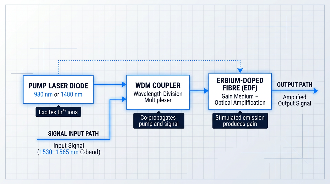
An erbium-doped fibre amplifier is an optical amplifier whose gain medium is a short length of silica fibre with trivalent erbium ions (Er³⁺) incorporated into its core. When the right pump light is injected, those erbium ions become capable of transferring energy to a passing optical signal, amplifying it directly in the optical domain with no electrical conversion at any stage.
The amplification window that erbium ions provide spans the C-band, roughly 1530–1565 nm — and that range is not incidental to EDFA's success.
The C-band (1530–1565 nm) coincides precisely with the lowest-attenuation transmission window of standard silica optical fibre. EDFA's gain spectrum aligns with the wavelength range where fibre loses the least signal — making it not merely a capable amplifier, but the right amplifier for the medium long-haul networks are built on.
Three core components work together to produce that amplification, and understanding their roles as a system is the starting point for the EDFA working principle.
- Erbium-doped fibre (EDF): The gain medium. A short length of silica fibre with Er³⁺ ions in its core, where optical amplification physically occurs.
- Pump laser diode: The energy source. Operates at 980 nm or 1480 nm, injecting light that excites erbium ions into a higher energy state.
- WDM coupler: The combiner. Merges the pump wavelength and the signal wavelength onto a single fibre so both enter the doped fibre together.
At a high level, the mechanism works as follows: the pump laser excites Er³⁺ ions into a higher energy state, and when signal photons arrive, they trigger stimulated emission — causing the excited ions to release additional photons at the same wavelength and phase as the incoming signal, producing optical gain.
The WDM coupler is what makes co-propagation of pump and signal practical: it routes two very different wavelengths onto the same fibre path so that both reach the doped region simultaneously, without requiring separate physical paths.
The practical consequence of this architecture was transformative for optical networking: EDFA eliminated the need for OEO regenerators at every span, replacing costly optical-electrical-optical conversion stages with a single all-optical amplification step that works across all wavelengths simultaneously.
This is what made large-scale DWDM networks economically and technically viable — dozens of wavelength channels amplified in a single pass through the same doped fibre, with no per-channel electronics required.
To understand precisely how stimulated emission produces that gain — and why the pump and signal interact with erbium ions the way they do — it helps to start with the quantum-mechanical process at the heart of the amplifier.
The Physics of Optical Amplification
To truly understand the EDFA working principle, you need to go one level deeper than the component diagram: into the quantum mechanics that makes optical amplification physically possible. Every design decision in an EDFA — the choice of gain medium, the pump architecture, the fibre length — traces back to three foundational phenomena: stimulated emission, spontaneous emission, and population inversion.
Stimulated Emission: One Photon In, Two Photons Out
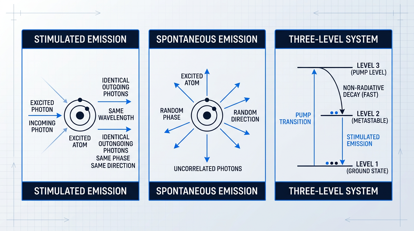
When an atom occupies an excited energy state and an incoming photon arrives with energy precisely matching the gap between that excited state and a lower energy level, the atom does not simply absorb the photon — it is stimulated to emit a second photon and drop to the lower state.
The emitted photon is identical to the incoming one: same wavelength, same phase, same polarisation, same direction of propagation. This is the mechanism of coherent optical amplification — the signal photon is not consumed, and the medium adds a new photon that is indistinguishable from the original.
This coherence is what separates an optical amplifier from a simple light source: the amplified output preserves the wavelength and phase characteristics of the input signal, which is precisely what long-haul transmission systems require.
Spontaneous Emission: The Unavoidable Source of Noise
Excited atoms do not wait indefinitely for an incoming photon. After a characteristic lifetime, an excited atom will decay on its own, releasing a photon of random phase and random direction — a process called spontaneous emission.
Unlike stimulated emission, spontaneous emission is not coherent amplification. The photons it produces are uncorrelated with the signal and contribute nothing useful to it. This is the physical origin of amplified spontaneous emission (ASE) noise: spontaneously emitted photons that propagate along the fibre axis get amplified by the same gain medium as the signal, adding a broadband noise floor to the output.
The balance between stimulated and spontaneous emission rates in the gain medium is what ultimately governs the noise performance of any optical amplifier — a point that will become critical when EDFA noise figure is examined later.
Population Inversion: The Necessary Condition for Net Gain
In thermal equilibrium, atoms overwhelmingly occupy the lowest available energy state — the ground state. A signal photon travelling through such a medium is far more likely to be absorbed by a ground-state atom (promoting it to the excited state) than to trigger stimulated emission from one of the relatively rare excited atoms.
The result is attenuation, not amplification. For a medium to amplify rather than absorb, the population distribution must be flipped: more atoms must reside in the excited state than in the ground state, a condition called population inversion.
Only when inversion is achieved does stimulated emission dominate over absorption, and the medium delivers net optical gain to a passing signal.
Without population inversion, any gain medium absorbs rather than amplifies. Every engineering decision in EDFA design — pump power, fibre length, doping concentration — ultimately serves one purpose: achieving and sustaining sufficient inversion across the signal bandwidth.
Why a Two-Level System Cannot Sustain Inversion
The obvious approach to creating population inversion is to shine pump light at the same wavelength as the signal transition, promoting ground-state atoms to the excited state. This is the two-level system scenario — and it is fundamentally self-defeating.
Every pump photon that promotes a ground-state atom upward also has a chance to stimulate emission from an already-excited atom, driving it back down. The pump simultaneously builds and destroys the inversion it is trying to create.
At best, the two processes reach equilibrium and the populations equalise — a condition known as transparency, where the medium neither amplifies nor absorbs. A true population inversion, with more atoms in the excited state than the ground state, is thermodynamically unreachable through optical pumping in a two-level system. This is why no practical laser or optical amplifier operates on a two-level scheme.
The Three-Level System: Decoupling Pump from Signal
The solution is to use a gain medium with at least three energy levels, so that the pump transition and the signal transition are distinct. In a three-level system, pump photons promote atoms from the ground state (level 1) to a short-lived upper pump level (level 3).
From level 3, atoms decay rapidly and non-radiatively down to an intermediate level (level 2), releasing their excess energy as heat or phonons rather than photons. This non-radiative decay is fast — much faster than the radiative lifetime of level 2.
Level 2 is the metastable level: atoms accumulate there because the downward radiative transition back to the ground state is comparatively slow. This accumulation is precisely what creates and sustains population inversion between level 2 and level 1.
Stimulated emission — and therefore optical gain — occurs on the transition from the metastable level back to the ground state. Because the pump drives a completely different transition (ground state to level 3), it does not directly stimulate emission on the signal transition, breaking the self-defeating cycle that makes two-level systems unworkable.
The Quasi-Three-Level System: Real-World Refinement
The ideal three-level model assumes the ground state is fully depopulated once inversion is established. In practice, most real gain media — including erbium in silica glass — do not behave this cleanly.
In a quasi-three-level system, the lower laser level sits close to or partially overlaps with the ground state manifold. This means some residual population always remains in the lower laser level at operating temperatures, and that population absorbs at the signal wavelength.
The practical consequence is a threshold effect: the pump must supply enough power to overcome this residual ground-state absorption before the medium delivers any net gain. Below threshold, the medium attenuates the signal; above it, gain builds with increasing pump power.
Keeping this quasi-three-level vocabulary in mind sets up the next section cleanly: the following section maps this general framework directly onto erbium's specific energy structure, explaining why the gain transition falls at approximately 1.55 µm and how the metastable lifetime of erbium ions makes it an exceptionally well-suited gain medium for optical amplification.
Erbium Energy Levels and the 1550 nm Gain Transition
The quasi-three-level framework established in the previous section is only half the story — the other half is why erbium, specifically, maps so perfectly onto it. The answer lies in a set of electronic energy levels that align with the lowest-attenuation window of silica fibre with almost suspicious precision, and in a host material whose structural disorder turns what would otherwise be a narrow laser line into a gain band wide enough to carry dozens of simultaneous WDM channels.
The Three Energy Levels That Matter
Three electronic states of the Er³⁺ ion govern EDFA operation: the ground state (⁴I₁₅/₂), where ions reside in the absence of pumping; the upper pump level (⁴I₁₁/₂), reached by absorbing 980 nm photons; and the metastable gain level (⁴I₁₃/₂), the intermediate state from which stimulated emission at ~1.55 µm occurs.
These three states are the concrete instantiation of the three-level system: ⁴I₁₁/₂ is the short-lived upper level, ⁴I₁₃/₂ is the metastable intermediate, and ⁴I₁₅/₂ is the ground state that ions must be lifted away from to achieve population inversion.
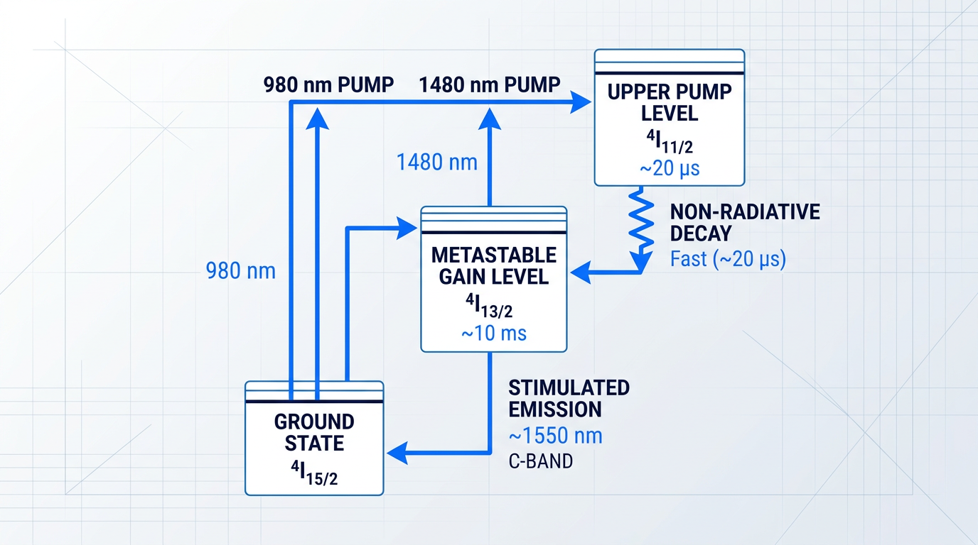
The sequence for 980 nm pumping runs as follows: pump photons excite ions from ⁴I₁₅/₂ to ⁴I₁₁/₂, from which they undergo rapid non-radiative (phonon-assisted) decay down to ⁴I₁₃/₂ on a timescale of roughly 20 µs.
The radiative lifetime of ⁴I₁₃/₂ is approximately 10 ms — three orders of magnitude longer than the non-radiative decay step above it.
Because the 4I13/2 level has a ~10 ms radiative lifetime, ions accumulate there far faster than they decay — sustaining population inversion continuously under steady pump illumination. Without this long-lived metastable state, stimulated emission could not dominate over absorption.
Population accumulates at ⁴I₁₃/₂ because ions arrive there quickly and leave slowly — the level acts as a reservoir that sustains population inversion under continuous pump illumination, allowing signal photons to trigger stimulated emission on demand.
Why 1480 nm Pumping Achieves Incomplete Inversion
The 1480 nm pump pathway is physically distinct: rather than exciting ions to ⁴I₁₁/₂ and relying on non-radiative decay to fill ⁴I₁₃/₂, 1480 nm photons drive transitions directly into the upper manifold of ⁴I₁₃/₂ itself.
Because the 1480 nm pump wavelength overlaps with the gain band, it can also stimulate emission from ⁴I₁₃/₂ back to ⁴I₁₅/₂ — a two-level-like dynamic that prevents complete population inversion from being achieved.
This is not a component quality limitation: it is a direct consequence of where the pump energy lands in the level structure. NIST SP 864 confirms that 980 nm pumping achieves higher population inversion than 1480 nm pumping for this exact reason, with the noise figure difference being a measurable outcome of the underlying physics.
Stimulated Emission at 1550 nm: Why This Wavelength
When a signal photon triggers stimulated emission from ⁴I₁₃/₂ to ⁴I₁₅/₂, the emitted photon carries energy corresponding to a wavelength of approximately 1.55 µm — placing it squarely within the C-band (1530–1565 nm) as defined by ITU-T standards.
As established in the background section, the C-band coincides with the lowest-attenuation window of silica fibre — which is why this alignment between erbium's gain transition and fibre's transmission minimum made EDFA the enabling technology for long-haul optical communications.
Why the Gain Spans 35 nm: Broadening in Silica Glass
A striking feature of the EDFA gain spectrum is its breadth: rather than amplifying a single discrete wavelength, erbium in silica glass produces gain across the full 35 nm C-band (1530–1565 nm), as confirmed by both ITU-T G-series standards and IEEE sources.
The physical origin of this bandwidth lies in the amorphous structure of the silica host. In a perfect crystal, all erbium ions would sit in identical environments, and the ⁴I₁₃/₂ and ⁴I₁₅/₂ levels would produce a sharp, discrete emission line.
In amorphous glass, each ion occupies a slightly different local structural site, which has two cascading effects on the emission spectrum.
First, the local crystal field at each site lifts the degeneracy of the ⁴I₁₃/₂ and ⁴I₁₅/₂ manifolds through Stark splitting, creating multiple sub-levels within each manifold. Transitions between different sub-level combinations produce photons at slightly different wavelengths, spreading the emission spectrum. As ScienceDirect's gain spectrum reference confirms, the EDFA gain bandwidth from ~1525–1565 nm arises primarily from this Stark splitting of the high-angular-momentum ground and first excited states.
Second, because the glass is amorphous rather than crystalline, each ion experiences a different local field strength — producing inhomogeneous broadening across the ensemble of ions. The NIST SP 792 characterisation work identifies this site-to-site fluctuation in Stark and phonon broadening as the main source of partial inhomogeneous broadening in erbium-doped fibres at room temperature.
Together, Stark splitting and inhomogeneous broadening convert what would be a narrow laser line into a gain spectrum spanning the full C-band — which is precisely what allows a single EDFA to simultaneously amplify many WDM channels carried on different wavelengths within that window.
Pump Wavelength and Co-Doping as Design Variables
With the energy-level physics established, the engineering trade-offs between pump wavelengths and fibre composition become reasoned choices rather than empirical rules.
- 980 nm pump: Excites ions to 4I11/2, enabling complete population inversion via non-radiative decay. Achieves noise figures closer to the 3 dB quantum limit; preferred where noise performance is the priority.
- 1480 nm pump: Pumps directly into the upper manifold of 4I13/2. Cannot achieve complete inversion, so noise figure is higher; favoured where maximising output power efficiency matters more.
- Aluminium co-doping: Al³⁺ ions modify the local crystal field around Er³⁺, enhancing inhomogeneous broadening and Stark splitting to produce a flatter, broader gain spectrum across the C-band.
The noise figure difference between pump wavelengths is not incidental: NIST SP 864 documents that 980 nm-pumped amplifiers typically achieve noise figures in the 3–4 dB range, while 1480 nm-pumped amplifiers typically measure 5–7 dB — a direct consequence of the incomplete inversion described above.
Aluminium co-doping operates through the same broadening mechanism that gives silica-hosted erbium its gain bandwidth in the first place. By further modifying the local crystal field environment, Al³⁺ ions enhance both inhomogeneous broadening and Stark splitting, producing a flatter gain profile across the C-band — a fibre design variable that engineers use to improve gain flatness without relying solely on external optical filters. Multiple peer-reviewed sources, including Springer Nanoscale Research Letters and SPIE proceedings, confirm that increasing Al³⁺ concentration progressively broadens and flattens the Er³⁺ emission spectrum.
These are not fixed properties of erbium amplifiers — they are outcomes of deliberate design choices in pump architecture and fibre composition, each traceable back to the energy-level structure described in this section.
With the erbium energy-level mechanism fully mapped — the transitions, the lifetimes, the gain bandwidth, and the design variables that shape them — the natural next question is how the physical components of an EDFA are arranged to exploit this physics in practice.
Core Components Inside an EDFA
The physics of stimulated emission and population inversion, established in the preceding sections, do not operate in the abstract — they are instantiated in a precise arrangement of optical components, each one performing a role that the underlying quantum mechanics demands.
Understanding those components as hardware expressions of physical necessity, rather than as an arbitrary parts list, is what separates a designer who can optimise an EDFA from one who can only assemble one.
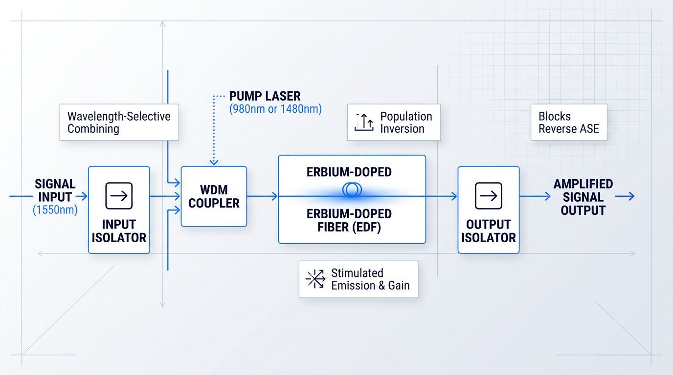
The schematic above traces the two paths through a forward-pumped EDFA: the signal enters from the left through an input optical isolator, the pump laser feeds into a WDM coupler that merges both wavelengths onto a single fibre, those co-propagating beams traverse the erbium-doped fibre (EDF) where amplification occurs, and the amplified signal exits through an output isolator.
Erbium-Doped Fibre: The Gain Medium
The erbium-doped fibre is the heart of the amplifier — a length of silica fibre whose germanium-doped core has been further doped with trivalent erbium ions (Er³⁺), the species whose energy level structure produces gain at 1550 nm.
Three interdependent design variables govern the EDF's performance: fibre length, erbium ion concentration, and pump power.
These three parameters interact tightly: higher ion concentration allows a shorter fibre to absorb the same pump power, but concentrations that are too high introduce ion-ion interactions that quench the excited state and reduce gain efficiency.
Pump power sets the inversion level along the fibre's length — and this is where an important design constraint emerges directly from the population inversion physics.
For any given pump power, there is an optimum EDF length. Too short, and pump light exits the fibre unabsorbed, wasting available inversion. Too long, and the distal end of the fibre — where pump power has been largely exhausted — is insufficiently inverted and becomes absorbing rather than amplifying, actively attenuating the signal it should be boosting.
This optimum-length principle means EDF design is an exercise in matching fibre length and ion concentration to the available pump power — a balance that must be re-evaluated whenever pump conditions change.
Pump Laser Diodes: Sustaining Population Inversion
Pump laser diodes are the power source that drives and sustains population inversion in the EDF — without them, the erbium-doped fibre is not a gain medium but an absorber, attenuating the signal at 1550 nm rather than amplifying it.
Operating at either 980 nm or 1480 nm (the wavelength choice and its energy-level rationale having been established in the previous section), these semiconductor laser diodes supply the optical power that lifts Er³⁺ ions into excited states and maintains the population inversion on which stimulated emission depends.
From a hardware perspective, the critical engineering reality is straightforward: pump power sets the inversion level, and inversion level determines available gain. Increasing pump current raises the proportion of ions in the excited state, deepening the inversion and increasing the gain the EDF can deliver to the signal.
Pump laser diodes are therefore not passive components — they are the active control input to the amplifier, and their output stability directly determines the stability of the gain.
WDM Coupler: Merging Pump and Signal
For amplification to occur, pump light and signal light must co-propagate through the same EDF — yet they arrive from different sources at different wavelengths.
The WDM coupler (wavelength-division multiplexing coupler) solves this by using wavelength-selective interference or evanescent coupling to route the pump wavelength and the signal wavelength onto a single output fibre with minimal insertion loss for either.
The distinction from a simple optical splitter matters considerably: a broadband splitter divides optical power by ratio, so a 50/50 splitter would immediately waste half the pump power and half the signal power before either reached the EDF.
A WDM coupler instead exploits the wavelength difference to route each beam selectively — the 980 nm or 1480 nm pump exits one port and the 1550 nm signal exits the same port, with each experiencing only the low insertion loss of the coupler itself rather than a 3 dB splitting penalty.
This wavelength-selective combining is what makes the co-pumped (forward-pumped) EDFA architecture practical at all: pump and signal enter the EDF together, fully powered, ready to interact.
Optical Isolators: Blocking Reverse Propagation
A high-gain medium in a fibre system creates a specific hazard: any light travelling in the reverse direction — back toward the signal source — will be amplified just as effectively as forward-travelling signal light.
Back-reflections from downstream connectors, splices, and interfaces inevitably return some fraction of the signal into the EDF travelling in reverse, where it seeds amplified spontaneous emission (ASE) feedback.
If that feedback grows sufficient, the EDFA transitions from a controlled amplifier into a laser cavity — an unstable condition that corrupts the signal and can damage upstream components.
Optical isolators are one-way valves for light, exploiting the Faraday effect to transmit light in the forward direction while blocking reverse-propagating light with high extinction (typically 40–50 dB of isolation).
An isolator at the input port protects the upstream system from the EDFA's own backward-propagating ASE, while the output isolator prevents downstream reflections from re-entering the gain medium.
Both isolators are functionally necessary: removing either one compromises the stability of the amplifier under real-world operating conditions where perfect reflectionless connections cannot be guaranteed.
Advanced Components: GFFs, VOAs, and Monitors
Beyond the four core components, practical EDFA designs incorporate additional elements that address gain non-uniformity, inter-stage power management, and closed-loop control.
- Gain-flattening filters (GFFs): Passive wavelength-selective filters that attenuate higher-gain wavelengths across the C-band, bringing the erbium emission profile closer to spectrally uniform gain.
- Variable optical attenuators (VOAs): Inserted at the mid-stage access point in two-stage designs to control inter-stage power and prevent the second gain stage from being driven into deep saturation.
- Optical taps and power monitors: 1–5% tap couplers divert a small signal fraction to photodetectors, feeding the control loops that maintain target gain or output power — covered in depth later.
Gain-flattening filters address a fundamental property of the erbium emission cross-section: it is not spectrally uniform across the C-band, so different WDM channels naturally receive different amounts of gain — a problem that compounds over multiple amplifier spans.
The gain non-uniformity that GFFs correct, and its quantitative implications for system design, is examined in detail in the next section on EDFA performance characteristics.
Optical taps and their associated photodetectors provide the power measurement signals that feed back into pump current control — the hardware foundation for the automatic gain and power control modes discussed later in this guide.
Multi-Stage Architecture and Mid-Stage Access
High-performance EDFA designs frequently use two gain stages in series rather than a single long EDF, with a deliberate access point between them.
This mid-stage access point is an architectural feature, not an afterthought: it allows high-loss in-line components — most commonly dispersion compensation modules (DCMs) — to be inserted between the two gain stages rather than outside the amplifier entirely.
A DCM can introduce 5–10 dB of insertion loss; placing it inside the amplifier chain means the second gain stage recovers that loss before the signal exits, preserving output power and limiting the noise figure penalty that would result from attenuating a fully amplified signal downstream.
Gain-flattening filters and VOAs are also commonly placed at this mid-stage access point, making the two-stage architecture a natural platform for integrating the full complement of advanced components described above.
With the physical architecture mapped out — each component grounded in the physics it serves — the natural next question is how these elements combine to determine what the amplifier actually delivers: its gain, its noise, and where the fundamental limits lie.
EDFA Performance: Gain, Noise, and Saturation
The physics of population inversion and stimulated emission, and the architecture that implements them, ultimately resolve into a handful of numbers on a datasheet: gain, noise figure, gain flatness, and saturated output power. Understanding where those numbers come from — and what moves them — is what separates a designer who can specify an EDFA from one who can engineer it.
Gain: A Design Variable, Not a Fixed Property
EDFA gain is the direct consequence of population inversion and stimulated emission along the erbium-doped fibre length: each signal photon triggers the emission of an identical photon from an excited erbium ion, and the process compounds over the full EDF length.
The gain achievable from a given EDFA is not a ceiling imposed by the technology — it is a design space defined by pump power, EDF length, erbium concentration, and input signal power, with practical small-signal gain spanning a wide range depending on how those variables are set.
As input signal power rises, the stimulated emission rate increases proportionally, and the population inversion begins to erode. The amplifier delivers less gain per unit of input — a behaviour that seeds the saturation discussion below.
Gain Spectrum and Flatness Across the C-Band
Gain across the C-band is not uniform. As established in the erbium energy-level discussion, Stark splitting and glass-host broadening produce a gain spectrum spanning roughly 35 nm — but the erbium emission cross-section varies with wavelength across that window, so different channels experience meaningfully different amounts of gain.
In a DWDM system, this non-uniformity is a fundamental problem: all channels must arrive at the receiver with approximately equal power. Even a modest gain deviation across the C-band means some channels are consistently over-amplified and others under-amplified.
The problem compounds with each cascaded amplifier stage. Channels that enter a chain with a slight power disadvantage accumulate a larger deficit at every hop, degrading their optical signal-to-noise ratio (OSNR) relative to the stronger channels.
This is not an engineering oversight — it is a physical consequence of the erbium emission cross-section shape. Without intentional equalisation, gain deviation across the C-band can be substantial enough to impair WDM channel balance in any real deployment.
Gain-flattening filters (GFFs) address this by introducing a complementary loss spectrum that attenuates the high-gain wavelengths, producing a net flat response across the band. Aluminium co-doping of the EDF — referenced in the erbium physics section — broadens the gain spectrum and reduces its peak-to-valley deviation, making the GFF's job easier. Active gain control can also compensate for spectral tilt in real time, particularly in dynamically reconfigurable networks.
The key point is that gain flatness must be engineered in. It does not emerge from the physics spontaneously — it is a design outcome that requires deliberate component selection and, in many cases, active management.
Amplified Spontaneous Emission (ASE) Noise
Amplified spontaneous emission (ASE) originates from the same spontaneous decay process covered in the physics section: an excited erbium ion relaxes to the ground state without a triggering signal photon, emitting a photon of random phase and direction.
What makes ASE damaging is what happens next. Those spontaneously emitted photons propagate through the remaining EDF and are amplified alongside the signal — they experience the same population inversion and stimulated emission gain as the intended signal.
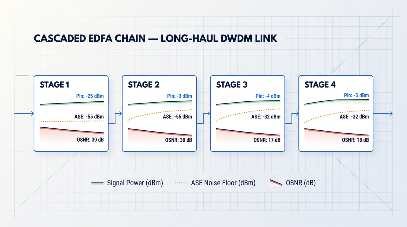
In a single amplifier, ASE is manageable. In a cascaded amplifier chain — the architecture of any long-haul DWDM link — ASE accumulates with each stage and sets a hard limit on the OSNR available at the receiver.
ASE is therefore not simply a known nuisance to be accepted; it is a design discipline. Optical isolators suppress backward-propagating ASE. Optical bandpass filters reject out-of-band ASE power. EDF length optimisation balances gain against ASE generation. System architecture — including amplifier spacing and span loss targets — determines how quickly ASE accumulates across the link.
Noise Figure: Quantifying ASE Impact
Noise figure (NF) is the metric that quantifies how much an EDFA degrades the signal-to-noise ratio of the optical signal passing through it. In practical terms, it measures how much ASE the amplifier adds relative to the gain it provides.
The quantum limit for an ideal EDFA — one operating with complete population inversion — is 3 dB. This is a fundamental physical lower bound rooted in quantum noise; no EDFA design can beat it, regardless of how the architecture is optimised.
Practical devices do not reach this limit. The gap between the quantum floor and real-world performance is driven primarily by inversion completeness, and this is where the pump wavelength choice — covered in the erbium physics section — has direct performance consequences.
At 980 nm, pump photons excite erbium ions to the ⁴I₁₁/₂ level, which lies well above the gain band. The resulting population inversion is clean and nearly complete, producing lower spontaneous emission rates and therefore a lower noise figure. At 1480 nm, the pump wavelength overlaps directly with the gain band, which means stimulated emission occurs in the pump direction, preventing full inversion and adding more ASE to the output.
This is why 980 nm pumping is the preferred architecture wherever low noise figure is the priority — the physics of the pump transition produce a fundamentally cleaner inversion than 1480 nm can achieve, and that difference appears directly in the NF specification.
In a cascaded EDFA chain, the noise figure of the first amplifier has the greatest impact on overall system OSNR. Noise added at the first stage is amplified by every subsequent stage — a 1 dB improvement in the first amplifier's NF can outweigh optimising every amplifier that follows it.
Because NF at the first amplifier stage dominates the system noise budget, the choice of pump wavelength, inversion level, and EDF design at that position carries disproportionate weight in the overall link design.
Gain Saturation and Cross-Gain Effects
As input signal power increases, the stimulated emission rate accelerates — and the population inversion that sustains gain is progressively depleted by the signal itself. When inversion drops below the level needed to maintain small-signal gain, gain compression sets in and output power approaches a ceiling: the saturated output power.
The saturated output power is not a fixed property of EDFA technology. It depends on pump power, EDF design, and operating conditions — all of which are engineering choices that can be tuned to meet a given system requirement.
In a single-channel system, saturation is a straightforward trade-off between input power and gain. In a multi-channel WDM system, the situation is more complex and more consequential.
A strong channel carrying high input power can deplete a disproportionate share of the available population inversion, compressing the gain seen by weaker channels sharing the same EDF. This is cross-gain saturation — a channel-interaction effect with no analogue in single-channel operation, and one that directly degrades OSNR balance across the WDM comb.
Cross-gain saturation becomes particularly acute when channel loading changes dynamically — for example, when channels are added or dropped in a reconfigurable network — because the inversion level, and therefore the gain experienced by all remaining channels, shifts with the aggregate input power.
With these performance characteristics understood as engineering outcomes rather than fixed properties, the distinction between EDFA types becomes meaningful in a new way: booster, in-line, and pre-amplifier configurations each prioritise a different subset of these metrics, driven by where in the optical link they sit and what the system demands of them at that position.
See the Specs Behind the Theory
Now that gain, noise figure, and saturation make sense on paper, see how those metrics translate into real custom EDFA hardware — built to your application's requirements.
EDFA Types: Booster, In-Line, and Pre-Amplifier Explained
A single EDFA design cannot be optimised for every position in a transmission link simultaneously — the signal conditions at the transmit end, the mid-span, and the receive end are fundamentally different, and each imposes a different engineering priority on the amplifier placed there.
The booster amplifier sits immediately after the transmitter or DWDM multiplexer, at the launch point of the link, where the signal is fresh and the signal-to-noise ratio is at its highest.
At this position, the primary design priority is maximum output power: the booster must launch a strong signal into the first fibre span to give the link the best possible margin for the spans ahead.
Noise figure is a secondary concern here — because the SNR is already high, even a somewhat elevated noise contribution from the booster is diluted by the signal power rather than compounding it, leaving the final OSNR at the receiver largely unaffected.
The in-line amplifier operates at intermediate points along the transmission link, typically spaced every 80–100 km to compensate for the cumulative attenuation of each fibre span — standard single-mode fibre attenuates at roughly 0.2 dB/km in the C-band, meaning an 80 km span introduces approximately 16 dB of loss.
This is the most demanding position of the three: the signal arrives weakened and carrying accumulated noise from every preceding amplifier stage, so the in-line amplifier must deliver high gain, high output power, and a low noise figure simultaneously.
Because in-line amplifiers appear multiple times within a single link, their noise contributions compound through the cascade — each stage's ASE noise accumulates on top of the last, progressively degrading the OSNR that reaches the receiver.
The pre-amplifier is placed at the receiving end of the link, immediately before the photodetector or DWDM demultiplexer, where the signal arrives at its weakest after traversing the full transmission distance.
Its primary design priority is the lowest achievable noise figure — typically 4–5 dB — because at this position, noise figure is the last engineering lever available before the signal is committed to the detector; any noise added here cannot be corrected downstream.
Moderate gain and output power are sufficient for the pre-amplifier: it does not need to drive a fibre span, only to bring the signal up to the level required by the photodetector.
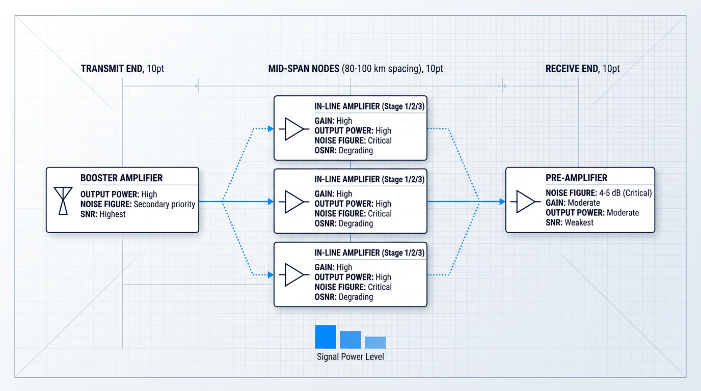
Link budget analysis is the engineering discipline that governs where each type goes, how many in-line stages the link requires, and what gain and noise figure targets each stage must meet to deliver an acceptable OSNR at the receiver.
A fundamental principle of cascaded noise analysis — formalised in the Friis formula — is that the noise contribution of each successive amplifier stage is divided by the cumulative gain of all preceding stages, making the first stage in any chain the dominant contributor to overall system noise.
For the pre-amplifier, this means it functions as the first amplifier seen by the receiver: any noise it adds arrives at the detector at full weight, with no subsequent gain stage to dilute it — which is precisely why its noise figure specification is so critical.
The Friis cascade principle means that noise figure matters most where gain cannot dilute it: at the pre-amplifier (last stage before detection) and at every in-line stage that repeats across the link. A booster amplifier with a slightly elevated noise figure has negligible impact on final OSNR; the same noise figure on a pre-amplifier or a poorly specified in-line chain can make the link unworkable.
By combining a booster amplifier at the transmit end, cascaded in-line amplifiers at 80–100 km intervals, and a pre-amplifier at the receive end, point-to-point reach can extend to 400 km and beyond without optical-electrical-optical regeneration.
With forward error correction and sufficient cascaded in-line stages, transmission distances can exceed 1,000 km — demonstrated in DWDM systems using 19 in-line EDFAs to carry 400 Gbps over 1,500 km using soft-decision FEC.
With the three-type architecture in place, the engineering focus shifts from static placement to dynamic operation: in a live DWDM network, channels are added and dropped continuously, creating power excursions that propagate through the amplifier cascade — and the control modes that govern how EDFAs respond to those transients are the subject of the next section.
Control Modes and Power Transients in Live DWDM Networks
A live DWDM network is nothing like the controlled environment of a lab bench characterisation. Channels are provisioned, rerouted, and dropped dynamically — and every change in channel loading shifts the total input power seen by every downstream EDFA in the chain.
Without active control, a shift in input power causes the amplifier's gain and output power to drift, and that drift propagates through each subsequent stage. The question for any real deployment is not whether the amplifier chain responds to these events, but whether it responds in a controlled, predictable way — or whether surviving channels experience damaging power excursions that degrade signal quality.
EDFA Control Modes: AGC, APC, and ACC
Three operating modes address this dynamic control problem, each holding a different parameter constant and accepting a different trade-off in return. Choosing between them is one of the fundamental design decisions for any DWDM deployment.
| Control Mode | Parameter Held Constant | What Varies | Typical Application |
|---|---|---|---|
| Automatic Gain Control (AGC) | Total mean gain (input-to-output power ratio) | Output power; per-channel gain across WDM spectrum | In-line amplifiers in cascaded DWDM spans |
| Automatic Power Control (APC) | Total output power | Gain; per-channel power changes if channel count changes | Fixed launch power into next fibre span; linear regime compliance |
| Automatic Current Control (ACC) | Pump laser drive current | Gain and output power both free to vary with input changes | Point-to-point links with stable, predictable channel loading |
Comparison of EDFA control modes across what is held constant, what varies, and typical application context
AGC is the most common operating mode for in-line amplifiers: it continuously monitors input and output power, then adjusts pump laser current to maintain a constant target gain regardless of how total input power fluctuates.
Its critical limitation, however, is that it maintains total mean gain — not per-channel gain. Because the erbium emission cross-section varies across the C-band, the gain spectrum is not flat, and when channel loading changes, AGC's response to the shift in mean gain causes wavelength-dependent power redistribution among surviving channels: a newly added high-gain channel effectively steals power from lower-gain channels, while adding a low-gain channel feeds power to higher-gain ones.
APC maintains a fixed total output power by adjusting pump current to compensate for input variations — the right choice when a specific launch power into the next span is required to keep the link within its linear operating regime or to meet a defined budget target. The trade-off is that if channel count changes, APC holds total power constant while allowing per-channel power to shift proportionally.
ACC holds the pump laser drive current fixed, letting both gain and output power vary freely with input signal changes. It is the simplest mode and suits applications where input conditions are stable and predictable, and where the consistency of a fixed pump operating point is valued over dynamic compensation.
Power Transients in DWDM Networks
Even a well-designed AGC loop cannot fully prevent power transients — and understanding why requires looking at the physics. When a channel is added or dropped, total input power changes abruptly, which immediately perturbs the rate of stimulated emission in the erbium-doped fibre and, in turn, disturbs the population inversion.
The timescale over which this perturbation plays out is set by the erbium upper-state lifetime: gain changes in EDFAs occur on the order of tens of microseconds. A feedback-based AGC loop responds to a deviation it detects at the output — but the gain excursion is already underway before the correction arrives, meaning no finite-speed control loop can fully suppress the initial transient.
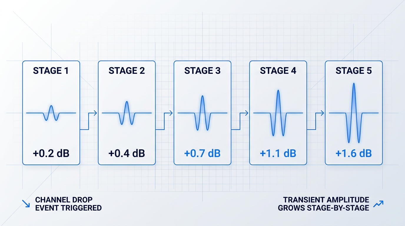
The consequences become more serious in a cascaded chain. Each amplifier responds to the perturbed output of the one before it, so the excursion amplitude accumulates stage by stage. Research has shown that power fluctuations in surviving channels should be limited to approximately 1 dB to protect channel quality, which implies EDFA control loop response times in the range of 100–200 ns.
Excursions of up to 2 dB in surviving channel power have been demonstrated experimentally in as few as three cascaded AGC-controlled EDFAs following haphazard channel additions — well above the 1 dB industry threshold for acceptable power fluctuation.
The diagram below illustrates how a channel drop event triggers a transient excursion in surviving channel power, and how that excursion amplitude grows as it propagates through successive amplifier stages in a cascaded chain.
Suppressing these transients requires engineering at multiple points in the system, and the most effective deployments treat the available mitigation techniques as complementary tools rather than alternatives.
- Feed-forward pump control: Monitors input power directly and proactively adjusts pump current before the output excursion propagates — faster than feedback-only AGC because it acts on the cause, not the effect.
- High-speed VOA suppression: A VOA with sub-microsecond response (Fujikura demonstrated response times below 1 µs) attenuates residual transients that feed-forward alone cannot suppress, cutting Drop-event settling time by up to 98%.
- Gradual channel power ramp: Rather than adding a channel at full power instantaneously, ramping power up gradually reduces the amplitude and duration of the transient seen by the amplifier chain.
Fujikura's combined feed-forward plus high-speed VOA approach demonstrated gain excursions below 0.8 dB with settling times under 3 µs for Add events, and below 1.2 dB with settling times under 20 µs for Drop events — both within the 1 dB industry threshold when the full control architecture is engaged.
The asymmetry between Add and Drop performance is physically meaningful: during a Drop event, both input signal intensity and pump intensity at the EDF decrease, which lengthens the effective upper-state lifetime and slows the population inversion's recovery — a dynamic that feed-forward control alone cannot compensate, and where a fast VOA delivers its greatest benefit.
Controlling transients and selecting the right operating mode address the dynamic operational challenges internal to the amplifier itself; the next consideration shifts to how EDFAs integrate with the surrounding physical system — including the practical assembly challenges that arise when joining components with differing mode field diameters and managing the splice losses that accumulate in a real amplifier chain.
EDFA Integration and Amplifier Technology Comparison
Understanding the EDFA working principle on paper is one thing; deploying an amplifier that actually performs to its datasheet specification is another discipline entirely. The gap between a well-designed EDFA and one that delivers its designed gain and noise figure in the field comes down to physical realities that no energy-level diagram captures: the quality of every splice, the geometry of every fibre interface, and the behaviour of every surrounding component.
Practical Integration Challenges
The most consequential integration issue is mode field diameter (MFD) mismatch at the junction between erbium-doped fibre and standard single-mode fibre.
EDF is designed with a small core and a high core-cladding refractive index difference to maximise pump intensity across the erbium ion population — a geometry that inherently produces a smaller MFD than the 8–10 µm typical of standard SMF.
When EDF is spliced to SMF, this geometric mismatch causes coupling loss at the splice point even when the splice itself is mechanically perfect: the two mode fields simply do not overlap completely, and optical power is lost to radiation.
In practical terms, MFD mismatch means that less pump power reaches the erbium ions than the design assumes — which, as established when examining performance characteristics, directly reduces the inversion level and therefore the achievable gain.
Beyond MFD mismatch, splice losses from poor cleave angles, core offset, or contamination compound the problem by further reducing the pump power delivered to the EDF.
Each additional tenth of a decibel of splice loss shifts the amplifier away from its optimum operating point — the inversion level at which gain and noise figure are simultaneously at their design values — and the effect accumulates across every splice in the signal and pump paths.
Well-prepared fused splices in standard fibre typically achieve losses between 0.01 and 0.1 dB; at the EDF-to-SMF interface, achieving the lower end of that range requires careful attention to cleave quality and fusion parameters optimised for the mismatched fibre geometries.
On polarisation effects, the EDFA itself is well-behaved: polarisation-dependent gain (PDG) in a well-designed EDFA is typically below 0.1 dB, making it essentially polarisation-insensitive from a gain perspective.
However, polarisation-dependent loss (PDL) in the surrounding signal-path components — isolators, WDM couplers, connectors — can interact with even small PDG values to produce signal quality variation across the system as a whole, so the system context around the EDFA warrants careful attention even when the amplifier itself is well-behaved.
Pump leakage at the amplifier output is a separate concern: residual pump light at 980 nm or 1480 nm that reaches the signal output can interfere with downstream components, and managing it requires appropriate WDM coupler design and correct placement of the output isolator to block any pump that passes through the gain fibre.
These integration considerations — MFD mismatch, splice quality, and system-level polarisation management — represent the layer of practical knowledge that sits on top of theoretical design, and they are what distinguishes a commissioned system from a paper specification.
EDFA vs. Raman and Semiconductor Optical Amplifiers
Situating EDFA within the broader amplifier landscape clarifies not just why it dominates long-haul networks, but where its boundaries lie and how other technologies complement rather than simply compete with it.
Raman amplifiers operate on a fundamentally different physical mechanism: stimulated Raman scattering, in which high-power pump photons transfer energy to signal photons via the vibrational modes of the silica glass lattice, with the pump wavelength chosen to be approximately 100 nm shorter than the target signal wavelength.
Because Raman scattering occurs in the transmission fibre itself, distributed Raman amplification keeps average signal power lower along the span, which reduces nonlinear impairments and improves OSNR — an advantage that becomes decisive over very long distances where EDFA-only chains accumulate noise at each lumped amplifier site.
Raman gain is also wavelength-agnostic: by selecting the pump wavelength, gain can be directed into the S-band (1460–1530 nm) where erbium ions produce little useful emission, making Raman the primary tool for extending amplification beyond the C- and L-band windows.
In modern long-haul networks, Raman and EDFA are frequently deployed together rather than as alternatives: distributed Raman provides low-noise gain along the span, while EDFA provides high-efficiency lumped gain at amplifier sites, with the hybrid combination achieving OSNR performance that neither technology reaches independently.
Semiconductor optical amplifiers (SOAs) take a different approach again: stimulated emission occurs in a forward-biased semiconductor p-n junction, making SOAs compact, electrically pumped, and manufacturable at low cost without any pump laser diode.
For long-haul WDM amplification, however, SOAs face three structural disadvantages relative to EDFA: noise figures typically in the range of 6–10 dB (compared to 4–6 dB for well-designed EDFAs), gain saturation occurring at relatively low optical power levels, and intrinsically polarisation-sensitive gain that requires additional design measures to mitigate.
The gain saturation issue is particularly significant in multi-channel WDM systems: because the SOA carrier lifetime is on the order of nanoseconds, gain responds rapidly to changes in signal power, causing cross-gain modulation between channels that degrades signal quality as channel count increases.
| Parameter | EDFA | Raman Amplifier | SOA |
|---|---|---|---|
| Amplification type | Lumped (discrete component) | Distributed (transmission fibre) or lumped | Lumped (semiconductor chip) |
| Gain range | 20–40 dB | ~10–15 dB per stage (distributed); up to ~30 dB discrete | Up to ~30 dB |
| Noise figure | 4–6 dB (practical); 3 dB theoretical minimum | Can be sub-3 dB or even negative (distributed, equivalent lumped NF) | 6–10 dB (typical) |
| Wavelength coverage | C-band (1530–1565 nm); L-band with design adjustment | Tunable — any band by pump wavelength selection; S-band capable | 850–1600 nm range depending on semiconductor material |
| Upper-state / carrier lifetime | ~8–10 ms (Er³⁺ metastable state) | ~3–6 fs (near-instantaneous Raman transition) | Nanoseconds (semiconductor carriers) |
| Primary application | Long-haul and metro DWDM in-line, booster, pre-amp | Ultra-long-haul OSNR enhancement; S-band coverage; hybrid with EDFA | Short-reach, metro, access networks; optical signal processing |
Side-by-side comparison of EDFA, Raman, and SOA across key quantitative performance axes to support the amplifier technology discussion.
The table makes the structural picture clear: EDFA occupies a performance tier that neither Raman nor SOA can replicate within the C-band at scale, while each technology holds genuine advantages in specific operating regimes.
The distributed Raman noise figure entry deserves particular attention — its sub-3 dB equivalent lumped noise figure is a mathematical consequence of the distributed gain geometry, not a violation of the 3 dB quantum limit, and it is what makes Raman so effective as a pre-amplification stage ahead of a lumped EDFA.
SOAs, despite their noise and saturation limitations in WDM contexts, retain clear advantages in compactness and electrical pumping for applications where those properties matter more than raw noise performance — metro access, short-reach links, and optical signal processing applications that deliberately exploit the fast gain dynamics.
EDFA's dominance in long-haul C-band transmission is mechanistically grounded: the Er³⁺ upper-state lifetime of ~8–10 ms is long enough that gain responds only to average signal power, not to individual channel fluctuations — suppressing cross-gain modulation across WDM channels in a way that SOAs (nanosecond carrier lifetime) cannot. Combined with 20–40 dB gain, 4–6 dB noise figures, and natural alignment with silica fibre's lowest-attenuation window, no other single amplifier technology matches EDFA's performance profile at C-band scale.
With both the physical integration realities and the broader amplifier landscape now in view, the guide's full arc — from quantum mechanics and erbium energy levels through to assembly, commissioning, and technology choice — is complete.
The concluding section draws those threads together into a unified picture of what it means to understand, specify, and deploy an erbium-doped fibre amplifier in a real optical network.
Ready to Put the Theory Into Practice?
EDFA performance is shaped by every engineering decision in the chain. Talk to our specialists about custom amplifier design and real-world implementation for your specific application.

Conclusion
Putting It All Together: From Physics to Practice
What this guide has traced, from the quantum transitions inside an erbium ion through to splice tolerances in a deployed chassis, is that EDFA performance is an engineering outcome — shaped at every level by deliberate decisions, not delivered as a fixed property of the technology.
That understanding is what makes the physics worth knowing: it turns datasheet numbers into variables you can reason about, and gives you the foundation to work confidently through link budgets, amplifier type selection, and the gain dynamics of cascaded systems.
Frequently Asked Questions About EDFA Working Principles
Answers to the most common questions about how erbium-doped fibre amplifiers work — covering the underlying mechanism, key performance parameters, and how EDFAs function within DWDM long-haul networks.
ASE noise originates when excited Er³⁺ ions in the metastable ⁴I₁₃/₂ state decay spontaneously rather than through stimulated emission, releasing photons of random phase and direction. These photons are then amplified along the same erbium-doped fibre path as the signal, producing broadband noise that accumulates across cascaded amplifier chains and degrades optical signal-to-noise ratio (OSNR). Management relies on four principal approaches: optical isolators prevent ASE from feeding back into the gain medium; optimising EDF length avoids excess spontaneous emission from fibre that is longer than the signal requires; pump power control maintains inversion at the level needed for gain without generating unnecessary spontaneous emission; and optical bandpass filtering at the output limits the spectral width of ASE propagating to the next amplifier stage.
In forward (co-propagating) pumping, the pump laser travels in the same direction as the signal through the erbium-doped fibre. The signal enters a region of high population inversion at the input end, where the noise contribution from spontaneous emission is smallest — giving this configuration the lowest achievable noise figure. In backward (counter-propagating) pumping, the pump travels in the opposite direction. Inversion is highest at the output end where the signal is strongest, yielding higher saturated output power. Bi-directional pumping combines both pump lasers simultaneously, maximising gain and output power at the cost of added complexity. The practical implication: forward pumping suits pre-amplifiers where noise figure is paramount; backward pumping is the standard choice for booster amplifiers where output power is the priority.
A pump laser at 980 nm or 1480 nm excites Er³⁺ ions in a short length of erbium-doped silica fibre into the metastable ⁴I₁₃/₂ energy level, creating population inversion. Incoming signal photons at approximately 1550 nm then trigger stimulated emission: each excited ion releases an additional photon at the same wavelength, phase, and direction, amplifying the signal entirely within the optical domain — no electrical conversion required. A WDM coupler combines the pump and signal wavelengths before they enter the doped fibre; optical isolators at the input and output suppress back-reflections. The result is substantial gain across the C-band, making EDFA the standard amplification technology for long-haul optical networks.
A single-stage EDFA typically delivers small-signal gain of 20–40 dB, with saturated output power reaching +17 dBm or higher in production devices and high-power designs exceeding +23 dBm. The gain achieved in any specific device depends on three variables: pump power (which sets the population inversion level), EDF length (which determines how much gain medium the signal traverses), and input signal power (higher input drives the amplifier toward saturation, compressing gain). Gain also varies spectrally across the C-band due to the shape of erbium's emission cross-section — gain flatness is a deliberate design outcome achieved through gain-flattening filters, not an inherent property of the amplifier.
In a dense wavelength-division multiplexing (DWDM) system, an EDFA is the optical amplifier that simultaneously boosts all WDM channels in a single pass through the erbium-doped fibre. Its gain window spans the C-band (approximately 1530–1565 nm), which covers the full channel grid used in DWDM long-haul networks. Before EDFA, long-haul networks required optical-electrical-optical (OEO) regenerators at every span — a costly, wavelength-specific process that could not scale to multi-channel WDM. EDFA eliminated that bottleneck by amplifying all channels simultaneously in the optical domain, enabling the growth of long-haul DWDM capacity. One important caveat: gain flatness across the C-band is not automatic, and gain-flattening filters are required to ensure all channels receive equal amplification.
EDFA dominates long-haul optical networks because its C-band gain window aligns precisely with silica fibre's lowest-attenuation transmission window, it delivers high gain with low noise figures, and its long erbium upper-state lifetime suppresses cross-gain modulation between WDM channels — a significant advantage in multi-channel systems. Raman amplifiers use stimulated Raman scattering distributed along the transmission fibre itself; they can be tuned to amplify at virtually any wavelength and are frequently deployed alongside EDFAs in ultra-long-haul systems to improve OSNR through distributed gain. Semiconductor optical amplifiers (SOAs) are compact and electrically pumped, but suffer from higher noise figures, lower saturation power, and polarisation-dependent gain, making them less suited to multi-channel long-haul amplification. In practice, EDFA and Raman are often used together rather than as mutually exclusive alternatives.