

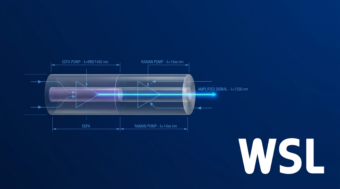
Introduction
If you're weighing up EDFA against a Raman amplifier for a real deployment, you already know the basics — both technologies compensate for fibre loss, and both have a place in modern optical networks.
What this guide works through is the decision itself: how each technology actually behaves, where each one excels, and how to match the right choice to your specific application — including the cases where using both together is the answer.
The goal is a clear, evidence-based recommendation, not a generic pros-and-cons list.
TL;DR
Neither EDFA nor Raman is universally superior — the right choice is determined by your deployment context. The physics and engineering trade-offs that separate these two technologies are precisely what make one a better fit than the other for a given span, application, or budget. Understanding those trade-offs is what turns a difficult decision into a confident one.
This article covers:

How EDFA and Raman amplifiers physically work
Gain, bandwidth, and noise figure compared
Pump laser requirements and operational complexity
Deployment contexts and application fit for each
When hybrid EDFA-Raman configurations make sense
EDFA vs Raman Amplifier: Understanding the Fundamentals
Every optical signal launched into a fibre span begins losing power immediately. Signal attenuation is an inescapable physical reality of fibre transmission — silica glass absorbs and scatters light continuously, and without intervention, even the lowest-loss modern fibre will reduce a signal to noise within a few hundred kilometres.
The traditional answer was the OEO regenerator: a device that converts the optical signal to electrical, cleans and retimes it, then retransmits it as light. OEO regeneration works, but it is expensive, requires one unit per wavelength, and is inherently rate- and format-specific — a significant constraint in DWDM systems carrying dozens of channels simultaneously.
Optical amplification solved this by boosting signals entirely within the optical domain, with no electrical conversion. A single broadband amplifier can restore all wavelengths in a WDM system at once, independent of data rate or modulation format — a capability that made continental and transoceanic fibre networks economically viable and technically scalable.
Lumped vs Distributed Amplification
Not all optical amplifiers work the same way architecturally, and this distinction matters more than any other concept in the EDFA vs Raman amplifier comparison. The fundamental divide is between lumped amplification and distributed amplification.
In a lumped (discrete) architecture, gain is concentrated at fixed points along the link — typically at the end of each fibre span. Signal power falls progressively across the span, reaching its minimum just before the amplifier node, where it is restored in a single discrete step.
In a distributed architecture, gain occurs continuously along the transmission fibre itself, spread across the span rather than concentrated at one point. Because the signal is being amplified as it travels, it never drops as far before recovery begins — which fundamentally changes how noise accumulates along the link.
Whether gain is concentrated at discrete span endpoints (lumped) or spread continuously along the transmission fibre (distributed) is not a minor technical detail — it is the architectural choice that determines noise accumulation behaviour across the entire link, and the primary lens through which EDFA and Raman amplifiers differ.
EDFA (erbium-doped fibre amplifier) is the canonical lumped amplifier. It uses a short length of erbium-doped silica fibre as its gain medium and has dominated C-band and L-band long-haul and metro networks for three decades — the established, widely-deployed baseline against which Raman is evaluated.
The Raman amplifier takes the opposite architectural approach: it exploits stimulated Raman scattering within the transmission fibre itself to provide distributed gain along the span. Unlike EDFA, it is not confined to specific wavelength bands — the gain window is set by pump wavelength choice, making it applicable across a broad spectral range.
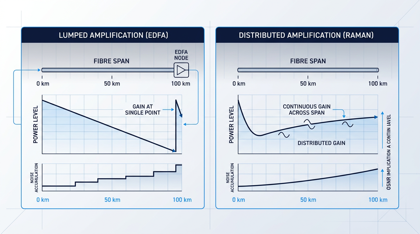
The metric that makes this architectural distinction consequential in practice is OSNR — optical signal-to-noise ratio. In a cascaded amplifier chain, noise accumulates with every amplifier stage, and it is this accumulated noise — not raw gain — that ultimately limits link capacity and reach.
Because noise accumulates additively across cascaded amplifiers, the amplifier technology that better preserves OSNR for a given deployment scenario is the better engineering choice — regardless of which delivers higher peak gain. OSNR is therefore the governing system metric throughout this guide.
This guide compares EDFA and Raman amplifier technologies across working principles, performance parameters, and deployment contexts. Other amplifier types — including semiconductor optical amplifiers (SOAs) and thulium-doped fibre amplifiers (TDFAs) — are out of scope; this is not a general survey, nor a product or vendor catalogue.
With the architectural context established, the guide now examines each technology's working principles in depth — beginning with EDFA, the lumped amplifier that has defined long-haul optical networking for over three decades.
How EDFA Works: Stimulated Emission Explained
EDFA's dominance in long-haul networking is no accident. A set of physical properties in erbium-doped silica fibre aligns almost perfectly with the requirements of DWDM transmission — from its emission wavelength to its gain dynamics — and understanding those properties is the foundation for every comparison that follows.
The Gain Medium: Erbium-Doped Silica Fibre
An EDFA is not an electronic component; it is a specialised piece of optical fibre — a short length of silica glass whose core has been doped with trivalent erbium ions (Er³⁺).
Practical erbium-doped fibre lengths vary with design objectives, but C-band configurations typically use fibre in the range of roughly 10 to 30 metres, with many optimised designs clustering between 14 and 22 metres depending on pump power and target gain.
This short active section is where all the gain occurs — consistent with the lumped amplifier architecture established in the previous section, where gain is concentrated at a discrete point rather than distributed across the transmission span.
Population Inversion and Stimulated Emission
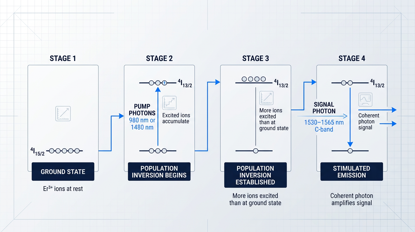
A pump laser injects light into the doped fibre, exciting Er³⁺ ions from the ground state (⁴I₁₅/₂) up through a short-lived intermediate level and into the metastable ⁴I₁₃/₂ excited state, where they accumulate.
When more ions occupy the excited state than the ground state, population inversion is established — the prerequisite for optical gain.
Signal photons passing through the doped fibre then trigger stimulated emission: each excited ion is induced to drop to the ground state, releasing a photon that is coherent with the signal — identical in wavelength, phase, and direction — producing net amplification.
The C-Band Emission Window
Stimulated emission in erbium-doped silica fibre occurs in the C-band, spanning approximately 1530–1565 nm — precisely the lowest-attenuation transmission window of standard silica fibre.
This coincidence of gain spectrum and fibre transmission window is what made EDFA the dominant amplifier technology; no other practical gain medium offered the same alignment.
Coverage can be extended into the L-band (1565–1625 nm) by adjusting the inversion level — typically by using a longer erbium-doped fibre to reduce average inversion — enabling amplification across a combined bandwidth exceeding 80 nm in parallel C+L configurations.
Pump Wavelength Options: 980 nm vs 1480 nm
Two pump wavelength options are used in practice, each with distinct engineering trade-offs that suit different amplifier roles.
- 980 nm pumping: Achieves near-complete population inversion, yielding a lower noise figure. Preferred for preamplifiers and low-noise applications where OSNR is the critical constraint.
- 1480 nm pumping: Drives transitions directly into the gain level, giving higher quantum efficiency — more pump photons per watt. Preferred for power amplifiers where output power matters more than noise.
The gain efficiency difference is measurable: at a signal wavelength of 1533 nm, 980 nm pumping has demonstrated maximum gain efficiency of approximately 11 dB/mW, compared to around 6.3 dB/mW for 1480 nm pumping — reflecting the cleaner inversion achieved at the shorter pump wavelength.
Neither option is universally superior; the right choice depends on where in the amplifier chain the device sits and whether noise figure or output power is the binding constraint.
The Upper-State Lifetime and WDM Compatibility
The ⁴I₁₃/₂ metastable level has an unusually long upper-state lifetime of approximately 10 ms — a measured fluorescence decay time confirmed across erbium-doped silica fibre samples under standard conditions.
This slow response time is, counterintuitively, a critical system-level advantage: because the gain medium cannot respond to fluctuations occurring on nanosecond-to-picosecond timescales, power variations in one WDM channel cannot modulate the gain experienced by adjacent channels.
The ~10 ms upper-state lifetime means EDFA gain dynamics are orders of magnitude slower than WDM channel data rates. This inherently suppresses inter-channel crosstalk without any additional filtering — a property that no electronic equaliser can replicate at the same cost and simplicity, and a core reason EDFA became the default amplifier for DWDM long-haul systems.
Lumped Gain Architecture and ASE Noise
Because all gain is concentrated in the short doped fibre section, the signal reaches its lowest power level at the amplifier input — after traversing the full preceding span — before being restored to a high level at the output.
This is the fundamental architectural trade-off of lumped amplification: the signal is most vulnerable to noise precisely at the point where amplification begins, and any noise added there is carried forward with the amplified signal.
The dominant noise mechanism is amplified spontaneous emission (ASE): Er³⁺ ions occasionally emit photons spontaneously without a triggering signal photon, and those photons are amplified along with the signal, accumulating as broadband noise across the gain bandwidth.
ASE sets the fundamental noise floor of an EDFA link and is the primary driver of optical signal-to-noise ratio (OSNR) degradation in cascaded amplifier chains — a topic developed further in the noise and OSNR comparison section.
EDFA Headline Performance Parameters
These are the established baseline figures for EDFA performance that the comparison sections will build on.
| Parameter | Typical Value | Notes |
|---|---|---|
| Small-signal gain range | 20–40 dB | Standard single-stage configurations; booster designs can exceed this range |
| Noise figure (ideal) | 3 dB | Quantum limit; approached with 980 nm pumping and optimised design |
| Noise figure (commercial) | 4–6 dB | Typical practical devices; UCSB lecture data cites 4–5 dB as common |
| C-band gain bandwidth | ~35 nm (1530–1565 nm) | Determined by Er³⁺ emission spectrum in silica glass host |
| L-band extension | 1565–1625 nm | Achievable with longer EDF and reduced inversion level |
Establishes the quantitative baseline for EDFA performance parameters — gain range, noise figure, and gain bandwidth — that subsequent comparison sections reference directly.
The 3 dB quantum limit on noise figure is a hard physical floor, not a vendor specification — it reflects the minimum noise penalty imposed by the amplification process itself, and even the best-designed EDFAs operate slightly above it in practice.
The ~35 nm C-band gain bandwidth is sufficient to simultaneously amplify dozens of DWDM channels, though the gain is not uniform across this window — gain flatness management is a separate design consideration addressed in the gain and bandwidth section.
With those parameters established, the next section examines Raman amplification — a fundamentally different architecture that distributes gain along the transmission fibre itself rather than concentrating it in a short doped section.
How Raman Amplifiers Work: Stimulated Raman Scattering
With EDFA, the gain medium is a dedicated spool of erbium-doped fibre housed in a rack unit at the amplifier site. With a Raman amplifier, the gain medium is the transmission fibre itself — the same fibre already carrying the signal across the span.
This is not a minor implementation detail. It represents a fundamentally different architectural philosophy, and every performance difference between the two technologies flows from it.
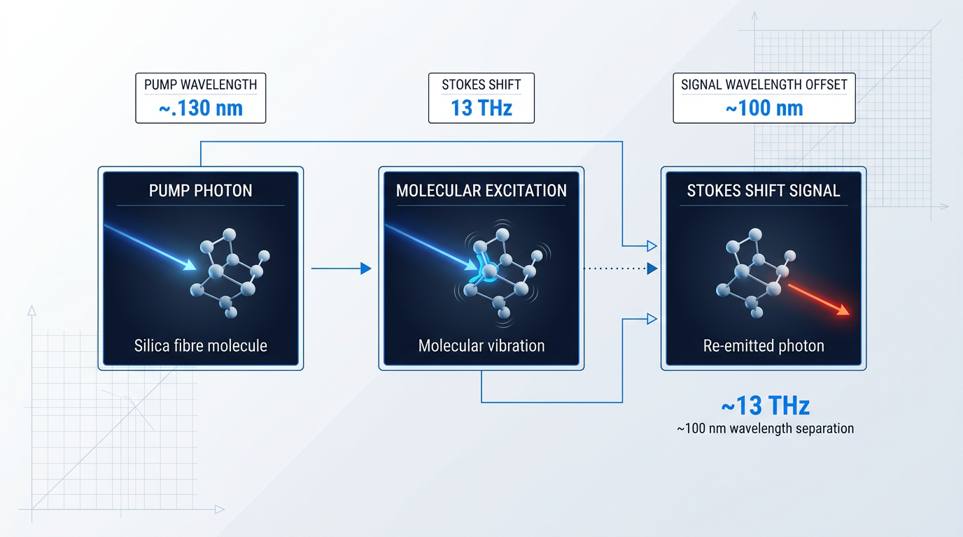
The underlying physics is stimulated Raman scattering (SRS) — a nonlinear interaction between high-power pump photons and the silica molecules of the fibre. When a pump photon collides with a silica molecule, it excites a molecular vibration and re-emits a photon at a lower frequency, transferring the energy difference to the signal field. The frequency offset between pump and signal is the Stokes shift, which in silica fibre sits at approximately 13 THz — corresponding to roughly 100 nm of wavelength separation in the telecom window.
Distributed Amplification: The Fibre as Gain Medium
In an EDFA, gain is lumped: it occurs at a single, discrete point in the network, after the signal has traversed the full loss of the preceding span and arrived at the amplifier site in a heavily attenuated state.
In a distributed Raman amplifier (DRA), gain is spread continuously along the fibre span. Pump light is injected at the amplifier site and propagates back through the transmission fibre, providing gain to the signal throughout the span rather than only at its end.
The noise consequence of this distinction is significant. Because amplification is occurring throughout the span, the signal power never falls to the deeply attenuated level it would reach in a purely lumped system before gain is applied. The effective amplification point is much earlier in the span, where signal power is still relatively high — which means the signal-to-noise ratio at the point of gain is inherently better than in any lumped architecture.
In a distributed Raman amplifier, the transmission fibre simultaneously carries the signal and provides gain along the entire span. No other amplification technology achieves this — it is an architectural distinction, not just a performance parameter.
Pump Wavelength Flexibility and the Stokes Relationship
Because the Raman gain peak falls approximately 100 nm below the pump wavelength (the Stokes relationship), the amplified signal band is determined entirely by the pump wavelength selected — not by a fixed dopant emission spectrum.
This stands in direct contrast to EDFA, whose gain band is fixed by the erbium ion's emission spectrum to the C-band and, with appropriate fibre design, the L-band. A Raman amplifier can, in principle, amplify any signal band by choosing the appropriate pump wavelength — a flexibility that makes it relevant for signal bands EDFA cannot reach.
This flexibility comes at a cost: the Raman gain coefficient in silica fibre is substantially smaller than the stimulated emission cross-section in erbium. Achieving useful gain over practical fibre lengths requires pump powers in the range of hundreds of milliwatts to over 1 W — a non-trivial engineering and operational requirement that will be examined fully in the pump laser section.
Deployment Modes and Pump Configuration
Raman amplifiers are deployed in two distinct configurations, each with different implications for system architecture and performance.
- Distributed Raman Amplifier (DRA): Uses the existing transmission fibre as the gain medium. Pump light is injected at the amplifier site; no additional hardware enters the fibre path. Delivers the OSNR advantage of distributed gain.
- Lumped Raman Amplifier: Uses a dedicated spool of specialty fibre — typically highly nonlinear fibre with a small effective area — housed in a discrete unit, similar in form factor to an EDFA.
The DRA is the more architecturally distinctive of the two and the configuration that delivers the noise advantage described above. The lumped Raman amplifier is closer to EDFA in physical form, but it uses the Raman gain mechanism rather than stimulated emission — a different gain physics in a familiar package.
Within the DRA configuration, the pump can be directed either with the signal (co-propagating, or forward pumping) or against it (counter-propagating pumping, or backward pumping). Backward pumping is the standard deployed configuration for a practical reason: because pump and signal travel in opposite directions, pump power fluctuations are averaged out over the fibre propagation delay and do not couple directly into signal amplitude noise.
Forward pumping can offer a lower effective noise figure, since gain is applied earlier in the span when signal power is highest — but it introduces the risk of pump intensity noise transferring directly into the signal, a disadvantage that makes it uncommon in production systems.
Finally, multiple pump lasers at different wavelengths can be combined to tailor and flatten the Raman gain spectrum across a wide bandwidth. This multi-pump approach is what enables Raman to deliver broadband, spectrally flat gain — a capability that becomes particularly relevant when considering how Raman complements EDFA in hybrid architectures.
With the Raman mechanism and its architectural consequences established, the next step is to examine how these differences play out in the gain and bandwidth characteristics that matter most to network designers.
Gain and Bandwidth: How the Two Technologies Compare
Gain range and bandwidth are not abstract specifications — they determine whether a technology can actually serve a given deployment. A system that delivers 30 dB of gain in the wrong wavelength band, or achieves the right band with pump power that is impractical to supply, does not fit the requirement. Understanding how EDFA and Raman amplifiers differ across these two dimensions reveals something fundamental about each technology's character, not just its headline numbers.
Gain Range and Efficiency
EDFA delivers typical small-signal gains of 20–40 dB, with demonstrated gains exceeding 51 dB in research configurations, and it does so with remarkable pump efficiency: at 1533 nm, gain efficiencies as high as 11 dB/mW have been demonstrated with 980 nm pumping, and gains exceeding 30 dB can be produced by just a few milliwatts of pump power.
That efficiency advantage is rooted in the erbium ion itself — the stimulated emission cross-section in silica is large relative to the Raman gain coefficient, so each pump photon converts to signal gain more readily than in a Raman system.
Raman amplifiers face a fundamentally different challenge: the Raman gain coefficient in silica is intrinsically limited to approximately 1.21×10⁻¹¹ cm/W, which is considerably lower than that of erbium-doped fibre amplifiers. To achieve signal gains above 30 dB, Raman amplifiers require pump powers of several watts and fibre lengths spanning kilometres — a stark contrast to the milliwatt-scale pump requirements of EDFA.
In distributed configurations, the practical metric is on/off Raman gain: the ratio of received signal power with and without Raman pumping active. At pump powers around 300–700 mW, practical distributed Raman configurations achieve gains in the range of roughly 10–20 dB over a span, with one published result showing 31 dB at 600 mW using Truewave fibre and 46 dB at 700 mW — the latter representing an optimised configuration rather than a typical deployment baseline.
As pump power increases, Raman's total gain does scale — the relationship is approximately exponential with effective pump power — but so does the engineering complexity of managing pump depletion and nonlinear effects. The practical implication is that for equivalent gain figures, Raman requires substantially higher pump power than EDFA, which has direct consequences for pump laser selection and system cost (covered in detail in §8).
| Parameter | EDFA | Raman Amplifier |
|---|---|---|
| Typical gain range | 20–40 dB (small-signal); >50 dB demonstrated | 10–20 dB typical on/off gain (distributed); up to ~46 dB at high pump power |
| Gain efficiency | Up to 11 dB/mW at 980 nm pump; >30 dB gain from a few mW | ~1.21×10⁻¹¹ cm/W gain coefficient; watts of pump power needed for >30 dB |
| Amplification bandwidth | ~35 nm (C-band, 1530–1565 nm); L-band to ~1625 nm with separate stage | Determined by pump wavelength; 50–145 nm achievable with multi-pump configurations |
| Gain flatness approach | Gain flattening filter (GFF) required for DWDM; ±1 dB ripple typical across C-band | Engineerable via pump wavelength and power; ±0.2 dB achievable in two-pump C-band configurations |
| Gain saturation time constant | Milliseconds (erbium upper-state lifetime ~10 ms); transient effects on channel add/drop | Governed by pump depletion dynamics; instantaneous response to pump power variations |
Side-by-side comparison of EDFA and Raman amplifier gain and bandwidth parameters using sourced figures
The table makes the trade-off explicit: EDFA wins decisively on gain efficiency — more gain per milliwatt of pump power — while Raman's strength lies in bandwidth flexibility and gain profile engineering rather than raw conversion efficiency. For network designers, the gain efficiency gap means that EDFA remains the lower-cost, lower-complexity choice wherever the C-band or L-band covers the required channel plan.
Bandwidth: Fixed Spectrum vs Engineered Flexibility
EDFA's amplification window is set by the emission spectrum of the erbium ion in silica glass, which spans roughly 35 nm in the C-band (1530–1565 nm). This is not a design limitation that better engineering could overcome — it is a consequence of the Stark splitting of erbium's energy levels in the silica host, and it is fixed.
Extension to the L-band (1565–1625 nm) is achievable by operating the erbium-doped fibre at a lower inversion level — around 35–40% — typically using a separate amplifier stage or parallel configuration. Combining a C-band and L-band EDFA in parallel can yield a combined gain bandwidth exceeding 80 nm, though L-band EDFAs are less efficient because the operating wavelengths sit further from the 1530 nm emission peak.
For most deployed DWDM systems, the C-band constraint is not a practical limitation: the vast majority of commercial DWDM traffic operates within the C-band, and the available channel count within 35 nm at 50 GHz spacing already supports 80 or more channels. The constraint matters only when a network designer needs to reach bands that erbium simply cannot address.
Raman amplifiers have no such fixed constraint. Because the gain peak occurs at approximately 13 THz below the pump frequency — corresponding to roughly 100 nm at near-infrared wavelengths — the gain band simply shifts with the pump wavelength. Pumping in the 1460–1480 nm range yields Raman gain in the 1550–1600 nm band; choosing a different pump wavelength shifts the gain window accordingly, enabling amplification in the S-band, O-band, or any other transmission window.
This is an architectural distinction, not a minor feature. Raman is the only practical amplification technology capable of addressing bands that lie entirely outside the erbium emission spectrum — a capability that becomes decisive for ultra-wideband transmission systems requiring simultaneous amplification across multiple spectral windows.
With multi-pump Raman configurations — combining several pump lasers at different wavelengths and power levels simultaneously — the aggregate gain spectrum can be shaped and broadened to cover 50–145 nm of bandwidth in published demonstrations, with one recent result spanning 120 nm in a Raman-only configuration and 145 nm in a hybrid arrangement.
Unlike EDFA, whose gain window is fixed by the erbium ion's emission spectrum, Raman amplification can be positioned at any wavelength band simply by choosing the appropriate pump wavelength. This makes Raman the only viable amplification option for S-band, O-band, and other non-erbium windows — a distinction that shapes entire system architectures, not just individual component choices.
Gain Flatness in DWDM Systems
EDFA's gain spectrum across the C-band is not flat. There is a characteristic narrow peak around 1530 nm and a relatively flat shoulder region between roughly 1540 and 1560 nm, with the shape varying as a function of inversion level. In a multi-channel DWDM system, this non-uniformity means different channels receive different amounts of gain — and in a cascade of amplifiers, those differences accumulate: a gain ripple of 1 dB per amplifier can produce a 10 dB power differential across channels after ten cascaded stages.
The standard solution is a gain flattening filter (GFF) inserted within or after each EDFA, designed to impose a complementary loss profile that offsets the amplifier's gain shape. GFFs are well-established — implemented using thin-film filters, long-period fibre gratings, and other technologies — but they introduce insertion loss and add a component that must be matched to the specific amplifier's gain profile and operating conditions.
Raman's gain profile can be engineered to be inherently flatter over a target band by selecting pump wavelengths and power levels that produce a composite gain spectrum matching the channel plan. In two-pump C-band Raman configurations with automatic gain control, gain deviation can be held within ±0.2 dB — a level of flatness that EDFA with a passive GFF struggles to match across dynamic operating conditions. The trade-off is that achieving this requires careful pump engineering and active feedback control, adding system complexity that a passive GFF does not.
Gain saturation behaviour also differs in ways that matter for WDM operation. EDFA saturates with a time constant governed by the erbium upper-state lifetime of approximately 10 ms — slow enough that individual channel fluctuations do not modulate the gain seen by other channels in steady-state operation. However, when channels are added or dropped, the surviving channels can experience gain surges that propagate through a chain of amplifiers, with gain changes occurring on timescales of tens of microseconds; dynamic gain control or gain clamping is required to limit power fluctuations to acceptable levels.
Raman saturation is governed by pump depletion dynamics rather than an upper-state lifetime. Because the Raman gain responds essentially instantaneously to changes in pump power, pump intensity variations translate directly into gain variations — a behaviour that is qualitatively different from EDFA's slow saturation and has distinct implications for system stability and crosstalk management.
With gain and bandwidth characterised for both technologies, the next critical parameter is noise performance — specifically how each technology's noise figure and OSNR contribution shape the link budgets and transmission reach that ultimately determine system design.
Noise Figure and OSNR: What Actually Limits Your Link
Gain tells you how much the signal is boosted. Optical signal-to-noise ratio (OSNR) tells you how much noise has accumulated — and it is OSNR, not gain, that ultimately determines whether a long-haul link can close.
In a cascaded amplifier chain, each stage adds amplified spontaneous emission (ASE) noise, and the OSNR budget erodes with every span.
The engineering relationship is direct: reducing an amplifier's noise figure by 1 dB improves the system OSNR by 1 dB. That one-for-one relationship makes noise figure a first-order design parameter, not a secondary specification.
Every phase-insensitive optical amplifier is bounded by a theoretical minimum noise figure of 3 dB — the quantum limit, arising from unavoidable vacuum-field fluctuations at the amplifier input.
Commercial EDFAs approach but do not reach this limit. UCSB ECE228 lecture data confirms that 980 nm pumping, which drives near-complete population inversion, achieves a minimum noise figure below 4 dB, while 1480 nm pumping yields a minimum of 5.5 dB.
Across commercial EDFA designs, typical noise figures fall in the 4–5 dB range, with 1480 nm-pumped amplifiers sitting toward the upper end of that band.
In a multi-span long-haul system, OSNR at the link output degrades as accumulated ASE noise scales with the number of amplifier stages. As the ScienceDirect amplified-system analysis shows, system OSNR decreases by 10·log₁₀(N) for N cascaded spans — meaning noise figure is not just a per-amplifier concern but a system-level constraint that compounds with distance.
This is precisely where distributed Raman amplification offers a structurally different performance outcome, and the comparison table below captures the quantitative difference.
| Parameter | EDFA | Distributed Raman |
|---|---|---|
| Theoretical minimum NF (quantum limit) | 3 dB | Below 3 dB (sub-quantum-limit achievable) |
| Practical NF range (980 nm pump) | < 4 dB minimum; 4–5 dB typical | Not applicable — gain is distributed, not lumped |
| Practical NF range (1480 nm pump) | 5.5 dB minimum; higher in non-optimal configs | Not applicable |
| Effective NF in deployed systems | 4–5 dB typical (lumped, per span) | −2 to 0 dB (effective, per span) |
Quantitative comparison of EDFA and distributed Raman amplifier noise figure parameters, enabling direct evaluation of the OSNR performance gap between the two technologies.
The effective noise figure of −2 to 0 dB for distributed Raman — confirmed by the Cisco practical aspects document — represents a 5–6 dB advantage over a typical EDFA span. That margin translates directly into a larger link OSNR budget: more unregenerated span distance, or higher spectral efficiency at the same reach.
The physical reason for this advantage is not a measurement artefact — it is a genuine consequence of the distributed gain architecture.
In a lumped EDFA system, the signal propagates across the full span length losing power continuously, then is boosted at the span end. The amplifier operates on a signal that has already been maximally attenuated, amplifying it alongside all the ASE noise it generates.
In a distributed Raman system, gain is applied continuously along the transmission fibre itself, so the signal never drops to the floor it would reach in an unamplified span. The effective amplifier input is not the physical span end but a point within the fibre where the signal still carries meaningful power — raising the signal-to-noise ratio at the effective input and producing an effective noise figure that falls below the 3 dB quantum limit applicable to any lumped amplifier.
Distributed Raman's effective noise figure of −2 to 0 dB sits 5–6 dB below a typical EDFA — a margin that translates directly into longer unregenerated span distances or higher spectral efficiency at the same reach.
Raman Noise Penalties in Practice
Distributed Raman's effective noise figure advantage is real and significant, but the technology introduces three noise mechanisms that do not arise in EDFA systems and must be addressed in system design.
- Polarisation-Dependent Gain: Raman gain in silica is polarisation-selective: maximum when pump and signal polarisations align, near zero when orthogonal. Mitigated using depolarised or polarisation-multiplexed pump configurations.
- Pump RIN Transfer: In co-propagating configurations, pump power fluctuations couple directly to signal amplitude as relative intensity noise (RIN), degrading OSNR. Counter-propagating pumping averages out fluctuations over fibre transit time.
- Double Rayleigh Scattering: Signal photons backscattered twice by Rayleigh events are re-amplified and interfere with the forward signal as multipath interference (MPI). Accumulates across multi-span chains.
Each of these mechanisms has well-established mitigations that are standard in deployed systems. Polarisation-dependent gain is addressed by combining two pump lasers at orthogonal polarisation states, averaging out gain variation across the fibre.
Pump noise coupling is managed by adopting counter-propagating (backward) pumping as the default configuration: because pump and signal travel in opposite directions, pump power fluctuations are averaged over the full fibre propagation time rather than transferring directly to the signal — the primary engineering reason backward pumping is standard in deployed distributed Raman systems.
Double Rayleigh scattering is a design consideration for long multi-span chains but does not dominate system performance in well-engineered single-span configurations.
The OSNR advantage that distributed Raman delivers depends entirely on the high-power pump lasers that drive the distributed gain process — and those pumps carry real engineering and cost implications that the next section addresses.
Pump Laser Requirements: Power, Cost, and Complexity
Pump laser requirements are often treated as a procurement footnote in technology comparisons, but they are in practice an engineering and operational consideration that shapes system design, safety classification, fibre plant compatibility, and total cost of ownership — particularly in the EDFA vs Raman amplifier decision.
EDFAs are pumped by semiconductor diode lasers at one of two wavelengths: 980 nm or 1480 nm. These are distinct engineering choices with real trade-offs, not interchangeable options.
The 980 nm pump drives erbium ions through a three-level process that achieves near-complete population inversion, yielding a lower noise figure — forward pumping at 980 nm produces a noise figure of around 3.5 dB, compared to approximately 5.1 dB for forward pumping at 1480 nm, as documented in peer-reviewed EDFA modelling data. The 1480 nm pump, by contrast, offers higher power conversion efficiency — approaching 80% optical-to-optical conversion versus around 50% for 980 nm — making it the preferred choice for high-output-power booster stages where noise figure is secondary to raw output power.
In practice, high-performance EDFAs often combine both: a 980 nm pump at the input stage for low-noise pre-amplification, and 1480 nm pumping at the output stage for power. Typical pump power levels per stage are in the range of tens to a few hundred milliwatts — modest by optical standards.
Both 980 nm and 1480 nm pump laser markets are mature and competitive. These are commodity components with deep supply chains, long field deployment histories, and well-understood reliability profiles — pump laser cost is not a significant driver of EDFA system cost.
Raman Pump Requirements: Power, Complexity, and Cost
Raman amplification demands substantially higher pump powers. Diode-based distributed Raman systems typically operate with launch powers in the 500 mW to 1 W range per pump — and some configurations push considerably higher. Xtera field data from unrepeatered transmission experiments documents forward and backward distributed pump powers of 1,590 mW and 1,670 mW respectively on a single span.
The reason is fundamental, not incidental: the Raman gain coefficient in silica fibre is intrinsically small — on the order of 10⁻¹¹ cm/W — and Raman gain in dB scales linearly with pump power. Achieving useful gain over practical fibre lengths requires high pump powers as a direct consequence of this physical property, not because of any component limitation that better engineering could resolve.
Achieving a flat, broadband Raman gain profile across the C-band adds a further layer of complexity. A single pump produces a gain spectrum roughly 48 nm wide (FWHM ~6 THz) peaked at one offset frequency — insufficient for flat wideband amplification. Practical broadband Raman systems use multiple pump lasers at different wavelengths and powers, with the gain profiles superimposed and co-optimised. Cisco's production backward Raman pump modules, for example, use five pump wavelengths in the 1420–1500 nm range to deliver up to 1.9 W of distributed pump power, while co-propagating modules use three wavelengths. The complexity here is not simply component count — it is the system-level optimisation burden of achieving acceptable gain flatness across the target bandwidth, a process that is highly nonlinear due to pump-to-pump Raman interactions.
These high pump power levels introduce operational considerations that EDFA deployments do not face to the same degree. They are not reasons to avoid Raman, but they represent a discipline that Raman installations require and practitioners must plan for.
- Eye safety and laser classification: Watt-level Raman pump units are Class 4 laser products under IEC/EN 60825-1, requiring engineering controls, trained personnel and specific safety procedures at optical connectors.
- Connector cleanliness requirements: At watt-level pump powers, contaminated connectors or poor splices can trigger the fibre fuse effect — localised heating reaching 1,000°C to 5,000°C — capable of destroying kilometres of fibre in seconds. Cisco's Raman installation documentation enforces strict connector loss limits (as low as 0.2 dB for some fibre types) and specifies high-power connector types for all Raman pump ports.
- Fibre effective area compatibility: Raman gain efficiency is inversely proportional to fibre effective area (Aeff). Smaller Aeff fibres yield higher gain for a given pump power but also increase nonlinear penalties. Corning's fibre data shows an 80 µm² fibre delivers approximately 30% more Raman gain in dB than a 102 µm² fibre at the same pump power — so not all legacy fibre plants are equally suited, and fibre type assessment is a required pre-deployment step.
On cost, the contrast is clear. EDFA pump lasers at 980 nm and 1480 nm are commodity components; pump laser cost is not a meaningful driver of EDFA system cost. Raman pump modules are a different matter: the high-power 14xx nm pump sources used in Raman amplifiers are more specialised, and multi-pump configurations multiply that cost directly. Trade press reporting from Lightwave Online puts Raman pump subsystem costs at $20,000 to $60,000 per pump block — a figure that has historically been a significant barrier to widespread Raman adoption outside of long-haul and submarine applications where the OSNR benefit justifies the investment.
On reliability, both technologies perform well. Xtera's field data from deployed subsea systems shows that 14xx nm pump lasers exhibit exceptionally low failure-in-time rates — approximately 1 FIT for 1480 nm pumps — with no measurable degradation in pump performance or power consumption over the system lifetime. The 980 nm pumps used in EDFAs similarly achieve sub-100 FIT rates at several hundred milliwatts of output power. Reliability is not a meaningful differentiator between the two technologies at the pump laser level; the differentiation is cost and operational complexity.
The high pump power required by Raman amplification is a direct consequence of silica's intrinsically small Raman gain coefficient. It cannot be engineered away — only managed through system design choices such as fibre selection, multi-pump configuration, and span architecture.
With pump laser requirements fully characterised for both technologies, the next section consolidates all parameter-level findings — gain, noise figure, bandwidth, and pump complexity — into a side-by-side comparison table for rapid reference.
EDFA vs Raman Amplifier: Side-by-Side Comparison
The preceding sections have examined each parameter in depth — gain range, noise figure, bandwidth, and pump laser requirements — and each analysis points toward a set of clear, traceable conclusions; this table organises those conclusions into a single reference designed to support the technology decision, not make it for you.
| Parameter | EDFA | Raman Amplifier |
|---|---|---|
| Amplification mechanism | Stimulated emission from erbium ions pumped to an excited state; a well-understood, tightly controlled process. | Stimulated Raman scattering in the transmission fibre or specialty spool; gain is an inelastic interaction between pump photons and the fibre medium. |
| Gain medium | Discrete erbium-doped fibre spool housed at the amplifier site; a lumped, physically separate component. | The transmission fibre itself in distributed configurations, or a specialty high-Raman-gain fibre spool in lumped discrete designs. |
| Typical gain range | 20–40 dB achievable at modest pump powers (tens to hundreds of mW); high gain efficiency per milliwatt of pump. | Distributed on/off gain typically 10–20 dB per span; achieving equivalent gain to EDFA requires substantially higher pump power. |
| Noise figure / effective NF | Practical NF of 4–7 dB, set by amplified spontaneous emission (ASE); a fundamental constraint of lumped amplification. | Effective NF of −2 to 0 dB in distributed configurations — a 5–6 dB advantage over EDFA and the most consequential performance differentiator. |
| Amplification bandwidth | Fixed to C-band (~35 nm) or L-band; band is determined by the erbium emission spectrum and cannot be shifted. | Flexible across any wavelength band; pump wavelength selection shifts the gain window to S-band, O-band, or other non-standard windows. |
| Pump wavelength and power | 980 nm or 1480 nm diode lasers; pump power in the tens to hundreds of mW range; commodity components with a mature supply chain. | 14xx nm high-power lasers; hundreds of mW to over 1 W required; higher power demands raise safety classification and component cost. |
| Wavelength flexibility | Constrained by the erbium emission spectrum; cannot amplify outside the C- or L-band without a fundamentally different gain medium. | Unconstrained; any wavelength band is addressable by selecting the appropriate pump wavelength, enabling ultra-wideband and non-standard window operation. |
| Cost and complexity | Lower capital cost, simpler operation, mature ecosystem; commodity pump diodes reduce both procurement and maintenance overhead. | Higher capital cost; multi-pump configurations needed for broadband gain; stringent fibre plant requirements add operational complexity. |
| Primary deployment contexts | Standard long-haul terrestrial, metro networks, and DWDM systems where OSNR margins are adequate and operational simplicity is valued. | Ultra-long-haul, unrepeatered links, OSNR-constrained systems, ultra-wideband transmission, and distributed fibre sensing applications. |
Parameter-by-parameter comparison of EDFA and Raman amplifier technologies across nine decision-relevant dimensions, synthesising conclusions from the preceding analytical sections.
The table makes three patterns immediately visible: Raman's effective noise figure advantage of 5–6 dB is real and significant, but it is paired with substantially higher pump power demands, greater operational complexity, and elevated cost — while EDFA's maturity and gain efficiency are genuine engineering strengths, not simply the default choice by inertia.
With the full parameter picture consolidated, the practical question becomes which technology fits which deployment — and that depends on the specifics of span length, OSNR budget, wavelength requirements, and operational constraints, all of which the next section addresses directly.
Explore Custom EDFA Solutions for Your Deployment
Ready to move from comparison to specification? Woodrow Scientific designs tailored EDFAs for a wide range of applications. View the product range or download a datasheet to evaluate real performance parameters.

Choosing the Right Amplifier for Your Deployment
The comparison table in the preceding section showed what separates EDFA and Raman amplifiers across gain, noise figure, bandwidth, and cost. This section answers the more useful question: when do those differences actually determine the outcome of a deployment?
The answer is never a universal ranking. Each deployment context has a binding constraint — OSNR budget, span length, modulation format, or wavelength band — and the right amplifier is the one whose characteristics address that constraint most directly.
Standard Long-Haul Terrestrial (80–120 km Spans)
EDFA is the correct default for standard long-haul terrestrial links with span lengths in the 80–120 km range.
The reasoning is straightforward: EDFA's mature ecosystem, well-understood gain dynamics, and sufficient OSNR performance for typical span losses make it the dominant deployed technology in this segment, and the installed base is itself an engineering reality — interoperability, component availability, and operational support all favour it.
Raman can add value at the margins — particularly when the OSNR budget is nearly exhausted or spans approach the upper end of the range — but it is not the primary tool here, and deploying it as such introduces complexity without a commensurate performance gain.
Ultra-Long-Haul and Submarine (Spans Over 120 km)
For unrepeatered links and spans exceeding 120 km, distributed Raman amplification is not merely preferable — it is effectively required.
The mechanism is the effective noise figure advantage established earlier in this guide: by distributing gain along the transmission fibre, Raman arrests signal decay before it reaches the noise floor, delivering an OSNR profile that lumped EDFA amplification cannot replicate at these distances.
This is not a theoretical claim. The first commercial deployment of Raman amplification was in an unrepeatered submarine cable system — a historical anchor that confirms Raman's fit in this context is proven in practice, not just in simulation.
High Data Rate Transmission (100G, 400G, Advanced Modulation)
This context cuts across span types and deserves separate treatment because the binding constraint shifts: with higher-order modulation formats such as DP-QPSK and QAM, the OSNR tolerance of the format itself becomes the limiting factor, not the span length alone.
Raman's noise figure advantage — quantified earlier as approximately 5–6 dB better than a comparable EDFA — becomes progressively more valuable as spectral efficiency increases and margin budgets tighten at 100G and 400G data rates.
The trend is clear: as the industry moves toward higher spectral efficiency, the engineering case for Raman — or a hybrid configuration — strengthens with each generation of modulation format.
Metro and Regional Networks
EDFA dominates metro and regional deployments, driven by cost sensitivity and the physics of shorter span distances.
On spans below 80 km, signal power does not fall as far before amplification, which reduces the penalty of lumped gain — Raman's distributed gain advantage is simply less pronounced at these distances, and the additional cost and complexity of Raman pump infrastructure is difficult to justify.
Raman may appear on extended metro spans exceeding 80 km, or where accumulated component losses from ROADMs and optical switches constrain the OSNR budget, but this is the exception rather than the rule in metro architectures.
Distributed Fibre Sensing (BOTDR and DAS)
Outside telecommunications entirely, Raman amplification is a natural fit for distributed sensing architectures — and this is a context where EDFA is not a practical alternative.
The distributed gain mechanism aligns structurally with sensing applications: both Brillouin optical time-domain reflectometry (BOTDR) and distributed acoustic sensing (DAS) exploit the fibre's full length as the functional element, and Raman-assisted amplification extends the usable range of these systems to 100 km and beyond.
For infrastructure monitoring applications — pipeline integrity, perimeter security, railway track monitoring — this range extension is often the enabling capability, making Raman the technology of choice regardless of the telecommunications OSNR argument.
Ultra-Wideband and Multi-Band Transmission (S+C+L)
In emerging ultra-wideband (UWB) system designs that seek to exploit S-band, C-band, and L-band simultaneously, Raman is the only practical amplification technology for bands outside EDFA's reach.
EDFA is fundamentally constrained by the erbium ion emission spectrum; it cannot amplify S-band signals regardless of pump power or configuration. Raman's wavelength flexibility — gain is determined by the pump wavelength, not a fixed ion transition — makes it the enabling technology for S-band coverage in UWB architectures.
UWB transmission is not yet mainstream, but it represents the direction of high-capacity system design, and Raman's role in that future is structural rather than incidental.
DWDM Systems: Flat Gain Across Many Channels
Both technologies can achieve flat gain across DWDM channel plans, but through different means: EDFA relies on gain flattening filters, while Raman uses multi-pump optimisation to shape the gain spectrum directly.
In practice, neither approach achieves perfectly flat gain independently across very wide channel counts — which is one reason hybrid configurations are worth examining for demanding DWDM deployments.
There is no universally superior amplifier. The correct technology is whichever one addresses the binding constraint of the deployment — whether that is OSNR budget, span length, modulation format tolerance, or wavelength band coverage.
Several of the most demanding deployment contexts — ultra-long-haul links, high-data-rate transmission at 400G, and extended DWDM spans — push beyond what either technology can deliver independently, which is precisely where hybrid EDFA-Raman configurations enter the picture.
Hybrid EDFA-Raman Systems: The Best of Both Architectures
The deployment guidance in the preceding section maps each technology to its optimal context — but what happens when the span is too long for EDFA alone and the gain requirement is too high for Raman alone to handle economically? That is precisely the scenario the hybrid Raman-EDFA architecture was designed to resolve.
In a hybrid configuration, distributed Raman pre-amplification occurs within the transmission fibre span itself, partially compensating signal loss before the signal ever reaches the amplifier site.
The EDFA that follows then provides the bulk of the gain needed to restore signal power to its target launch level — efficient power recovery that Raman alone cannot deliver at reasonable pump power budgets.
This is a deliberate division of labour: the Raman section governs the noise performance of the combined system, while the EDFA handles power restoration. Neither stage is redundant; each does the job the other cannot.
The rationale for combining them becomes clear when you examine what each technology cannot do alone in demanding scenarios. An EDFA's noise figure floor — typically 4.5 to 6 dB for a well-designed unit, as characterised in the peer-reviewed literature — limits how much OSNR can be preserved over long spans, constraining reach and the modulation formats a link can support.
Raman alone faces the opposite problem: its gain efficiency is inherently low, and the pump power required to deliver sufficient gain across a full span becomes prohibitive if Raman must do all the work without EDFA support.
The hybrid resolves both limitations simultaneously, and the headline performance benefit is a substantially improved effective noise figure for the combined amplifier stage. The academic literature on optical amplifiers confirms that hybrid Raman/EDFA systems achieve effective noise figures typically 3 to 6 dB better than can be achieved with an EDFA alone — a margin that translates directly into system reach and capacity.
Peer-reviewed optical amplifier literature confirms that hybrid Raman/EDFA configurations achieve effective noise figures 3 to 6 dB better than a standalone EDFA — equivalent to roughly tripling the achievable transmission distance at the same OSNR target.
In system terms, that margin means longer unregenerated spans, the ability to support higher-order modulation formats such as 100G and 400G that demand tighter OSNR margins, or both simultaneously. Commercial hybrid modules designed for ultra-long-haul applications have demonstrated link reach extensions of 3 to 4 times compared to traditional EDFA-only designs.
Two secondary benefits reinforce the case. First, the complementary gain spectra of the Raman and EDFA sections can be combined to produce a flatter overall gain profile than either technology achieves independently — reducing or eliminating the need for a separate gain flattening filter (GFF), a meaningful system simplification in practice.
Second, Raman pumping at appropriate wavelengths extends the amplified bandwidth beyond the EDFA's C-band or L-band limits. Research and commercial demonstrations have shown hybrid configurations achieving continuous amplified bandwidths of up to approximately 91 nm, enabling ultra-wideband transmission that neither technology supports alone.
The deployment contexts where the hybrid is the right engineering choice are specific and well-defined. Engineers reach for this architecture when the performance envelope rules out either technology in isolation.
- Long spans over 100 km: OSNR budget is exhausted before the span end with EDFA alone; distributed Raman pre-amplification recovers the margin needed to close the link.
- Ultra-long-haul and submarine systems: Hybrid Raman-EDFA is an established approach in repeatered subsea links, where span lengths exceeding 100 km and cumulative noise accumulation make EDFA-only designs unviable.
- 100G and 400G network upgrades: Higher-order modulation formats demand tighter OSNR margins; the hybrid's NF advantage provides headroom when existing span infrastructure cannot be shortened.
- ROADM networks with long unregenerated paths: Wavelength-routed networks with extended node spacing benefit from the hybrid's reach extension, avoiding costly regenerator placement at intermediate sites.
What these contexts share is a performance requirement that neither EDFA nor Raman can meet alone without unacceptable trade-offs in cost, complexity, or feasibility. The hybrid is chosen precisely because the deployment demands it — not as a default or a hedge.
Operationally, the hybrid introduces coordination requirements that each technology alone does not face. Coordinated gain control is the most significant: Raman and EDFA gain must be managed as a coupled system, since changes in Raman pump power shift the operating point of the EDFA that follows.
Counter-propagating (backward) Raman pumping is the standard design convention in hybrid systems — pump light travels in the opposite direction to the signal, which avoids noise coupling from pump relative intensity noise into the signal path. This is a design requirement, not a configuration option.
GFF placement also carries performance consequences: positioning the gain flattening filter at the input of the EDFA (pre-filter configuration) allows more efficient use of EDFA pump power and improves the noise performance of the Raman section, whereas a post-filter placement simplifies the optical path but sacrifices some of that noise advantage.
On the commercial side, hybrid Raman-EDFA systems are not an emerging research concept — they are in active deployment by system vendors for long-span terrestrial and submarine applications. Lightwave Online industry reporting confirms that equipment manufacturers across the long-haul and ultra-long-haul segments are using EDFA/Raman hybrids for very long spans or particularly noise-sensitive routes.
For standard terrestrial networks where spans are moderate and EDFA alone closes the link budget, the hybrid remains an exception rather than the rule — the added pump complexity and cost are not justified when simpler EDFA designs are sufficient. But as data rates continue to increase and OSNR margins tighten across the industry, the class of deployments where the hybrid is the right answer is expanding.
With the full technology landscape now covered — EDFA, Raman, and their hybrid combination — the remaining task is translating these principles into a structured deployment decision for your specific link.
Conclusion
EDFA or Raman: Making the Right Choice for Your Deployment
EDFA is the right starting point for most deployments — cost-effective, operationally mature, and well-suited to standard long-haul and metro spans.
Reach for Raman when OSNR becomes the binding constraint: spans are long, data rates demand tighter noise margins, or the target wavelength falls outside EDFA's range.
When neither technology alone closes the link, the hybrid architecture is the deliberate engineering answer — the combination that achieves what each cannot independently.
The practical next step is quantitative: link budget analysis, span loss assessment, and OSNR modelling translate this framework into a specific deployment decision.
Frequently Asked Questions: EDFA vs Raman Amplifier
Answers to common technical questions about EDFA and Raman amplifier performance, deployment fit, and key engineering trade-offs.
In most terrestrial networks, no. Cost, power efficiency, and operational complexity all favour EDFA for standard deployments — Raman's practical role is to complement EDFA, not replace it. EDFA converts pump power to signal gain far more efficiently at practical power levels, and its infrastructure is mature, well-understood, and significantly less expensive to install and operate. All-Raman systems do exist, but they occupy a genuine niche: unrepeatered submarine links and ultra-long-haul spans where distributed gain is the enabling technology rather than a performance enhancement. In those scenarios, the ability to amplify the signal continuously along the fibre span — rather than at discrete repeater sites — justifies the higher pump power demands and system complexity. For the vast majority of network operators, the sophisticated answer to demanding long-haul deployments is a hybrid configuration, where Raman provides distributed gain to improve OSNR and EDFA provides the bulk of the signal restoration.
Distributed Raman amplifiers achieve an effective noise figure of approximately −2 to 0 dB, compared with 4–6 dB for practical commercial EDFA. That represents a 5–6 dB advantage in favour of distributed Raman. In cascaded amplifier chains, every decibel of noise figure improvement translates directly to 1 dB of OSNR improvement — making this the primary engineering driver for Raman adoption in OSNR-constrained systems. The sub-zero effective noise figure is achievable because gain occurs while the signal is still propagating through the span, where signal power is relatively high, rather than at the physical end of the span where attenuation has been greatest. Amplifying a stronger signal produces less relative noise than amplifying a weak one — this is the core physics behind distributed Raman's noise advantage. It is important to note that lumped Raman amplifiers do not share this benefit. A lumped (discrete) Raman configuration applies gain at a single point, functionally equivalent to an EDFA in noise terms, and does not achieve the sub-3 dB effective noise figures associated with the distributed architecture.
The root cause is fundamental: the Raman gain coefficient in silica fibre is inherently small — the efficiency of Raman gain is intrinsically limited to around 1.21 × 10⁻¹¹ cm/W, which is orders of magnitude lower than the stimulated emission cross-section in erbium-doped fibre. This is a property of the stimulated Raman scattering (SRS) nonlinearity in silica itself, not a limitation of current pump laser technology. Because the gain coefficient is so small, achieving useful signal amplification over practical span lengths requires pump powers in the range of hundreds of milliwatts to over 1 watt. By contrast, EDFA can deliver 20–40 dB of gain with tens to a few hundred milliwatts of pump power. The practical consequences of Raman's high pump power requirement include eye-safety classification at the fibre plant interface — watt-level pump units are Class 4 laser products requiring engineering controls and safety procedures — and more stringent requirements on connector cleanliness and splice quality, since back-reflections of high-power pump light can cause damage or degrade amplifier performance.
Polarisation-dependent gain (PDG) in Raman amplifiers arises because the Raman gain coefficient is polarisation-selective: gain is maximum when the pump and signal polarisation states are aligned, and effectively zero when they are orthogonal. This is a direct consequence of the SRS interaction in silica fibre. In real deployed fibres, the polarisation states of both pump and signal evolve continuously along the fibre due to birefringence and environmental perturbations such as temperature changes and mechanical stress. The result is that the gain experienced by a signal varies over time — a phenomenon that can introduce time-varying amplitude fluctuations and degrade OSNR, which is particularly problematic in high-capacity WDM systems where stable per-channel power levels are critical. The standard mitigation is the use of depolarised pumps: two pump lasers with orthogonal polarisation states are combined, typically via a polarisation beam combiner, so that the aggregate pump presents all polarisation states equally to the signal. This averages the gain over all polarisation orientations and effectively eliminates PDG in practice. Counter-propagating pump configurations also reduce PDG compared with co-propagating arrangements, since the rapid polarisation scrambling along the fibre length averages out the interaction.
EDFA dominates C-band and L-band amplification in long-haul and metro networks, and for good reason: it offers high gain (typically 20–40 dB), noise figures approaching the 3 dB quantum limit in high-quality designs, and a mature, cost-effective ecosystem. The main alternatives each occupy a distinct niche. Semiconductor optical amplifiers (SOAs) cover a broader wavelength range determined by their active-layer material and are more compact and integrable, but suffer from higher noise figures and gain saturation at relatively low optical power, making them less suitable for high-channel-count DWDM applications. Raman amplifiers use stimulated Raman scattering in the transmission fibre itself to provide distributed gain — their specific role relative to EDFA is the subject of this guide. Thulium-doped fibre amplifiers (TDFAs) address the S-band (approximately 1460–1530 nm), a region EDFA cannot reach, and are used in specialised wideband transmission systems where extending capacity beyond the C and L bands is required.
Standard single-stage EDFA configurations typically provide 20–40 dB of gain. The actual gain achieved depends on pump power, the length of the erbium-doped fibre, and the degree of population inversion established in the gain medium. Multi-stage EDFA designs, where two or more gain stages are separated by a mid-stage access point, can achieve significantly higher total gain — 50 dB or more has been demonstrated experimentally. Mid-stage access is commonly used to insert gain flattening filters (GFFs), which equalise the non-uniform erbium gain spectrum across the C-band. Practical gain is ultimately constrained by two competing effects: amplified spontaneous emission (ASE) buildup, which increases with single-stage gain and degrades the signal-to-noise ratio, and gain saturation, where increasing input signal power reduces the available gain. These constraints are why multi-stage designs are the preferred architecture for high-gain applications — splitting the gain across stages limits ASE accumulation within each stage and allows mid-stage conditioning of the signal.
In dense wavelength division multiplexing (DWDM) systems, an EDFA simultaneously amplifies tens to hundreds of optical channels, each carried on a distinct wavelength, in a single pass through the erbium-doped gain medium. This simultaneous multi-channel amplification is EDFA's defining advantage for DWDM: a single amplifier replaces what would otherwise require one discrete amplifier per channel. The reason EDFA can do this without introducing inter-channel crosstalk lies in the long upper-state lifetime of the erbium metastable level, which is on the order of milliseconds. Because the gain medium responds so slowly relative to signal modulation rates, it cannot react to fast power fluctuations in individual channels — so a change in one channel's power does not perturb the gain seen by adjacent channels. The principal engineering challenges in DWDM EDFA chains are gain flatness and OSNR management. The erbium gain spectrum is not uniform across the C-band, so gain flattening filters are required to prevent channels at the gain peak from accumulating power at the expense of channels at the band edges. Across cascaded amplifier stages, ASE noise accumulates with each successive amplifier, setting a fundamental limit on the achievable optical signal-to-noise ratio at the receiver.