

Booster Amplifier Role: Transmitter-End Design Requirements
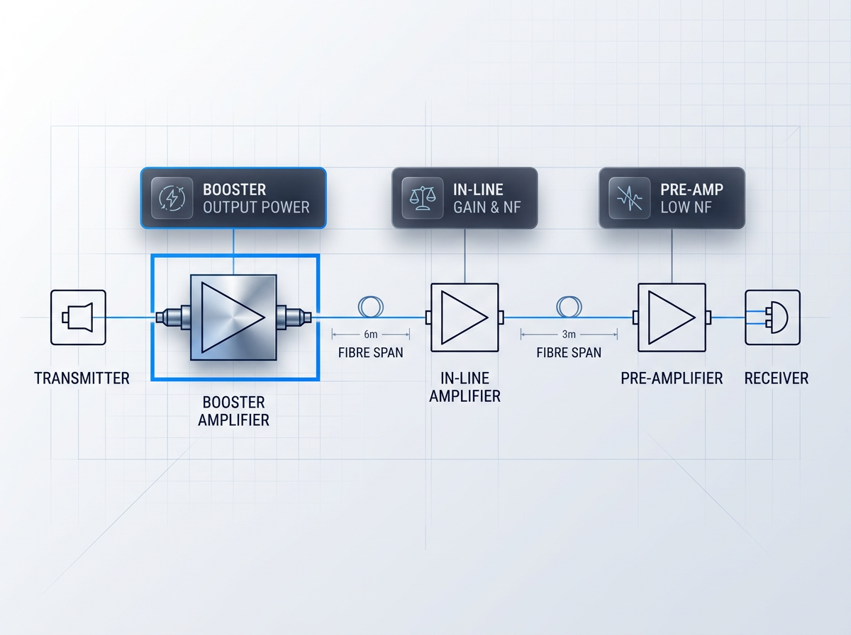
The booster optical amplifier sits immediately after the transmitter or multiplexer, before the first fibre span. Its position makes it the first amplification stage in the link — and that position defines its design priorities.
Saturated output power is the primary specification. The booster must launch the signal at the level the span demands; gain balance and noise figure are secondary considerations here.
Pre-amplifiers prioritise low noise figure for weak receiver-end signals; in-line amplifiers balance gain and noise. The booster trades that balance for maximum launch power, with gain flatness and thermal load as the consequent engineering constraints.
Power Determines Link Distance
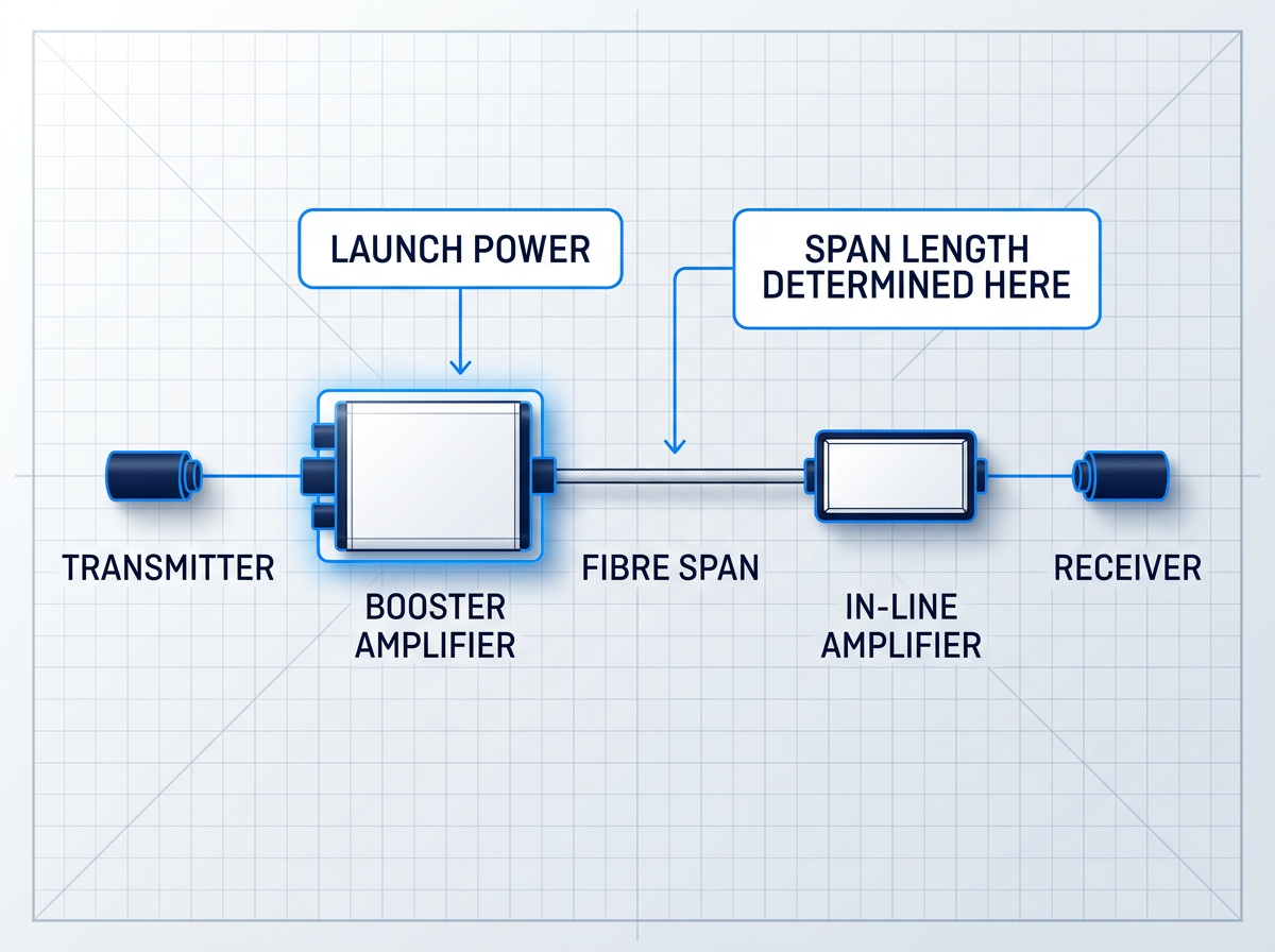
In the booster position, saturated output power is not one specification among many — it is the specification. The amplifier sits at the transmitter end, and what it launches into the span sets the ceiling on achievable link distance.
Higher launch power extends the span before the signal degrades to a level that demands re-amplification. Lower launch power compresses it. Every other parameter in the booster's design serves this primary axis. If the output power is insufficient, the link does not perform — regardless of what else the amplifier does well.
WSL Builds Where Others Stop
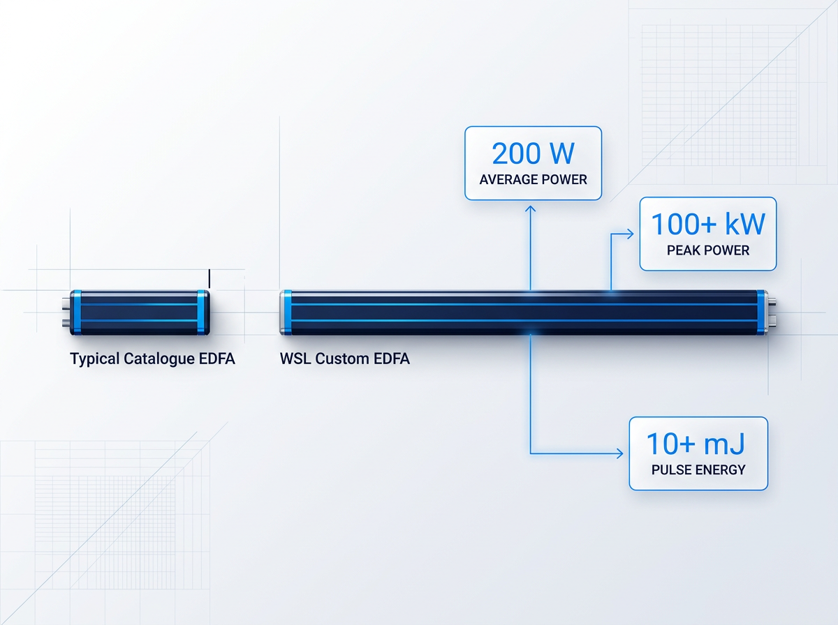
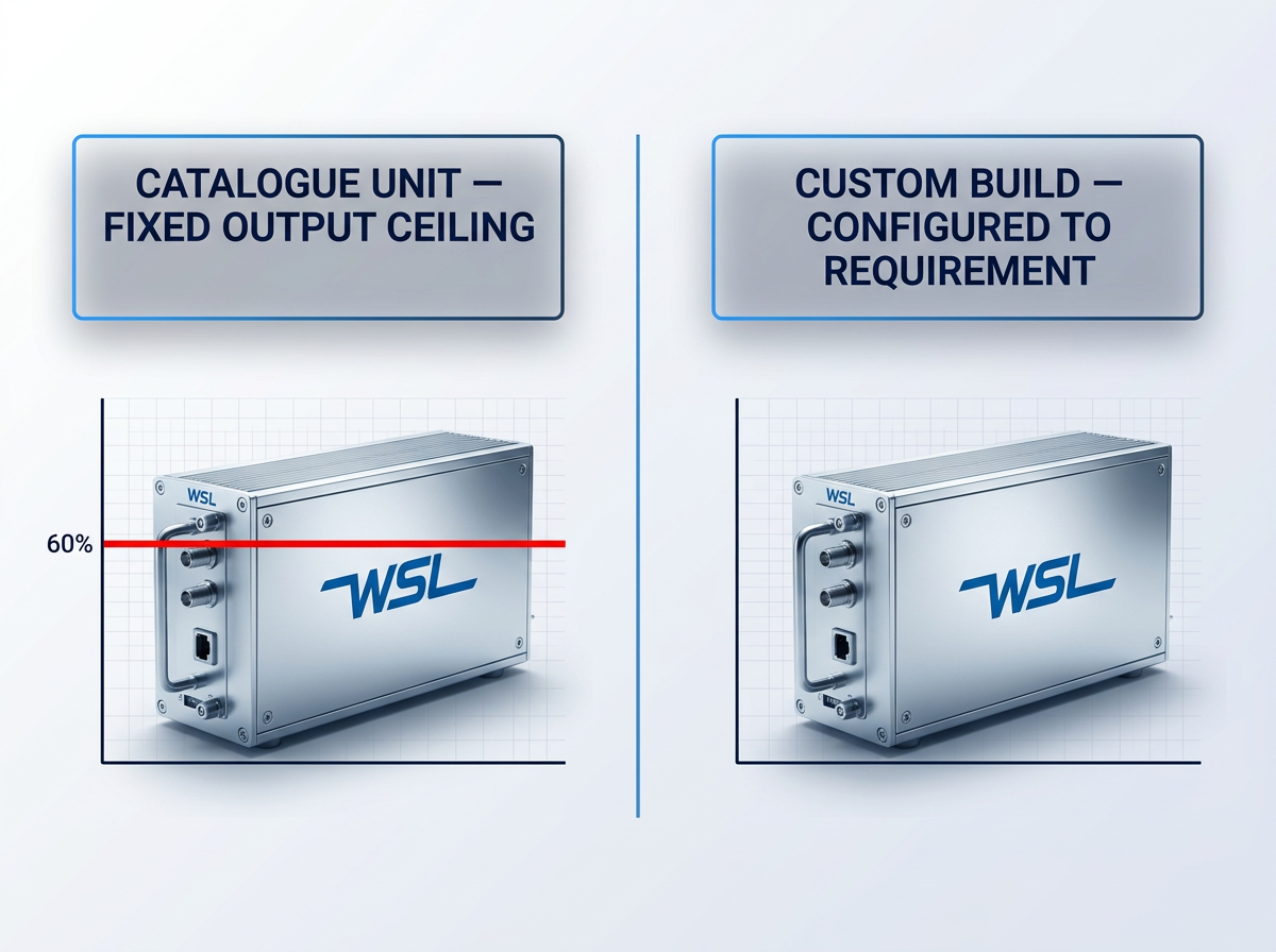
Most catalogue EDFAs deliver less than 50 W average power, and it is rare to see one above that level. WSL builds from low-power units through to 200 W or more average power — the highest average powers commercially available.
Output is tunable from 0 to 100% of rated power, so the amplifier adapts to the link budget rather than forcing the system design to work around a fixed output. Every unit is built to the client's actual power requirement, specified per project.
Peak Power Above 100 kW
Where the transmitter operates in a pulsed regime, average power is only part of the picture. The specifications that govern performance are pulse energy and peak power — and these demand a different class of amplifier design.
WSL builds pulsed booster EDFAs to pulse energies above 10 mJ and peak powers above 100 kW. For applications such as LiDAR, remote sensing, and short-pulse communications, these figures represent the threshold between an amplifier that is fit for the role and one that is not.
Fixed Builds Set a Hard Ceiling
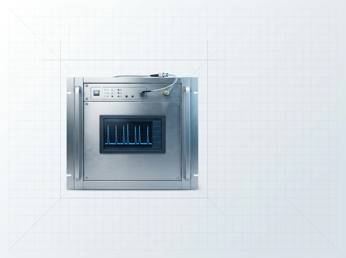
A fixed-catalogue EDFA sets its power ceiling at manufacture. When a booster application's requirement exceeds that ceiling, the system designer has no recourse — the application must be re-engineered around the amplifier's limit, not the other way around.
The custom-build model removes that constraint entirely. Each WSL unit is configured to the application's actual power requirement from the outset. There is no catalogue tier to fit within, no ceiling to engineer around. For demanding booster applications, this is not a preference — it is the rational engineering answer.
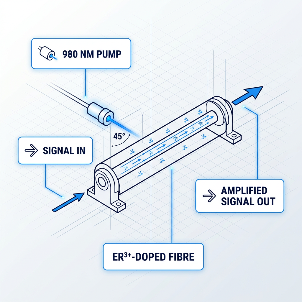
Erbium Fibre, Optical Amplification
Pump laser diodes at 980 nm excite erbium ions in the doped fibre to a higher energy state. When signal photons pass through, they trigger stimulated emission — producing an amplified copy of the signal at the same wavelength, phase, and direction.
The process is entirely all-optical: no O-E-O conversion, no electrical domain, no signal reconstruction. Signal integrity is preserved through the gain medium — a defining property of the EDFA platform that the custom EDFA is built on.
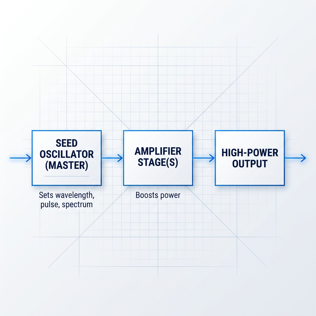
Seed, Amplify, Scale
The custom EDFA is built on a MOPA (master oscillator power amplifier) architecture. A low-power seed oscillator establishes the signal's properties — wavelength, spectral characteristics, pulse shape — with precision. Successive amplifier stages then boost that signal to the required output power.
The seed stage is where signal quality is set; the amplifier stages are where power is delivered. This staged separation is the architectural foundation of the custom EDFA's capability.
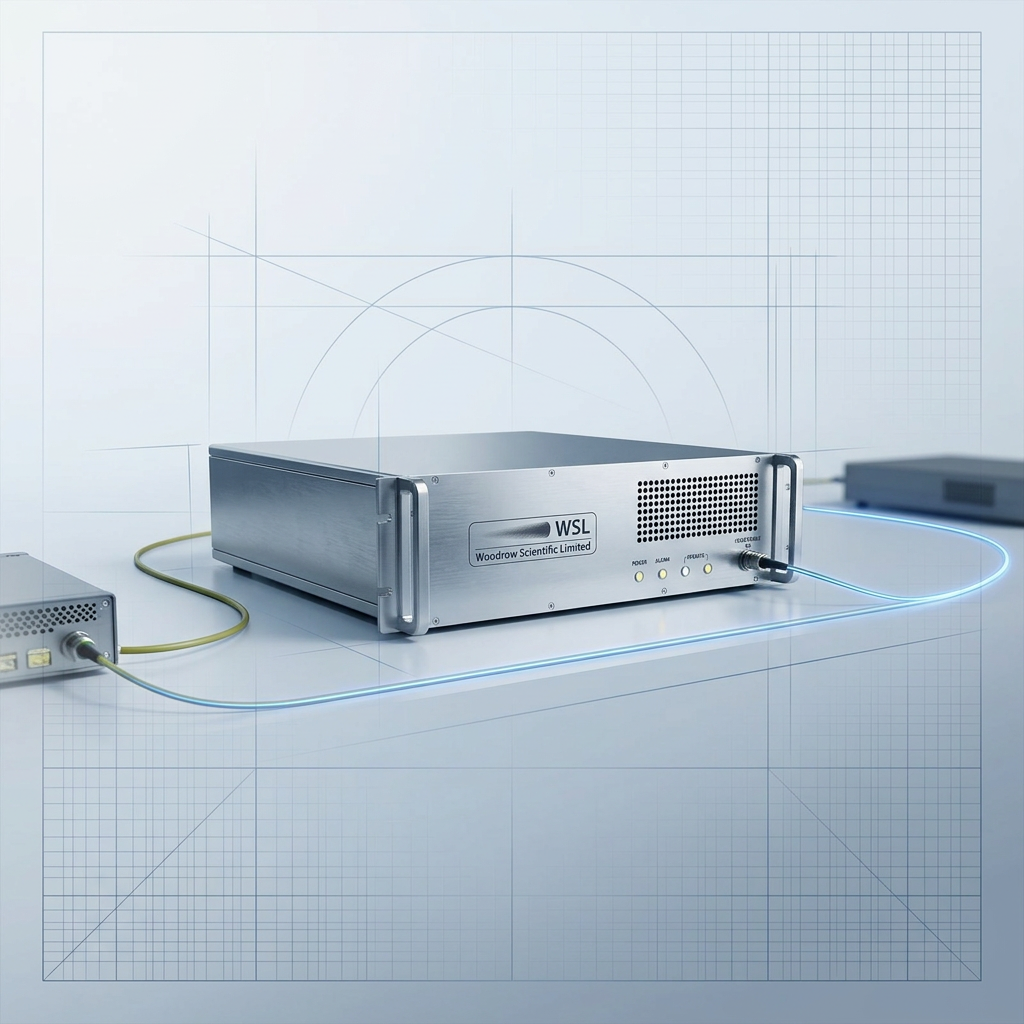
Built for the Booster Role
In the booster position, the amplifier must faithfully reproduce the transmitter's signal at the power level the link budget demands. MOPA's staged architecture is precisely suited to this: signal properties are fixed at the oscillator before amplification begins — wavelength, spectral purity, and pulse regime are not retrofitted at the output.
This is why the custom EDFA supports both CW and pulsed operation, and why output power is tunable from 0 to 100% of rated output — the architecture makes that flexibility inherent, not added on.
1530–1625 nm Erbium Gain Window
The natural amplification band of erbium-doped fibre spans 1530–1625 nm, covering the C-band (1530–1565 nm) and L-band (1565–1625 nm). This is the operating window of long-haul fibre communications — the region where silica fibre attenuation is lowest and erbium gain is available.
The custom EDFA operates across this full window: C-band, L-band, or dual C+L delivered from a single source through one cable.
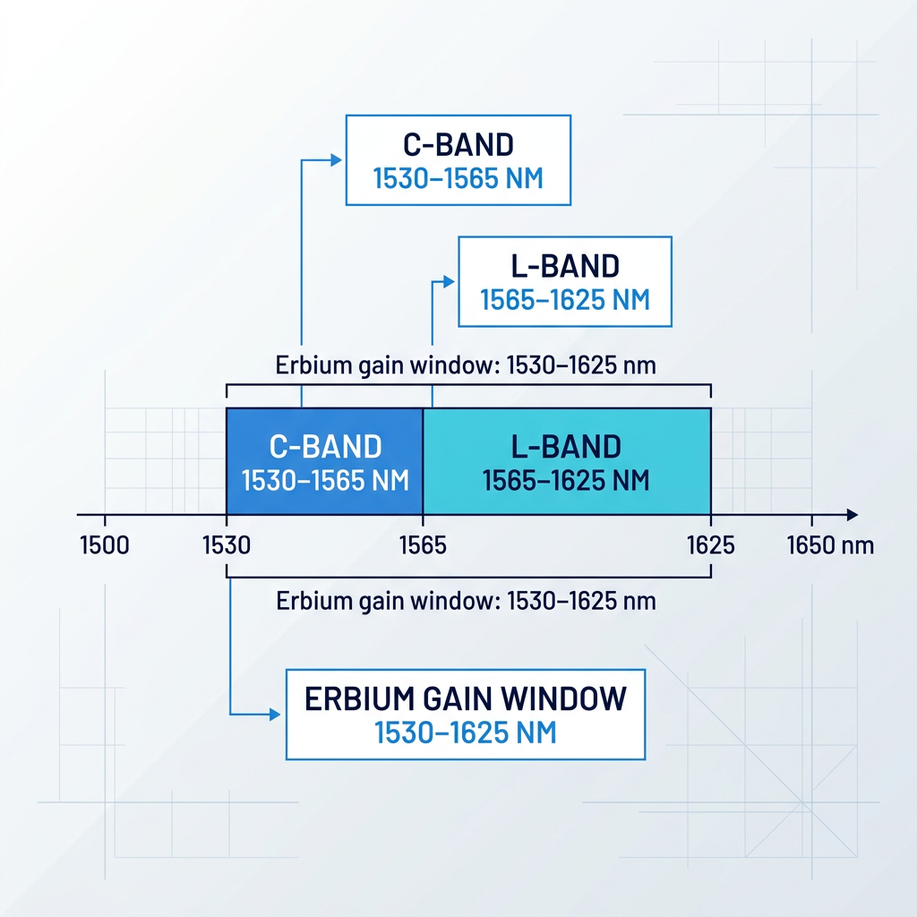
C-Band, L-Band, or Both
The operating band is specified per project: C-band (1530–1565 nm), L-band (1565–1625 nm), or dual C+L from a single unit through one cable.
Dual-band deployments that rely on separate amplifiers for each band introduce a second unit, a second cable, and a second integration problem. The custom EDFA eliminates that — both bands from one source, one connection, one engineering engagement.
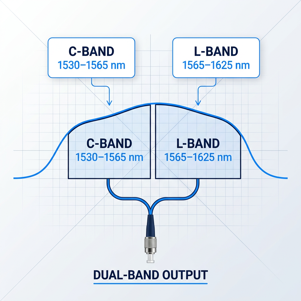
Specified to Your Link Budget
Output power is set per project to match what the link budget demands. There is no fixed catalogue tier to work around. Every unit is built to the client's requirement, with output controllable from 0 to 100% of rated power.
For pulsed booster applications, pulse energy above 10 mJ and peak power above 100 kW are achievable — specifications that go well beyond what fixed-catalogue builds address.
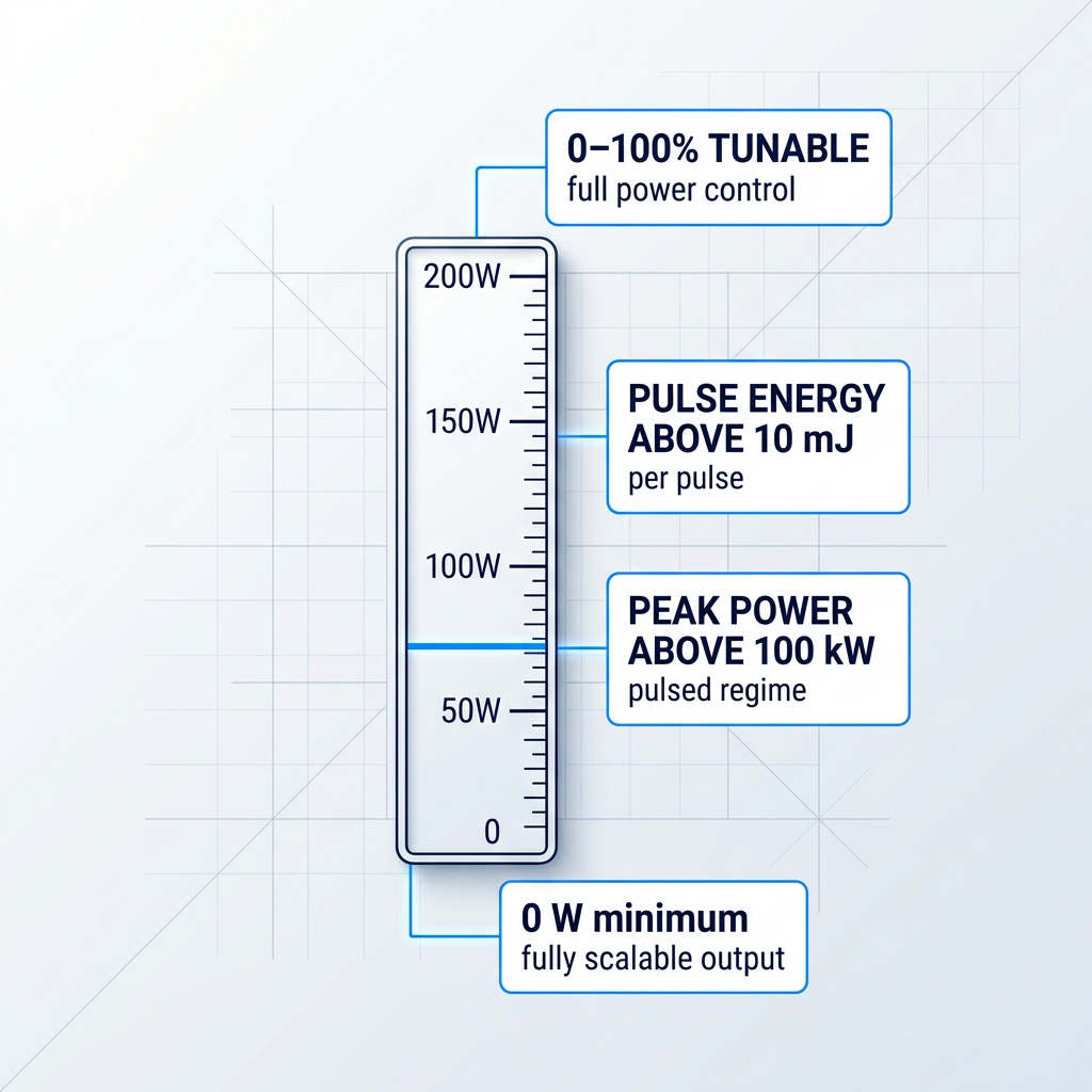
CW, Pulsed, or Custom
A CW communications link and a pulsed ranging or sensing system impose fundamentally different requirements on the booster amplifier. The pulse regime — CW, short-pulse (100–500 ns), or a custom format — is configured to match the transmitter.
The amplifier is built around the modulation format, not the other way around. This removes the compromise that arises when a fixed-regime amplifier is pressed into a mismatched application.

Integration-Ready, Air or Water
Air-cooled as standard — no chiller, no coolant loop, no ancillary infrastructure required. This simplifies transmitter-end integration considerably. For higher-output deployments, water cooling is available as a configured option.
Form factor and integration envelope are specified per project. The amplifier is built to fit the installation, whether that is a compact OEM enclosure or a specific rack geometry — not adapted from a generic chassis.
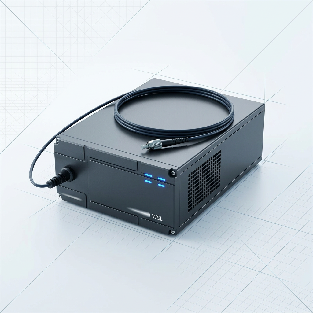
Control Built to Your Standards
Control firmware and communication standards are configured per project. At the transmitter end, the amplifier must speak the host system's control language — firmware that does not match the host's architecture creates integration friction that a custom build removes from the outset.
Delivery cable length and termination are also specified per project, resolving the final physical interface detail before the unit ships.
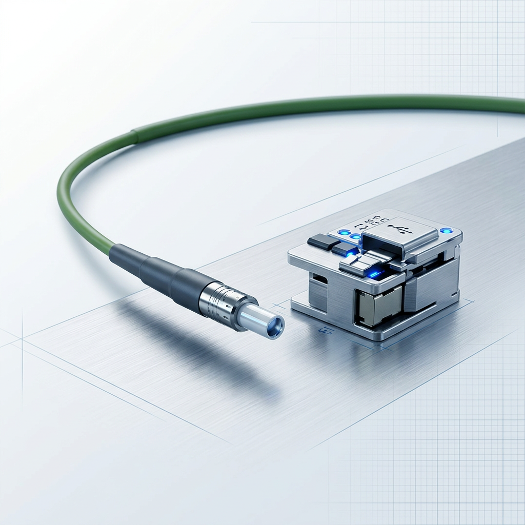
Heat Is a Primary Design Variable
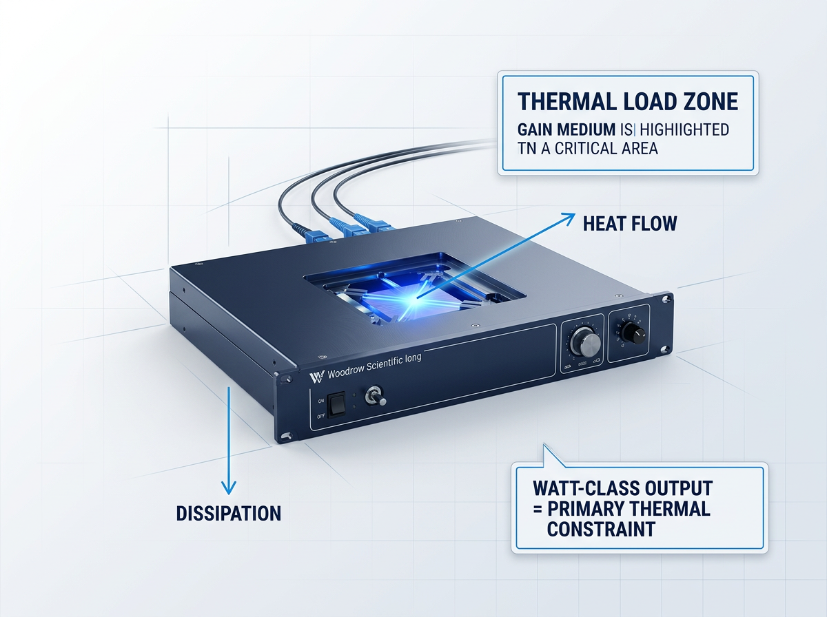
At watt-class output levels, a booster optical amplifier generates substantial heat as a direct consequence of its optical output. That thermal load is not a secondary consideration to be addressed once the optical design is otherwise settled.
It is a primary engineering constraint — one that shapes the amplifier's architecture and the integration plan at the transmitter end. Cooling architecture must be specified at the outset, not resolved during commissioning.
Standard Build, No Ancillary Infrastructure
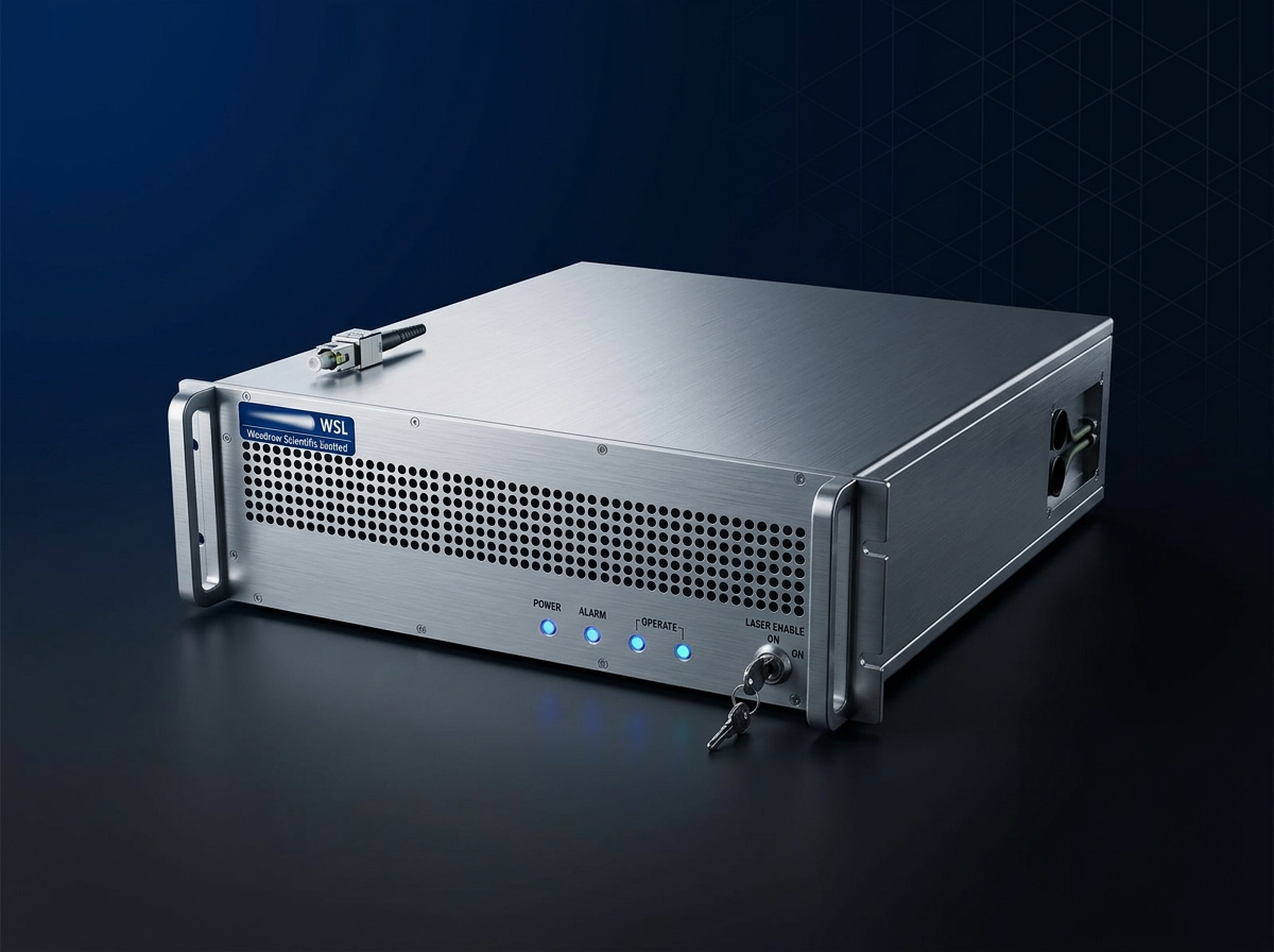
Air-cooled as standard — no chiller, no coolant loop, no fluid-handling requirements. This simplifies transmitter-end integration considerably: fewer subsystems to install, commission, and maintain.
For most booster deployments, air cooling is the right engineering answer. The standard build is self-contained and integration-ready, removing a category of ancillary infrastructure from the system design entirely.
Specified at Design Time, Not Retrofitted
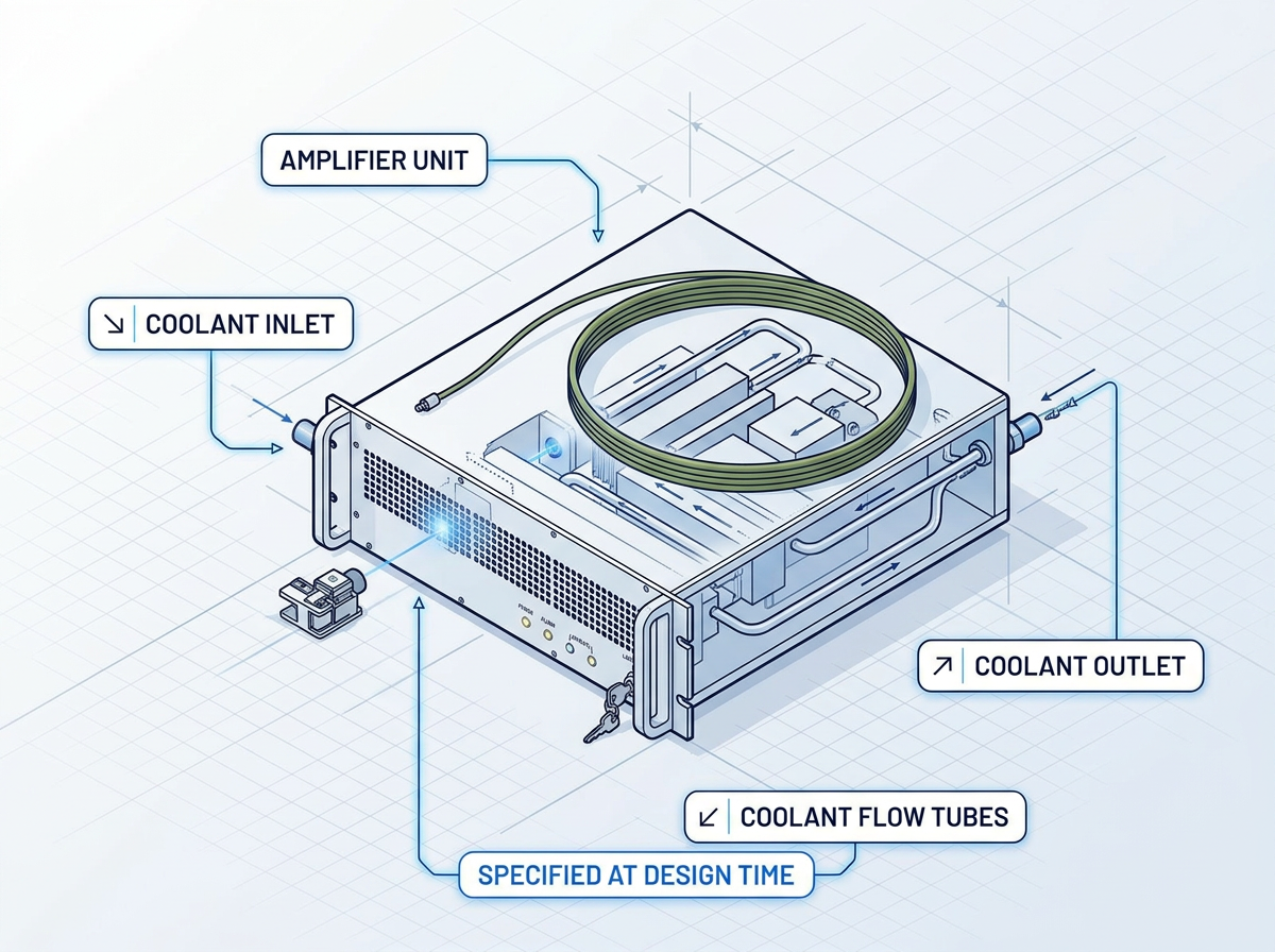
Where output power levels or environmental constraints make air cooling insufficient, water cooling is available as a configured option. For those deployments, it is the correct engineering answer — not an edge case.
The choice between air and water cooling belongs in the initial system specification. Retrofitting a cooling solution after integration is costly and often impractical. The platform is engineered to support either option from the start, covering the full range of booster output requirements.
Gain Flatness and Noise Figure at the Booster Stage
At the transmitter end, gain flatness is the primary spectral priority. Noise figure matters for the OSNR budget but is weighted differently here than in a pre-amplifier role.
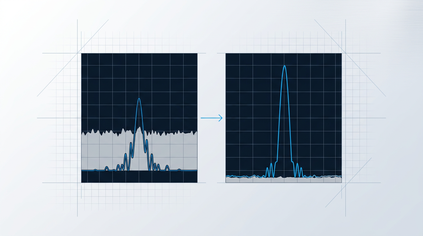
Noise Figure: Real but Not the Primary Constraint
High input power at the booster stage suppresses ASE naturally. NF still contributes to link OSNR, but is not the dominant spectral design constraint here.
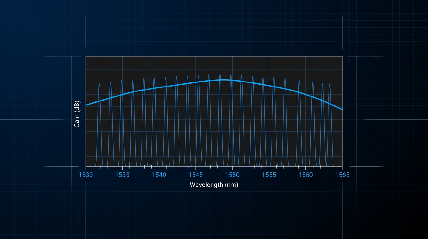
Gain Flatness: The Priority for WDM Booster Design
Erbium gain is not spectrally flat. Per-channel gain errors at the booster stage accumulate through every downstream amplifier, compressing OSNR margin across the channel plan.
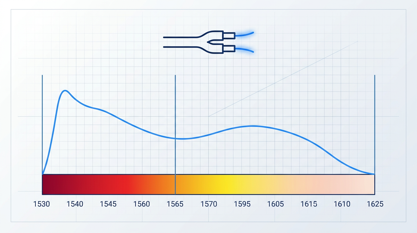
1530–1625 nm: C-Band and L-Band from One Source
The 1530–1625 nm window covers both C-band and L-band. A single cable delivers both, removing the need for a second amplifier at the transmitter end.
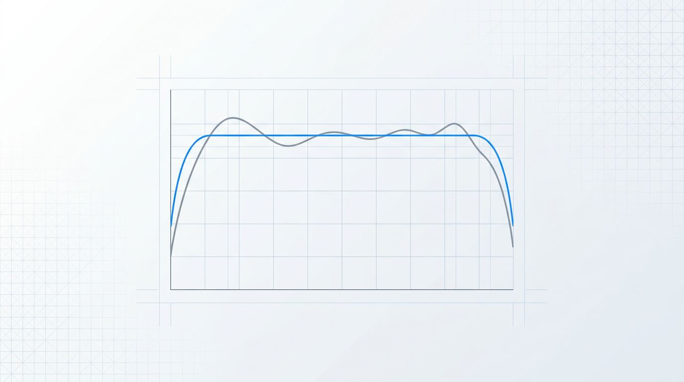
Gain-Flattening Filters Address Residual Spectral Tilt
Residual gain tilt is addressed through gain-flattening filters and deliberate gain profile design, matched to the flatness requirements of each booster application.
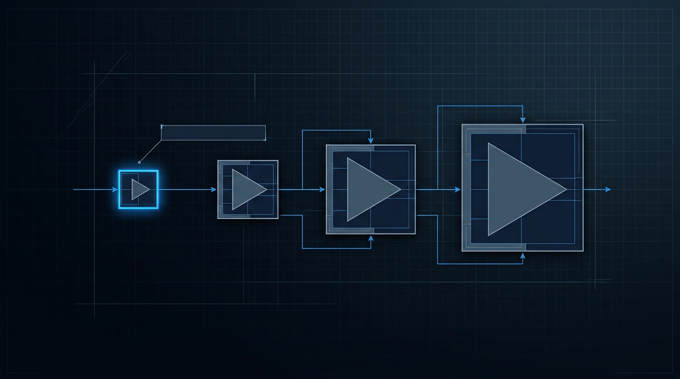
MOPA Architecture: Gain Profile Designed for the Application
WSL's MOPA architecture sets the gain profile at the seed stage — spectral characteristics designed around the booster application, not fixed by a catalogue unit.
Designed, Built, and Supported In-House by WSL
WSL designs, builds, qualifies, and supports its EDFAs entirely in-house. For a system-critical role like the booster position, that is the difference between a supplier who can solve your integration problem and one who cannot.
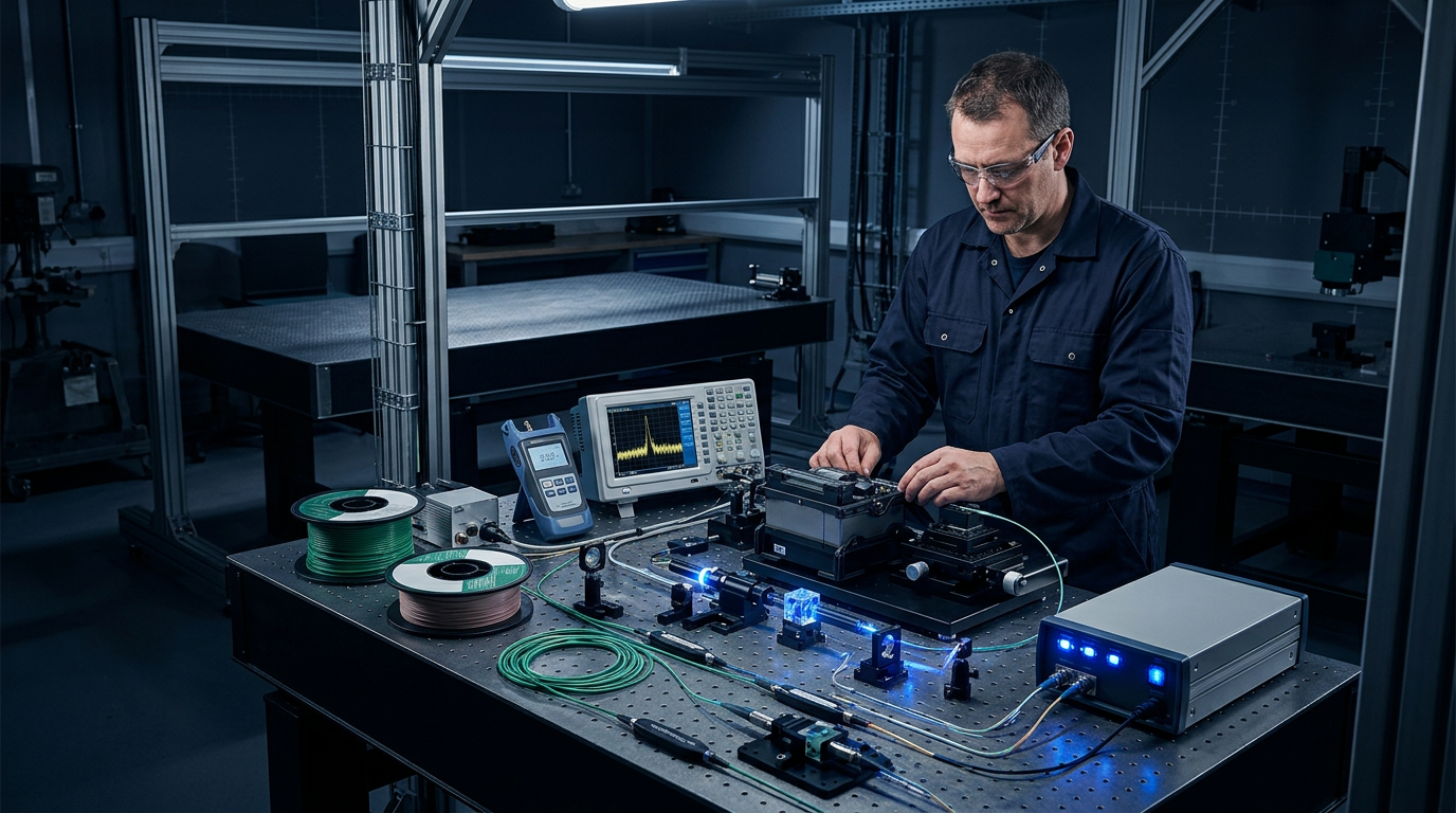
In-House Design, Build, Qualification, and Support
WSL is a manufacturer, not a reseller — every amplifier designed, built, and qualified in-house.
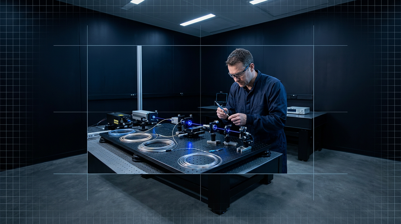
Rooted in Southampton's ORC, Birthplace of the EDFA
WSL's fibre-amplifier expertise traces directly to the ORC team that invented the technology.
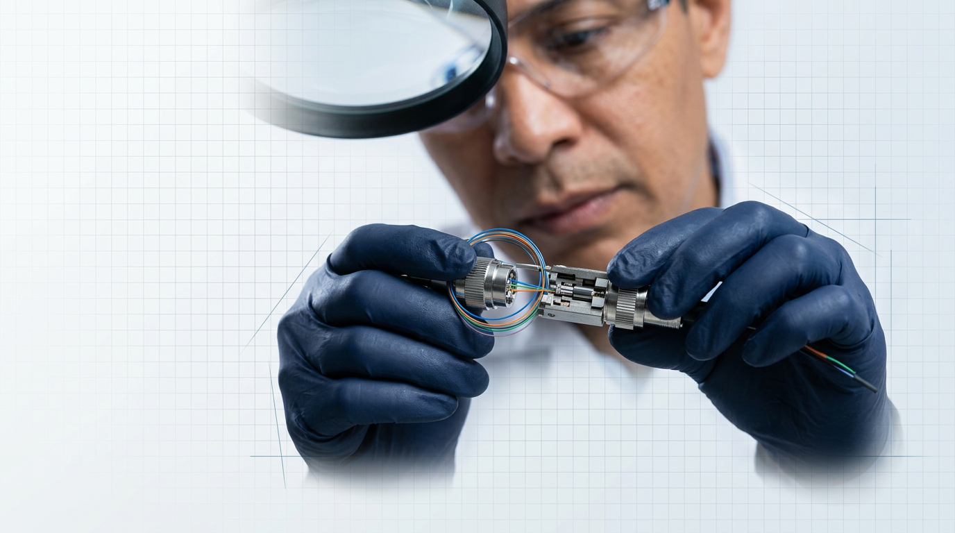
200+ Years of Combined Engineering Experience
Over 200 years of combined engineering experience, built on patented in-house technology.

Many EDFA Suppliers Are Resellers, Not Manufacturers
Resellers carry no in-house engineering — slower support, no ability to modify the product.

Direct Access to the Engineers Who Built Your Amplifier
Faster integration support and faster resolution — direct from the original developers.
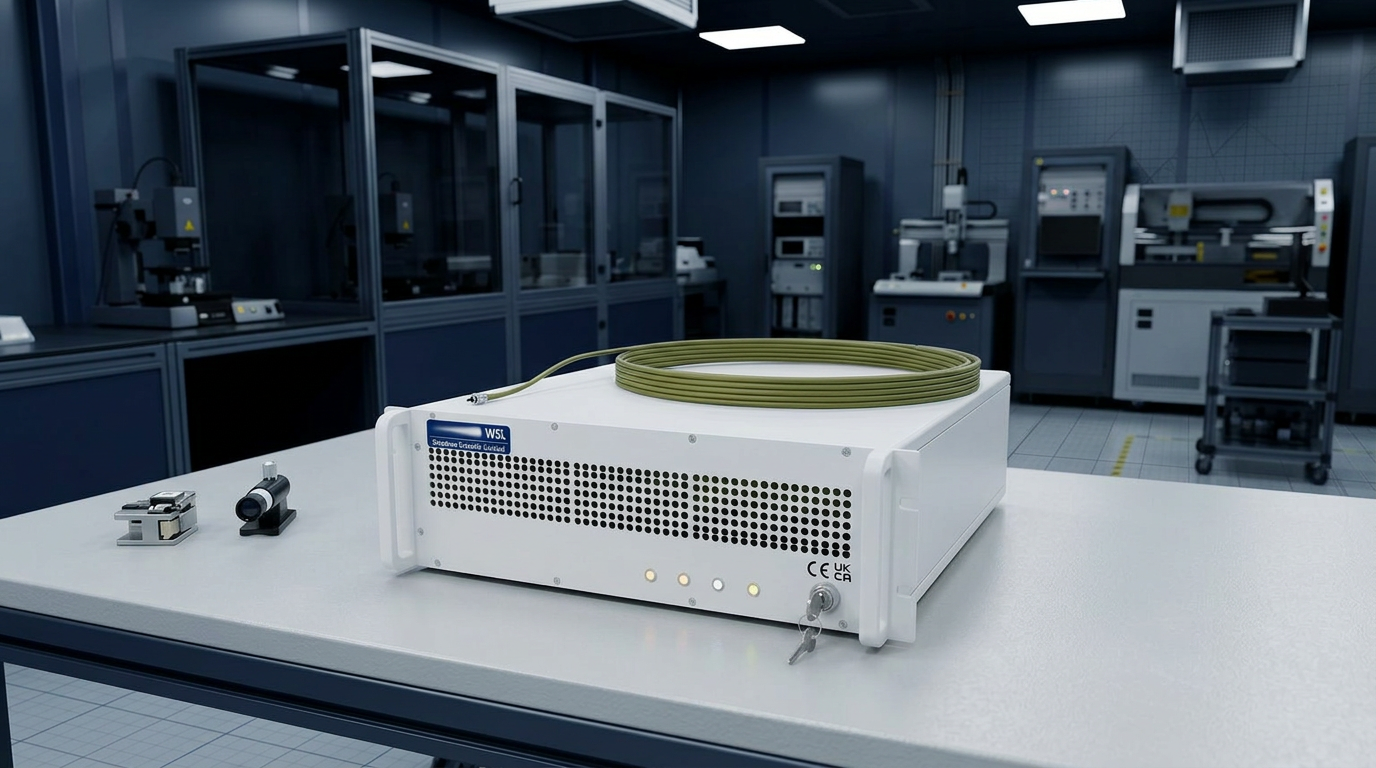
CE and UKCA Certified, Built in Southampton, UK
CE and UKCA certified. Designed and built in Southampton, UK. Supplied worldwide.
EDFA Built for Free-Space Optical Communications
The EDF-UL-10 is WSL's application-specific build for the FSOC uplink role. Explore the full FSOC product page or download the datasheet to review the specifications.

Why Demanding Booster Applications Require a Custom EDFA
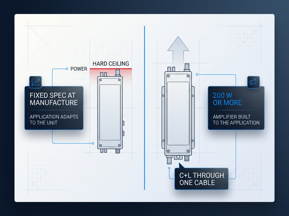
A fixed-catalogue EDFA sets its output power, band, and form factor at manufacture. In a demanding booster application, the system must adapt to the amplifier — not the other way around. For requirements that push against those fixed limits, this is a structural compromise.
Most catalogue EDFAs deliver less than 50 W average power. WSL's custom platform scales to 200 W or more, built to the client's requirement with output tunable from 0 to 100% of rated power.
For dual-band deployments, WSL delivers C-band and L-band through one cable — no second amplifier required.
Starting Your Custom Booster EDFA Specification
Every unit is configured per project. Before or during the initial conversation, you will need to define your output power (average, peak, and pulse energy if pulsed), operating band (C, L, or C+L), pulse regime, cooling preference, form factor, and control firmware requirements.
The published specifications are what WSL has built so far, not a ceiling. Requirements beyond them are assessed directly with the engineers who designed the amplifier — nothing is ruled out in advance.
Frequently Asked Questions: Booster Optical Amplifiers
Technical questions about the booster amplifier role, custom EDFA specifications, and how to engage with WSL's engineering team — answered directly.
A booster optical amplifier sits directly after the transmitter or multiplexer, at the launch point of the fibre span. Its defining requirement is saturated output power — it must put the signal into the fibre at the level the link budget demands. Noise figure is a secondary concern here because the input signal is strong, which naturally suppresses ASE. An in-line amplifier sits mid-span to compensate for accumulated fibre loss; it requires a balanced design where both gain and noise figure matter. A pre-amplifier sits at the receiver end, ahead of the detector. There, the signal has traversed the full link and is weak — ASE competes directly with it, so noise figure is the primary design parameter. The three roles are optimised for power, balance, and sensitivity respectively. Choosing the wrong amplifier type for a given position degrades system performance at the architectural level.
WSL builds custom booster EDFAs from low-power units (e.g. 5 W) through to 200 W or more average power — the highest average powers commercially available. Output is fully tunable from 0 to 100% of rated power, so the amplifier adapts precisely to your link budget rather than forcing the system to work around a fixed catalogue level. For pulsed applications, pulse energies above 10 mJ and peak powers above 100 kW are achievable, configured per project. Most catalogue EDFAs deliver less than 50 W average power, and it is rare to see one above that ceiling. WSL's custom platform removes it entirely — every unit is built to the client's requirement.
The physics is straightforward: amplified spontaneous emission (ASE) is the dominant noise mechanism in an EDFA, and ASE is strongly suppressed when the input signal power is high. At the transmitter end, the booster sees a strong input signal — so ASE is held down naturally, and the noise figure measured at that operating point carries little practical weight. At the receiver end, the pre-amplifier sees a signal that has traversed the full link and suffered fibre attenuation. The input power is low, ASE grows rapidly relative to the signal, and noise figure becomes the critical design axis for preserving OSNR. This does not mean noise figure is irrelevant for a booster — it still contributes to the system OSNR budget across the full link. But it is not the primary design constraint. Saturated output power is, which is why booster EDFAs are optimised around it.
WSL's custom EDFA operates across the full erbium gain window: 1530–1625 nm, covering the C-band (1530–1565 nm) and L-band (1565–1625 nm). The operating band is specified per project — C-band only, L-band only, or dual C+L from a single unit through one cable. For dual-band booster deployments, that single-source delivery eliminates the need for a second amplifier at the transmitter end. One source, one cable, both bands — which simplifies integration and reduces the component count at the transmitter stage.
WSL's custom booster EDFA is air-cooled as standard — no chiller, no coolant loop, no ancillary fluid-handling infrastructure required. For most booster deployments, this is the correct engineering answer: it simplifies transmitter-end integration considerably. Where output power levels or installation environment make air cooling insufficient, water cooling is available as a configured option. The cooling architecture is a system-level decision made at design time. Retrofitting a different cooling approach after the unit is built is costly and often impractical, so the choice should be locked in when the output power and environmental constraints are defined. The flexible model — air as standard, water when needed — means the platform is suited to the full range of booster output requirements without forcing a one-size approach.
Only the erbium physics and the platform are fixed. Everything else is configured per project: operating band (C-band, L-band, or dual C+L); output power (average, peak, and pulse energy, specified to the application); pulse regime (CW, short-pulse such as 100–500 ns, or a custom format); cooling (air or water); delivery cable length and termination; form factor and integration envelope; and control firmware and communication standards. The published specifications represent what WSL has built to date, not the limit of what it builds. Requirements that go beyond them — a different power level, form factor, or environment — are assessed directly with WSL's engineers. Nothing is ruled out in advance. This depth of per-project tailoring is what distinguishes a custom-built EDFA from a catalogue unit selected from a fixed range.
An EDFA amplifies light by passing the signal through an erbium-doped fibre that has been excited by a pump laser, typically at 980 nm. The pump raises erbium ions to a higher energy state. When signal photons in the 1530–1625 nm window travel through the fibre, they trigger stimulated emission — the excited ions release energy as additional photons at the same wavelength, phase, and direction as the signal. The result is all-optical amplification with no optical-to-electrical-to-optical (O-E-O) conversion. In a MOPA (master oscillator power amplifier) architecture — the architecture used in WSL's custom EDFA — a low-power seed oscillator establishes the signal's properties with precision, and successive amplifier stages boost it to the required output level. This staged approach preserves spectral and temporal fidelity while scaling power to the levels a booster application demands.
The 1530–1625 nm operating window is eye-safer than legacy 1064 nm sources, but not unconditionally safe at all power levels. The mechanism is water absorption: the cornea and lens absorb radiation above approximately 1400 nm before it reaches the retina, which is the structure most sensitive to laser damage. This gives the 15xx nm band a significantly higher eye-damage threshold than 1064 nm, where light transmits through to the retina. As rp-photonics.com notes, erbium fibre systems at 1.5 µm are far less dangerous than 1 µm lasers at similar output powers — though at sufficiently high power, corneal damage remains possible. WSL's custom EDFA operates in this eye-safer wavelength range, and reduced-hazard-zone builds are available for applications where a smaller safety perimeter is a system requirement.
WSL's custom EDFA is CE certified and UKCA certified. CE marking confirms that the product meets the safety, health, and environmental protection requirements of the European Economic Area — allowing it to be placed on the EEA market without restriction. UKCA (UK Conformity Assessed) marking is the equivalent conformity mark for the Great Britain market. Holding both certifications means the amplifier is market-ready for deployment across the UK and Europe without additional conformity steps for the buyer.
The starting point is submitting your requirements for a specialist evaluation — not selecting from a catalogue. WSL's engineers assess each requirement directly with the client. To make that first conversation productive, bring the parameters that define your application: required output power (average, and peak power or pulse energy if pulsed); operating band (C-band, L-band, or dual C+L); pulse regime (CW, pulsed, or custom); cooling preference and installation environment; form factor and integration envelope; and control interface and firmware requirements. Requirements that go beyond the published specification are assessed directly — nothing is ruled out before that conversation. Submit your requirements for a specialist evaluation to begin.