

When a Catalogue Module Is a Compromise
Most EDFA modules are catalogue items: fixed gain, fixed output power, standard C-band, set form factor. For standard telecom deployments, that model works well.
For demanding applications, it does not. Requirements for higher output power, short-pulse rather than CW operation, dual-band coverage, or custom control firmware fall outside catalogue ceilings — forcing system designers to compromise around the module rather than the other way around.
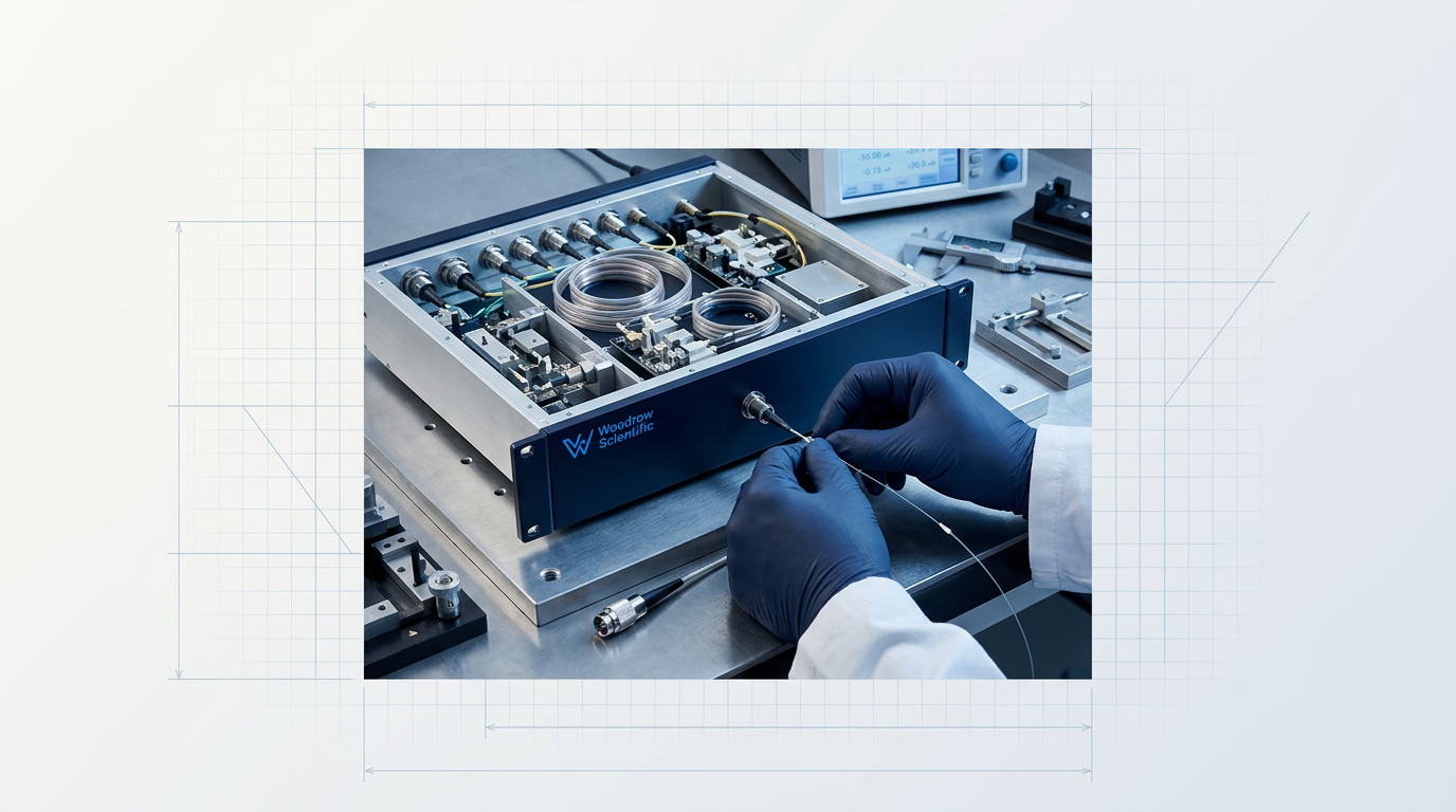
A custom-engineered EDFA module inverts this: only the erbium physics and platform are fixed; band, power, pulse regime, cooling, form factor and firmware are configured per project. The sections below cover what can be specified.
C-band, L-band, or Both
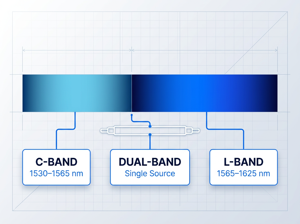
The module operates across the full 1530–1625 nm window: C-band (1530–1565 nm), L-band (1565–1625 nm), or dual C+L configured per project.
Dual C+L delivers both bands from a single source through one cable, removing the need for a second amplifier in your system. The operating band is set at the project stage — only the erbium physics and the platform are fixed; everything else is configured to your requirement.
From 5 W to 200 W+
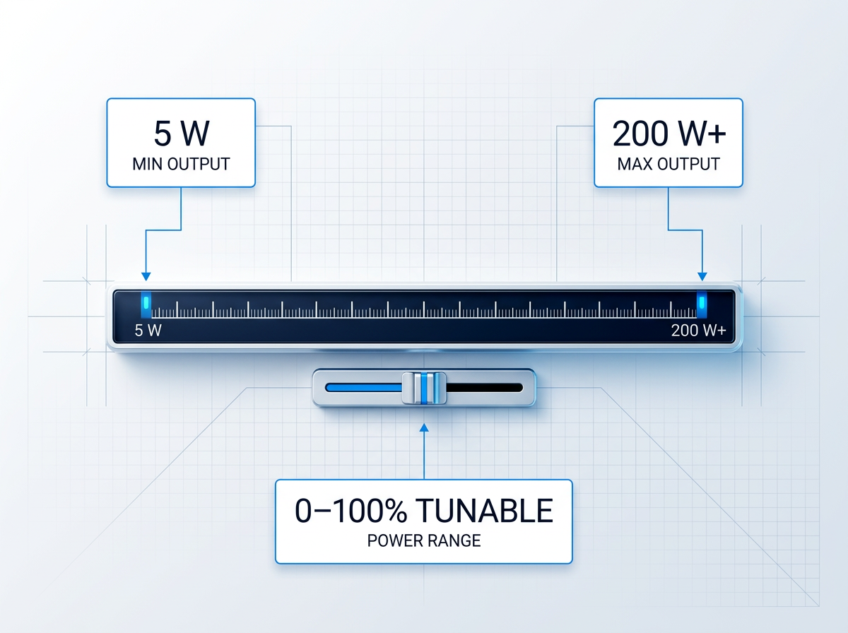
Average output power is specified per project, from low-power builds (e.g. 5 W) up to 200 W or more. Most EDFAs on the market offer less than 50 W; builds above that are uncommon.
Output is fully tunable from 0 to 100% of rated power, so you can operate at any point within the rated envelope without needing a separate attenuator or control stage.
CW, Pulsed, or Custom
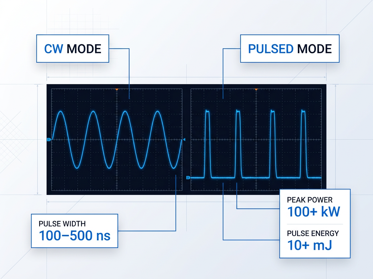
Pulse regime is configurable: CW, short-pulse (e.g. 100–500 ns), or a custom regime specified per project. The MOPA (master oscillator power amplifier) architecture underpins both modes, enabling power scaling without degrading beam quality.
For pulsed applications, pulse energy above 10 mJ and peak power above 100 kW are achievable — both configurable to your requirement. These three parameters are closely coupled and are specified together at the project stage.
Built Around Your System
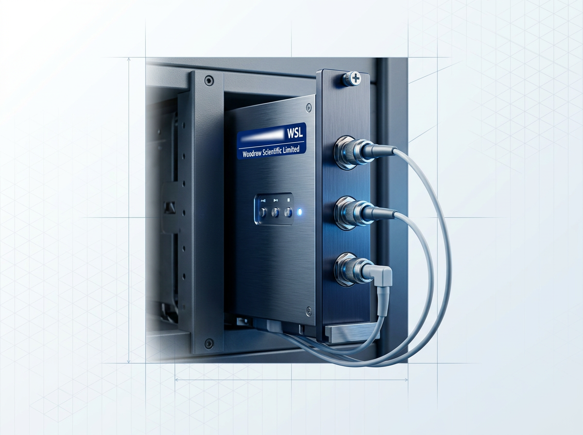
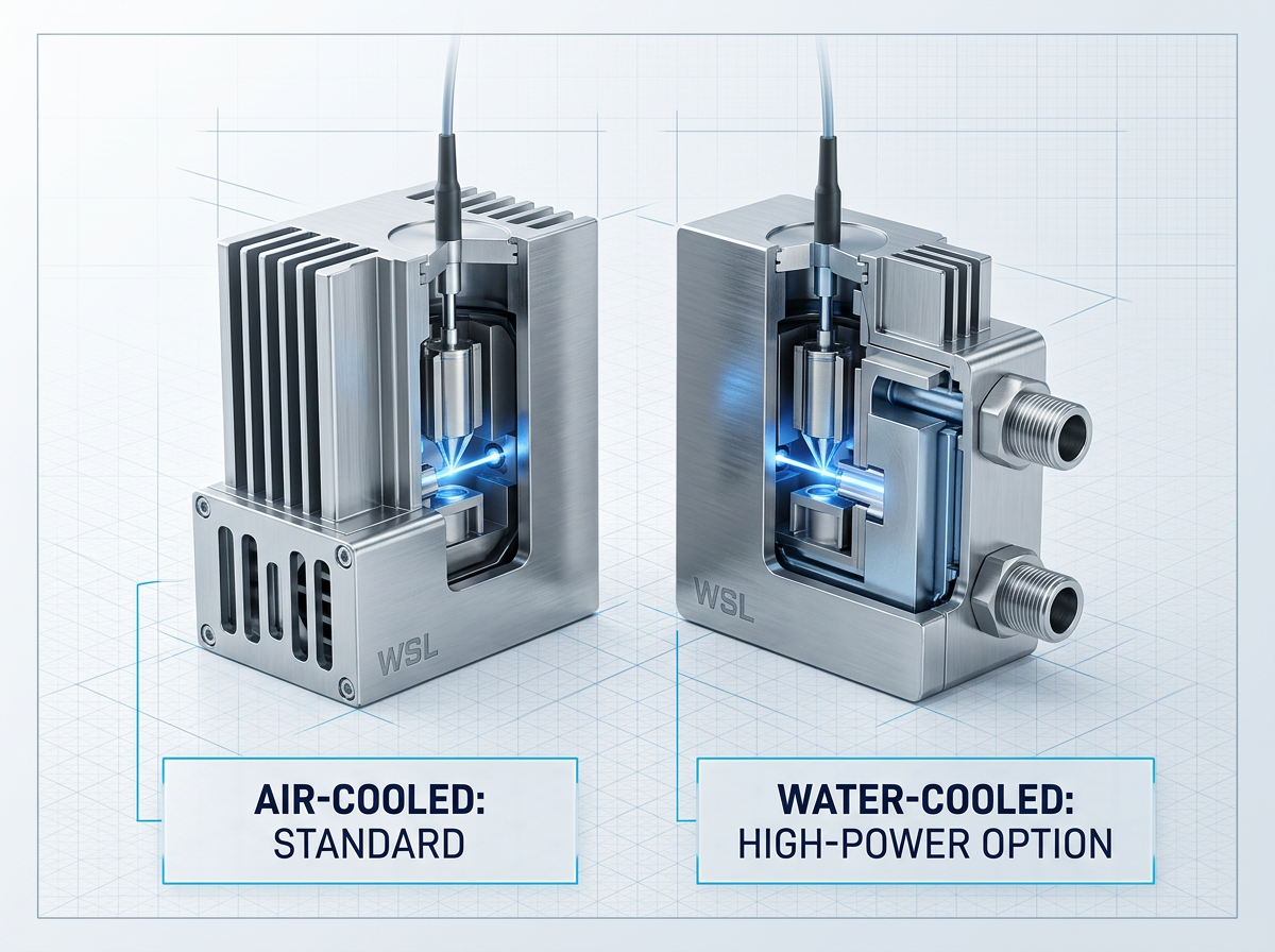
The module is air-cooled as standard — no chiller or coolant loop required, which simplifies integration directly. Water cooling is available as an option for high-power builds.
Delivery cable length and termination are specified per project. The form factor and integration envelope are custom: the module is designed to fit your system, not the other way around.
Custom Firmware and Protocols
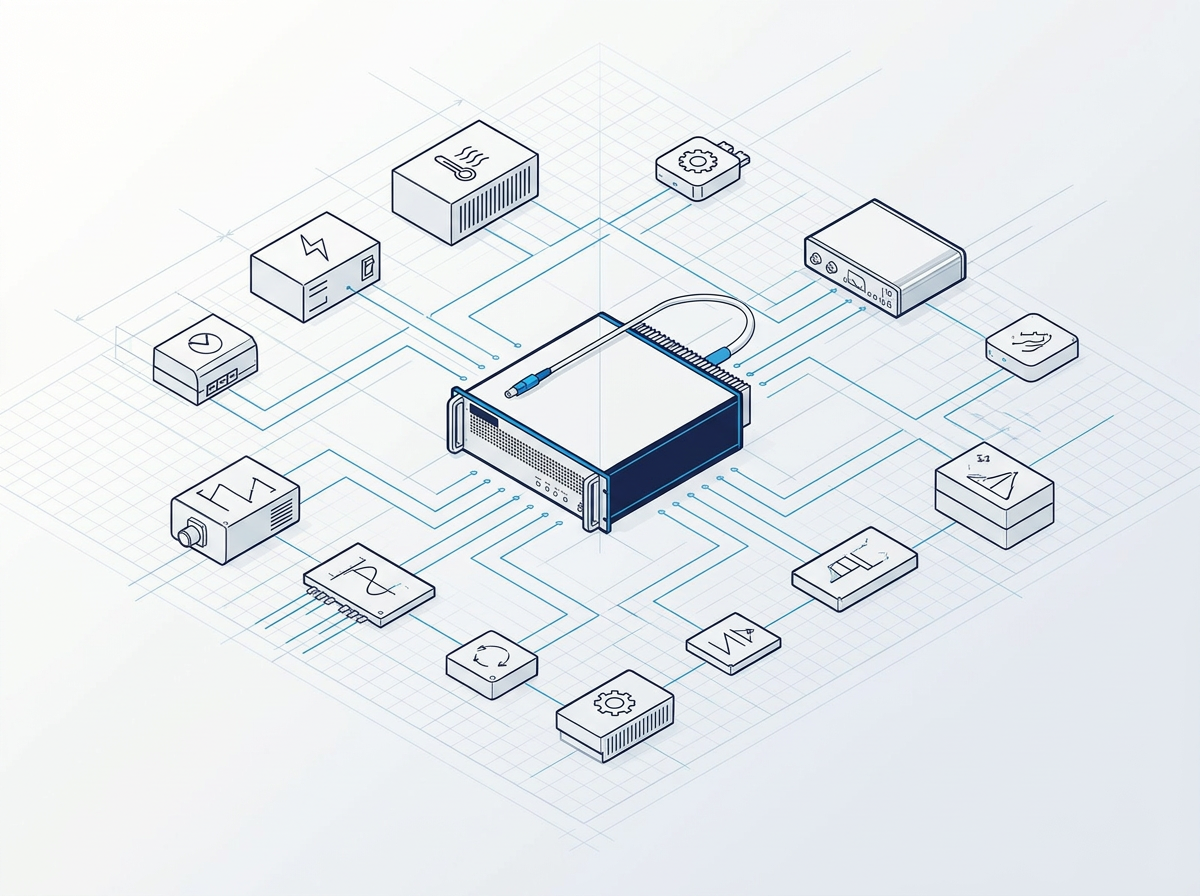
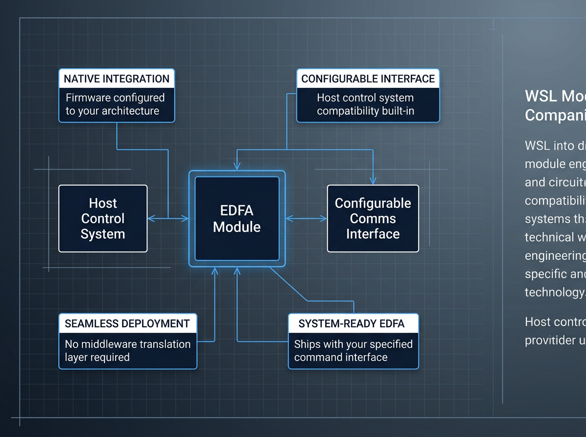
Control firmware and communication standards are configurable per project. For OEM and system-level integrators, this means the module can be built to your host control architecture's interface requirements rather than forcing an adapter layer.
A module that speaks your protocol behaves as a native component of your system from day one — a genuine engineering consideration, not a checkbox.
Power Output: From Low-Power Builds to 200 W and Beyond
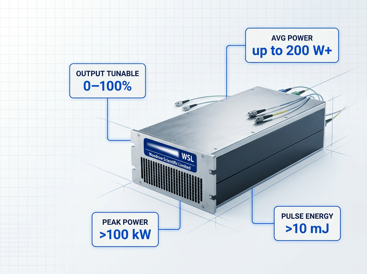
Most commercial EDFA modules offer less than 50 W average output power, and builds above that are uncommon. WSL covers the full range — from low-power units to 200 W or more, the highest average power commercially available — with pulse energies configurable to above 10 mJ and peak powers above 100 kW, each specified per project.
Every build is fully tunable from 0 to 100% of rated output. The MOPA architecture maintains beam quality as power scales. Air cooling is standard; water cooling is available for high-power builds.
1550 nm: Eye-Safer Wavelength for Demanding Deployments
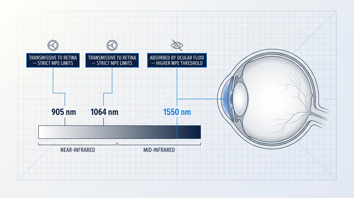
Wavelengths above approximately 1400 nm are absorbed by the aqueous and vitreous humour before reaching the retina. At 1550 nm, the maximum permissible exposure is significantly higher than at 1064 nm, where Nd:YAG sources are transmissive to the retina and subject to the same strict limits as visible wavelengths.
That higher threshold determines how much power is deployable in open-air and manned environments without triggering the constraints that limit 905 nm and 1064 nm systems. WSL builds across the full 1530–1625 nm window, with reduced-hazard-zone builds available where minimising the laser hazard zone is a design requirement.
Applications This EDFA Module Platform Is Built For
From sensing and communications to defence and industrial processing, each application domain has its own parameter requirements. Find yours below.

LiDAR: Automotive, Atmospheric and Airborne
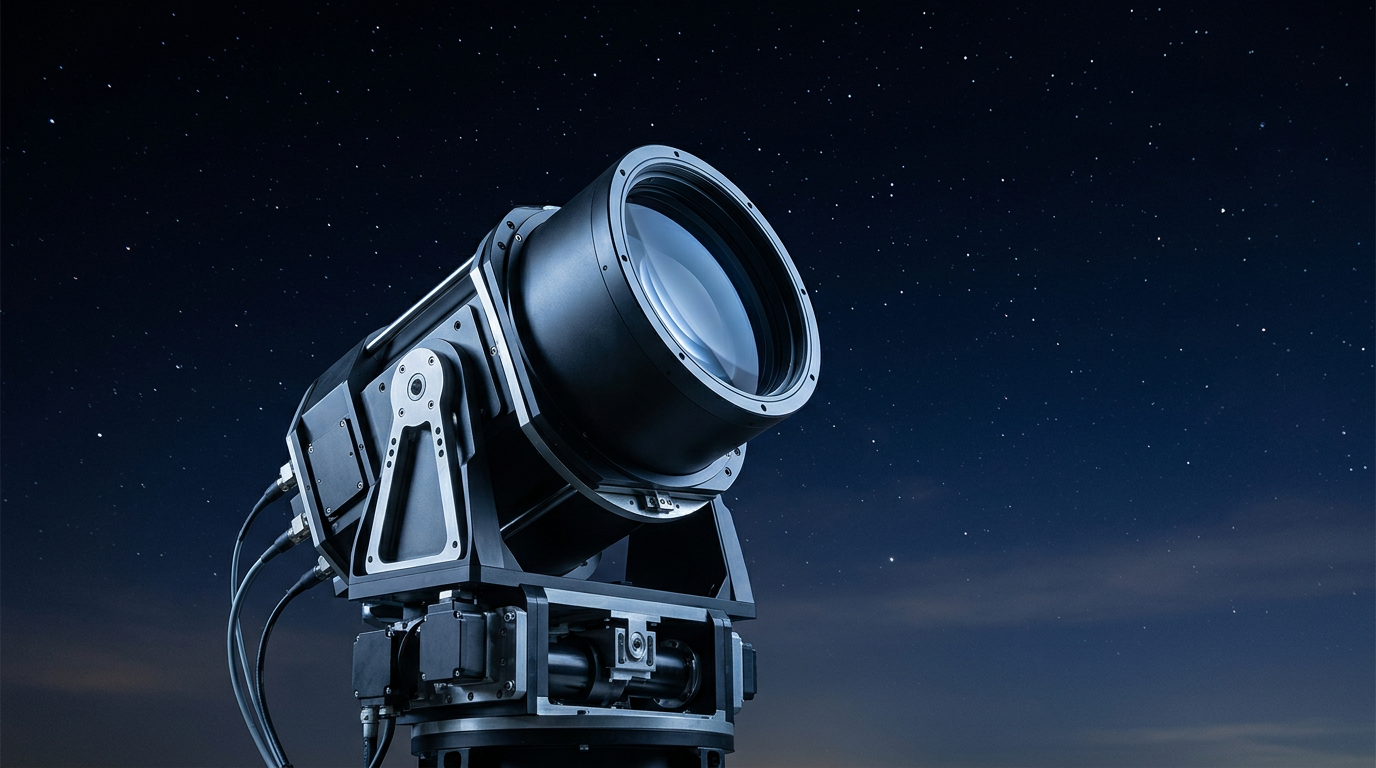
Higher permitted pulse power at 1550 nm enables longer-range detection. Short-pulse regime (100–500 ns) and high peak power are the decisive parameters.
Free-Space Optical Communications (FSOC)
Ground-station uplink and beacon amplification demand high average power in C-band or L-band. The EDF-UL-10 is an example configured build for this application.

Quantum Sensing and Communications
1550 nm is the standard wavelength for quantum key distribution and quantum sensing. Low-noise C-band or L-band amplification is the critical parameter at specification stage.

Distributed Acoustic and Structural Sensing
DAS and structural sensing systems require stable, high-power CW amplification at 1550 nm. Power stability and CW operation are the parameters that determine system performance.

Defence and Directed-Energy Research
Power ceiling is the deciding parameter. Builds reach 200 W or more average power, above 10 mJ pulse energy, and above 100 kW peak power.

Industrial Processing and OEM Gain Block
Marking, cleaning, paint removal and texturing at 1550 nm. OEM buyers can integrate the module as the gain engine, with custom firmware and comms.

Scientific and Research Instrumentation
Research programmes with non-standard requirements need an amplifier engineered to match. Band, power, and pulse regime are all configurable to the experimental specification.
Cooling Configuration Specified at Project Stage
Air-cooled as standard: no chiller or coolant loop is required, which keeps integration straightforward for most host systems. For high-power builds where thermal load demands more effective heat removal, water cooling is available — though it requires a coolant interface in the host system, a design consideration best resolved before integration begins.
Cooling configuration is specified at project stage alongside every other parameter. State your integration constraints upfront and the module is built to match them.
Firmware and Communications Built to Your Architecture
A catalogue EDFA module ships with a fixed command interface. If that interface doesn't map onto your host control architecture, you're left adapting your system to the module, building a middleware translation layer, or accepting a degraded integration — none of which belongs at the system design stage.
WSL's control firmware and communication standards are configurable per project. The module is specified to your interface requirements from the outset. For OEM integrators and system builders — including remote or unattended deployments where the management interface must be right by design — this is what native integration looks like.
Built by the Engineers Who Designed It
Many EDFA module suppliers are resellers rather than manufacturers. Without in-house engineering, post-supply support is slower, deep customisation is not possible, and the product cannot be improved over time. For a demanding or long-lifecycle application, that distinction is felt after delivery.
WSL designs, builds, qualifies, and supports its own amplifiers in-house, on patented technology, backed by 200+ years of combined engineering experience. Based in Southampton, UK — home of the Optoelectronics Research Centre (ORC), where erbium-doped fibre amplifier technology was first developed — WSL's expertise is rooted in that heritage. CE and UKCA certified. Supplied worldwide.

Discuss Your EDFA Module Requirements With WSL
WSL's engineers design, build, and support every module in-house. Bring your application requirements and get a direct technical conversation with the people who will build it.
EDFA Module: Frequently Asked Questions
Common questions from engineers and system integrators evaluating a custom EDFA module.
Yes. The WSL custom EDFA delivers both C-band (1530–1565 nm) and L-band (1565–1625 nm) from a single source through one cable. No second amplifier is required. Both bands are configured as part of the same project specification — one source, one cable, one integration point.
Builds range from low-power units (e.g. 5 W) up to 200 W or more average power. Most EDFAs on the market offer less than 50 W average power, and builds above that are uncommon; WSL builds to 200 W or more, the highest average power commercially available. For pulsed regimes, pulse energies above 10 mJ and peak powers above 100 kW are achievable. Output is fully tunable from 0 to 100% of rated power, giving precise control across the entire operating range.
Submit your requirements for a specialist engineering evaluation. WSL's engineers — the people who designed and built the module — assess your application and configure the module accordingly. Every unit is priced per project, reflecting the specific build. You work directly with the engineering team throughout integration, not a reseller's support desk. A useful specification submission covers: operating band (C, L, or dual C+L), target output power, pulse regime (CW or pulsed), pulse energy and peak power if applicable, cooling preference, form factor and integration constraints, and any firmware or comms requirements. The more detail you provide upfront, the faster the evaluation.
Yes. The module is both CE certified and UKCA certified. Both certifications are relevant for procurement in UK and European markets.
EDFA modules are used for high-power, eye-safe fibre amplification across a wide range of photonics applications operating in the 1530–1625 nm window. The 1550 nm wavelength sits at the minimum-loss window of silica fibre and within an eye-safer spectral region than legacy 1064 nm sources, making it the convergence point for modern high-power photonics. Key application domains include: LiDAR (eye-safe high-power amplification for long-range automotive, atmospheric, and airborne systems); free-space optical communications (FSOC), including ground-station uplink and beacon amplification for satellite and aerial links; quantum sensing and communications, where C-band and L-band amplification supports quantum key distribution (QKD) and quantum sensing systems; distributed acoustic sensing (DAS) and structural fibre sensing, where EDFAs serve as relay amplifiers extending sensing range; defence and directed-energy research; scientific and research instrumentation; and industrial laser applications including laser marking, surface cleaning, paint removal, and surface texturing. OEM and system integrators also use the EDFA module as the gain engine within their own laser systems.
Noise figure (NF) is a measure of how much noise an amplifier adds to a signal as it amplifies it, expressed in dB. A perfect noiseless amplifier would have a noise figure of 0 dB; real amplifiers always add some noise, so practical noise figures are positive values. For EDFAs, this noise arises from amplified spontaneous emission (ASE) — photons emitted spontaneously by the erbium ions that are then amplified alongside the signal. Noise figure is a critical evaluation criterion in two configurations in particular. In a pre-amplifier configuration, where the EDFA sits before the main amplifier or receiver, a low noise figure directly preserves signal quality — and because the first stage in a cascaded chain dominates overall system noise (per the Friis formula), the pre-amplifier's NF has an outsized effect on system performance. In inline amplifier configurations across long-haul or cascaded spans, ASE accumulates from each stage and ultimately limits the optical signal-to-noise ratio at the receiver. Noise figure is also a particularly important parameter in DWDM telecommunications systems and in quantum sensing and QKD applications, where signal fidelity is paramount. It is a parameter serious buyers will evaluate at specification stage.